1
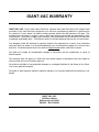
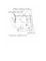
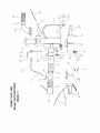
THE GIANT-VAC
‘SWING-AWAY-HITCH MOUNT’
TRUCK LOADER
MODELS TLH18201BVG-TLHX18201BVG-TLS18201BVG
OPERATOR’S MANUAL
Congratulations!
You have just purchased one of the finest pieces of outdoor power equipment on the market today. If
properly cared for, your Giant-Vac Hitch-Mount Truck Loader will provide years of dependable
service. Please read and follow this instruction manual carefully in order to get the most out of your
new equipment.
As you unpack your Giant-Vac truck loader, you will find the following:
1- Carton containing power unit with impeller
1- Carton containing hitch/swing arm assembly, complete intake and discharge assemblies,
hardware kit and manuals
Inspect parts for any damage that may have occurred in shipping. If any are found, save the packing
boxes and IMMEDIATELY notify the transport carrier who delivered your machine, as they are
responsible for the damage and are the only ones to make any adjustments.
Before leaving our plant, all parts are inspected to ensure proper fit, thus, you will have little difficulty
in assembling your Giant-Vac if you follow these steps.
CALIFORNIA PROPOSITION 65 WARNING
Gasoline and Diesel engine exhaust and some of its constituents are known to the State of
California to cause cancer, birth defects and other reproductive harm. As an owner of offroad gasoline or diesel engine equipment and/or as an employer, you also may have an
obligation under the California Occupational Safety and Health Act or under Proposition
65 to warn persons exposed to gas and diesel engine exhaust and/or other Proposition 65
chemicals in and around your workplace. See California Health and Safety Code section
25249.5, Title 22 of the California Code of Regulations at Section 1200 er seq., and Title 8
of the California Code of Regulations Section 5194.
1
SAFETY AND OPERATING INSTRUCTIONS
TRAINING:
1.
Regard your Giant-Vac as a piece of power equipment and teach this regard to all who will operate this
unit.
2.
Never allow children or young teenagers to operate the Giant-Vac.
3.
Be sure you know how to stop the engine at a MOMENT’S NOTICE.
4.
Instruct children to keep away from the area of operation at all times.
PREPARATION:
1.
Before starting operation, clear the entire work area of all debris that could catch on or be thrown by the
Truck Loader.
2.
Unless there is very good artificial light, use only during daylight.
3.
Fill gasoline driven machines outdoors. Avoid spilling gasoline and DO NOT fill the engine while it is
running or while you are smoking.
4.
Be certain the intake hose boom is properly adjusted according to the instructions found in an earlier
section of this manual.
OPERATION:
1.
Never insert any body part or other foreign object in any opening while the machine is running.
2.
CAUTION: When transporting the truck loader, do NOT exceed 30 M.P.H. High speed driving and
poor road conditions can cause damage to the truck loader and the tow vehicle. Make sure the
hose and boom are secured before towing your truck loader.
3.
Do not operate with guards or component parts removed from unit.
4.
Before making any adjustments or repairs, stop engine and remove spark plug wire.
5.
While in operation, keep all parts of body away from intake and discharge sections.
6.
When operating machine, keep people and pets a safe distance away.
7.
Before starting, be certain to check the engine’s OIL AND GASOLINE. (See engine manufacturer’s
Service Manual). NEVER check the engine while engine is running or while you are smoking. Check
only when engine is cold.
8.
NOTE: Before starting engine, be certain unit is completely assembled.
1 SAFETY AND OPERATING INSTRUCTIONS (cont.)
18 HP UNITS: Put acid in the battery and make sure the battery is charged. Attach both battery cables. Slide
throttle control to the uppermost position. When engine is cold, you may have to initially choke
engine. (The choke lever is located above throttle control.) Next, turn key past ‘run’ position to ‘start’. After the
engine starts, release key (it will automatically spring back to ‘run’ position), and move throttle lever down to
approximately halfway.
9.
After the machine is running, check the adjustment of the chain on the hose support. This is vitally
important for ease of operation. To make this check, speed up the engine. You should then be able to
push the nozzle to the ground and pull it back up by using three fingers of one hand. If you cannot
operate the nozzle accordingly, the chain should be readjusted. In operation, you will note the boom will
readily swing over an 8-foot path.
10.
We recommend the following for efficient use of the Truck Loader. If the leaves are dry, run the
machine at approximately half throttle. This will help reduce the amount of small particles of debris
escaping through the exhaust screen. When the leaves are wet or partially frozen, run the machine at
full throttle. If the pile of leaves is high, a short back and forth sweeping motion will effectively eat into
the pile of leaves. If the leaves are wet, it is best to move into the pile with a gulping motion. In this
way, you will pick up a quantity and then move the hose slightly away from the pile to allow the leaves to
rapidly flush through.
11.
Never use your Giant-Vac Truck Loader to pick up sand or stones. Debris like this is very abrasive and
can damage the impeller and blower housing.
12.
The Truck Loader is designed to be used in conjunction with a truck that has a receiver box installed.
Be sure the receiver box is of adequate construction to withstand the high velocity and force of the
incoming debris. NEVER run or operate your Truck Loader unless it is completely connected to a
receiver box and the intake hose is installed.
13.
NEVER allow a person to ride, sit or stand on the Truck Loader. NEVER allow a person to ride, sit or
stand on the towing vehicle other than in the driver’s cab of the towing vehicle.
14.
Make sure that the driver of the towing vehicle has the operator of the Truck Loader in full view at all
times. Also, when operating the Truck Loader, instruct the operator to stay to the side of the machine,
never in front or behind.
2
ASSEMBLY INSTRUCTIONS
1.
Insert Hitch/Swing arm assembly into pickup truck hitch receiver and secure with pin and hairpin cotter
(not supplied).
2.
Install power unit on hitch mount assembly with impeller to the rear and secure with four (4) 1/2” x 1-1/4”
hex head bolts (Parts List Ref. # 42), flat washers (#29), lock washers (#25) and nuts (#24).
3.
Install Intake flange (#4) to power unit with 5/16” x 3/4” bolts and lock washers (#5). Flip up Intake
flange safety cover (#8; this should already be installed onto the intake flange by the factory) and install
quick-attach hose adapter (#11) to intake flange. Important: Be sure to lock hose adapter into
intake flange by pushing adapter into flange as far as it will go, then twisting into locking slots.
Secure adapter by installing 5/16” fender washer (#12) and 5/16” plastic knob nut (#13) onto each
adapter stud. Install 5/16” locknut (#14) onto each stud, tightening snugly against knob nut to prevent
loosening and/or loss of knob nut, and subsequent disconnection of hose adapter.
4.
Attach intake hose (#16) to hose adapter using one hose clamp (#15). Assemble hose support band
(#17) around intake hose approximately 3½ feet from free end of hose using 5/16” hex head bolt (#18)
with two nuts (#19) locked together. Now attach intake nozzle (#20) to loose end of intake hose using
the remaining hose clamp.
5.
Install discharge stack (#27) on top of blower housing outlet and fasten with two (2) 1/2” x 4-1/2” hex
bolts (#28)*, four (4) flat washers (#29), lock washers (#25) and nuts (#24).
*At this point, install turnbuckle (#33) onto unit by first sliding 1/2” x 4-1/2” bolt with one flat washer down
through hole in the discharge stack mounting bracket located under boom support bracket. Slide eye
end of turnbuckle onto bolt, then slide bolt down through mounting bracket on power unit, securing with
second flat washer, lockwasher, and nut.
6.
Install discharge elbow (#30) on top of stack * using two 1/2” x 4-1/2” hex bolts (#28), four flat washers
(#29), two lock washers (#25) and nuts (#24) as described in previous step. Attach flexible metal
discharge hose (#32) to discharge elbow using squeeze ring (#31), taking care to tighten squeeze bolts
evenly and securely. Insert metal hose through debris box door. (Information concerning debris box
contained further along in this manual.) * BE SURE THAT ELBOW IS ATTACHED TO STACK AS TO
DIRECT DISCHARGE INTO THE BED OF THE TRANSPORT VEHICLE.
7.
Assemble upper and lower boom supports (#22, 23) using two (2) 1/2” x 1” bolts (#26), lock washers
(#25) and nuts (#24). Slide round portion of lower boom through hole in boom support bracket and over
pin on top of blower housing. Attach boom chain (#21) to hole in upper boom support using S-hook on
end of chain. Feed other end of boom chain through eye in top of hose support band and attach S-hook
to link in upper section of chain. Adjust to support nozzle approximately 12” above ground level.
3
UNIT OPERATION AND TRANSPORT
FOR TRANSPORT:
1.
Connect safety chain on swing arm to vehicle (there should be a hookup on the vehicle hitch for this) to
prevent unit from swinging to open position during transport.
2.
Extend turnbuckle on power unit (Step 5 of assembly instructions) by turning out either end as far as
possible. Fasten S-hook end of upper body support chain (#34) to a good, strong point on the vehicle
(installing a heavy duty eyebolt onto the debris box would be ideal). Fasten chain to hook end of
turnbuckle, taking up as much slack as possible to keep the chain taut. Tighten further by taking in
turnbuckle (This is done by rotating center portion of turnbuckle in appropriate direction) until chain is as
tight as possible.
3.
Remove boom chain and swivel boom to side of truck bed and secure with a rope or hardware. It is
recommended disconnecting intake hose assembly from power unit via hose adapter, and fastening
hose assembly to debris box with two or three transport mounting brackets (not included). Or place
intake hose over engine frame and secure with bungee cord or similar tie down to hold hose and nozzle
during transport.
4.
(Optional Long Swing Arm Only) Fasten hook end of Secondary safety turnbuckle (#45) to vehicle (See
notes on fastening to vehicle in Step 2). Hook one end of Secondary safety chain (#46) to eyebolt end
of turnbuckle. Feed other end of chain through eye on end of swing arm. Pull taut, and then fasten Shook to upper section of chain. Tighten securely by taking in turnbuckle.
WHEN TRANSPORTING THE TRUCK LOADER, DO NOT EXCEED 30 M.P.H. HIGH SPEED DRIVING AND
POOR ROAD CONDITIONS CAN CAUSE DAMAGE TO THE TRUCK LOADER AND THE PICK UP TRUCK.
DEBRIS BOXES: IMPORTANT: The Giant-Vac Hitch Mount Truck Loader is designed to be used in
conjunction with a truck that has a leaf receiver box installed. NEVER run or operate your Giant-Vac Truck
Loader unless it is completely connected to a receiver box and the discharge hose is installed. Following are a
few suggestions for constructing a leaf debris box. To begin with, it is extremely important to have an adequate
screen for allowing air to escape. We strongly recommend the entire top of the box be covered with screening.
Flattened ¼” expanded metal mesh or ¼” square wire makes an excellent screen. The debris box is generally
fabricated out of plywood and angle iron. A 3” angle iron frame is first fabricated. Then the sides are lined with
¾” thick exterior type plywood. A frame is made for the top and then covered with metal screening. A door
should be fabricated from angle iron and plywood with a hinge on top. Do NOT use any thinner plywood, as the
internal pressure is apt to blow the sides out. A hole slightly larger than the discharge hose diameter (approx 71/2 - 8”) should be cut in the rear door so that the leaf loader can discharge debris into the box. Make sure that
this is a tight fit. Also, a rubber gasket (not supplied) should be placed around this hole. This will also help keep
debris from the engine air intake of the truck loader.
NEVER INSERT ANY BODY PART OR OTHER FOREIGN OBJECT IN ANY OPENING WHILE THE
MACHINE IS RUNNING.
MOTOR INSTRUCTIONS: You have received a complete engine manual with your machine. Be sure to
especially note the instructions on OILING. ALL MACHINES ARE SHIPPED WITHOUT OIL OR GASOLINE
UNLESS OTHERWISE NOTED. If you have any difficulties with the engine, check the Yellow Pages of your
phone book for the engine dealer nearest you, rather than us, as the engines are under their own
manufacturer’s warranty.
4
MAINTENANCE AND STORAGE
MAINTENANCE AND STORAGE:
1.
Follow implicitly the engine manufacturer’s recommendations for maintenance and storage.
2.
Never adjust the Truck Loader or change attachments until the engine has been turned off and the
spark plug wire has been disconnected.
3.
If carburetor adjustment is necessary, stand to one side and keep feet and hands in the clear while
making adjustments.
4.
Keep engine free from accumulations of grass, leaves or excessive grease. An accumulation of these
combustible materials may result in a fire.
5.
Store gasoline in a safe and approved container in a cool dry place.
6.
Keep the Truck Loader and fuel container in locked storage to prevent children from playing and/or
tampering with them.
7.
Gasoline powered equipment or fuel containers should not be stored in a basement or any closed area
where heating or heat appliances or open pilot lights are present, unless the fuel is completely drained
from the power equipment and the fuel containers.
GIANT-VAC WARRANTY
GIANT-VAC, INC., here in after called Giant-Vac, warrants each new Giant-Vac to the original retail
purchaser of the new Giant-Vac equipment to be free from manufacturing defects in normal service
for a period of 1 year, unless it is used for rental purposes, which limits the warranty to 30 days. This
warranty does not apply to engines, tires or other parts that are purchased and warranted by their
manufacturer. Items such as bags, grass catchers, hose and blades are not warranted, as these are
considered expendable items. This warranty does not include equipment failures due to normal wear.
Any obligation under this warranty is expressly limited to the replacement or repair, at an authorized
servicing Giant-Vac dealer, or at a point designated by us, of such parts as appear to us to have been
defective. All defective parts have to be returned freight prepaid before credit will be issued.
We shall not be liable for transportation charges in connection with the replacement or repair of
defective parts.
This warranty does not apply to a Giant-Vac upon which repairs or alterations have been made by
others except with our prior written approval.
We shall not be liable for consequential damages or contingent liabilities for the fitness of any GiantVac for any particular purpose.
We make no other express, implied or statutory warranty, nor is anyone authorized to make any in our
behalf.
GIANT-VAC, INC.
535 Macon Street
McDonough, GA 30253
PHONE: 866-792-8223
REF.
NO.
PART
NO.
1
2
3
4
5
8
9
10
11
12
13
14
15
16
17
18
19
20
21
22
23
24
25
26
27
28
29
30
31
32
33
34
35
36
37
38
39
40
41
-43
44
45
46
10151
21609
31020
20209
31031
20203
31461
31406
20212
31578
31626
31436
34016
34007
40109
31141
31004
20163
31140
40122
40130
31022
31078
31093
24665
31021
31043
24666
34047
34089
31624
31627
27261
27262
27263
27264
31454
31630
31489
31462
23195
31625
31624
31140
DESCRIPTION
Motor Base & Housing
Impeller
7/16-20 x 2 Impeller bolt, Washers & Key Kit
Intake Flange 10"
5/16 x 3/4 Hex Bolt & Lock Washer
Intake Flange Safety Cover 10"
1/2 x 2-1/2 Hex Bolt
1/2 Lock Nut
Quick-Release Hose Adapter 10"
5/16 Fender Washer
5/16 Plastic Knob Nut
5/16 Lock Nut
10" Hose Clamp
10" x 10' Intake Hose
10" Support Band
5/16 x 3-1/2" Hex Bolt
5/16 Nut
Intake Nozzle 10" w/Adj Handle
Boom Chain
Upper Boom Support
Lower Boom Support
1/2 Nut
1/2 Lock Washer
1/2 x 1" Hex Bolt
Discharge Stack
1/2 x 4-1/2" Hex Bolt
1/2 Flat Washer
Discharge Elbow
7" Squeeze Ring
7" x 30" Metal Discharge Hose
3/8 x 7-1/2" Turnbuckle
Upper Body Support Chain
Standard Swing Arm - Vehicle Side
Standard Swing Arm - Unit Side
Long Swing Arm - Vehicle Side
Long Swing Arm - Unit Side
Swing Arm Bushing
Swing Arm Pivot Pin
5/8 Flat Washer
1-1/4" Single Split Collar
Swing Arm Locking Bracket
5/8-11 Handle
3/8 x 7-1/2" Turnbuckle
Boom Chain (Secondary Safety Chain Long Arm)
TLH18201
TLHX18201
TLS18201
1
1
1
1
8
1
1
1
1
2
2
2
2
1
1
1
2
1
1
1
1
10
11
2
1
4
11
1
1
1
1
1
1
1
--2
1
1
1
1
1
1
--
1
1
1
1
8
1
1
1
1
2
2
2
2
1
1
1
2
1
1
1
1
10
11
2
1
4
11
1
1
1
1
1
--1
1
2
1
1
1
1
1
1
1
1
1
1
1
8
1
1
1
1
2
2
2
2
1
1
1
2
1
1
1
1
10
11
2
1
4
11
1
1
1
1
1
-------------
ITEMS NOT SHOWN
70863
39058
31612
31562
31633
31634
39025
39186
31002
31003
31004
27265
27266
79174
79300
79301
79302
Housing Liner (w/hardware)
Battery
Battery Hold-down
#12 x 1/2" Sheet Metal Screw
Battery Cable - Positive
Battery Cable - Ground
18hp B&S Vanguard Engine
Muffler Guard
5/16-18 x 1-3/4" Hex bolt
5/16 Lock Washer
5/16-18 Hex Bolt
Standard Swing Arm Assembly - Complete
Long Swing Arm Assembly - Complete
Decal, GV Logo, 9in White on Black
Decal, Danger Safety
Decal, Warning Safety
Decal, Notice
1
1
1
1
1
1
1
1
1
1
1
1
-1
1
1
1
1
1
1
1
1
1
1
1
1
1
1
-1
1
1
1
1
1
1
1
1
1
1
1
1
1
1
1
--1
1
1
1