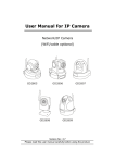
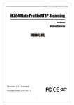
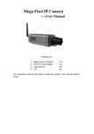
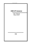
1
SNR-CI-H Series
Network IP Cameras User Manual
SNR-CI-H Series
Network IP Cameras User Manual
Statement
Thank you for using our IP camera products. This series of products are all-in-one IP cameras designed for network video
surveillance, including box IP camera, infrared box IP camera, dome IP camera, speed dome IP camera, etc. The products adopt
high performance and powerful single SOC chip media processor to integrate audio and video capture, compression and
transmission. Standard H.264 Main Profile coding algorithm ensures clearer and smoother video transmission effect. Built-in Web
Server allows users to easily perform real-time monitoring and remote control over front-end cameras via IE browser.
This series of IP cameras is suitable for small and medium-sized enterprises, families, and other environments that require
remote network video transmission and monitoring. It is easy to install and operate.
Before installation, please check to see whether you have the product and all accessories ready. If anything is missing,
please contact your supplier in time.
Package contents:
1 IP Camera
----1pc
2 Power Adapter (model depends on the camera model)
----1pc
3 User ’s
----1pc
Manual
4 Compact Disk
----1pc
5 Certificate of quality
----1pc
6 Warranty Card
----1pc
Optional Accessories:
1 WIFI Antenna
----1pc
Notes:
“IP Camera” mentioned in this manual refers to network camera, including box IP camera, dome IP camera, infrared box
IP camera, speed dome IP camera, etc.
Click - press the left mouse button once
Double-click - press the left mouse button twice
Note:
Contents in this manual may be different from the edition that you are using. Should any unsolved problem occur given
that the product is used according to this manual, please contact our technical support department or your product
suppliers.
The content of this manual may be updated at irregular intervals without prior notice.
II
SNR-CI-H Series
Network IP Cameras User Manual
Table of Contents
1 Product Overview
1.1 Product Application
1.2 Features
1.3 Technical Parameters
1.4 Application Environment
2 Appearance and Installation
2.1 Back panel connection diagram of box IP camera
2.2 Back panel connection diagram of dome IP camera
2.3 Infrared box IP camera connection diagram
2.4 Dome IP camera connection diagram
2.5. Hardware Installation
3 Downloading and Installation of Searching Device and ActiveX
3.1 Searching Device and Modifying Network Parameters
3.2 Check Connection
3.3 Install ActiveX and Login
4 FAQs
III
1
1
1
2
3
4
4
5
6
7
8
9
9
11
12
13
SNR-CI-H Series
Network IP Cameras User Manual
1 Product Overview
1.1 Product Application
IP camera can be used for surveillance in public places, such as in supermarkets, schools, factories, warehouses and so on.
Also because of its strong image-processing performance, it can be used in some advanced environments, such as banks and r
transportation systems that require higher image definition.
1.2 Features
Adopts high performance and powerful media processor, single SOC chip, built-in (ARM+DSP) and high speed video
protocol processor
High sensitivity CCD or progressive CMOS sensor
Supports infrared night vision function (depending on specific models)
Supports optical zooming and automatic focusing (depending on specific models)
Standard H.264 video compression algorithm to satisfy the transmission of high definition video in narrow bandwidth
network.
Supports local storage of SD card (depending on specific models), maximum capacity is 32GB;
Supports UPNP function, plug-play system brings convenience to users
Built-in Web Sever, users can visit the IP camera to realize remote surveillance and control via standard IE.
Supports IEEE802.11a/b/g/n wireless transmission protocol
Supports remote system upgrade
Supports dynamic domain name service, LAN and Internet (ADSL, Cable Modem)
Supports multiple network protocols: HTTP, TCP/IP, UDP, SMTP, DDNS, DNS, SNTP, BOOTP, DHCP, FTP, SNMP, RTP,
UPNP
Bi-directional audio talkback and broadcast;
Network self-adapting function: adjust stream and encoding frame rate automatically according to network bandwidth
Provides motion detection (area and sensitivity can be adjusted) and E-mail alarm functions
Provides RS485/RS232 serial port, various decoder protocols can be built in, supports transparent transmission protocol
Auto-recovery when incident occurs and auto-connection if the network interrupts
-1-
SNR-CI-H Series
Network IP Cameras User Manual
1.3 Technical Parameters
Image Sensor
CCD
Supports all models of SONY/SHARP interlaced CCD image sensor
CMOS
Progressive scanning image sensor
Video Compression
H.264 Main Profile, MJPEG
Dual streaming
Supports preferred stream and alternate stream
Video Definition
CCD
Maximum D1 (704x576 PAL,704x480 NTSC)
CMOS
Maximum VGA (640*480), progressive scanning
Video Parameters
lightness, contrast, saturation, chroma and image quality
Streaming Format
Pure Video Streaming or Audio&Video composite Streaming
Video Frame Rate
CCD
1-25frames/second (PAL), 1-30frames/second, adjustable
CMOS
1-25 fps, adjustable
Video compression bitrate
30Kbps~16Mbps
Auto Iris Lens Control
Supports DC-driven lens(depending on specific model)
Title Overlay
Supports channel name, date/time and stream information overlay, overlay location
adjustable by users
Audio Input
1 channel linear or passive MIC input, 2.2KΩ impedance
Audio Compression
G.726
Audio Output
1 channel linear output
Audio Talkback Input
Built-in MIC (depending on the specific model)
10Base-T/100Base-TX Ethernet Port
System Interface
1 RS485 interface
SD card interface (SD2.0 standard, maximum capacity 32 G)
Wireless network
Built-in WiFi module (supports IEEE802.11a/b/g/n ) (depending on specific models)
Built-in 3G module (CDMA2000/WCDMA/TD-SCDMA) (depending on specific models)
Wireless Encryption Method
WEP, WPA, WPA2
PoE function
Built-in PoE module (depending on the specific model)
RTSP protocol
Supportive
Mobile monitor
Supportive (optional)
Alarm Input
1 channel on/off input, supporting NO (normally open) or NC (normally close) mode.
Alarm Output
1 channel on/off output,120VAC 1A/24VDC 1A
E-mail Alarm
Supports alarming e-mail transmission, snapped pictures can be attached
Working temperature
-10 ℃ ~ +55 ℃
Working Humidity
10% ~ 85%
Storage Temperature
-20 ℃ ~ +70 ℃
-2-
SNR-CI-H Series
Network IP Cameras User Manual
1.4 Application Environment
Minimum configuration of hardware environment
CPU: Pentium 2.0.Ghz
System Memory: 256MB
Graphics Card: TNT2
Sound Card: necessary for audio surveillance and talkback
Hard Disk: minimum 40G capacity required for image recording.
Recommended configuration of hardware environment
CPU: Pentium 2.6GMhz
System Memory: 512MB
Graphics Card: Nvidia Geforce FX5200 or ATI RADEON 7000(9000) serials 128M Display Card Memory
Operation system
32-bit Simplified Chinese & English editions of Windows2000, WindowsXP, Windows2003, Windows Vista, 64-bit Simplified
Chinese & Englsih editions of Windows2003, WindowsXP, Windows Vista, etc.
Software Environment
IE 6.0 version or above
DirectX8.0 edition or above
TCP/IP
Other requirements:
The PC installed with this software requires a graphics card that supports the color change and zoom of image, now the graphics
card that has been tested are: Nvidia Tnt/Tnt2、Geforce Mx200/400/420/440 Fx5200/5600 series, ATI Radeon
7000/7200/7500/8500/9000/9200/9500/9600 series, MatroxG450/550 and INTEL845G/865G series. Please note that the graphics
card driver must be hardware scaling supportive.
-3-
SNR-CI-H Series
Network IP Cameras User Manual
2 Appearance and Installation
2.1 Back panel connection diagram of box IP camera
Picture 1 back view of box IP camera
Picture 2: back panel illustration of box IP camera
Back-end panel interface description:
DC12V: Power input, DC12V/1A
LAN: Ethernet port;
AUDIO OUT: Audio Output;
AUDIO IN: Audio Input;
SD CARD: SD card slot;
VIDEO OUT: Video Output;
ALARM: Alarm input and output, 1A and 1B connect to alarm output, IN connects to alarm input, G connects to signal
ground;
RS485: RS485 Control interface, left side connects to RS485 -, right side connects to RS485 +;
USB: USB interface;
RESET: Reset button, restore to factory settings, and please use this button with caution;
ANT: wireless antenna interface;
POWER: Power Indicator Light
DC AUTO IRIS: Auto Iris Lens interface, supports DC lens.
-4-
SNR-CI-H Series
Network IP Cameras User Manual
2.2 Back panel connection diagram of dome IP camera
Picture 1: back view of dome IP camera
Picture 2: back panel illustration of dome IP camera
Back-end panel interface description:
wifi: wireless antenna interface;
USB: USB interface;
DC12V: Power input, DC12V/1A
Vout: Video Output;
LAN: Ethernet port;
ALM OUT: alarm output, A and B connect to alarm output;
ALM IN: alarm input, IN connects to alarm input, GND connects to signal ground;
RS232: RS232 control interface, left side is for receiving data, right side is for transmitting data.
AIN: audio Input;
AOUT: audio output;
MIC: MIC input, INT built-in MIC, EXT external MIC;
SD CARD: SD card slot;
RESET: Reset button, restore to factory settings, and please use this button with caution;
RF: RF antenna port
-5-
SNR-CI-H Series
Network IP Cameras User Manual
2.3 Infrared box IP camera connection diagram
Picture 2 Infrared box IP camera (cable model)
Picture 6 Infrared box IP camera connection diagram
Connection cable ports description:
DC 12V: Power input, DC12V/3A
LAN: Ethernet port;
Audio in: Audio Input
Audio out: Audio Output
RESET: (Yellow) Reset button, restore to factory settings, please use this button with caution;
GND: (Grey, brown) signal ground, alarm input, RS485
ALARM IN: (Red) on/off alarm input
ALARM OUTA: (Orange) on/off alarm output A
ALARM OUTB: (Purple) on/off alarm output B
RS485 +: (Green) RS485 control interface +
RS485 -: (Blue) RS485 control interface -
-6-
SNR-CI-H Series
Network IP Cameras User Manual
2.4 Dome IP camera connection diagram
Picture 7 Speed dome IP camera
Picture 8 Low speed dome IP camera
Picture 9 Mini high speed dome IP camera
Picture 10 Mini high speed dome IP camera
connection cables
Connection cable ports description:
DC IN: Power input (input voltage depends on specific models)
LAN: Ethernet port;
Audio in: Audio Input
Audio out: Audio Output
RESET: (Yellow) Reset button, restore to factory settings, please use this button with caution;
GND: (Grey, brown) signal ground, alarm input, RS485
ALARM IN: (Red) on/off alarm input
ALARM OUTA: (Orange) on/off alarm output A
ALARM OUTB: (Purple) on/off alarm output B
RS485 +: (Green) RS485 control interface +
RS485 -: (Blue) RS485 control interface -
-7-
SNR-CI-H Series
Network IP Cameras User Manual
2.5. Hardware Installation
2.5.1 Connect IP camera via IP switch
See below picture for the connection mode:
Picture 11 IP camera is connected to network via switch
Step 1: Connect network cable to the LAN interface of IP camera;
Step 2: Connect power adapter to the power supply port of IP camera, and switch on the utility power.
Step 3: Connect the other end of the network cable to switch, router or hub;
Step 4: After the connection completes, enter the IP address of IP camera into IE for normal visit.
2.5.2 Connect IP camera directly via crossover cables
Connect IP camera to PC with crossover cable, see below picture:
Picture 12 IP camera is connected to PC via crossover cable
Connection Indicator Light (Orange) will be on in five seconds under normal condition, indicating the physical connection of
IP camera has been finished successfully.
-8-
SNR-CI-H Series
Network IP Cameras User Manual
3 Downloading and Installation of Searching Device and ActiveX
3.1 Searching Device and Modifying Network Parameters
Use SearchNVS software to search and modify network parameters. The SearchNVS running method is as follows:
Put the CD in the package of IP camera in to CD driver, find Search NVS from [tool software] directory and copy it to PC,
double click to run the software.
Put the CD in the package of IP camera into the CD driver, find “NVS Center” setup file from central management software
catalog, copy it to your PC, double click it to run installation. After the installation completes, find Search NVS software via below
path: “Start Menu” —> “All Programmes” —> NVS Center.
Note:
1 The default IP address for each IP camera is 192.168.55.160, subnet mask is
255.255.255.0.
2 The default administrator user name and password of each IP camera are both “admin”.
3 Run the SearchNVS software to search and modify network parameters. It adopts multicast protocol to perform searching. But the
firewall forbids multicast data packet. So please disable the firewall first to obtain information.
Detailed steps are as follows:
1 Click [Search] button to run SearchNVS software, see the following picture:
[Connect NVS Local IP]: local IP of PC displayed. If your PC is NIC or has multiple local IP address, please select an IP
address to connect DVS.
The main window indicates that your PC has found the IP camera in LAN. If there are several IP cameras in your LAN, you
can determine which camera is the one you purchased through “device name” in the main window. There is a unique device ID
number in your package, and the default device name is “NVS + device ID number”.
2 Set IP address for IP camera
The IP address of your PC and the IP camera must be in the same network segment to make visiting to the IP camera
possible. So you may need to reset the IP address for the IP camera before using it.
Check network settings of the PC
View PC configuration information: click “start”, choose “run”, then input “cmd”(Windows 2000/XP system). Click “confirm”,
then input “ipconfig” and press “Enter” button, you will get following information:
Set IP address for IP camera
Click [Set Parameters], modify IP address of the IP camera to be in the same segment as that of the PC, and avoid its conflict
with PC or other IP devices.
-9-
SNR-CI-H Series
Network IP Cameras User Manual
Modify related network parameters, click “OK”, the IP camera will save the parameters and restart.
-10-
SNR-CI-H Series
Network IP Cameras User Manual
3.2 Check Connection
Check to see whether the IP camera is running and is properly connected: “Start”→ “Run”→ “cmd” , open command window,
input: ping 192.168.1.100, click “Enter” button.
If the command can generate a reply, that means the IP camera works normally and is connected to network correctly. If not,
please confirm the IP address and gateway settings, and check the network cables.
-11-
SNR-CI-H Series
Network IP Cameras User Manual
3.3 Install ActiveX and Login
You need to install ActiveX Control when you visit IP camera for the first time through IE browser.
ActiveX installing method:
Download installation
Input the IP address of IP camera in Internet Explore to enter into login page,
Click [File] to download the ActiveX:
Download ActiveX
File download dialogue box pops up, click [Run] or [Save] to download ActiveX, after download it , double-click the downloaded file
“xdview.exe” to install it. After installation completes, a message “Register OCX success!” will appear(see picture 14):
图 14
Open Internet Explorer after installation completes, and input IP address of the IP camera (for example:192.168.55.160) to
enter into login page as follow:
Input User name (Default: admin)、Password (Default: admin),click “login” to enter into the main interface, see below picture:
Live
Preview
Parameter
settings
Image
display
area
PTZ
control
Note: Please refer to “IE browser user’s manual(HH9800 series IP camera.doc)” for parameter settings
-12-
SNR-CI-H Series
Network IP Cameras User Manual
4 FAQs
1 Forget Password
Solution: There is a [RESET] button on the back panel of the IP camera, press it to restore all default parameters (Factory
Setting), user name and password are both “admin”.
Note: Please don’t press RESET if you are not a professional operator. After reset, all parameters will restore factory settings
(except for the physical network address).
2 、 IP camera audio/video function fails after abnormalities or abnormal power cut occur during upgrade, core
edition is V4.0.0.0 (Backup file)
Solution: Connect the power cord and network cable of IP camera, press on RESET button and release it after 10 seconds,
system will run the back-up programme automatically. After enter into the back-up programme, upgrade system. After upgrade
completes, the IP camera will work normally. The back-up programme offers only upgrade and parameter setup functions, audio
and video functions are not available.
3 、 No video image displayed in IE browser
Possible reason: ActiveX not installed
Solution: ActiveX must be installed when visiting IP camera for the first time via Internet Explore.
How to install: Visit IP camera, click [Download Address], file download dialog will pop up, select [Run] or [Save] to download.
After download finishes, installation interface will pop up, click “install”,
the installation of ActiveX will start automatically,
“Register OCX success” dialog box will pop up to remind the completion of installation process.
4 、 Fail to visit IP camera via IE after upgrade
Solution: Delete the caching of Browser.
Steps: Open IE—click “Tools”—select “Internet Options”—click “delete files” button in “Internet temporary files”, select “delete
all offline contents”, then click “OK” and re-log in IP camera.
5 、 The images do not flow
Possible reason 1: The frame rate of IP camera is too low.
Solution: Increase the video frame rate
Possible reason 2: Too many users are viewing the images.
Solution: Block some clients or reduce the video frame rate.
Possible reason 3: The bandwidth is low.
Solution: Reduce video frame rate or video compression bitrate.
6 、 Fail to visit IP camera via IE browser
Possible Reason 1: Network is disconnected.
Solution: Connect your PC to network, checking whether it works properly or not. Check whether there is cable failure or
network failure caused by PC virus, until PCs can be connected with the command of Ping.
Possible reason 2: IP Address has been occupied by other devices
Solution: Stop the connection between IP camera and Network, hook up IP camera to PC separately, reset IP address
according to the proper operations recommended.
Possible reason 3: IP addresses are in different subnets.
Solution: Check IP address, subnet masking address of the DVS and the settings of Gateway.
Possible reason 4: Physical address of network conflict with IP camera
Solution: modify the physical address of IP camera.
Possible Reason 5: Web port has been modified
Solution: Contact Network Administrator to obtain related information.
Possible Reason 6: Unknown
Solution: Press RESET to restore default settings then connect it again, the default IP address is 192.168.55.160, subnet
-13-
SNR-CI-H Series
Network IP Cameras User Manual
mask is 255.255.255.0
7 、 The color of images is abnormal (green or other colors)
Solution: Sometimes IP camera images cannot display properly for the difference between Graphics Cards, the images
appears to be green or other colors, then you should run the programme Config.exe (or run C:\windows\system32\Config.exe)to
set the following parameters of display buffer: auto-detection, used display card memory or system memory, then reopen IE and
connect IP camera.
8 、 There is no sound while monitoring
Possible Reason: No audio input connection
Solution: Check audio connection of the host
Possible Reason 2: the audio option of IP camera is off
Solution: Check audio parameter settings to see if you have opened the audio.
9 、 Search NVS software cannot find device
Possible reason: Search NVS software adopts multicast protocol to perform searching. But the firewall forbids multicast data
packet.
Solution: disable the firewall.
10、
10 、 Image processing doesn’t work properly
Possible Reason 1: system issue, DirectX function is disabled, which will cause slow display of images and abnormal color.
Possible Reason 2: hardware issue, graphics card doesn’t support image acceleration and hardware zooming functions.(For hardware
issue, the only solution is to replace graphics card)
Solution: install DirectX image drive, then StartRuninput “DXDIAG” as follows:
Note:
Enable DirectDraw speedup, Direct3D speedup, AGP veins speedup in DirectX function. If they can not be enabled, that means DirectX
installation fails or hardware not supportive.
-14-