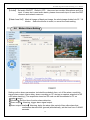
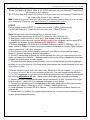
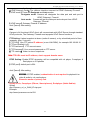
1
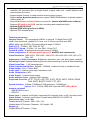
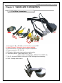
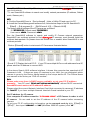
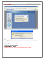
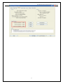
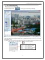
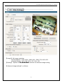
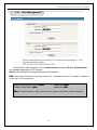
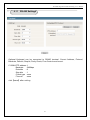
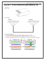
H.264MP-MegaPixels RTSP Streaming User’s Manual
H.264 Main Profile RTSP Steaming
Stand Alone
MegaPixels IP Camera
MANUAL
Firmware 2.2.1.3 Version
Revision Date : 2009.09.01
1
H.264MP-MegaPixels RTSP Streaming User’s Manual
WARNING: If the actions indicated in a “WARNING” are not complied with, injury
or major equipment damage could result. A warning statement typically
describes the hazard, its possible effect, and the measures that must be taken
to reduce the hazard.
CAUTION: If the action specified in the “CAUTION” is not complied with, damage
to your equipment could result.
NOTE: A “NOTE” provides supplementary information, emphasizes a point or procedure, or
gives a tip for easier operation.
CAUTION:
Any changes or modifications not expressly approved by the party responsible for
compliance could void the user’s authority to operate the equipment.
NOTE: This equipment has been tested and found to comply with the limits for a class digital device, pursuant
to part 15 of the FCC Rules. These limits are designed to provide reasonable protection against harmful
interference when the equipment is operated in a commercial environment. This equipment generates, uses,
and can radiate radio frequency energy and, if not installed and used in accordance with the instruction manual,
may cause harmful interference to radio communications. Operation of this equipment in a residential area is
likely to cause harmful interference in which case the user will be required to correct the interference at his own
expense.
Disposal of Old Electrical & Electronic Equipment
(Applicable in the European Union and other European countries with separate
collection systems)
This symbol on the product or on its packaging indicates that this product shall not be treated as
household waste. Instead it shall be handed over to the applicable collection point for the recycling of
electrical and electronic equipment. By ensuring this product is disposed of correctly, you will help prevent
potential negative consequences for the environment and human health, which could otherwise be caused
by inappropriate waste handling of this product. The recycling of materials will help to conserve natural
resources. For more detailed information about recycling of this product, please contact your local city
office, your household waste disposal service or the shop where you purchased the product.
2
H.264MP-MegaPixels RTSP Streaming User’s Manual
All the safety and operating instructions must be read before the unit is operated.
• Make sure not to connect the power before you install the camera.
• There is great chance of damaging your camera if the camera is opened by an unqualified
service engineer or installer.
• Avoid using the camera under direct sunlight (tropical area, Middle East), or near to any
source of heat.
Shielding is recommended.
• Don’t merge the camera under water; always put silicon gel on antenna connector after
installation to avoid corrosion and reducing the wireless link capability.
• Avoid exposing the camera to violent movement or vibration.
• Always use the camera in a well ventilated location to prevent overheating.
• Connect proper “Relay” between load and camera, to protect camera, don’t connect load
greater than 0.5A.
• Please use power adapter equipped with the camera, foreign power adapter with wrong
voltage may permanent damage your camera.
• Wireless link distance is depend on both camera (Wi-Fi client) and Access Point,
unbalanced transmit power won’t help extend the wireless link range.
• Clean the glass window frequently to ensure good clear view, remove the snow and ice
accumulated outside and inside of class window shield, keep camera inside dry by blow
dryer.
• Must use PSE come with POE camera
3
H.264MP-MegaPixels RTSP Streaming User’s Manual
Table of Contents
Chapter 1 Features.................................................................................................................................................................................5
Chapter 2 Packing Detail ...................................................................................................................................................................8
Chapter 3 Cable and Connectors................................................................................................................................................9
3.1 FRONT VIEW .................................................................................................................................... 9
3.2 REAR VIEW .................................................................................................................................... 11
Chapter 4 System Requirement .................................................................................................................................................14
4.1 The lowest hardware configuration.................................................................................................. 14
4.2 The recommended hardware configuration ..................................................................................... 14
Chapter 5 INSTALLATION..............................................................................................................................................................15
5.1 CONNECT to PC or LAN .............................................................................................................. 15
5.2 CONNECT to WAN ....................................................................................................................... 20
5.3 Install ActiveX and Login ............................................................................................................... 21
Chapter 6 Software Configurations ..........................................................................................................................................27
6.1 Menu Tree..................................................................................................................................... 27
6.2 Live View Page ............................................................................................................................. 28
6.3 Video Playback ............................................................................................................................. 32
6.4 System Settings ............................................................................................................................ 34
6.5 Video Settings............................................................................................................................... 36
6.6 Motion Alarm Setting..................................................................................................................... 38
6.7 Sensor Alarm Settings .................................................................................................................. 39
6.8 Network Setting............................................................................................................................. 41
6.9 Advanced Settings ........................................................................................................................ 44
6.10 User Management ...................................................................................................................... 46
6.11 RS-485 Settings .......................................................................................................................... 47
6.12 Storage Settings.......................................................................................................................... 48
6.13 Local Settings ............................................................................................................................. 50
Appendix 1
Network Port for IP Camera..............................................................................................................................51
Appendix 2
Network Factory Defaults....................................................................................................................................51
Appendix 3
Cross Ethernet Cable Making Tip................................................................................................................52
4
H.264MP-MegaPixels RTSP Streaming User’s Manual
Chapter 1
Features
H.264 Main Profile Encoding, Duplex Audio
Optional Wi-Fi, POE & Hi Power white LEDs
Clairvoyant mega-pixels IP Cameras offer cost-effective, indoor/ outdoor (Wi-Fi) IP
surveillance solution for remote monitoring and stand alone alarming over a local area
network or the Internet. Optional POE makes the wiring easier, only standard UTP Cat. 6
Ethernet cable required carrying both data and DC 48V power, no extra electric cable
required, Clairvoyant IP Cameras/ Video Servers are ideal for use in small or mid-sized
businesses and homes, it is also easy to set up and use.
Clairvoyant mega-pixels IP Cameras are embedded IP based smart devices designed for
(2.4GHz wireless) network video/audio surveillance applications. Optimized H.264 video
compression algorithm assures clearer and more fluent image transmission. Clairvoyant
mega-pixels IP Cameras adopt two mega-pixels CMOS sensor, the latest technology and
high integration single chip SOC with powerful Linux RTOS (Real-time Operating System) to
realize high performance and low cost digital multimedia processing. Built-in Web Server
allows users to conveniently carry out remote control via Internet Explorer. Furthermore,
central management software can be used for integrated surveillance and management of
multiple Clairvoyant mega-pixels IP Cameras/ Video Servers, very easy to build large
surveillance system.
Performance:
- PAN & TILT mechanism (C1228H)
- SOC single chip solution, equipped with two processors, ARM9 and DSP
- Support high sensitivity CMOS sensor
- H.264 main profile @ Level 3, realize transmission of High Definition video over low
network bandwidth easily.
- Support dual compression and dual video streams, more adaptive to different
network environment, display different resolution video on different client devices
(PC & phone)
- Up to 30 frames per second in all resolutions ranging up to 1280 x 960; 15fps@1600x1200
- Up to 10 viewers can directly access the camera simultaneously
- Stand alone alarming & motion detection; able to set 396 detective zones (22 x 18) each
with 100 levels sensitivity, send snapshots by scheduling or at alarm/ motion detected
through emails or upload pictures to FTP server.
- Built-in Web server enables the use of a standard Web browser for viewing and
management
- Support remote software upgrade safely function
- Support dynamic IP address (DDNS), LAN, Internet (ADSL PPPoE & DHCP)
- Network protocols: HTTP, TCP/IP, UDP, RTP, RTCP, RTSP, SMTP, PPPoE, DDNS, DNS,
SMTP, BOOTP, DHCP, FTP, NTP
- Support Bi-directional real time transmission of audio talk-back & broadcast.
- Network self-adapting technology to adjust video frame rate automatically according to the
network bandwidth.
- Auto-recovery function if exception occurs and auto-connection if the network fails
- Provide SDK and client demo source code.
5
H.264MP-MegaPixels RTSP Streaming User’s Manual
- Management software that can manage up to 1728 cameras in 48 groups, display
maximum 36 cameras video on single screen, support video lost、motion detection and
sensors alarm functions
- Support masks function to mask sensitive area to protect privacy.
- Support active & passive mode access, support GSM/ CDMA network or private network
without public IP.
- Support Multicast, unlimited clients connection. (match with NVSCenter software)
- Supports SD card up to 32GB, can store recording and snapshots locally.
- Optional POE-PD & PSE
- Optional IEEE 802.11g/b client (2.4GHz)
- Optional IP66 Weather proof
Technical parameters:
Imagine Sensor: Two mega-pixels CMOS, or optional 1.3 Mega-Pixels CCD
Lens: 6mm fixed focal, optional 3.6/ 8 mm, or 4.5~10mm vary-focal auto IRIS
LEDs: White light 36 LEDs, 30 meters effective range (C1222H)
PAN & TILT : C1228H : 355º PAN, 90º TILT
PAN & TILT Speed: C1228H : 12º /sec PAN, 12º/sec TILT
Presets & cruise: 32 presets with two point swing (C1228H)
Video compression: H.264 main profile @Level 3; M-JPEG dual compression
Video Resolution: 1600 x1200, 1280 x 960, 1280 x 720, 800 x 600, 640 x 352, 320 x 176,
160 x 120
Adjustment of Video Parameters: Brightness, saturation, accu, red, blue, gama, contrast
Streaming Format: Optional streaming format (video streaming or audio & video streaming)
Video Frame Rate: 1 - 30 frames/second
Video Compression Bit Rate: 16Kbit/S~16Mbit/S, constant bit rate or variable bit rate
Video Output: 1Vp-p, 75ohm, BNC
Audio Input: 1 channel linear input, Impedance:1kΩ
Audio Compression: MP3
Audio Output: 1 channel linear output
Audio talk-back input: 1 channel, MIC interface
Supported Protocols: HTTP, TCP/IP, UDP, RTP, RTCP, RTSP, SMTP, PPPoE, DDNS,
DNS, SMTP, BOOTP, DHCP, FTP, NTP
System Interface: 10 Base-T/100Base-TX Ethernet port; 1 RS485 port
Optional Wi-Fi: 2.4GHz, IEEE 802.11g/b with WEP, WPA, WPA2
Antenna (optional)
- 5dBi @2.4GHz, omni
- IPEX1.13
Alarm Input: 1 channel on/off input, supporting NO (normally open) or NC (normally close)
Alarm Output: 1 channel on/off output, Contact rating 220VAC 1A/ 24VDC 1A
Dimensions (mm, L x H x W):
Outdoor bullet IP Camera : 290 x 125 x 110;
Outdoor dome IP Camera : Diameter: 130, Height: 105
Weight (g):
Outdoor bullet IP Camera : 1.5kgs;
6
H.264MP-MegaPixels RTSP Streaming User’s Manual
Outdoor dome IP Camera : 2.5kgs
Input Power Supply: Optional POE-PSE
Maximum Power: Less than 8W, optional DC 48V POE-PD
Operating Temperature: -10 ~ +55 ℃
Storage Temperature: -20 ~ +70 ℃
Weather Proof: IP64 (Outdoor bullet IP Camera)
System Requirements:
Operation System:
Microsoft Windows XP, VISTA, Windows 7
Browser:
Microsoft Internet Explorer 6.x or above
7
H.264MP-MegaPixels RTSP Streaming User’s Manual
Chapter 2
Packing Detail
1. IP Camera
2. Installation Software utilities CD
3. AC Adaptor & Power Cord
1. IP Camera (optional Wi-Fi or POE)
2. Installation Software utilities & Central Management Software CD
3. AC Adaptor (DC12V/ 2A) & Power Cord
8
H.264MP-MegaPixels RTSP Streaming User’s Manual
Chapter 3
Cable and Connectors
3.1 Tail Wire Connectors
Video
1. Terminal (A+/ B-) : RS-485 A+/ B-; D+/ D- to control PTZ
2. Reset Terminal : Restore to factory default settings
3. RCA connectors : Female audio outputs to Speakers
4. Power connector : DC12V/ 2A
5. RCA plug : Male audio input port to sound monitor.
6. Terminals (Alarm) : Alarm input (NC or NO) /
Alarm output ( on/off output, 220VAC 1A/ 24VDC 1A)
7. RJ-45 : Network Ethernet connector, LEDs flashing when accessing
8. BNC : Analog video output
9
H.264MP-MegaPixels RTSP Streaming User’s Manual
Installing
10
H.264MP-MegaPixels RTSP Streaming User’s Manual
3.2 Optionals
Port Name
Description
1 RSMA Connector
○
2 Tail Cable
○
Detachable 5 dBi omni antenna
Optional high gain directional antenna
3 feet wire
Connect BNC output to monitors
RS-485 port can be used to connect the external PAN/ TILT Seat
No
1
2
DESCRIPTION
485A(TX+)
485B(TX-)
RS485:Transmit data
RS485: Receive data
Connect Pan/ Tilt Seat D+ , D- : Connect PT control line ( 485A , 485B terminal )
11
H.264MP-MegaPixels RTSP Streaming User’s Manual
Alarm input:
To connect the Active Infrared Sensor to IP CAMERAR camera ALARM IN, will trigger alarm
when light beams interrupted.
12
H.264MP-MegaPixels RTSP Streaming User’s Manual
Alarm output:
WARNING: If connect higher power loading (> 1A) directly to camera alarm out
will cause damage the camera.
Higher current (>0.5A) will accelerate aging of the relay on camera PCB,
external relay box is always recommended to protect the camera.
13
H.264MP-MegaPixels RTSP Streaming User’s Manual
Chapter 4
System Requirement
4.1 The lowest hardware configuration
.◆CPU: Intel Pentium 2.0GHz (Don’t support AMD CPU)
◆Memory:1,024MB
◆Graphics Card: TNT2
◆Sound Card: Speaker, Mic
◆Hard Disk: Recording Image,no less than 40G
4.2 The recommended hardware configuration
.
◆CPU: Intel Core2 DUAL 2.0GMhz or above
◆Memory: 2,048MB
◆Graphics Card: Nvidia Geforce FX9400 or ATI RADEON 9000 series 256MB video
memory, graphic card supports hardware Scaling
The PC graphics card must support hardware zoom in & out.
Tested Graphics Cards are as follow:
•
•
•
•
•
Nvidia TNT/ TNT2,
Geforce GTX295/285; Fx 8800/ 9600/ 9800 and its series;
ATI Radeon 7000/7200/7500/8500/9550/9600/9700/9800 and X & HD series,
Matrox G450/ 550;
INTEL 865G/ 875G and its series.
Operation System
◆Chinese; English: Windows2000/ Windows XP/ Windows Vista/ Windows 7.
Software
◆IE 6.0 or above
◆DirectX 8.0 or above
◆TCP/IP protocol
14
H.264MP-MegaPixels RTSP Streaming User’s Manual
Chapter 5
INSTALLATION
5.1 CONNECT to PC or LAN
CAUTION:
Please use the DC power adapter that is provided with the camera.
Connecting camera to other power source will cause permanent damage
to the camera.
NOTE:
Please use straight Ethernet cable (CAT. 5e) to connect camera to your home/ office
network switch/ hub or a broadband router.
For Wi-Fi models, you will still need to connect camera to your PC by Ethernet cable at
first time installation, correct SSID, WEP/ WPA password & IP address must be set
before you can connect the camera wirelessly (See more in section 6.8 Network
Settings).
You will see two IP address by camera search software utility, if you didn’t remove the
Ethernet cable before the camera wireless connection.
15
H.264MP-MegaPixels RTSP Streaming User’s Manual
Click “Search Camera” on Utility CD auto-play menu*, will find all the Clairvoyant IP cameras in
your local network.
* To use SearchNVS software to search and modify network parameters (IP address, Subnet
mask, Gateway etc.).
NOTE:
A: Find the SearchNVS.exe in 【tool software】 folder of Utility CD and copy it to PC.
B: Install the Central Management software first, follow below steps to find the SearchNVS:
【Start】---【all programs】--- 【NVSCenter6.16】---【Search NVS】.
The factory default settings of the IP Camera are as follows
IP: 192.168.55.160; Subnet mask: 255.255.255.0
User name: admin; Password: admin
Run the SearchNVS software to search and modify IP Camera network parameters.
SearchNVS use multicast protocol to find Clairvoyant IP cameras, most firewalls forbid the
multicast data packets. So please close the firewall first or enable/ allow SearchNVS to use
multicast protocol.
Click on【Search】button to start search IP Cameras as illustrated below:
【Local IP 】Display the local PC IP. If your PC has multiple NICs or multi-addressed local IP,
please select an IP address to connect NVS.
In the above Search NVS software interface, it shows this computer has searched all IP
Cameras in LAN. If there are many IP cameras in your LAN, you can distinguish which
camera is yours by the Device Name based on the unique device ID. The Device Name
was named in the factory as “DVS+ID number”.
Note:
Please make sure there is DHCP server available, or set your PC IP address
manually. Your PC won’t “Obtain an IP address automatically” without DHCP connected.
SearchNVS won’t work on a PC without IP address.
Please select the correct Network Interface Card (that connected to cameras) IP address
for “Local IP” if you have multiple Network Interface Cards installed in your PC.
Set IP address for IP camera.
Your computer IP address must be “in the same subnet” of IP Camera in order to visit
IP camera. So we need to set the IP address of the IP camera before accessing
camera.
To get your PC IP configuration information: go to command mode by click 【Start】
【Run】”, then input “command” or “cmd”(Windows 2000/XP system).click “ok”:
16
H.264MP-MegaPixels RTSP Streaming User’s Manual
Type “ipconfig” at command prompt”, press “Enter” button, you will get your PC
Network Interface Card IP address/ Subnet mask/ Gateway information.
17
H.264MP-MegaPixels RTSP Streaming User’s Manual
Please remember the IP Address,Subnet Mask, Default Gateway,then setup the IP Camera
IP address according to your PC IP address to ensure computer & IP Camera IP
addresses are “in the same subnet” .
For example : Set IP Camera IP addresses to 192.168.1.100. Default Gateway & Subnet
Mask same as PC.
Click 【Set】to set “Network Parameter” as illustrated below:
Modify relative Network Parameters; click “OK”, then the IP camera will reboot.
Test the IP camera connection: go to command mode by click 【Start】---【Run】”, then
input “command” or “cmd” (Windows 2000/XP system).click “ok”,
Type “ping 192.168.1.100” at command prompt, press “Enter” button, you will get following
information:
The message shown on above indicates the IP Camera is functioning normally and connects to
18
H.264MP-MegaPixels RTSP Streaming User’s Manual
same subnet (LAN) correctly. If the screen displays other information, please confirm the IP
address settings and check the network cables again.
Warning:
Please consult your office network administrator to get a free IP for your
IP Camera, duplicated IP address will cause undesired problems.
CAUTION:
Please always write down the password and keep password in safe place.
Please kindly notice, if you forget password you set, you will have to
return the camera to manufacturer for recovery, there is no way to reset
password of your camera.
19
H.264MP-MegaPixels RTSP Streaming User’s Manual
5.2 CONNECT to WAN
Connect IP Camera to your broadband
router or NAT gateway.
Do the following setup:
1. Setup Virtual Server/ forward port on
your router to camera,
2. or set your Camera IP to router DMZ
3. Obtain DDNS service from mvDDNS if
you don’t have fixed public IP,
4. Setup DDNS account information to
your camera
5. Access camera URL through Internet.
Example:
http://your_camera.myddns.net:port
Please reference more details of Router
& mvDDNS setup on Reference User’s
Manual.
Note:
Clairvoyant IP cameras/ Video servers support PPPoE auto-dial-up, that you can connect
your camera directly to an ADSL modem, please remember to setup DDNS and email
parameters before you enable PPPoE function.
It's impossible to access “LAN IP” from Internet; IP started with 192.168.xxx.xxx is LAN IP.
LAN IP sometime called illegal IP, only legal “Public IP” can be accessed through Internet.
It’s not possible to access your LAN IP through Internet or you will be in big security threat,
Hackers can access your bank account information and secrets stored in your LAN PC
You will need to connect IP camera Internet before you can access from remote through
Internet, there shall be a “Gateway” connect your office network (LAN) to Internet (WAN),
usually it is a broadband router, you will need to change settings of your broadband router to
enable the accesses from Internet to your camera.
Connect IP camera Internet:
1. Port Forwarding: forward port 80 & 5000 (default web & data port) (See your router
manual)
2. Set DNS & Gateway settings of your camera
3. Register a ne w DDNS account for DDNS Service, Set DDNS settings of your camera.
20
H.264MP-MegaPixels RTSP Streaming User’s Manual
Note:
a. Broadband router is firewall in nature will block all accesses from Internet, you will need to
set virtual server (port forwarding) on your router, normally we will always suggest to use port
80 or port > 1024 for web port to avoid conflicts, port <1024 are frequently used by other
applications.
b. Check if the DNS & Gateway settings are correct, it is impossible to get out of your LAN if
wrong. (Gateway is the door, DNS is like "map", people won't go out home without knowing
where the door is or don't have map to find the way)
c. Always test the DDNS service from remote IP (that is outside of your LAN), some router will
block WAN port access from inside LAN.
5.3 Install ActiveX and Login
1. Install “OCX setup”, ActiveX controls (plug-in) required by IE browser is installed
simultaneously (click on the “Install 1st” tab on product CD pop-up Manu).
2. Download ActiveX controls (plug-in) required, set the safety property of IE in the PC only at
the first time accessing new IP Camera
Note:
Before Install “OCX setup” must close all IE browser windows.
Before accessing Clairvoyant IP Cameras/ Video servers through IE browser, please follow
below steps to “Add camera IP address or URL to your IE trusted sites list”.
In order to download & install ActiveX controls, you will need to add your camera IP/ url
address to your IE browser “Trusted sites”
IE browser “Tool” “Internet Options” “Security“
21
H.264MP-MegaPixels RTSP Streaming User’s Manual
Remember to un-check the “Require Server verification (https:) for all sites in this zone”
Type in http://CameraIP_address or URL to “Add this website to the zone:” field, click on “Add”
button.
22
H.264MP-MegaPixels RTSP Streaming User’s Manual
You can add you LAN subnet to your trusted sites by adding http://192.168.0.* if your LAN
subnet is 192.168.0.xxx.
Choose Custom level and enable all ActiveX features of Trusted sites zone
IE browser “Tool” “Internet Options” “Security“ “Custom Level”
”ActiveX control and Plug-ins” three settings should set to “Enable”,
Remember to set the Security level of “trusted sites” to Low, Click “Apply” or “OK” to save
Enable download and run un-signed ActiveX plug-ins.
Enable:Download unsigned ActiveX controls
Enable:Initialize and script ActiveX controls not marked as safe
Enable:Run ActiveX controls and plug-ins
23
H.264MP-MegaPixels RTSP Streaming User’s Manual
After installed CAMERA ActiveX controls, enable “Run ActiveX controls and plu-ins”, you
can view camera video as followed:
Type IP address of the IP camera in Internet Explore address field; Click “Enter” to
bring up the camera Login page as illustrated below:
24
H.264MP-MegaPixels RTSP Streaming User’s Manual
Download
ActiveX
Click【File】to download the ActiveX:
A new dialogue box will pop-up, click 【Run】to start Installing ActiveX:
Close current Internet Explorer Window, close all IE Windows.
after installed the ActiveX will show “Install OK”.
25
click “Install” button,
H.264MP-MegaPixels RTSP Streaming User’s Manual
Again, type IP address of the IP camera in Internet Explore address field; Click “Enter”
to bring up the camera Login page as illustrated below:
admin
Input User name (Default: admin)、Password (Default: admin),click “Submit” to bring up
camera video page:
Live View
System
Settings
Video
Settings
…..
Etc……..
Pan/ Tilt
control:
To control
Motion
Left,
Right, Up,
Down,
26
H.264MP-MegaPixels RTSP Streaming User’s Manual
Chapter 6
Software Configurations
6.1 Menu Tree
Snap
Record
Live view
Replay
Call
System/ NTP/ Storage Settings
Video/ Audio Settings
M
A
I
N
P
A
G
E
Alarm Set
Speaker
Motion
Alarm
Sensor
Log
Network Fault
Basic Set
Network Set
Zoom in
Full Screen
Advanced
Images Set
User management
Lens Control
Terminal
Storage Set
Device set
Record Set
Snap Set
Local Set
27
P/T Control
H.264MP-MegaPixels RTSP Streaming User’s Manual
6.2 Live View Page
In the Live view webpage, administrator can do operations :
Taking Snapshots, Recording, Playback, Talk-Back, Speaker, Alarm on/ off and Image
Parameters Settings.
【Snap】 click “Snap”, take the current image snapshot, which can be stored in your
computer hard drive in JPG format.
【Record】Manual video recording, the current video can be stored in your computer
in .MP6 format. The working status as:
【Replay】click “Replay”, it will bring up a new Playback window, user can playback the
recorded video or pictures captured.
【Call】Mic. on/ off,If user connects Microphone and Speaker with IP camera, it can
turn on the two way Audio function. The working status as:
【Speaker】Speaker on/ off,The working status as :
【Alarm】While there is an alarm, click on【Alarm】to stop the alarm manually .
【Log】Evens log
【Zoom in】Click on “Zoom in” change to red color, Select area to zoom in (live view)
28
H.264MP-MegaPixels RTSP Streaming User’s Manual
【Full Screen】Enlarge to full screen
【Pan control】up, down, left, right, Automatic, speed adjusting
【Image Parameters】
CCD IP Camera: brightness, contrast, chroma, saturation
adjustment as follows:
【Lens Control】It can be adjusted Zoom, Focus, Aperture, Light, Clip, Preset, and Pan
operation.
【P/T Control】Pan / Tilt operation, PAN speed adjustable
29
H.264MP-MegaPixels RTSP Streaming User’s Manual
Error Message
Note:
If you see above screen, which indicate your hardware is not powerful enough, please
choose PC with more advanced processor.
Minimum system requirement are:
CPU: PIII 2.0GHz or above; AMD processors are not supported
Display card : DirectX 9c compliant.
Start Run input DXDIAG
DirectDraw、Direct3D、AGP Texture Acceleration must be enabled
30
H.264MP-MegaPixels RTSP Streaming User’s Manual
31
H.264MP-MegaPixels RTSP Streaming User’s Manual
6.3 Video Playback
Click【Replay】button:
, to bring up the following webpage
User can search the recorded image files or snapshot pictures in local PC or SD card
according to date.
【Date】User can check the recorded video files or snapshot pictures according to the
selected date, click the button :
calendar appears:
Click
Click
Click
Click
“《 ”icon
“ 》”icon
“〈 ”icon
“ 〉”icon
32
to
to
to
to
previous year
next year
previous month
next month
H.264MP-MegaPixels RTSP Streaming User’s Manual
【PC】check the recorded video files or snapshot pictures in local PC according to the
selected date.
【SD Card】check the recorded video files or snapshot pictures in SD Card according to the
selected date.
【File List】Shows the selected recorded video files or snapshot pictures in the File List.
Check the current recorded video files or snapshot pictures in the list as follows:
There are two Lists: Record & Pic:
Record List means the recorded video in PC on Dec 6, 2007
Pic List means the snapshot pictures in PC on Dec 6, 2007
The left of the Record / Pic List is the Hour (from 0 to 23)
The right of the Record / Pic List is the Minute (from 0 to 59)
The yellow icon means the video recorded / pictures taken in the
selected time.
The blue icon means the video recorded / pictures taken on
other time.
This blue icon means the picture taken at 9:26 on Dec 6, 2007
Yellow icon means the video recorded at 10:38 on Dec 6, 2007
These files were named by the recording time. For example: the
file 10_38_40.mp6 means this video is recorded at 10:38:40'.
【
】Choose the recorded video or snapshot picture in play list, then click “play”
button as :
Playback control as follows:
Time table
The buttons from left to right:File, Play, Pause, Stop, Backward, Fast, Single
frame, Audio, Recycle, Snapshot.
【
】Searching the recorded video file or snapshot pictures which downloaded
from SD card in Play list, click the “
” button to download it to local PC.
【
】following window pop up after click the “
33
”:
H.264MP-MegaPixels RTSP Streaming User’s Manual
Click【Pause】to pause download manually,click【Start】to continue downloading
the remaining files,click【Delete】to del the file,click【Close】to close the download
information window.
6.4 System Settings
System Clock: click: “Time Sync”, The camera time will be synchronized with your computer.
【NTP Parameter】: Please input the correct NTP server address and select the correct time
zone. After save it, switch to【Live View】, The NTP sever will show
the correct time got from NTP Server.
34
H.264MP-MegaPixels RTSP Streaming User’s Manual
【System Information】Display name, ID number and camera type (NTSC/ PAL).
Note: Rename the IP Camera name and save it, the camera will reboot.
【Restore Default】Resume all the IP Camera parameters (Including Network parameter
except MAC address) to default factory settings.
Note: Be careful when use this function.
【Reboot】Click 【Reboot】, the IP Camera will reboot after 5 seconds.
【Upgrade】:
The sequence of the upgrade is as follows:
Step1:
Step2:
Step3:
Step4:
Application (uke)
Other (uot)
OCX (uoc)
Web Page (uwe)
Select upgrade file
【Upgrade】: Click 【Browse】button, select the correct file for upgrading.
Click 【Upgrade】to upgrade. After finished, the IP camera will reboot
automatically.
For example:The current version of IP Camera is V2.2.1.5; the new firmware version
of IP Camera from the factory is V2.2.1.6 (file: Clairvoyant-v2216.uot) , click
【Browse】button,select file:“ Clairvoyant-v2216.uot”,click 【Upgrade】button,
There is information showed that the upgrade file was downloaded to Flash in IP
camera. When the upgrading finished, it shows “upgrade success”, and the IP camera
will reboot.
After reboot, login and check the new version.
Never power off Clairvoyant IP Cameras during upgrading.
Don’t interrupt the power and network connection during upgrading IP
camera.
Must upgrade firmware according to the correct order, first upgrade the kernel
Application, then OCX file and Page file.
Remember to clear up IE browser history before accessing camera after upgrading
firmware
Must download new OCX again after upgrading firmware, See page 23 for more details
35
H.264MP-MegaPixels RTSP Streaming User’s Manual
6.5 Video Settings
【Image】: Set image resolution
Prefered Stream : 1600 x1200, 1280 x 960, 1280 x 720, 800 x 600
Alternate Stream : 640 x 352, 320 x 176, 160 x 120
【Quality】: Options for Fine, Normal, Basic and there is advanced image setting.
【Advanced image setting】 as follows:
36
H.264MP-MegaPixels RTSP Streaming User’s Manual
Choose LAN or WAN defaults to get best applicable settings
Note:
Why can't get image from H.264 IP Cameras? But can access MJPEG IP camera
images with the same broadband WAN/ Internet connection?
IP Cameras with H.264 compression won't display video if I frame lost, received P/B
frames won't display without I frame, at bad network connection, packets may lost or
out of sequence, video won't start until a full I frame arrived.
Note:
I frame: full image
P frame: moving objects of I frame
P frame must join to I frame to become a full frame, if I frame lost, no video will display.
Please also check the available "upload bandwidth" , normally ADSL is very small
around 256~384kbps, please adjust the video settings to WAN defaults, adjust the bit
rate to 256kbps, adjust video resolution to 640 x 352 or 800 x 600 to fit for lower
"upload bandwidth".
Note: the lower "upload bandwidth", the worse "network connection" the lower
resolution should choose.
Please always use smaller "I interval" for Internet accesses, the worse network
connection, the smaller "I interval" should use.
If set >2,048Kbps throughput with highest resolution (>800 x 600) and full frame rate
(30fps) on a ADSL connection with poor bandwidth, no video will display.
Please select most reliable MJPEG video compression, which sends pictures frame by
frame, will drop pictures automatically at small bandwidth, which means users will
always see pictures changing, the refresh rate is according to bandwidth available.
The parameters of video quality and frame rate are not adjustable, will automatically
adapt the available bandwidth.
This IP Camera adopts most advanced H.264 Main Profile compression with Dual
compression (h.264 & MJPEG) & Dual video streams output, which means you can
choose most suitable compression/ resolution/ frame rate/ quality according to real
application scenario.
Note: don’t use the advanced image setting if you are not professional personnel.
37
H.264MP-MegaPixels RTSP Streaming User’s Manual
【Audio】 Set audio ON/OFF(Default: OFF),there are two models: Microphone and Line
input. If users don’t need audio status; please close audio input to save the DSP
resource and network resource.
【Mask Area Set】 Mask all image or Mask part image, the whole image divided into 22 * 18
blocks. Select the blocks to mask, or cancel the mask setting.
6.6 Motion Alarm Setting
Setting motion alarm parameters: included the schedule time, on/ off the alarm, sensitivity,
trigger alarm output, alarm delay, alarm recording on PC storage or capture snapshot to SD
card when alarming. (The snapshots stored on SD card can be downloaded to PC on
【replay】page)
【Schedule】Set the time of motion alarm detection.
【Alarm output】Alarming, trigger alarm signal output.
【Alarm output duration】Alarming, delay the alarm (the period of time after alarm that
continuous alarms will be ignored) automatically ,set the time from 0~86400
seconds.
38
H.264MP-MegaPixels RTSP Streaming User’s Manual
【Alarm record in PC】Automatically recording video and stored it on PC storage when
alarming if no SD card in camera.
【Alarm snapshot in SD Card】Automatically capturing image and stored it in SD when
alarming. If there are continuous alarms, the interval
time of capturing is the delay time. For example, the
alarm delay is 10 seconds; it will capture an image
stored in SD card every 10 seconds. The image in SD
card can be downloaded to PC when replay. And when
the SD is full, the old file will be over written
automatically.
【Area set】: Hold the left button of mouse and drag the motion detect area.
【All】Set whole image as motion detect area
【Clr】Clear all motion detect area.
After setting, click the 【save】button.
6.7 Sensor Alarm Settings
Setting sensor alarm parameters: include the schedule time, on/ off the sensor alarm, sensor
state, alarm output, alarm delay, alarm record on PC storage or capture snapshot on SD card
when alarming.
【Schedule】Set the time of sensor alarm detection.
【Alarm output】Alarming, trigger alarm signal output.
【Alarm output duration】 Alarming, delay the alarm (the period of time after alarm that
continuous alarms will be ignored) automatically ,set the time from
0~86400 seconds.
【Alarm record on PC】Automatically recording video and stored it on PC storage when
alarming if no SD card in camera.
【Alarm capture on SD Card】Automatically capture snapshots, stored on SD when
alarming. If there are continuous alarms, the interval of
39
H.264MP-MegaPixels RTSP Streaming User’s Manual
snapshots is the delay time. For example, the alarm delay
is 10 seconds; it will capture an image store on SD card
every 10 seconds. The snapshots on SD card can be
downloaded to PC when 【replay】. And when the SD is full,
the old file will be over-written automatically.
After setting, click the 【save】button.
40
H.264MP-MegaPixels RTSP Streaming User’s Manual
6.8 Network Setting
Setting IP Camera address, Subnet mask, Gateway, MAC, Data port、HTTP port、DNS
address. The device will restart after setting and save. If IP camera is connected to Wi-Fi
network, please don’t use the same subnet IP addresses for both wired & Wi-Fi.
Please make sure the IP camera IP is set to the same “subnet” of your LAN IP, please
consult MIS or network engineer if don’t understand what is “subnet”
If connect IP Camera directly to your PC, please make sure your PC IP is the same “subnet”
of your IP Camera, make sure to set your PC IP to manual settings.
Before you can connect your IP camera from Internet, please must read below check points:
It's impossible to access LAN IP from Internet, IP started with 192.168.xxx.xxx is LAN IP,
LAN IP is illegal IP, Only legal public IP can be accessed through Internet.
41
H.264MP-MegaPixels RTSP Streaming User’s Manual
No one can access your LAN IP through Internet or you will be in big security threat, Hackers
can access your bank account and secrets stored in your LAN PC
1. Broadband router is firewall in nature will block all accesses from Internet, you will need to
set virtual server (port forwarding) on your router, normally we will always suggest to use port
> 1024 to avoid conflicts, port <1024 are frequently used by other applications.
2. Check if the DNS & Gateway settings are correct, it is impossible to get out of your LAN if
wrong.
(Gateway is the door, DNS is like "map", people won't go out home without
knowing where the door is or don't have map to find the way)
3. Always test the DDNS service from another IP (that is outside of your LAN), some router
will block WAN port access from LAN.
Please consult qualified network engineers for more details.
CAUTION:
If “Enable WiFi” check box is checked, will enable camera wireless
interface, the camera won’t respond to the broadcast search request
cross subnets!!
Please must write down the wired LAN IP address before you enable Wi-Fi!!
SearchNVS.exe won't be able to find camera if your PC is not on the same subnet.
You won’t be able to find the camera by IP camera search tool (NVS Search), if you
have not correctly set the wireless network parameters or Wi-Fi AP has been switched
off, even you have connected your camera to LAN by Ethernet cable.
WiFi Parameters
【IP address】The IP address used to connect to your wireless network (wireless router/ AP),
for example: 192.168.1.160
【Gateway】Wireless network gateway (wireless router/AP), for example: 192.168.1.1
【SSID】 The unique SSID of your wireless network. This SSID must be same as the SSID
of your wireless network (wireless router/AP). Save the parameters after setting.
Dis-connect the Ethernet cable, visit IP camera through wireless IP address, for
example 192.168.1.160.
【Type of encryption】WEP, WPA, WPA2
【Mode】802.11b or 802.11g (choose 802.11g for better performance)
Note: The IP of wireless network can’t be same as the IP of wired network.
DDNS Setting
Enable Dynamic Domain Name Service will bind your camera with a fixed Domain Name
(URL), user will access the camera by the URL, no matter what the dynamic WAN IP address
may vary all the time.
【DDNS RegName】User account registered on DDNS server
【DDNS Password】User Password of DDNS server.
【DDNS Domain】The unique URL set for internet access.
【DDNS Server URL】Dynamic Domain Name Service provider URL.
42
H.264MP-MegaPixels RTSP Streaming User’s Manual
【DDNS Port】Default :30000.
【Data Port Map No】Default :5000, is the TCP/IP port open on your Gateway/ Firewall which
will forward to your camera.
【HTTP Port Map No】Default :80, is the TCP/IP port open on your Gateway/ Firewall which
will forward http access to your camera.
Note: If other than port 80 used, you will need to add http port number every time you access
your camera by IE browser. (ex: http://Camera_IP_Address(URL):port )
PPPOE:
Dial-up setting, enable PPPOE if connect your camera to ADSL modem directly.
Get PPPOE Username, Password from your ISP, click 【Save】button
Note: Please kindly notice the below facts of wireless video.
1. Most wireless cameras are 2.4GHz Wi-Fi, some are 11b, some are 11g
2. Most home routers are with 2.4GHz Wi-Fi, that support 11b+g by default.
3. Most SOHO routers are with relative weaker power to be complied with European ETSI
regulations on wireless devices (Antenna + AP: total power < 20dBm)
4. The true throughput of 2.4Ghz Wi-Fi is 20Mbps maximum (not 54 or 108Mbps), will be
lesser (down to 1Mbps or smaller) for longer wireless link distance or weaker signal strength
(due to interference, wall, door, windows)
5. The IP camera video will be unstable (not fluent, bad quality, unclear with big square
blocks), if packets lost during wireless transmission.
6. The Wi-Fi transmitting protocols will identify packets lost, will try to resend over and over
again until transmit successful. Resend packets will jam the effective bandwidth under bad
wireless link (interference, weaker signals)
7. The resend packets (previous lost packets) received will be discard as useless garbages,
because it is out of sequence, out of sequence video frames are useless because of the real
time nature of video.
Conclude the above facts, that's the reason why SOHO Wi-Fi AP will support "no more than
(4) wireless cameras", but it is not necessary to be true, if we can conquer below difficulty:
1. For FCC regulations, it is not strictly limited the wireless power as European Countries, we
can choose professional AP with higher power, plus higher gain directional antennas.
2. Choose only 802.11g wireless cameras, set the wireless AP to 802.11g mode only, to get
best throughput. Note: 802.11b maximum throughput is only 4Mbps.
3. Choose more professional IP cameras with H.264 video compression that require lesser
bandwidth per camera (30fps @D1, NTSC; 512kbps ~2Mbps maximum).
4. Avoid obstacles in between AP & IP Camera.
Choose different wireless channels for
adjacent AP.
5. Choose 802.11a (5.8GHz) for longer range wireless link, or under serious interference to
ensure good wireless link quality.
43
H.264MP-MegaPixels RTSP Streaming User’s Manual
6.9 Advanced Settings
Mail Setting:
When there is a motion alarm, the camera will send the alarm mail to the designated email
box automatically
【SMTP Server】Your Email server address, for example:hinet mail, the SMTP server is
msa.hinet.net
【Mail From】sender email address.
【Mail To】 receiver email address.
【SMTP User Name】Your User account on SMTP server, please check your outlook email
settings.
【SMTP Password】Your User Password on SMTP server, please check your outlook email
settings.
【Mail Title】Title of the alarm mail.
【Alarm send mail】If enable. When there is motion detection alarm, the camera will send
the alarm mail to the designated email box automatically.
【Sensor alarm】If enable. When there is sensor alarm, the camera will send the alarm
mail to the designated email box automatically.
【Snap picture】When there is a motion alarm or a sensor alarm, the camera will take
snapshot and store it in the local PC.
UPNP Setting: Port mapping automatically: The Gateway/ Firewall server with UPNP
44
H.264MP-MegaPixels RTSP Streaming User’s Manual
function will map port for camera automatically.
【UPNP Network Card】The camera interface connect to UPNP Gateway/ Firewall.
【UPNP mode】There are Designate and Auto modes:
Designate mode: Camera will designate the data port and web port to
UPNP Gateway/ Firewall.
Auto mode: Camera will get the data port and web port from UPNP
Gateway/ Firewall.
【UPNP server】Gateway/ Firewall IP address.
click【save】After setting.
Note:
Camera is full functional UPnP client, will communicate with UPnP Server through standard
UPnP protocols, The Gateway/ Firewall must supports UPnP Server functions.
FTP Setting: Upload snapshot at alarm (motion & sensor), or by scheduled period of time
(example: every 1 minute).
【FTP URL】Your FTP server IP address (or our LAN DISK), for example:192.168.66.10
【FTP port】default is 21.
【FTP Username】 FTP account name.
【FTP Password】Your account password on FTP server.
【FTP catalog】folder to store snapshots.
Note: FTP URL must be IP address, don’t support domain name.
RTSP Setting: Enable RTSP streaming, will be compatible with vlc player, Coreplayer &
Real player on 3G phones
【RTSP port】default port is 554.
click【save】After setting.
WARNING: If RTSP enabled, authentication is not required to playback live
video & audio by vlc media player.
Please be aware of privacy risk.
To play on vlc, Coreplayer (iPhone, Smart phones), Realplayer (Nokia Sabian)
Syntax
rtsp://Camera_url_or_WAN_IP:rtsp-port
Example:
rtsp://www.ipcamera.com.tw:554
45
H.264MP-MegaPixels RTSP Streaming User’s Manual
6.10 User Management
There are two user accounts. One is Administrator another is Guest. Administrator
can change parameters of IP Camera.
Guest is not allowed to change parameter of IP Camera.
Note: Username/ Password are case sensitive, consisted of letters, numbers, underline
or dot up to 16 characters.
Default Administrator Name: admin
Default Guest Name: guest
password: admin
password: guest
Note: It’s case sensitive, must use the correct upper case/ lower case characters
46
H.264MP-MegaPixels RTSP Streaming User’s Manual
6.11 RS-485 Settings
Optional Keyboard can be connected to RS485 terminal. Correct Address, Protocol,
Baudrate, Date bit, Stop bit, Perity Check, Flow Control must be set.
C1228H PTZ address: 1
Baudrate
: 2400bps
Data bits
:8
Stop bits
:1
Check type : none
Flow ctrl
: none
click【save】after setting.
47
H.264MP-MegaPixels RTSP Streaming User’s Manual
6.12 Storage Settings
CAUTION:
Never hot-swap SD card or valuable recording stored in SD card will be
lost!!
48
H.264MP-MegaPixels RTSP Streaming User’s Manual
49
H.264MP-MegaPixels RTSP Streaming User’s Manual
6.13
Local Settings
【Code stream】Select primary stream to display on IE
【Preview mode】Choose real time for least delay
【Record file path】Setting storage path for recorded video file and captured snapshot file.
Default path: C:\XDNVS
50
H.264MP-MegaPixels RTSP Streaming User’s Manual
Appendix 1
Network Port for IP Camera
TCP
80 (Web port)
UDP
5000
Appendix 2
5000 (Communication port, Audio/ Video
data transmitting Port, Talk data
transmitting Port)
Audio/Video data transmitting Port
Network Factory Defaults
Wired network defaults:
IP Address:
192.168.55.160
Subnet Mask: 255.255.255.0
Gateway:
192.168.55.1
Data port: 5000
Web port: 80
DHCP:
OFF
Wireless network defaults:
IP Address: 192.168.1.160
Gateway:
192.168.1.1
Subnet Mask: 255.255.255.0
Frequency /Mode: Auto
Note: The wireless network can’t be the same as the wired network.
Must be different subnet
51
H.264MP-MegaPixels RTSP Streaming User’s Manual
Appendix 3
Cross Ethernet Cable Making Tip
I. LAN Plug
Pin: 1 ~ 8
II. LAN Cable
PART-A
PART-B
III. Connection Method
a. Connect LAN Cable Part-A and LAN plug by order as one to one .
b. Connect to LAN cable Part-B & Part-A, Replace order No.1 & 3, No.2 & 6.
c. Connect LAN cable Part-B No. 3 to LAN plug No. 1 and connect the next by order.
52
H.264MP-MegaPixels RTSP Streaming User’s Manual
========================== The End =========================
53