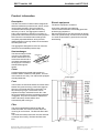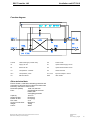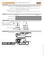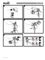
1
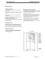
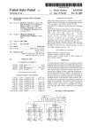
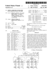
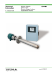
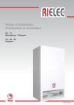
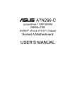
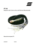
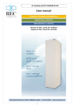
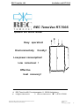
REC TemoVex AB
Ventilation unit RT-700S
REC TemoVex RT-700S
Operation and service manual
Easy operation!
Environmentally
frendly!
Low power consumption!
Low noiselevel !
Effective
heat recovery!
REC TemoVex AB, Fornminnesgatan 11, 253 68 Helsingborg
[email protected]
www.rec-indovent.se
+46 31 675500
REC TemoVex AB, Ventilation unit RT-700S, Operation and service manual
Reservation for eventually constructionchanges
Date:2010-02-19
Rev: 05
Fil: RT-700S_XT_eng.p65
1
REC TemoVex AB
Ventilation unit RT-700S
Index
Product information
3-4
Operation
5
Maintenance
6
Receiving and installation
7
Component list
8
Attachements:
Electrical wiring diagram
Belimo, throttle motor
CE-confirmation
REC TemoVex AB, Ventilation unit RT-700S, Operation and service manual
Reservation for eventually constructionchanges
Date:2010-02-19
Rev: 05
Fil: RT-700S_XT_eng.p65
2
REC TemoVex AB
Ventilation unit RT-700S
Product information
Description
Electric equipment
The REC TemoVex RT-700S model is designed for
effective ventilation of private houses, offices, nurseries and other premises. The unit contains a
counterflow heat exchanger with heat recovery
efficiency of >80 %. The aggregate consists of
body, heat exchanger in aluminium, two fans, bypass throttle valves and electrical control equipment.
REC TemoVex counterflow heat exchanger has
completely separated airflows, which prevents
leakage between incoming outdoor air and exhaust
air leaving the house.
The electric equipment consists of:
Connection cable with grounded plug.
Two fan motors with built in overheating protection
and belonging capacitors.
Electric panel with two five step switches for airflow,
switch for operation/stop, and electronic thermostat
to control the automatic by-pass function and the
after heating.
The aggregate is designed for 750 m³/h maximum
airflow at normal available pressure drop.
Heat exchanger
The heat exchanger is built
up by thin corrugated aluminium sheets which form
ducts where exhaust air is
completely separated from
the supply air. The heat is
transfered through the
sheets.
Exhaust air
Supply air
Cover
Hot dipped galvanised metal with insulation in
between. White coated front and gables. The front
door makes service easy. The cupboard is equipped
with adjustable feet.
Fans
The two fans consists of backward curved fan wheel
blades.This gives low energy consumtion (high fan
efficiency) combined with lower noise levels. The
fans are of plug in type. The air flows can be
adjusted in 5 steps, individual for each fan. If the
fans are overheated, the fans overheating protection
is triggered. The power to the fans is switched off
and the fans stop. Restart will be done
automatically after cooling of.
Filter
The unit is equipped with outdoor air filter and
exhaust air filter. The outdoor air filter, filters the
incoming air to the house. The filter has filter class
EU6.
The exhaust air filter protects the unit fans and heat
exchanger from fouling. The filter has filter class
EU3.
REC TemoVex AB, Ventilation unit RT-700S, Operation and service manual
Reservation for eventually constructionchanges
Date:2010-02-19
Rev: 05
Fil: RT-700S_XT_eng.p65
3
REC TemoVex AB
Ventilation unit RT-700S
Function diagram
H-XCH
Heat exchanger (counter flow)
S5
Power on/off
TF
Supply air fan
S1
Speed switch supply air fan
FF
Extract air fan
S2
Speed switch extract air fan
TC
Temperature controller
S4
Heater Auto/off
GT1
Temperature probe
ST1, ST2
By-Pass damper motors
S3
Max flow switch
EVB
After heater
Other technical data
Electric-heater 1,8 kW with overheating protection and
automatic by-pass function from electronic thermostat
Electricity connection 1x230 V/10 A
Dimensions (HBD):
1900, 870, 620 mm
Fans:
Centrifugal, back curved
blades, with
overheating protection
Capacity:
750 m3/h
Supply air filter :
EU 6 (bag)
Extract air filter:
EU 3 (bag)
Fire class:
A 15
Air duct connections:
Ø 200 mm
Weight:
180 kg
Colour:
White
REC TemoVex AB, Ventilation unit RT-700S, Operation and service manual
Reservation for eventually constructionchanges
Date:2010-02-19
Rev: 05
Fil: RT-700S_XT_eng.p65
4
REC TemoVex AB
Ventilation unit RT-700S
Operation
Fans
The unit is started with the start button (S1). The
electric panel contains a transformer with connections for five connected voltages.The two five-steps
switches (S2,S3) make it possible operating with 5
different air flows (voltages) for each fan.
The fan motors has built-in overheating protections,
which are activated at a too high temperature in the
motor winding.
An overheated motor is reseted automatically as the
motor is cooled off. If this is repeated often the fans
should be checked by an authorized service
technician.
If both the fans stops, the power to the ventilation
aggregate must be checked as well as the
automatic fuse (F1) behind the electric panel.
After-heater
If the temperature in the after-heater is to high
(around 90°C), the overheating protection will trigger.
With the switch for operation/stop you can switch off
the power to the ventilation aggregate. After 3
minutes , the overheating protection is automatically
reseted. The overheating can be caused by a
clogged up supply air filter, a fault in the electronic
thermostat etc.
Manual and automatic by-pass
A high indoor temperature can be lowered if bypassing the heat recovery unit, letting the colder out
door air into the room. This is easily done by
activating the by-pass function. The two by-pass
dampers are automatically controlled by the
electronic thermostat on the control panel.
Min. supply air temperature
The actual measured temperature is normally shown in
the display.
Press and keep SET-1pressed to select minimum
supply air temperature setpoint. The selected setpoint
is showned (flashing LED). The setpoint can be adjusted
up and down with the arrow buttons. Confirm selected
setpoint by pressing SET-1 shortly or wait 10s.
The selected setpoint can be checked easily by
shortly press SET-1
Active afterheating is indicated by the LED 1
(thermometer symbol above).
Max. supply air temperature:
Press and keep SET-2 pressed to select maximum
supply air temperature setpoint. The selected setpoint
is showned (flashing LED). The setpoint can be adjusted
up and down with the arrow buttons. Confirm selected
setpoint by pressing SET-2 shortly or wait 10s.
The selected setpoint can be checked easily by
shortly press SET-2
Active by-pass is indicated by the LED 2 (thermometer
symbol above).
Note !
It’s important that the ventilation aggregates temperature
adjustment is adjusted to the premises heating system.
From a general point of view the maximum supply air from the
aggregate shall be set higher than the temperature of the
house (i.e. the temperature setpoint adjustment of the heating
system of the house). This to avoid the systems to intefeer
with each other.
Example:
Minimum supply of air temerature
Maximum supply air temperature
Temperature of the heating system of the house
REC TemoVex AB, Ventilation unit RT-700S, Operation and service manual
Reservation for eventually constructionchanges
18°C
22°C
20°C
Date:2010-02-19
Rev: 05
Fil: RT-700S_XT_eng.p65
5
REC TemoVex AB
Ventilation unit RT-700S
Maintenance
Changing of filter
The exhaust air filter (bag), shall be changed 2-3
times a year.
Note! If the filter is not changed, over-pressure is created in
the house. In the long run this can give moisture damages to
the house.
The outdoor air filter has to be changed at least
twice a year.
The filters are changed by pulling them out of their
holder and replace with new.
Both filters can be ordered from REC
Temovex.Order numbers are article nr. 4871(extract)
and 4872 (supply).
Cleaning the heat exchanger
Cleaning of the heatexchanger package is normally
not needed if the unit maintenance (change of filters
etc.) has been carried out regulary.
Cleaning the heat exchanger:
Switch off power to the unit. Open the door, unscrew the
covering sheet and the cleaning shutter located at the very
bottom of the closet. Take out the plastic plug. Dismount the
exhaust and the supply air fans by loosing the electrical
connections and pull the fans out.
Spray the heatexchanger parts with a mild de-tergent, rinse
carefully with water. The water will drain out through the
condensate drainage hose.Never use high pH cleaners
containing for example ammonia or caustic in combination with
aluminium (heat exchanger package).
Cleaning the fans
Switch off the power. Loosen the screw on the
electrical connector to each fan and disconnect the
fans. The fans can now be pulled out for cleaning.
Clean with a soft brush. Re-mount in reversed order.
Condensation pipe
The water-pipe and hose for condensate shall be
controlled every year to avoid the outflow from
becoming clogged up.
REC TemoVex AB, Ventilation unit RT-700S, Operation and service manual
Reservation for eventually constructionchanges
Date:2010-02-19
Rev: 05
Fil: RT-700S_XT_eng.p65
6
REC TemoVex AB
Receiving and installation
Ventilation unit RT-700S
Supply air (to bedrooms, livingroom etc.)
Out door air (entering
the house)
Receiving control
Control that the number of parcels agrees with the
ordered and that the goods isn’t damaged by the
transport. If any transport damages, please contact
the transport company immediately.
Store the goods indoors.
Installation
The unit is intended for installation in a heated place,
such as laundry, corridor, workroom, storage room or
similar. There must be possibility for connection to a
ceespool, sink etc. connected to the sewer system.
Air ducts shall be connected on top of the aggregate,
advisably with flexible hose silencers.
Normally, supply and exhaust air ducts which is
installed in a warm place does not have to be insulated.
Extract and outdoor air ducts shall be insulated to
avoid condensation on the ducting. Supply and exhaust
air ducts located in cold areas shall be insulated with
minimum 150 mm insulation.
Exhaust air
the house)
(leaving
Extract air (from bathrooms,
kitchen etc.)
Start-up and adjustments
When the ventilation unit is installed, the aggregate
should be inspected and adjusted preferable by a
qualified installation technician.
1. Control that the fans are effected by the speed
switches.
The front of the aggregate should be easily accessible.
The aggregate has in the bottom a 3/4’’ condensation
drain for connection to the sewer system or a collecting
vessel (optional). The condense drain is needed as
condensate can be produced if the exhaust air contains
a lot of moisture. If the condensate pipe is located in a
cold place, the pipe must be well insulated.
2. Control that air ducts and details are correctly
installed, and the condensate hose is connected
draining to the sewer system. In some cases no
condansate is formed (i.e. low humidity, favourable
temperature profiles ) why the connection can be left
out.
The aggregate is adjusted in height and sideways with
adjustable rubber feet.
3. Control that supply air blows out from all room air
inlets, and all the exhaust air outlets removes air.
The unit should be connected to a earth grounded wall
socket (230V/10A).
4. Adjust the ventilation system according to the given
values stated on the ventilation drawing.
The electronic thermostats temperature probe, markt
GT1, is normally placed in the extract air duct to control
the room temperature.
The air flows can be adjusted in 5-steps, individually for
each fan.
To instead control the minimum supply inlet temperature the probe should be placed in the supply air duct
some distance from the outlet.
REC TemoVex AB, Ventilation unit RT-700S, Operation and service manual
Reservation for eventually constructionchanges
The exhaust air flow shall be 10% higher than the
supply air flow to create a moderate under-pressure in
the premises
5. Adjust the wanted temperature setpoint for the after
heater and by-pass function (see operation).
Date:2010-02-19
Rev: 05
Fil: RT-700S_XT_eng.p65
7
REC TemoVex AB
Ventilation unit RT-700S
Component list RT-700S
Model with afterheater and by-pass function (electronic
thermostat)
Position
No.
Description
Make
Type
FF
1
Extract air fan
Ziehl
RZE 250-AS47-10, 155W 0,7 A, 230V
TF
1
Supply air fan
Ziehl
RZE 250-AS47-10, 155W 0,7 A, 230V
EVB
2
Afterheater
Veab
900W, 230V
ST1,ST2
2
By-pass actuator motor
Belimo
LM230F
GT1
1
Temperature probe
DiXell
PTC S6S 1000 0hm
TC
1
Electronic thermostat
DiXell
XT120C-PTC, panel 12VAC
GT2
1
Overheating thermostat
Kienzler
Type KW 94-200º 250V 16A 80º
SK
1
Electronic relay
Crouset
GN84137111, 50-600V, 25A
T2
1
Transformer
Brugnera
153/M 230/12V
C1
2
Capacitor
Ziehl
5 uf, 400V
F1
1
Automatic fuse
Chiri PTF
250V 4AT
T1
1
Autotransformer
Lübcke
RA 131 - 27893 1.5A volt outp.
70, 90,110, 130, 150, 170, 190V
S3,S4
2
Rocker switch
General
1834 6(4)250V
S1, S2
1
5-step change-over switch Dreefs
A6CH
S5
1
On/off switch
230V, 10A, 2-pol with indicator
X1
1
Plinth socket
Extract air filter
1
Extract air filter
REC Temovex 4871, filter class EU3
Supply air filter
1
Supply air filter
REC Temovex 4872, filter class EU6
REC TemoVex AB, Ventilation unit RT-700S, Operation and service manual
Reservation for eventually constructionchanges
Comprimé
Date:2010-02-19
Rev: 05
Fil: RT-700S_XT_eng.p65
8
Technical data sheet
Damper actuator LM230A
Damper actuator for operating
air control dampers in ventilation
and air-conditioning systems for
building services installations
• For air control dampers up to
approx. 1 m2
• Torque 5 Nm
• Nominal voltage AC 100 ... 240 V
• Control: Open-close or 3-point
Technical data
Electrical data
Functional data
Nominal voltage
Nominal voltage range
Power consumption In operation
At rest
For wire sizing
Connection
AC 100 ... 240 V, 50/60 Hz
AC 85 ... 265 V
1.5 W @ nominal torque
0.4 W
4 VA
Cable 1 m, 3 x 0.75 mm2
Torque (nominal torque)
Direction of rotation
Manual override
Running time
Sound power level
Position indication
Min. 5 Nm @ nominal voltage
or 1
Reversible with switch 0
Gearing latch disengaged with pushbutton,
self-resetting
Max. 95° , limited on both sides
by means of adjustable, mechanical end stops
150 s
Max. 35 dB (A)
Mechanical, pluggable
Protection class
Degree of protection
EMC
Low voltage directive
Mode of operation
Ambient temperature range
Non-operating temperature
Ambient humidity range
Maintenance
II Totally insulated
IP54 in any mounting position
CE according to 89/336/EEC
CE according to 73/23/EEC
Type 1 (to EN 60730-1)
–30 ... +50°C
–40 ... +80°C
95% r.H., non-condensating (EN 60730-1)
Maintenance-free
Dimensions
Weight
See «Dimensions» on page 2
Approx. 500 g
Angle of rotation
Safety
Dimensions / Weight
Safety notes
!
• The damper actuator is not allowed to be used outside the specified field of application,
especially not in aircraft or any other form of air transport.
• Caution: Power supply voltage !
• Assembly must be carried out by trained personnel. Any legal regulations or regulations
issued by authorities must be observed during assembly.
• The device may only be opened at the manufacturer‘s site. It does not contain any parts
that can be replaced or repaired by the user.
• The cable must not be removed from the device.
• When calculating the required torque, the specifications supplied by the damper
manufacturers (cross section, design, installation site), and the air flow conditions must
be observed.
• The device contains electrical and electronic components and is not allowed to be disposed
of as household refuse. All locally valid regulations and requirements must be observed.
1
Open-close damper actuator AC 230 V, 5 Nm
LM230A
Product features
Simple direct mounting
Manual override
Adjustable angle of rotation
High functional reliability
Simple direct mounting on the damper spindle with a universal spindle clamp, supplied with
an anti-rotation strap to prevent the actuator from rotating.
Manual operation is possible with the self-resetting pushbutton (the gearing latch remains
disengaged as long as the pushbutton is pressed).
Adjustable angle of rotation with mechanical end stops.
The actuator is overload-proof, requires no limit switches and automatically stops when the
end stop is reached.
Accessories
Electrical accessories
Mechanical accessories
Description
Data sheet
Auxiliary switch S..A..
Feedback potentiometer P..A..
T2 - S..A..
T2 - P..A..
Shaft extension AV6-20
T2 - Z-LM..A..
Electrical installation
Wiring diagrams
Open-close control
N
Note
3-point control
L1
N
L1
!
• Caution: Power supply voltage !
• Other actuators can be connected in parallel.
Please note the performance data.
0
1
Direction of rotation
2
1
3
2
3
0
0
1
1
0
1
Dimensions [mm]
47
61
Dimensional drawings
66
116
Damper spindle
Length
6 ... 20
22
94
41
Data sheet T2-LM230A • en • v1.3 • 04.2005 • Subject to modifications
min. 37
2
2
1
37
6 ... 20
>6
< 20
3
4
6 Nm
10
10
70214-00001.C
LM..A.. / TM..A..
1
1 mm
1
2
5
2
65°
www.belimo.com
1
Z-PI
1
LM..A.. / TM..A..
~
~
T
T
+
L1
–
N
+
L1
–
N
0
2
3
0
1
T
~
~
T
~
!
–
+
~
AC 24 V / DC 24 V
1
2
3
1
2
3
–
+
+
+
S1 S2 S3
T
0
1
1
DC 48 ... 110 V
(LM72A..)
1
3
–
~
2
+
~
1
0
1
2
3
+
S1 S2 S3
0
0...100%
LM24A.. LMC24A..
LM72A.. TMC24A..
AC 100 ... 240 V
!
LM24A-S.. TMC24A-S..
N
L1
L1
N
L1
L1
1
2
3
1
2
3
LM24AP5..
1
S1 S2 S3
S1 S2 S3
0
1
0...100%
2
3
DC 0…10 V
DC 2…10 V
5
LM24A-SR.. LMC24A-SR..
LM24A-MF.. TMC24A-SR..
!
N
L1
T
DC 48 ... 110 V
(LM72A-SR..)
1
2
1
3
1
2
DC 0…10 V
DC 2…10 V
5
LM72A-SR..
!
N
L1
T
AC 100 ... 240 V
1
2
1
Y
U5
2
3
Y
U
+
3
DC 0…10 V
MP
5
LM24A-MP..
Y
U5
2
–
AC 24 V / DC 24 V
(LM24A-V / VR..)
T
T
~
1
Y
U
+
0
–
~
–
T
AC 24 V / DC 24 V
S1 S2 S3
LM230A-S.. TMC230-S..
~
LM230A.. LMC230A..
TMC230A..
1
1
2
+
DC 0…10 V
DC 2…10 V
VR..
5
LM24A-V
LM230ASR..
2
LM230A-V / VR..
www.belimo.com
EG-FÖRSÄKRAN OM ÖVERENSSTÄMMELSE
EC/EEA DECLARATION OF CONFORMITY
Undertecknad representerande följande tillverkare The undersigned, representing the
following manufacturer
REC Temovex® AB
Fornminnesgatan 11
+46 31 675500
+46 42 202238
Namn Name:
Adress Address:
Telefon Telephone no:
Telefax Facsimile no:
försäkrar härmed att produkt herewith declares that the product
materialslag type of equipment:
Ventilationsvärmeväxlare Air to air heat
exchangers for ventilation
RT-700S
modell/typ model/type:
överensstämmer med bestämmelserna i följande EG-direktiv is in conformity with the
provisions of the following EC directives
Referens nr reference no
Titel title
73/23/EEG
93/68/EEG
Lågspänningsdirektivet(LVD) Low Voltage
directive (LVD)
89/392/EEG
91/368/EEG
93/44/EEG
93/68/EEG
Maskindirektivet (MD) Machinery directive
89/336/EEG
92/31/EEG
93/68/EEG
Direktivet för elektromagnetisk kompatibilitet (EMC)
Electromagnetic Compatibility (EMC-directive)
Helsingborg 2005-07-01
Lennart Skoglund, Verkställande Direktör Managing Director