1
IRIS Workstation Guide
Version 1.0
Silicon Graphics, Inc.
Mountain View
California 94043
Documentation:
Daniel Sears
Marcia Allen
Robin Bristow
Diane Wilford
Drawings:
Annette Whelan
©
Copyright 1984, Silicon Graphics, Inc.
This document contains proprietary information of
Silicon Graphics, Inc., and is protected by Federal
copyright law. The information may not be
disclosed to third parties or copied or duplicated in
any form, in whole or in part, without prior written
consent of Silicon Graphics, Inc.
IRIS Workstation Guide Version 1.0
Document Number: 5001-092-001-0
CONTENTS
1. Introduction
1
2. Unpacking the IRIS Workstation Components
3
3. IRIS
3.1
3.2
3.3
3.4
3.5
3.6
Workstation Specifications
Hardware Components
Ethernet Equipment
Cables
Monitor
IRIS Control Panel
Monitor Control Panel
Monitor Back Panel
Cabinet
Power Switch
Cabinet I/O Panel
Cabinet Power Panel
Power Switch
Documentation
5
5
5
7
7
7
9
9
11
11
11
13
13
13
4. Hardware Installation
4.1 Keyboard to Monitor Connection
4.2 Mouse to Monitor Connection
4.3 Monitor to Cabinet Video Connections
4.4 Monitor to Cabinet Control Cable Connection
4.5 Monitor to Cabinet AC Power Cable Connection
4.6 IRIS Workstation to Serial Line Connection
Terminal Connection
Modem Connection
Printer Connection
4.7 IRIS Workstation to Ethernet Connection
4.8 Cabinet AC Power Connection
4.9 Cabinet to Dial and Switch Box Connection
15
15
15
15
17
17
17
17
18
18
18
19
19
5.
Operation
5.1 Boot
5.2 Demonstration Programs
5.3 Monitor Adjustment
5.4 Network Software
5.6 Shutdown
21
21
22
23
24
25
6. System Administration
6.1 Startup
Automatic Disk Drive Boot
Automatic Tape Drive Boot
PROM Monitor
6.2 Boot Checkout Information
27
27
27
28
28
29
-i-
6.3
6.4
6.5
6.6
6.7
6.8
6.9
6.10
6.11
6.12
6.13
6.14
UNIX Single-User Mode
File Systems and fsck(1M)
Configuring UNIX on an IRIS Workstation
Configuration Files
Naming an IRIS Workstation
Adding a New Account
Connecting an ASCII Terminal to the IRIS Workstation
Connecting a Modem to the IRIS Workstation
Connecting a Printer to the IRIS Workstation
Enabling a Network Connection to the IRIS Workstation
Tape Drive
Shutdown
Crash Recovery
Appendix A: Configuration Switches
29
32
32
32
34
34
36
38
39
40
41
41
42
45
Appendix B: F sck- The Unix File System Check Program 47
Appendix C: Diagnostics
71
Appendix D: The C/FORTRAN Interface
75
Appendix E: IRIS Floating Point
89
Appendix F: Manual Pages
99
1
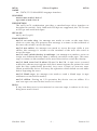
Appendix H: IRIS Workstation RS-232 Interface
127
Appendix I: UUCP Administration
131
Appendix J: OEM Kernel Generation for the IRIS Workstation
141
Appendix K: The IRIS Terminal Programming Environment
147
Appendix L: GL 1 and GL 1.9 Software Differences
155
- ii -
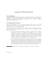
1. Introduction
This document explains how to install, test and operate an IRIS Workstation.
It contains step-by-step procedures for installing the components that make up
an IRIS Workstation. This document should be read carefully before installing
an IRIS Workstation.
The IRIS Workstation components are delivered assembled and ready for
connection with cables provided in the delivery cartons. The basic outline of
the installation is as follows:
• Planning and Site Selection
• Unpacking the IRIS Workstation Components
• Hardware Installation
• Operation and Testing
Silicon Graphics provides a comprehensive product support and maintenance
program for the IRIS Workstation. For further information, the toll-free
Geometry Hotline numbers for Silicon Graphics Customer Service are:
Silicon Graphics Customer Service
Version 1.0
(800) 252-0222
North America (except California)
(800) 345-0222
California
2 IRIS WORKSTATION GUIDE
Introduction
Version 1.0
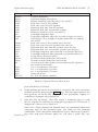
2. Unpacking the IRIS Workstation Components
The IRIS Workstation system is shipped in two reinforced cardboard cartons.
One contains the Electronics Cabinet and the other contains the Monitor and
other components. Each component is delivered assembled and ready for
connection with the cables provided in the IRIS Workstation delivery cartons.
If additional equipment or spare parts are ordered, they will be shipped in
additional cartons.
Before installation, the delivery cartons should be inspected for damage. If any
of the cartons or their contents appear damaged, contact the carrier and Silicon
Graphics Customer Service (see Section 1). After inspection, move the cartons
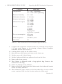
to the installation site. See Table 2-1 for a list of guidelines for site selection.
Although site selection is the customer ’s responsibility, Silicon Graphics
representatives will provide consulting services upon request.
1. Inspect the delivery cartons for damage.
WARNING: The delivery cartons should be moved on a pallet jack
or cart capable of supporting 200 lbs. If they must be lifted, two
strong people are needed.
WARNING: Do not turn the delivery cartons on edge.
2. Move the cartons to the installation site.
3. Cut the plastic straps on the brown carton.
4. Cut the tape that seals the top of the carton, open the carton and
remove the tray containing the Keyboard, Mouse, cables and other
equipment.
5. Remove the foam spacers covering the Monitor.
6. Remove the carton by lifting it up and off the base pallet.
7. The Monitor is shipped inside a large plastic bag. Remove the
Monitor from the bag and place it on the table where it will be used.
WARNING: Do not attempt to pick up the Monitor by the white
plastic inserts on the sides.
8. Check for damage to the Monitor.
Version 1.0
4 IRIS WORKSTATION GUIDE
Unpacking the IRIS Workstation Components
Category
IRIS 1400
Temperature
50 — 86F° (operating)
40 — 176F° (non-operating)
Relative humidity
40 — 80%
Minimum clearance
3” all sides
Monitor desk space
36” width
30” length
Cabinet floor space
24” width
33” length
29” height
Power
115 volts
15 amps
60 hertz
single phase
two wires + ground
Power consumption
883 watts
1240 KVA
Heat dissipation
3012 BTU/hour
Card slots
20
Table 2-1: IRIS Workstation Environmental Specifications
9. Compare the equipment included in the tray with the list in Section
3. If any parts appear to be missing, contact Silicon Graphics
Customer Service (see Section 1).
10. Cut the plastic straps on the white carton.
11. Open the top of the carton and remove the foam cap.
12. Lift the carton off of the Cabinet.
13. Lift the Cabinet off the base pallet and set it on the floor.
14. Remove the foam spacers.
15. The Cabinet is shipped inside a large plastic bag. Remove the
Cabinet from the bag.
16. Check for damage to the Cabinet.
17. Remove the front panel from the Cabinet and check that the boards
inside are firmly attached.
18. The Cabinet has four castors on its base that allow it to be rolled
across a surface. Roll it to the location where it will be used.
Version 1.0
3. IRIS Workstation Specifications
Component
IRIS 1400 Cabinet
Monitor
Keyboard
Mouse
Transceiver
Height
Width
Length
29.0”
18.0”
1.5”
1.0”
2.0”
18.0”
20.0”
19.0”
2.0”
7.0”
27.0”
21.0”
8.5”
3.0”
4.0”
Weight
200.0 lbs
97.0 lbs
5.0 lbs
0.5 lbs
0.8 lbs
Table 3-1: IRIS Workstation Component Specifications
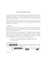
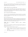
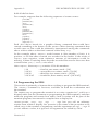
3.1 Hardware Components
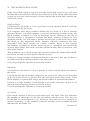
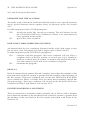
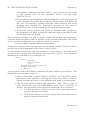
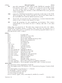
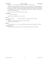
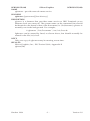
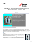
Each IRIS Workstation system has four hardware components (see Figure 3-1).
• The Electronics Cabinet is a floor-standing unit with a 20-slot backplane
and a power supply. The Cabinet uses forced air cooling and is
mounted on casters.
• The Monitor is a high-resolution 19-inch color monitor.
• The Keyboard is an 83-key up-down encoded keyboard.
• The Mouse is a 3-button mouse.
• The Switch Box has 32 independently programmable switches and 32
independently programmable LED indicator lights. An 8 character
LED display gives status information for the Dial Box and the
Switch Box.
• The Dial Box (optional) has 8 independently programmable valuators
for sending analog information to an application program for the
IRIS Terminal.
3.2 Ethernet Equipment
The IRIS Workstation can be connected to an Ethernet local area network with
an Ethernet transceiver and drop cable.
• The Ethernet Transceiver connects the IRIS Workstation to the
Ethernet.
Version 1.0
6 IRIS WORKSTATION GUIDE
IRIS Workstation Specifications
Figure 3-1: IRIS Workstation System
Version 1.0
IRIS WORKSTATION GUIDE
IRIS Workstation Specifications
7
• 1 15-conductor drop cable connects the Cabinet to an Ethernet
transceiver.
3.3 Cables
Each IRIS Workstation is supplied with a cable set for connecting the IRIS
Workstation components.
• 4 bundled, color-coded, coaxial video cables connect the video
output of the Cabinet to the Monitor.
• 1 25-conductor control cable connects the Cabinet to the Monitor.
This cable sends and receives signals between the Cabinet and the
Mouse, Keyboard and Reset button on the IRIS Control Panel.
• 2 10-foot, 3-wire, grounded AC power cables provide power for the
Monitor and Cabinet.
• 1 37-pin flat cable connects the Dial Box to the Switch Box.
• 1 9-pin cable connects the Switch Box to
Panel.
Port 4
on the Cabinet I/O
• 1 3-wire AC power cable provides power for the Dial Box and the
Switch Box.
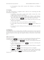
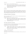
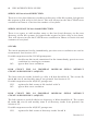
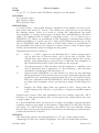
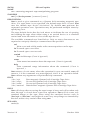
3.4 Monitor
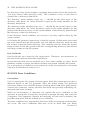
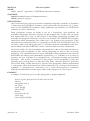
The Monitor has two control panels, the IRIS Control Panel on the front left
and the Monitor Control Panel on the front right. On the back of the Monitor
are several ports for receiving video signals, a power socket and a control cable
port.
IRIS Control Panel
The IRIS Control Panel has two ports for connecting the Keyboard and Mouse
to the Monitor, a Reset button and two indicator lights (see Figure 3-2).
• 1 DIN socket labeled
to the Monitor.
Keyboard
is a port for connecting the Keyboard
• 1 slide-locking D socket labeled
Mouse to the Monitor.
• 1 LED labeled
on.
Power
• 1 LED labeled
Halt
Mouse
is a port for connecting the
indicates that power for the Cabinet is switched
indicates that the processor is stopped.
• 1 Reset button is located on the IRIS Control Panel. Pressing this
button resets the processor which in turn resets the rest of the
system. After the Reset button has been pressed, the IRIS
Version 1.0
8 IRIS WORKSTATION GUIDE
IRIS Workstation Specifications
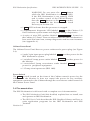
Figure 3-2: IRIS Control Panel and Monitor Control Panel
Version 1.0
IRIS WORKSTATION GUIDE
IRIS Workstation Specifications
9
Workstation must be rebooted. This switch and the Halt light
correspond to the Reset button and Halt light on the I/O Control
Panel on the Cabinet. Either button may be used.
WARNING: Do not press the Reset button
while the IRIS Workstation is running UNIX.
If the IRIS Workstation is not running UNIX
and is under control of the PROM Monitor,
then the Reset buttons or the Power switches
may be used. See the discussion on Crash
Recovery in Section 6.14.
Monitor Control Panel
The Monitor Control Panel has several features for adjusting the Monitor (see
Section 5.3) and a Power switch for the Monitor (see Figure 3-2).
• 1 knob labeled Brightness adjusts the white and black levels equally.
Turning this knob clockwise increases the Monitor ’s brightness.
• 1 knob labeled Contrast adjusts the white levels. Turning this knob
clockwise increases the Monitor ’s contrast.
• 1 button labeled
demagnetizes the Monitor screen.
Degauss
• 1 light labeled Health indicates that power for the Monitor is
switched on and most of the Monitor is operating properly.
• 1 switch labeled
Power
controls power for the Monitor.
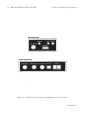
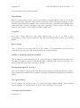
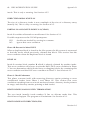
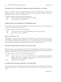
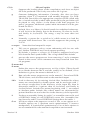
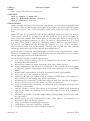
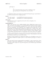
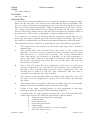
Monitor Back Panel
The Monitor Back Panel has several ports that connect the Monitor to the
Cabinet (see Figure 3-3).
• 2 BNC sockets labeled Ext
connection from the Cabinet.
• 2 BNC sockets labeled
• 2 BNC sockets labeled
Cabinet.
V D
R
Sync
are used for the video sync
are not used.
receive the red video signal from the
• 2 BNC sockets labeled
Cabinet.
G
receive the green video signal from the
• 2 BNC sockets labeled
Cabinet.
B
receive the blue video signal from the
• 1 5-amp fuse.
• 1 10-amp 100/120 volt power plug provides power for the Monitor
from the Cabinet.
Version 1.0
10 IRIS WORKSTATION GUIDE
IRIS Workstation Specifications
Figure 3-3: Monitor Back Panel
Version 1.0
IRIS WORKSTATION GUIDE
IRIS Workstation Specifications
11
• 1 25-pin plug for connecting a control cable from the Cabinet to the
Monitor.
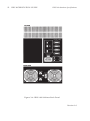
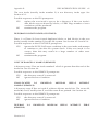
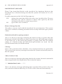
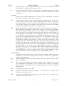
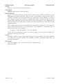
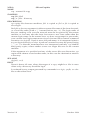
3.5 Cabinet
There are two control panels on the back of the IRIS 1400 Cabinet: an I/O Panel
and a Power Panel. A Power switch controls power for the IRIS Workstation
system.
Power Switch
The Power switch for the IRIS 1400 Workstation is located beside the tape drive
slot on the front upper-left corner of the Cabinet.
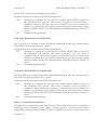
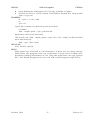
Cabinet I/O Panel
The Cabinet I/O Panel has ports for connecting the Cabinet to the Monitor and
a host computer (see Figure 3-4) and several control and indicator features.
•
•
Port 1 is the receptacle for the control cable that is connected
between the Monitor Back Panel and the Cabinet I/O Panel.
Port 2
lines.
,
Port 3
and
Port 4
• 1 15-pin D socket labeled
an Ethernet drop cable.
are available for RS-232 or RS-423 serial
Ethernet
connects the IRIS Workstation to
• 1 BNC socket labeled Sync is a port for the video sync cable
connecting the Cabinet and the Monitor.
• 1 BNC socket labeled Red is a port for transmitting the red video
signal from the Cabinet to the Monitor through a coaxial cable.
• 1 BNC socket labeled Green is a port for transmitting the green video
signal from the Cabinet to the Monitor through a coaxial cable.
• 1 BNC socket labeled Blue is a port for transmitting the blue video
signal from the Cabinet to the Monitor through a coaxial cable.
• 1 Reset button is located on the Cabinet I/O Panel. Pressing this
button resets the processor which in turn resets the rest of the
system. After the Reset button has been pressed, the IRIS
Workstation must be rebooted. This switch and the Halt light
correspond to the Reset button and Halt light on the IRIS Control
Panel on the Monitor. Either button may be used.
Version 1.0
12 IRIS WORKSTATION GUIDE
IRIS Workstation Specifications
Figure 3-4: IRIS 1400 Cabinet Back Panel
Version 1.0
IRIS Workstation Specifications
IRIS WORKSTATION GUIDE
13
WARNING: Do not press the Reset button
while the IRIS Workstation is running UNIX.
If the IRIS Workstation is not running UNIX
and is under control of the PROM Monitor,
then the Reset buttons or the Power switches
may be used. See the discussion on Crash
Recovery in Section 6.14.
• 1
Halt
LED indicates that the processor is stopped.
• 1 alphanumeric diagnostic LED labeled Status on the Cabinet I/O
Panel indicates system status and displays startup diagnostics.
• A series of nine DIP switches labeled Configuration is located on
the Cabinet I/O Panel. These switches control the IRIS Workstation’s
host serial line baud rate, startup diagnostics and boot environment
(see Appendix A).
Cabinet Power Panel
The Cabinet Power Panel has two power outlets and a power plug (see Figure
3-4).
• 1 male 3-pin input power plug labeled
IRIS Workstation system.
• 1 switched 2-amp power outlet labeled
the Monitor.
Power
provides power for the
Monitor
provides power for
• 1 unswitched 3-amp convenience outlet labeled
power for peripheral equipment.
3A Max
provides
• 1 15-amp circuit protector (IRIS 1400).
Power Switch
The Power switch located on the front of the Cabinet controls power for the
Cabinet and the Monitor. It does not control the power for any auxiliary
equipment connected to the Cabinet through the convenience outlet located on
the Cabinet Power Panel.
3.6 Documentation
The IRIS Workstation is delivered with a complete set of documentation.
• The IRIS Workstation Guide (this booklet) explains how to install, test
and operate an IRIS Workstation.
• The IRIS User’s Guide describes the IRIS Graphics Library and how to
write application programs for the IRIS Workstation and IRIS
Terminal.
Version 1.0
14 IRIS WORKSTATION GUIDE
IRIS Workstation Specifications
• The C and FORTRAN editions of the IRIS Graphics Library are quick
reference cards with overviews of each command in the IRIS
Graphics Library.
• The UNIX Programmer’s Manual is a set of reference manuals and
tutorials for the UNIX System.
Version 1.0
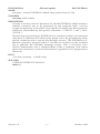
4. Hardware Installation
This section describes how to install and connect the components that make up
an IRIS Workstation system (see Figure 4-1). Prior to installation, each
component should be unpacked and placed near its final location. Since the
IRIS Workstation components are delivered assembled, they only need to be
connected with the cables provided in the delivery cartons.
WARNING: Do not connect the IRIS Workstation to an
external power source until each cable has been
connected and checked.
4.1 Keyboard to Monitor Connection
The Keyboard cable is connected to the IRIS Control Panel located on the lower
left front of the Monitor (see Figure 3-2).
1. Connect the DIN plug on the Keyboard cable to the DIN socket
labeled Keyboard on the IRIS Control Panel.
4.2 Mouse to Monitor Connection
The Mouse cable is connected to the IRIS Control Panel located on the lower
left front of the Monitor (see Figure 3-2).
1. Connect the slide-locking D socket on the Mouse cable to the D plug
labeled Mouse on the IRIS Control Panel.
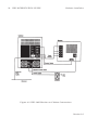
4.3 Monitor to Cabinet Video Connections
The color-coded bundle of coaxial video cables is connected between the
Cabinet I/O Panel and the Monitor Back Panel (see Figures 3-3, 3-4 and 4-1).
1. For single Monitor operation, set all of the input impedance switches
to the 75 Ω position.
If several Monitors are connected in a series (daisy chain), set the
input impedance switches to the High position for all but the last
Monitor, which should be set to the 75 Ω position.
2. Connect each cable end to an input socket on the Monitor Back
Panel. Since they are identical, either socket can be used.
Version 1.0
16 IRIS WORKSTATION GUIDE
Hardware Installation
Figure 4-1: IRIS 1400 Monitor to Cabinet Connections
Version 1.0
Hardware Installation
IRIS WORKSTATION GUIDE
17
3. Push each cable into its connector and rotate its lock into place.
4. Connect the other end of each color-coded cable to the corresponding
output socket on the Cabinet I/O Panel.
5. Push the cable into the connector and rotate the lock into place.
4.4 Monitor to Cabinet Control Cable Connection
The Control Cable connects the Cabinet and the Monitor.
1. Connect the female end of the Control Cable to the 25-pin socket on
the Monitor Back Panel.
2. Connect the male end of the Control Cable to
I/O Panel.
Port 1
on the Cabinet
3. Fix the Control Cable into place by tightening the captive screws on
each side of both plugs.
4.5 Monitor to Cabinet AC Power Cable Connection
The Monitor power outlet is located on the Cabinet Power Panel (see Figure 34).
This switched AC outlet is controlled by the Cabinet Power switch.
1. Connect the female end of the AC power cable to the
socket on the Monitor Back Panel.
Input
power
2. Connect the male end of the Monitor power cable to the AC outlet
labeled Monitor on the Cabinet Power Panel.
4.6 IRIS Workstation to Serial Line Connection
The IRIS Workstation can be connected to a modem, a terminal or a printer
through a serial line attached to Port 2 , Port 3 or Port 4 on the Cabinet I/O
Panel. The connection for each of these devices are slightly different. Each
physical device connection also has a corresponding UNIX software
configuration procedure. Sections 6.8, 6.9 and 6.10 describe these procedures.
Terminal Connection
1. Attach an RS-232 cable from the ASCII terminal to Port 2 , Port 3 or
Port 4 on the Cabinet I/O Panel. Appendix H has a description of
the RS-232 interface for the IRIS Workstation serial ports. These are
Data Terminal Equipment (DTE) type RS-232 ports. If the ASCII
terminal is also DTE type, then a null modem is required for the
connection. If the terminal is Data Communication/Circuit Terminating
Equipment (DCE) type, then a simple connection can be made
without a null modem. The manual for the ASCII terminal should
have a specification of its RS-232 interface.
Version 1.0
18 IRIS WORKSTATION GUIDE
Hardware Installation
2. Turn on the power for the ASCII terminal.
3. See Section 6.8 for instructions on how to enable a serial port for
a terminal. This involves editing system configuration files and
resetting the software that enables the serial port on the IRIS
Workstation.
Modem Connection
1. Attach an RS-232 cable from the modem to Port 2 , Port 3 or Port 4
on the Cabinet I/O Panel. Appendix H has a description of the RS232 interface for the IRIS Workstation serial ports.
2. Turn on the power for the modem.
3. See Section 6.9 for instructions on how to enable a serial port for
a modem. This involves editing system configuration files and
resetting the software that enables the serial port on the IRIS
Workstation.
Printer Connection
1. Attach an RS-232 cable from the printer to Port 2 , Port 3 or Port 4
on the Cabinet I/O Panel. Appendix H has a description of the RS232 interface for the IRIS Workstation serial ports. The manual for
the printer should have a specification for its RS-232 interface.
2. Turn on the power for the printer.
3. See Section 6.10 for instructions on how to enable a serial port
for a printer. This involves editing system configuration files and
resetting the software that enables the serial port on the IRIS
Workstation.
4.7 IRIS Workstation to Ethernet Connection
The IRIS Workstation can communicate with other hosts and terminals through
an Ethernet local area network. The IRIS Workstation can be connected to an
Ethernet local area network while the network is operating.
1. Select an appropriate tap point on the Ethernet coaxial cable.
NOTE: Approved Ethernet coaxial cable is marked with rings at 8.2
foot intervals. Transceivers should be placed at these rings to
minimize the chance of transceiver reflections with phase angles that
add and cause transmission errors.
2. Tap into the Ethernet cable (instructions are included with each
transceiver).
Version 1.0
Hardware Installation
IRIS WORKSTATION GUIDE
19
3. Connect the transceiver to the Ethernet cable.
4. Connect the male end of the drop cable to the Ethernet port on the
Cabinet I/O Panel.
5. Connect the female end of the drop cable to the transceiver.
4.8 Cabinet AC Power Connection
The Cabinet power socket is located on the Cabinet Power Panel.
CAUTION: Do not connect the IRIS Workstation to a
switched power outlet.
1. Connect the female end of the AC power cable to the power socket
on the Cabinet Power Panel (see Figure 3-4).
2. Connect the male end of the Cabinet power cable to an appropriate
outlet. See Table 2-1 for a specification of the power requirements
of the IRIS Workstation.
4.9 Cabinet to Dial and Switch Box Connection
The IRIS Workstation can be connected to an optional Dial and Switch Box for
sending information to an application program on the IRIS Workstation.
1. Connect the 37-pin flat cable from the port on the Dial Box to the
bottom left port on the Switch Box.
2. Connect the 9-pin cable from the top left port on the Switch Box to
Port 4 on the Cabinet I/O Panel. This RS-232 cable should be
enabled in the following way. Edit the file /etc/inittab. Each line
corresponds to a device file in /dev and contains four fields separated
by colons. Find the line for port d3 and put a x in the second field.
This prevents a getty process from being run on the port.
3. Plug the 3-wire AC power cable on the Switch Box into the
convenience outlet on the Cabinet Power Panel.
Version 1.0
3A Max
20 IRIS WORKSTATION GUIDE
Hardware Installation
Version 1.0
5. Operation
The IRIS Workstation is a graphics-oriented micro-computer. To the user, it
looks like a standard System V UNIX computer. The sections that follow
outline the normal operation procedures used with the IRIS Workstation.
These include a simple boot procedure, login, compiling and running
demonstration programs, adjusting the Monitor, using the network software
and shutdown. Normally, the boot and shutdown procedures are handled by
the system administrator. They are covered here in outline form only.
The IRIS Workstation can be configured by the customer in many ways. These
include adding new accounts, new terminals and printers and connecting it to
a local area network. See Section 6 for an explanation of system administration
for the IRIS Workstation.
NOTE: The sections that follow assume that the reader
has some experience with the UNIX system as a user.
5.1 Boot
The IRIS Workstation can be booted in many different ways but the simplest
and most common is to boot off of a disk.
NOTE: UNIX single-user mode should be used only for
system maintenance. Normal operation should occur only
in multi-user mode.
1. Check the configuration switches on the I/O Panel on the rear of the
Cabinet (see Figure 3-4). Switches 4 through 7 should be in the
Closed position. Switch 8 should be in the Open position.
2. Turn on the power for the IRIS Workstation.
3. These steps will boot the IRIS Workstation in single-user mode. A
UNIX prompt will appear.
#
4. The file system will be checked automatically during the boot
process to insure their integrity. fsck is mostly automatic. If fsck
finds anything out of the ordinary, it will prompt the user for a
decision. See Section 6 and Appendix B or consult with the system
administrator.
Version 1.0
22 IRIS WORKSTATION GUIDE
Operation
5. Start multi-user mode with the multi command.
# multi
...
6. Set the date.
CAUTION: It is important to accurately set
the date since many system programs depend
on the time. Also, several user programs like
make determine their actions based on the
relative dates of files. Accurate system time is
even more important for program development
distributed across a network.
The input format of the date command is “mmddhhmmyy” [monthday-hour-minute-year(optional)]. For example,
Is the date Wed Mar 21 14:16:42 PST 1984? (y or n) n
Enter the correct date: 0322091484
Is the date Thu Mar 22 09:14:01 PST 1984? (y or n) y
...
If the time zone appears to be incorrect, see Section 6.5 and TZ(4).
A UNIX login prompt should then appear.
7. Log into a UNIX account. The IRIS Workstation is shipped with
three user accounts: rootcsh, root and guest. The rootcsh account is a
privileged account with a C Shell environment. The root account is
a privileged account with a Bourne Shell environment. The guest
account is a sample user account with a C Shell environment. New
accounts can be added by the system administrator (see Section 6.7).
login: guest
8. Accounts frequently have passwords for protection. Enter the
password.
password:
...
The password’s characters will not be echoed onto the terminal
screen. Note that the guest does not have a password. See passwd(1)
and Section 6.7 for information on how to add or change a password
for an account.
5.2 Demonstration Programs
After the IRIS Workstation has been booted, it can be tested by running the
demonstration programs included in the directory /usr/demos. These include
some simple programs like particles and some more sophisticated programs like
flight. To run any of these programs, simply type its name. For example,
Version 1.0
IRIS WORKSTATION GUIDE
Operation
23
$ cd /usr/demos
$ particles 15
...
runs the particles program. In this demonstration program, 15 particles are set in
random motion in a cube. When one of the particles touches a boundary of the
cube, it emits a square bubble that inflates to a certain size and then pops.
Generally, these demonstration programs can be exited by typing
clear the screen of graphics “leftovers”, type the command gclear.
CONTROL
-c. To
The IRIS User’s Guide documents the IRIS Graphics Library, the software that a
programmer uses to write applications for the IRIS Workstation. In the second
section of that manual, the IRIS Graphics Library, there are a few sample
programs that illustrate how the graphics software is used. On page 2-57 of
that manual, there is a program listing for a program called track. This program
can be compiled and run on the IRIS Workstation. For example,
$ cc track.c -o track -Zg
See cc(1) for information on the C and FORTRAN compilers for the IRIS
Workstation.
After track has been compiled, it can be run.
$ track
A blue box will appear on the screen which can be moved around with the
Mouse. To exit track, press all three Mouse buttons or CONTROL -c.
5.3 Monitor Adjustment
The Monitor Control Panel on the right side of the Monitor has several knobs for adjusting the brightness and contrast of the Monitor.
NOTE: Color rendering and stability may drift for the
first 45 minutes after startup.
1. After the Monitor has warmed up, adjust the Brightness control
knob until the gray raster is barely brighter than the black areas on
the edge of the screen. Lighter brightness settings will impair image
sharpness and color fidelity.
2. For optimum clarity, turn the Contrast control knob to the maximum
(clockwise) setting and then turn it back slightly.
3. If the color purity or convergence appear to be out of adjustment,
hold down the Degauss button on the Monitor Control Panel for
about 10 seconds and then release it. The image should then
improve noticeably.
Version 1.0
24 IRIS WORKSTATION GUIDE
Operation
5.4 Network Software
The IRIS Workstation has three programs for using an Ethernet local area
network: xcp, xx and xlogin. These simple commands allow the user to copy
files from one host to another, run commands on a remote host and log into a
remote host.
Here is a brief explanation of certain terms associated with networks.
• A network is a collection of computers and terminals connected by
some means.
• A host is a computer on a network.
• A local host is the host that a person is using.
• A remote host is the opposite of a local host. That is, it is a machine
on a network that a person is not using. The difference between a
local and a remote host is the frame of reference one uses. The local
host is where the user is and remote host is “where” the user isn’t.
xcp copies file from one host (either local or remote) to another (also either local
or remote). Here are some examples:
$ xcp sqiral.c olympus:/oh4/doc/install/sqiral.c
$ xcp sting:/usr/include/stdio.h te
$ xcp puppy:temp_vi sting:temp_vi
NOTE: In each example, the user must have an account
with the same user name on each host.
The first example copies a file in the current directory of the remote machine
to the file sqiral.c in the directory /oh4/doc/install on the host named olympus. The
second example copies a file from the host olympus to the local machine. The
third example copies a file from one remote machine named puppy to another
named sting.
The second command xx is useful for running short
host. Again, this command assumes that the user
remote machine with the same user name as on
example, it may be useful to find what the load
machine:
commands on a remote
has an account on the
the local machine. For
average is on another
$ xx olympus uptime
1:51pm up 21:14. 30 users. load average: 12.14 11.34 10.25
The third command xlogin allows the user to login across a network on a remote
host. All that is needed is a host name. For example,
$ xlogin olympus
login:
...
For more information about the network software for the IRIS Workstation, see
the manual entries in Appendix F.
Version 1.0
IRIS WORKSTATION GUIDE
Operation
5.5 Shutdown
25
The IRIS Workstation should not be left on indefinitely. However, since the
Monitor has a long warmup period, the IRIS Workstation should be left on
continuously during work hours.
WARNING: Do not press either Reset button or the
Power switch while the IRIS Workstation is running
UNIX without first using the /etc/reboot -q command listed
below. If the IRIS Workstation is under the control of the
PROM Monitor, then the Reset buttons and the Power
switch may be safely used.
1. To shut down UNIX, type the /etc/reboot -q command.
$ /etc/reboot -q
NOTE: /etc/reboot -q is a privileged command,
requiring super-user permission.
2. Set the
Version 1.0
Power
switch on the Cabinet to the
Off
position.
26 IRIS WORKSTATION GUIDE
Operation
Version 1.0
6. System Administration
The system administrator is responsible for configuring the IRIS Workstation to
meet local requirements. The sections that follow explain how to boot the IRIS
Workstation, check the file system, configure UNIX, add new accounts, add
ASCII terminals and modems, make backups, shutdown the IRIS Workstation
and recover from a crash.
This document uses the standard UNIX convention for refering to entries in the
UNIX reference manual. The entry name is followed with a section number in
parentheses. For example, cc(1) refers to the cc manual entry in Section 1 in the
UNIX Programmer’s Manual.
6.1 Startup
Startup options can be selected by setting certain configuration switches on the
Cabinet Back Panel. These switches control the environment the IRIS
Workstation will be booted from and the display of checkout information about
the boot state (see Appendix A).
The IRIS Workstation can be booted from either a disk drive or a tape drive.
These devices can be used automatically or explicitly through the PROM
Monitor. Automatic boot procedures involve setting configuration switches
and turning on the system power. The PROM Monitor is a simple command
interpreter through which all boot environments can be accessed. The user
gives a PROM Monitor command that specifies the boot device.
NOTE: If a non-existent device is specified as a boot
environment, then the IRIS Workstation will ignore the request
and wait to be reset.
Automatic Disk Drive Boot
If the Boot Environment configuration switches are set to “00001”, the IRIS
Workstation will search for and read a boot file named defaultboot in the root file
system after the system power is turned on.
1. Set the Boot Environment configuration switches (switches 4 through
8) to “00001” where “0” means Closed and “1” means Open . See
Appendix A.
Version 1.0
28 IRIS WORKSTATION GUIDE
2. Set the
Power
switch on the Cabinet to the
System Administration
On
position.
A variation of this boot procedure can be used explicitly through the PROM
Monitor. See the entries for the PROM Monitor d command in Table 6-1.
Automatic Tape Drive Boot
If the Boot Environment configuration switches are set to “10000”, the IRIS
Workstation will search for and read a boot file named defaultboot from the tape
drive. The IRIS Workstation will be booted automatically after the system
power is turned on.
NOTE: If the IRIS Workstation is to be booted from a
tape drive, the tape must be in cpio(1) format.
1. Set the Boot Environment configuration switches (switches 4 through
8) to “10000” where “0” means Closed and “1” means Open . See
Appendix A.
2. Set the
Power
switch on the Cabinet to the
On
position.
A variation of this boot procedure can be used explicitly through the PROM
Monitor. See the entries for the PROM Monitor tb command in Table 6-1.
PROM Monitor
The PROM Monitor is a simple command interpreter through which each IRIS
Workstation boot environment can be accessed. If the Boot Environment
configuration switches are set to “01000”, the IRIS Workstation will be under
the control of the PROM Monitor when the system power is turned on.
1. Set the Boot Environment configuration switches (switches 4 through
8) to “01000” where “0” means Closed and “1” means Open . See
Appendix A.
2. Set the
Power
switch on the Cabinet to the
On
position.
3. The PROM Monitor prompt should appear on the IRIS Monitor
screen. If it doesn’t, press the Halt button on either the IRIS
Control Panel on the front of the Monitor or the I/O Panel on the
back of the Cabinet.
iris>
4. Boot the UNIX kernel.
iris> d
...
This command causes the IRIS Workstation to search for and read a
boot file named defaultboot in the root file system.
Version 1.0
IRIS WORKSTATION GUIDE
System Administration
29
Since the IRIS Workstation can be booted from different environments (hard
disks, tape drives, etc.) it may be useful to find the names of the files on a tape
or disk before booting the IRIS Workstation. This information can be found
with the PROM Monitor. For example,
iris> d *
bin
defaultboot
dev
iris>
etc
lib
lost+found
stand
tmp
unix
unix1
usr
version
searches the root file system and lists its contents. After locating a file, it can be
booted explicitly with the d command. For example,
iris> d unix
...
See Table 6-1 for a list of the commands available through the PROM Monitor.
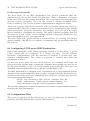
6.2 Boot Checkout Information
If the Checkout configuration switch (switch 3) is set to the Open position, the
IRIS Workstation will display additional information during system startup.
• Scan processor memory. An “X” is displayed for each half megabyte
of memory and a “.” is displayed for each non-existent half megabyte
of memory.
• Clear processor memory.
• Map processor memory.
• Display configuration switch values.
This information is intended for diagnostic purposes only. Normally the
Checkout configuration switch should be set to the Closed position.
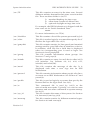
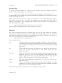
6.3 UNIX Single-User Mode
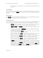
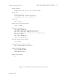
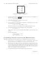
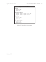
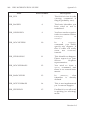
After the IRIS Workstation has been booted, it will display some system
information. See Figure 6-1 for an example. This includes information about the
software release, memory size, hardware configuration and the file system.
NOTE: UNIX single-user mode should be used only for
system maintenance. Normal operation should occur
only in multi-user mode.
Initially the IRIS Workstation is booted in UNIX single-user mode. The
following procedure starts multi-user mode and sets the date. The important
file for starting multi-user mode is /etc/rc. It contains commands for starting
daemons and mounting file systems. See brc(1).
Version 1.0
30 IRIS WORKSTATION GUIDE
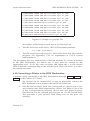
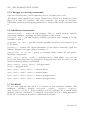
Command
System Administration
Description
h
Display a list of PROM Monitor commands.
t
Enter serial interface to host.
n
Boot file over a network.
[file]
Boot defaultboot from a disk. Similar to the Disk Drive
Boot procedure.
d
d
[file]
Boot file from a disk.
d
[pathname]/*
List the contents of directory pathname.
Boot defaultboot from a tape drive. The file must be in cpio
format. Similar to the Tape Drive Boot procedure.
tb
tb
[file]
Boot file from a tape drive. The file must be in cpio
format.
tb *
List the contents of a tape in cpio format.
r
Restart the PROM Monitor.
Table 6-1: PROM Monitor Commands
1. Start multi-user mode.
# multi
2. Set the date. The input format of the date command is
“mmddhhmmyy”
[month-day-hour-minute-year(optional)].
For
example,
Is the date Wed Mar 21 14:16:42 PST 1984? (y or n) n
Enter the correct date: 0322091484
Is the date Thu Mar 22 09:14:01 PST 1984? (y or n) y
...
A UNIX login prompt will then appear.
3. Log into a UNIX account. The IRIS Workstation is shipped with
three user accounts: rootcsh, root and guest. The rootcsh account is a
privileged account with a C Shell environment. The root account is
a privileged account with a Bourne Shell environment. The guest
account is a sample user account with a C Shell environment. New
accounts may be added by the system administrator (see Section
6.7).
login:
...
Version 1.0
System Administration
IRIS WORKSTATION GUIDE
Kernel Number:
SYSTEM 5 UNIX #135: [Fri May 4 11:15:09 PST 1984]
Release ID:
Release: Beta-1.5
(C) Copyright 1983 - UniSoft Corporation
(C) Copyright 1983 - Silicon Graphics Inc.
Kernel Size:
kmem = 290816
Approximate Available Memory:
avail = 1282048
Hardware Configuration:
dsd at mbio 0x1f00 ipl 1
qic0 (QIC Quarter Inch Cartridge Tape) slave 0
md0 (Vertex V170 Name: XORN drive 0) slave 0
md1 (Vertex V170 Name: Beta Version 1.2 (4/10/84) slave 1
mf0 not installed
nx0 at mbio 0x0010 ipl 2
ge0 at mbio 0x1400 ipl 4
fbc0 at mbio 0x1c00 ipl 3
Root File System Device Name:
root on md0a
Swap Space Device Name and Size:
swap on md0b (8865K of swap space)
Single-User Mode Banner:
INIT: SINGLE USER MODE
Silicon Graphics Inc.
IRIS 1400 Workstation
Single-User Prompt:
#
Figure 6-1: IRIS Workstation Boot Information
Version 1.0
31
32 IRIS WORKSTATION GUIDE
System Administration
File Systems and fsck(1M)
The disk drive on an IRIS Workstation has several partitions that are
represented by device files in the /dev directory. Three of them are of interest
to the user: the root file system (/dev/md0a), the swap space (/dev/swap) and the
/usr file system (/dev/md0c). The root file system is always mounted when
UNIX is running. The /usr file system is unmounted in single-user mode.
These file systems should be checked with fsck before multi-user mode is
started and the other file systems are mounted. fsck is an interactive file system
check and repair program. Generally, fsck prompts for a yes or a no reply
before altering a corrupted file system. The most common problem that fsck
discovers is a bad i-node count resulting from an improper shutdown. For
more information on fsck, see Appendix B.
The files /.login and /.profile contain a command line for running fsck during
system startup. The file /etc/rc contains a command line for mounting the /usr
file system.
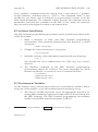
6.4 Configuring UNIX on an IRIS Workstation
One of the strengths of the UNIX operating system is its flexibility. A given
UNIX system can be configured in a variety of ways. Choices include
hardware configurations, like the amount of memory a system has, and
software configurations, like where a program is located and who has
permission to use it.
On the user level, there are even more choices. For example, each user can
choose how the system finds commands, whether other people can use his or
her files and whether or not to override certain system defaults. Each user can
establish an environment that he or she feels comfortable with.
The IRIS Workstation is shipped with a minimum set of non-standard system
defaults. Each system administrator can then configure the IRIS Workstation to
suit the needs of the local user community and each user can then fine tune his
or her personal environment.
NOTE: The discussion that follows assumes that the
reader understands UNIX system administration. For
more information, see the UNIX Programmer’s Manual.
The sections that follow contain instructions for common system administration
tasks for the IRIS Workstation.
6.5 Configuration Files
There are several files in the directories /etc and /usr that may or should be
edited by the IRIS Workstation system administrator.
Version 1.0
IRIS WORKSTATION GUIDE
System Administration
/etc/TZ
33
This file contains an entry for the time zone. Several
different utilities determine their time zone from this
file. There are three fields in /etc/TZ:
1) standard heading for time zone,
2) offset from Greenwich Mean Time,
3) optional daylight savings time zone.
For example, the IRIS Workstation is shipped with the
time zone set for Pacific Standard Time.
PST8PDT
For more information, see TZ(4).
/etc/checklist
This file contains a list of file systems processed by fsck
/etc/cshrc
This file is read at login by accounts that specify the C
Shell as the login shell. See csh(1).
/etc/gettydefs
This file contains entries for line speeds and terminal
settings used by getty(1M) when it initializes a device.
In addition, each line has a field that is displayed
when its corresponding port is used to login. See
Sections 6.8 and gettydefs(4).
/etc/group
This file contains information about groups. See
Section 6.7 and group(4).
/etc/inittab
This file contains an entry for each device that init(1)
will initialize. See Sections 6.8, 6.9, 6.10, 6.11,
inittab(4) and telinit(1M).
/etc/motd
This file contains the message of the day. It is
displayed each time a user logs into an IRIS
Workstation.
/etc/passwd
This file contains information about people who have
accounts on an IRIS Workstation. See Section 6.7 and
passwd(4).
/etc/profile
This file is read at login by accounts that specify the
Bourne Shell as the login shell. See sh(1).
/etc/rc
This command file is read by init(1) at the
start of multi-user mode. Typically, it is used to start
daemons and run other commands at system startup.
See brc(1).
/etc/sys_id
This file contains the name of the system. See Section
6.6, hostname(1) and sys_id(4).
/etc/termcap
This file contains entries for different terminal types.
See Section 6.8 and termcap(4).
Version 1.0
34 IRIS WORKSTATION GUIDE
System Administration
/etc/ttytype
This file maps terminal types to devices attached to an
IRIS Workstation. See Sections 6.8, 6.11, tset(1) and
ttytype(4).
/usr/lib/crontab
This file contains entries for commands to be run at
fixed intervals by the cron(1M) daemon. See cron(1M).
/usr/lib/uucp/L-devices This file contains line speed entries for each port used
by uucp(1). See Section 6.9.
/usr/lib/uucp/L.sys
This file contains information about sites that uucp(1)
can communicate with. See Section 6.9.
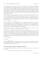
6.6 Naming an IRIS Workstation
Each IRIS Workstation is shipped with the name IRIS. To change this, edit the
file /etc/sys_id, insert a new name and reboot the system. Be sure that there are
no blanks in the name and that it is fewer than 14 characters long.
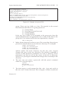
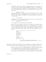
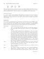
6.7 Adding a New Account
New accounts can be created on the IRIS Workstation by adding a line to the
file /etc/passwd. Additionally, the system administrator can set up the new user ’s
environment with startup files, home directories, etc. These are largely matters
of personal taste and will not be covered here except in outline form.
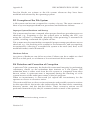
1. Edit the file /etc/passwd. This file contains a line for each account on a
UNIX system. Each line has seven fields separated by colons (:). See
passwd(4).
1)
2)
3)
4)
5)
6)
7)
Account Name
Encrypted User Password
User Number
Group Number
Name
Home Directory (default /)
Login Shell (default /bin/sh)
Figure 6-2 contains an example /etc/passwd file.
Add a line for the new account. Be sure that it contains a group
number and a unique account name and user number. The home
directory should be specified in the sixth field. The login shell
should be specified in the seventh field. For example, to add an
account for a user named peter the following line might be inserted:
peter::10:20:Peter Broadwell:/usr/staff/peter:/bin/csh
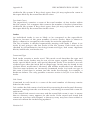
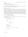
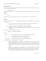
2. Edit the file /etc/group to include the new user in any additional
groups. Entries to this file are optional. See group(4). Figure 6-3
contains an example /etc/group file. Each line corresponds to a
Version 1.0
IRIS WORKSTATION GUIDE
System Administration
35
root::0:0:Superuser:/:/bin/csh
rootcsh::0:0:Superuser:/:/bin/csh
rootsh::0:0:Superuser:/:/bin/sh
daemon:*:1:1::/:
bin:*:2:2:Binary Files:/:
uucp:*:3:5:UUCP Login Account:/usr/spool/uucpPublic:/usr/lib/uucp/uucico
adm:*:5:3:Administration:/usr/adm:
uucpadm:*:8:8:UUCP Administration:/usr/lib/uucp:
lp:*:9:9:Line Printer:/:
guest::998:998::/usr/people/guest:/bin/csh
Figure 6-2: Sample /etc/passwd File
group. There are four fields to a line. The asterisk in the second
field indicates that there is no group password.
1)
2)
3)
4)
Group Name
Encrypted Group Password
Group Number
Group Members
If the new user wishes to be included in the group adm, then the
system administrator can append the user ’s name to the line for the
group adm. User names in this field are separated by commas.
adm:*:3:henry,peter
3. Make a home directory for the new user. The ownership, file and group
protections should also be set for the new directory. For example,
$
$
$
$
mkdir
chgrp
chmod
chown
/usr/staff/peter
user /usr/staff/peter
755 /usr/staff/peter
peter /usr/staff/peter
mkdir(1) makes the home directory for the new user. chgrp(1)
changes the group of the new directory. The chmod(1) command is
used to set the protection parameters on a file or directory. These
parameters can also be set by the owner of the file or directory.
chown(1) is a privileged command that changes the ownership of the
directory.
4. The new user can create a password with the passwd command
when he or she first logs in.
$ passwd
New password:
Re-enter new password:
$
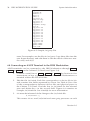
5. The final step is to add startup files like .cshrc, .login and .profile in
the new user ’s home directory. This is largely a matter of personal
Version 1.0
36 IRIS WORKSTATION GUIDE
System Administration
sys:*:0:
system:*:0:
daemon:*:1:
bin:*:2:
adm:*:3:
sgi_use:*:4:
uucp:*:5:uucp
sgi_use:*:6:
sgi_use:*:1:
uucpadm:*:8:uucp
lp:*:9:
sgi_use:*:10:
sgi_use:*:11:
sgi_use:*:12:
sgi_use:*:13:
sgi_use:*:14:
sgi_use:*:15:
sgi_use:*:16:
sgi_use:*:11:
sgi_use:*:18:
sgi_use:*:19:
guest:*:998:
games:*:999:
user:*:20:
Figure 6-3: Sample /etc/group File
taste. For examples, see the files in /usr/guest. Copy these files into the
new home directory and edit them to suit the needs of the new user.
See csh(1) and sh(1).
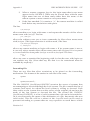
6.8 Connecting an ASCII Terminal to the IRIS Workstation
ASCII terminals can be connected to the IRIS Workstation through
Port 3 or Port 4 on the Cabinet I/O Panel (see Figure 3-4).
Port 2
,
1. Connect a serial line to Port 2 , Port 3 or Port 4 . See Section 4.6 for
instructions on how to physically connect the IRIS Workstation to a
terminal with an RS-232 serial line.
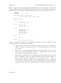
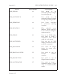
2. Edit the file /etc/inittab. Each line corresponds to a device file in /dev
and contains four fields separated by colons. See Table 6-2 for a list
of the correspondences between device files and physical ports on
the Cabinet I/O Panel. Find the line in /etc/inittab for the selected
port and delete the x in the second field. Figure 6-4 contains an
example /etc/inittab file. See inittab(4) for more information.
3. init must be informed of the change to the /etc/inittab file.
$ /etc/telinit -q
This causes init to read /etc/inittab and start getty processes on each
Version 1.0
IRIS WORKSTATION GUIDE
System Administration
File
Description
console
floppy
kmem
md0a
md0c
md1a
md1c
mem
mt1
nrtape
null
Console terminal.
Optional floppy disk drive.
Kernel memory (used by ps(1)). See mem(7).
Disk zero root (/) file system.
Disk zero usr (/usr) file system.
Optional disk one first file system.
Optional disk one second file system.
Memory (used by ps(1)). See mem(7).
Cartridge magnetic tape.
Cartridge magnetic tape (no rewind on open or close).
Null device (zero length on input, data sink on output).
See null(7).
Disk zero root (/) file system (raw device).
Disk zero usr (/usr) file system (raw device).
Optional disk one first file system (raw device).
Optional disk one second file system (raw device).
Cartridge magnetic tape (treated as a blocked device).
Cartridge magnetic tape (treated as a blocked device).
Swap device (used by ps(l)).
System console (linked to /dev/console).
System console (linked to /dev/console).
A synonym for the tty device associated with a process.
See termio(7) and tty(7).
Port 2 on Cabinet I/O Panel.
Port 3 on Cabinet I/O Panel
Port 4 on Cabinet I/O Panel.
Network ports.
IP/TCP for future releases.
rmd0a
rmd0c
rmd1a
rmd1c
rmt1
rqic
swap
syscon
systty
tty
ttyd1
ttyd2
ttyd3
ttyn*
EXOS/*
37
Table 6-2: Special Device Files in /dev
port selected in /etc/inittab.
4. If the default speed set in /etc/inittab is incorrect, the user can select
another speed by pressing the BREAK key. The line speed choices for
each port are set in the file /etc/gettydefs. See gettydefs(4). Figure 6-5
contains an example /etc/gettydefs file.
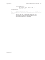
5. Edit the file /etc/ttytype. This file maps a terminal type to each
device. Figure 6-6 contains an example /etc/ttytype file. Each port is
mapped to a device as in Table 6-2.
Each user ’s Shell startup file should have tset commands that read
/etc/ttytype and set the terminal type. See Table 6-3 for example
commands. These should be included in each C Shell (csh (1)) user ’s
.login file and each Bourne Shell (sh (1)) user ’s .profile file. See
Version 1.0
38 IRIS WORKSTATION GUIDE
System Administration
is:s:initdefault:
fp::sysinit:/etc/fload >/dev/console 2>&1
bl::bootwait:/etc/bcheckrc </dev/console >/dev/console 2>&1 #bootlog
bc::bootwait:/etc/brc 1>/dev/console 2>&1 #bootrun command
sl::wait:(rm -f /dev/syscon;ln /dev/systty /dev/syscon;) 1>/dev/console 2>&1
rc::wait:/etc/rc 1>/dev/console 2>&1 #run com
pf::powerfail:/etc/powerfail 1>/dev/console 2>&1 #power fail routines
co::respawn:/etc/getty console co_9600
d1:x:respawn:/etc/getty ttyd1 dx_9600
d2:x:respawn:/etc/getty ttyd2 dx_9600
d3:x:respawn:/etc/getty ttyd3 dx_9600
n1:x:respawn:/etc/getty ttyn1 dx_9600
n2:x:respawn:/etc/getty ttyn2 dx_9600
Figure 6-4: Sample /etc/inittab File
tset(1) and ttytype(4).
6. If necessary, edit the file /etc/termcap to contain entries for terminals
not described there. See termcap(4).
7. Login on the ASCII Terminal.
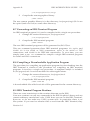
6.9 Connecting a Modem to the IRIS Workstation
A modem can be connected to the IRIS Workstation through Port 2 , Port 3 or
Port 4 on the Cabinet I/O Panel. This modem can then be used by the UNIX
utilities cu and uucp. Port 3 should be used first since the serial line
configuration files are prepared for it. To attach a modem to any of the other
ports requires modification of the serial line configuration files.
1. See Section 4.6 for instructions on how to physically connect the
IRIS Workstation to a modem with an RS-232 serial line.
2. Edit the file /etc/inittab. Each line corresponds to a device file in /dev
and contains four fields separated by colons. See Table 6-2 for a list
of the correspondences between device files and physical ports.
Find the line for the selected port and put an x in the second field.
This prevents a getty process from being started on the port. See
inittab(4).
3. init must be informed of the change to the /etc/inittab file.
$ /etc/telinit -q
This causes init to read /etc/inittab and enable ports for modem use.
4. Edit the file /usr/lib/uucp/L-devices. This file contains line speed entries
for each port. See Section 1.3 for a description of the fields in each
line of /usr/lib/uucp/L-devices.
5. Edit the file /usr/lib/uucp/L.sys. This file contains information about
sites that uucp can communicate with. See Section 1.3 for a
Version 1.0
IRIS WORKSTATION GUIDE
System Administration
39
co_9600# B9600 # B9600 SANE TAB3 #\r\n\nIRIS login: #co_4800
co_4800# B4800 # B4800 SANE TAB3 #\r\n\nIRIS login: #co_2400
co_2400# B2400 # B2400 SANE TAB3 #\r\n\nIRIS login: #co_1200
co_1200# B1200 # B1200 SANE TAB3 #\r\n\nIRIS login: #co_300
co_300# B300 # B300 SANE TAB3 #\r\n\nIRIS login: #co_9600
dx_9600# B9600 # B9600 SANE TAB3 #\r\n\nIRIS login: #dx_9600
dx_4800# B4800 # B4800 SANE TAB3 #\r\n\nIRIS login: #dx_4800
dx_1200# B1200 # B1200 SANE TAB3 #\r\n\nIRIS login: #dx_1200
du_1200# B1200 # B1200 SANE TAB3 #\r\n\nIRIS login: #du_300
du_300# B300 # B300 SANE TAB3 #\r\n\nIRIS login: #du_1200
Figure 6-5: Sample /etc/gettydefs File
description of the fields in each line of /usr/lib/uucp/L.sys.
6. Test the serial line with cu(1C), the UNIX terminal emulator.
$ cu -s1200 -lttyd3 9603515
7. Test the serial line with uucp(1C), the UNIX serial line file transfer
program. See Appendix I for an explanation of UUCP system
administration.
The procedure above is intended for a dial-out modem. To connect a modem
to the IRIS Workstation for dial-in use, a getty must be started on the
appropriate port. To do this, edit /etc/inittab and delete the x in the second
field of the line corresponding to the selected port. Then run telinit -q to have
init reread /etc/inittab.
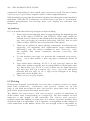
6.10 Connecting a Printer to the IRIS Workstation
A printer can be connected to the IRIS Workstation through
Port 4 on the Cabinet I/O Panel.
Port 2
,
Port 3
or
1. See Section 4.6 for instructions on how to physically connect the
IRIS Workstation to a printer with an RS-232 serial line.
2. Edit the file /etc/inittab. Each line corresponds to a device file in /dev
and contains four fields separated by colons. See Table 6-2 for a list
of the correspondences between device files and physical ports.
Find the line for the selected port and put an x in the second field.
This prevents a getty process from being run on the port. See
inittab(4).
Version 1.0
40 IRIS WORKSTATION GUIDE
iris
iris
iris
v50am
du
du
v50am
v50am
System Administration
systty
console
syscon
ttyd2
ttyd3
ttyd4
ttyn1
ttyn2
Figure 6-6: Sample /etc/ttytype File
3. Link the device file for the printer port to /dev/lp. For example, to
link the device file for Port 3 ,
# ln /dev/ttyd3 /dev/lp
4. Make the printer port writable to every user.
# chmod 666 /dev/lp
5. If the printer has XON/XOFF capabilities, initialize the port with
stty. See stty(1). For example,
# (stty -ixon ; sleep 100000) < /dev/lp
This line should then be added to the system startup file /etc/rc.
6. init must be informed of the change to the /etc/inittab file.
$ /etc/telinit -q
This causes init to read /etc/inittab and enable a port for the line
printer.
7. Test the line printer.
# cat /etc/passwd > /dev/lp
# lpr /etc/passwd
# pr -f -l66 /etc/rc | lpr
6.11 Enabling a Network Connection to the IRIS Workstation
The IRIS Workstation can be connected to an Ethernet local area network.
1. See Section 4.7 for instructions on how to physically connect the
IRIS Workstation to an Ethernet local area network network.
2. Edit the file /etc/inittab. Each line corresponds to a device file in /dev
and contains four fields separated by colons. See Table 6-2 for a list
of the correspondences between device files and physical ports.
Find the line for the selected port and delete the x in the second
field. See inittab(4) for more information.
3. init must be informed of the change to the /etc/inittab file.
Version 1.0
IRIS WORKSTATION GUIDE
System Administration
C Shell (.login)
set noglob
set temp=(‘tset -Q -S’)
setenv TERM $temp[1]
setenv TERMCAP “$temp[2]”
unset temp
unset noglob
41
Bourne Shell (.profile)
eval ‘tset -Q -s’
Table 6-3: tset Commands for Startup Files
$ /etc/telinit -q
This causes init to read /etc/inittab and enable ports for network
login.
4. Edit the file /etc/ttytype. This file maps each device to a terminal type.
See Figure 6-6 for an example /etc/ttytype file. Each network port is
mapped to a device as in Table 6-2.
Each user ’s Shell startup file should have tset commands that read
/etc/ttytype and set the terminal type. See Table 6-3 for example
commands. These should be included in each C Shell (csh (1)) user ’s
.login file and each Bourne Shell (sh (1)) user ’s .profile file. See
tset(1) and ttytype(4).
5. Login through the network to another host.
6.12 Tape Drive
The IRIS Workstation has an optional tape drive for backing up file systems on
the disks and for reading new software distributions. See Table 6-4 for a list of
tape drive specifications. In addition, the IRIS Workstation can be booted from
the tape drive in case the root file system is damaged beyond repair (see
Section 6.1).
The tape drive can be used with either tar(1) or cpio(1), the standard UNIX
archiving tools. cpio is slightly favored. The tape boot procedure mentioned in
Section 6.1 requires a tape in cpio format. Keep a copy of the root file system
on tape to ensure that there is a reliable copy in the event of a bad crash. See
Table 6-5 for some UNIX commands for using the tape drive. See tar(1) and
cpio(1).
6.13 Shutdown
The IRIS Workstation should not be left on indefinitely. However, since the
Monitor has a long warmup period, the IRIS Workstation should be left on
continuously during work hours.
Version 1.0
42 IRIS WORKSTATION GUIDE
System Administration
Tape Drive Specifications
Device Name:
Density:
Speed:
Tape Lengths:
Suppliers:
/dev/rmt1
10,000 flux changes per inch
l00K per foot
90 inches per second
300 and 450 feet
3M/Scotch
Data Electronics, Inc.
Table 6-4: Tape Drive Specifications
WARNING: Do not press either Reset button or the
Power switch while UNIX is running without first using
the /etc/reboot -q command. If the IRIS Workstation is
under the control of the PROM Monitor, then the Reset
buttons and the Power switch may be safely used.
1. To shut down UNIX, type /etc/reboot -q.
$ /etc/reboot -q
2. Set the
NOTE: /etc/reboot -q is a privileged command
requiring super-user permission.
Power
switch on the Cabinet to the
Off
position.
6.14 Crash Recovery
This section is necessarily incomplete. See Appendix C for a list of error
messages and probable causes. If the IRIS Workstation stops running for some
reason, first try to reboot it without hitting the Reset button. Use the
/etc/reboot -q command.
$ /etc/reboot -q
If keystrokes are not echoed, or for some other reason it is not possible to shut
down the system gently, press the Reset button and hope that the file systems
aren’t damaged.
The next step is to boot the system with the normal boot procedure. During
the boot procedure, the file check program fsck will be run and will display
information about the state of the file system. (Appendix B explains how to use
fsck; crash(8) is a manual entry with advice on recovering from a crash.)
Version 1.0
IRIS WORKSTATION GUIDE
System Administration
Tape Drive Procedures
Backup
$ cpio -oha1 .
$ tar -cv .
Incremental Backup
$ find . -mtime -7 -print | cpio -oha1
$ find . -mtime -7 -print | tar -cv -
Read Tape
$ cpio -ihum1
$ tar -xv
List Tape Contents
$ cpio -iht1
$ cpio -ihtv1
$ tar -tv
Table 6-5: Tape Drive Procedures
Version 1.0
43
44 IRIS WORKSTATION GUIDE
System Administration
Version 1.0
Appendix A: Configuration Switches
Switch
Name
Position
1-2
Serial line
00
01
10
11
3
Checkout
0
1
4-8
Boot environment
1
00000
00001
00100
01000
01100
10000
all others
Meaning
300 baud
19,200 baud
1200 baud
9600 baud
No additional testing.
Additional testing (time-consuming).
Floppy disk boot.
Disk boot.
Network boot.
PROM Monitor.
Serial line boot.
Tape boot.
Undefined.
Table A-1: IRIS Workstation Configuration Switches
1. 0 means Closed and 1 means Open .
Version 1.0
46 IRIS WORKSTATION GUIDE
Appendix A:
Version 1.0
Appendix B: Fsck-The Unix File System Check Program1
B.1 Introduction
When a Unix operating system is brought up, a consistency check of the file
systems should always be performed. This precautionary measure helps to
insure a reliable environment for file storage on disk. If an inconsistency is
discovered, corrective action must be taken. No changes are made to any file
system by fsck without prior operator approval.
The purpose of this memo is to dispel the mystique surrounding file system
inconsistencies. It first describes the updating of the file system (the calm
before the storm) and then describes file system corruption (the storm).
Finally, the set of heuristically sound corrective actions used by fsck (the Coast
Guard to the rescue) is presented.
B.2 Update of the File System
Every working day hundreds of files are created, modified, and removed.
Every time a file is modified, the Unix operating system performs a series of
file system updates. These updates, when written on disk, yield a consistent
file system. To understand what happens in the event of a permanent
interruption in this sequence, it is important to understand the order in which
the update requests were probably being honored. Knowing which pieces of
information were probably written to the file system first, heuristic procedures
can be developed to repair a corrupted file system.
There are five types of file system updates. These involve the super-block,
inodes, indirect blocks, data blocks (directories and files), and free-list blocks.
Super-Block
The super-block contains information about the size of the file system, the size
of the inode list, part of the free-block list, the count of free blocks, the count
1. This appendix is modified from a paper with the same name by T. J. Kowalski.
Version 1.0
48 IRIS WORKSTATION GUIDE
Appendix B:
of free inodes, and part of the free-inode list.
The super-block of a mounted file system (the root file system is always
mounted) is written to the file system whenever the file system is unmounted
or a sync command is issued.
Inodes
An inode contains information about the type of inode (directory, data, or
special), the number of directory entries linked to the inode, the list of blocks
claimed by the inode, and the size of the inode.
An inode is written to the file system upon closure1 of the file associated with
the inode.
Indirect Blocks
There are three types of indirect blocks: single-indirect, double-indirect and
triple-indirect. A single-indirect block contains a list of some of the block
numbers claimed by an inode. Each one of the 256 entries in an indirect block
is a data-block number. A double-indirect block contains a list of singleindirect block numbers. A triple-indirect block contains a list of double-indirect
block numbers.
Indirect blocks are written to the file system whenever they have been
modified and released2 by the operating system.
Data Blocks
A data block may contain file information or directory entries. Each directory
entry consists of a file name and an inode number.
Data blocks are written to the file system whenever they have been modified
and released by the operating system.
First Free-List Block
The super-block contains the first free-list block. The free-list blocks are a list
of all blocks that are not allocated to the super-block, inodes, indirect blocks, or
data blocks. Each free-list block contains a count of the number of entries in
this free-list block, a pointer to the next free-list block, and a partial list of free
blocks in the file system.
1.
All in core blocks are also written to the file system upon issue of a sync system call.
2.
More precisely, they are queued for eventual writing. Physical I/O is deferred until the
buffer is needed by UNIX or a sync command is issued.
Version 1.0
Appendix B:
IRIS WORKSTATION GUIDE
49
Free-list blocks are written to the file system whenever they have been
modified and released by the operating system.
B.3 Corruption of the File System
A file system can become corrupted in a variety of ways. The most common of
these ways are improper shutdown procedures and hardware failures.
Improper System Shutdown and Startup
File systems may become cormpted when proper shutdown procedures are not
observed, e.g., forgetting to sync the system prior to halting the CPU, not
using the /etc/reboot -q command, physically write-protecting a mounted file
system, or taking a mounted file system off-line.
File systems may become further corrupted if proper startup procedures are not
observed, e.g., not checking a file system for inconsistencies, and not repairing
inconsistencies. Allowing a corrupted file system to be used (and, thus, to be
modified further) can be disastrous.
Hardware Failure
Any piece of hardware can fail at any time. Failures can be as subtle as a bad
block on a disk pack, or as blatant as a non-functional disk-controller.
B.4 Detection and Correction of Corruption
A quiescent3 file system may be checked for structural integrity by performing
consistency checks on the redundant data intrinsic to a file system. The
redundant data is either read from the file system or computed from other
known values. A quiescent state is important during the checking of a file
system because of the multi-pass nature of the fsck program.
When an inconsistency is discovered fsck reports the inconsistency for the
operator to choose a corrective action.
This section tells how to discover inconsistencies and possible corrective actions
for the super-block, the inodes, the indirect blocks, the data blocks containing
directory entries, and the free-list blocks. These corrective actions can be
performed interactively by the fsck command under control of the operator.
3. i.e., unmounted and not being written on.
Version 1.0
50 IRIS WORKSTATION GUIDE
Appendix B:
Super-Block
One of the most common corrupted items is the super-block. The super-block
is prone to corruption because every change to the file system’s blocks or
inodes modifies the super-block.
The super-block and its associated parts are most often corrupted when the
computer is halted and the last command involving output to the file system
was not a sync command.
The super-block can be checked for inconsistencies involving file-system size,
inode-list size, free-block list, free-block count, and the free-inode count.
File-System Size and Inode-List Size.
The file-system size must be larger than the number of blocks used by the
super-block and the number of blocks used by the list of inodes. The number
of inodes must be less than 65,535. The file-system size and inode-list size are
critical pieces of information to the fsck program. While there is no way to
actually check these sizes, fsck can check for them being within reasonable
bounds. All other checks of the file system depend on the correctness of these
sizes.
Free-Block List.
The free-block list starts in the super-block and continues through the free-list
blocks of the file system. Each free-list block can be checked for a list count out
of range, for block numbers out of range, and for blocks already allocated
within the file system. A check is made to see that all the blocks in the file
system were found.
The first free-block list is in the super-block. Fsck checks the list count for a
value of less than zero or greater than fifty. It also checks each block number
for a value of less than the first data block in the file system or greater than the
last block in the file system. Then it compares each block number to a list of
already allocated blocks. If the free-list block pointer is non-zero, the next
free-list block is read in and the process is repeated.
When all the blocks have been accounted for, a check is made to see if the
number of blocks used by the free-block list plus the number of blocks claimed
by the inodes equals the total number of blocks in the file system.
If anything is wrong with the free-block list, then fsck may rebuild it, excluding
all blocks in the list of allocated blocks.
Free-Block Count.
The super-block contains a count of the total number of free blocks within
the file system. Fsck compares this count to the number of blocks it found free
Version 1.0
Appendix B:
IRIS WORKSTATION GUIDE
51
within the file system. If they don’t agree, then fsck may replace the count in
the super-block by the actual free-block count.
Free-Inode Count.
The super-block contains a count of the total number of free inodes within
the file system. Fsck compares this count to the number of inodes it found free
within the file system. If they don’t agree, then fsck may replace the count in
the super-block by the actual free-inode count.
Inodes
An individual inode is not as likely to be corrupted as the super-block.
However, because of the great number of active inodes, there is almost as
likely a chance for corruption in the inode list as in the super-block.
The list of inodes is checked sequentially starting with inode 1 (there is no
inode 0) and going to the last inode in the file system. Each inode can be
checked for inconsistencies involving format and type, link count, duplicate
blocks, bad blocks, and inode size.
Format and Type.
Each inode contains a mode word. This mode word describes the type and
state of the inode. Inodes may be one of four types: regular inode, directory
inode, special block inode, and special character inode. If an inode is not one
of these types, then the inode has an illegal type. Inodes may be found in one
of three states: unallocated, allocated, and neither unallocated nor allocated.
This last state indicates an incorrectly formatted inode. An inode can get in
this state if bad data is written into the inode list through, for example, a
hardware failure. The only possible corrective action is for fsck is to clear the
inode.
Link Count.
Contained in each inode is a count of the total number of directory entries
linked to the inode.
Fsck verifies the link count of each inode by traversing down the total directory
structure, starting from the root directory, calculating an actual link count for
each inode.
If the stored link count is non-zero and the actual link count is zero, it means
that no directory entry appears for the inode. If the stored and actual link
counts are non-zero and unequal, a directory entry may have been added or
removed without the inode being updated.
Version 1.0
52 IRIS WORKSTATION GUIDE
Appendix B:
If the stored link count is non-zero and the actual link count is zero, fsck may
link the disconnected file to the lost+found directory. If the stored and actual link
counts are non-zero and unequal, fsck may replace the stored link count by the
actual link count.
Duplicate Blocks.
Contained in each inode is a list or pointers to lists (indirect blocks) of all the
blocks claimed by the inode.
Fsck compares each block number claimed by an inode to a list of already
allocated blocks. If a block number is already claimed by another inode, the
block number is added to a list of duplicate blocks. Otherwise, the list of
allocated blocks is updated to include the block number. If there are any
duplicate blocks, fsck will make a partial second pass of the inode list to find
the inode of the duplicated block, because without examining the files
associated with these inodes for correct content, there is not enough
information available to decide which inode is corrupted and should be
cleared. Most times, the inode with the earliest modify time is incorrect, and
should be cleared.
This condition can occur by using a file system with blocks claimed by both the
free-block list and by other parts of the file system.
If there is a large number of duplicate blocks in an inode, this may be due to
an indirect block not being written to the file system.
Fsck will prompt the operator to clear both inodes.
Bad Blocks.
Contained in each inode is a list or pointer to lists of all the blocks claimed by
the inode.
Fsck checks each block number claimed by an inode for a value lower than that
of the first data block, or greater than the last block in the file system. If the
block number is outside this range, the block number is a bad block number.
If there is a large number of bad blocks in an inode, this may be due to an
indirect block not being written to the file system.
Fsck will prompt the operator to clear both inodes.
Size Checks.
Each inode contains a thirty-two bit (four-byte) size field. This size indicates
the number of characters in. the file associated with the inode. This size can
be checked for inconsistencies, e.g., directory sizes that are not a multiple of
sixteen characters, or the number of blocks actually used not matching that
indicated by the inode size.
Version 1.0
Appendix B:
IRIS WORKSTATION GUIDE
53
A directory inode within the Unix file system has the directory bit on in the
inode mode word. The directory size must be a multiple of sixteen because a
directory entry contains sixteen bytes of information (two bytes for the inode
number and fourteen bytes for the file or directory name).
Fsck will warn of such directory misalignment. This is only a warning because
not enough information can be gathered to correct the misalignment.
A rough check of the consistency of the size field of an inode can be performed
by computing from the size field the number of blocks that should be
associated with the inode and comparing it to the actual number of blocks
claimed by the inode.
Fsck calculates the number of blocks that there should be in an inode by
dividing the number of characters in a inode by the number of characters
per block (1024) and rounding up. Fsck adds one block for each indirect block
associated with the inode. If the actual number of blocks does not match the
computed number of blocks, fsck will warn of a possible file-size error. This is
only a warning because Unix does not fill in blocks in files created in random
order.
Indirect Blocks
Indirect blocks are owned by an inode. Therefore, inconsistencies in indirect
blocks directly affect the inode that owns it.
Inconsistencies that can be checked are blocks already claimed by another
inode and block numbers outside the range of the file system.
For a discussion of detection and correction of the inconsistencies associated
with indirect blocks, apply iteratively Sections 4.2.3 and 4.2.4 to each level of
indirect blocks.
Data Blocks
The two types of data blocks are plain data blocks and directory data blocks.
Plain data blocks contain the information stored in a file. Directory data blocks
contain directory entries. Fsck does not attempt to check the validity of the
contents of a plain data block.
Each directory data block can be checked for inconsistencies involving directory
inode numbers pointing to unallocated inodes, directory inode numbers greater
than the number of inodes in the file system, incorrect directory inode numbers
for “.” and “..”, and directories which are disconnected from the file system.
If a directory entry inode number points to an unallocated inode, then fsck may
remove that directory entry. This condition probably occurred because the data
blocks containing the directory entries were modified and written to the file
system while the inode was not yet written out.
Version 1.0
54 IRIS WORKSTATION GUIDE
Appendix B:
If a directory entry inode number is pointing beyond the end of the inode list,
fsck may remove that directory entry. This condition occurs if bad data is
written into a directory data block.
The directory inode number entry for “.” should be the first entry in the
directory data block. Its value should be equal to the inode number for the
directory data block.
The directory inode number entry for “..” should be the second entry in the
directory data block. Its value should be equal to the inode number for the
parent of the directory entry (or the inode number of the directory data block if
the directory is the root directory).
If the directory inode numbers are incorrect, fsck may replace them by the
correct values.
Fsck checks the general connectivity of the file system. If directories are found
not to be linked into the file system, fsck will link the directory back into the
file system in the lost+found directory. This condition can be caused by inodes
being written to the file system with the corresponding directory data blocks
not being written to the file system.
Free-List Blocks
Free-list blocks are owned by the super-block. Therefore, inconsistencies in
free-list blocks directly affect the super-block.
Inconsistencies that can be checked are a list count outside of range, block
numbers outside of range, and blocks already associated with the file system.
For a discussion of detection and correction of the inconsistencies associated
with free-list blocks see Section 4.1.2.
B.5 FSCK Error Conditions
Conventions
Fsck is a multi-pass file system check program. Each file system pass invokes a
different Phase of the fsck program. After the initial setup, fsck performs
successive Phases over each file system, checking blocks and sizes, path-names,
connectivity, reference counts, and the free-block list (possibly rebuilding it),
and performs some cleanup.
When an inconsistency is detected, fsck reports the error condition to the
operator. If a response is required, fsck prints a prompt message and waits for
a response. This appendix explains the meaning of each error condition, the
possible responses, and the related error conditions.
The error conditions are organized by the Phase of the fsck program in which they
can occur. The error conditions that may occur in more than one Phase
Version 1.0
Appendix B:
IRIS WORKSTATION GUIDE
55
will be discussed in initialization.
Initialization
Before a file system check can be performed, certain tables have to be set up
and certain files opened. This section concerns itself with the opening of files
and the initialization of tables. This section lists error conditions resulting from
command line options, memory requests, opening of files, status of files, file
system size checks, and creation of the scratch file.
C option?
C is not a legal option to fsck; legal options are -y, -n, -s, -S, and -t. Fsck
terminates on this error condition. See the fsck(1M) manual entry for further
detail.
Bad -t option
The -t option is not followed by a file name. Fsck terminates on this error
condition. See the fsck(1M) manual entry for further detail.
Invalid -s argument, defaults assumed
The -s option is not suffixed by 3, 4, or blocks-per-cylinder:blocks-to-skip. Fsck
assumes a default value of 400 blocks-per-cylinder and 9 blocks-to-skip. See
the fsck(1M) manual entry for more details.
Incompatible options: -n and -s
It is not possible to salvage the free-block list without modifying the file system.
Fsck terminates on this error condition. See the fsck(1M) manual entry for further
detail.
Can’t get memory
Fsck’s request for memory for its virtual memory tables failed. This should
never happen. Fsck terminates on this error condition. See a guru.
Can’t open checklist file: F
Version 1.0
56 IRIS WORKSTATION GUIDE
Appendix B:
The default file system checklist file F (usually /etc/checklist) can not be opened
for reading. Fsck terminates on this error condition. Check access modes of F.
Can’t stat root
Fsck’s request for statistics about the root directory “/” failed. This should never
happen. Fsck terminates on this error condition. See a guru.
Can’t stat F
Fsck’s request for statistics about the file system F failed. It ignores this file
system and continues checking the next file system given. Check access modes
of F.
F is not a block or character device
You have given fsck a regular file name by mistake. It ignores this file system
and continues checking the next file system given. Check file type of F.
Can’t open F
The file system F can not be opened for reading. It ignores this file system and
continues checking the next file system given. Check access modes of F.
Size check: fsize X isize Y
More blocks are used for the inode list Y than there are blocks in the file
system X, or there are more than 65,535 inodes in the file system. It ignores
this file system and continues checking the next file system given. See Section
4.1.1.
Can’t create F
Fsck’s request to create a scratch file F failed. It ignores this file system and
continues checking the next file system given. Check access modes of F.
CAN NOT SEEK: BLK B (CONTINUE)
Fsck’s request for moving to a specified block number B in the file system
Version 1.0
Appendix B:
IRIS WORKSTATION GUIDE
57
failed. This should never happen. See a guru.
Possible responses to the CONTINUE prompt are:
YES
NO
attempt to continue to run the file system check. Often, however
the problem will persist. This error condition will not allow a
complete check of the file system. A second run of fsck should be
made to re-check this file system. If the block was part of the virtual
memory buffer cache, fsck will terminate with the message “Fatal I/O
error” .
terminate the program.
CAN NOT READ: BLK B (CONTINUE)
Fsck’s request for reading a specified block number B in the file system failed.
This should never happen. See a guru.
Possible responses to the CONTINUE prompt are:
YES
NO
attempt to continue to run the file system check. Often, however
the problem will persist. This error condition will not allow a
complete check of the file system. A second run of fsck should be
made to re-check this file system. If the block was part of the virtual
memory buffer cache, fsck will terminate with the message “Fatal I/O
error” .
terminate the program.
CAN NOT WRITE: BLK B (CONTINUE)
Fsck’s request for writing a specified block number B in the file system failed.
The disk is write-protected. See a guru.
Possible responses to the CONTINUE prompt are:
YES
NO
attempt to continue to run the file system check. Often, however
the problem will persist. This error condition will not allow a
complete check of the file system. A second run of fsck should be
made to re-check this file system. If the block was part of the virtual
memory buffer cache, fsck will terminate with the message “Fatal I/O
error” .
terminate the program.
Phase 1: Check Blocks and Sizes
This phase concerns itself with the inode list. This section lists error conditions
resulting from checking inode types, setting up the zero-link-count table,
examining inode block numbers for bad or duplicate blocks, checking inode
Version 1.0
58 IRIS WORKSTATION GUIDE
Appendix B:
size, and checking inode format.
UNKNOWN FILE TYPE I=I (CLEAR)
The mode word of the inode I indicates that the inode is not a special character
inode, special character inode, regular inode, or directory inode. See Section
4.2.1.
Possible responses to the CLEAR prompt are:
YES
NO
de-allocate inode I by zeroing its contents. This will always invoke
the UNALLOCATED error condition in Phase 2 for each directory
entry pointing to this inode.
ignore this error condition.
LINK COUNT TABLE OVERFLOW (CONTINUE)
An internal table for fsck containing allocated inodes with a link count of zero
has no more room. Recompile fsck with a larger value of MAXLNCNT.
Possible responses to the CONTINUE prompt are:
YES
NO
continue with the program. This error condition will not allow a
complete check of the file system. A second run of fsck should be
made to re-check this file system. If another allocated inode with a
zero link count is found, this error condition is repeated.
terminate the program.
B BAD I=I
Inode I contains block number B with a number lower than the number of the
first data block in the file system or greater than the number of the last block in
the file system. This error condition may invoke the EXCESSIVE BAD BLKS
error condition in Phase 1 if inode I has too many block numbers outside the
file system range. This error condition will always invoke the BAD/DUP error
condition in Phase 2 and Phase 4. See Section 4.2.4.
EXCESSIVE BAD BLKS I=I (CONTINUE)
There is more than a tolerable number (usually 10) of blocks with a number
lower than the number of the first data block in the file system or greater than
the number of the last block in the file system associated with inode I. See
Section 4.2.4.
Version 1.0
Appendix B:
IRIS WORKSTATION GUIDE
59
Possible responses to the CONTINUE prompt are:
YES
NO
ignore the rest of the blocks in this inode and continue checking with
the next inode in the file system. This error condition will not allow
a complete check of the file system. A second run of fsck should be
made to re-check this file system.
terminate the program.
B DUP I=I
Inode I contains block number B which is already claimed by another inode.
This error condition may invoke the EXCESSIVE DUP BLKS error condition in
Phase 1 if inode I has too many block numbers claimed by other inodes. This
error condition will always invoke Phase 1b and the BAD/DUP error condition
in Phase 2 and Phase 4. See Section 4.2.3.
EXCESSIVE DUP BLKS I=I (CONTINUE)
There is more than a tolerable number (usually 10) of blocks claimed by other
inodes. See Section 4.2.3.
Possible responses to the CONTINUE prompt are:
YES
NO
ignore the rest of the blocks in this inode and continue checking
with the next inode in the file system. This error condition will not
allow a complete check of the file system. A second run of fsck
should be made to re-check this file system.
terminate the program.
DUP TABLE OVERFLOW (CONTINUE)
An internal table in fsck containing duplicate block numbers has no more room.
Recompile fsck with a larger value of DUPTBLSIZE.
Possible responses to the CONTINUE prompt are:
YES
continue with the program. This error condition will not allow a
complete check of the file system. A second run of fsck should be
made to re-check this file system. If another duplicate block is
found, this error condition will repeat.
NO
terminate the program.
POSSIBLE FILE SIZE ERROR I=I
The inode I size does not match the actual number of blocks used by the
Version 1.0
60 IRIS WORKSTATION GUIDE
Appendix B:
inode. This is only a warning. See Section 4.2.5.
DIRECTORY MISALIGNED I=I
The size of a directory inode is not a multiple of the size of a directory entry
(usually 16). This is only a warning. See Section 4.2.5.
PARTIALLY ALLOCATED INODE I=I (CLEAR)
Inode I is neither allocated nor unallocated. See Section 4.2.1.
Possible responses to the CLEAR prompt are:
YES
NO
de-allocate inode I by zeroing its contents.
ignore this error condition.
Phase 1B: Rescan for More DUPS
When a duplicate block is found in the file system, the file system is rescanned
to find the inode which previously claimed that block. This section lists the
error condition when the duplicate block is found.
B DUP I=I
Inode I contains block number B which is already claimed by another inode.
This error condition will always invoke the BAD/DUP error condition in Phase
2. You can determine which inodes have overlapping blocks by examining this
error condition and the DUP error condition in Phase 1. See Section 4.2.3.
Phase 2: Check Pathnames
This phase concerns itself with removing directory entries pointing to error
conditioned inodes from Phase 1 and Phase 1b. This section lists error
conditions resulting from root inode mode and status, directory inode pointers
in range, and directory entries pointing to bad inodes.
ROOT INODE UNALLOCATED. TERMINATING.
The root inode (usually inode number 2) has no allocate mode bits. This
should never happen. The program will terminate. See Section 4.2.1.
ROOT INODE NOT DIRECTORY (FIX)
Version 1.0
IRIS WORKSTATION GUIDE
Appendix B:
61
The root inode (usually inode number 2) is not directory inode type. See
Section 4.2.1.
Possible responses to the FIX prompt are:
YES
NO
replace the root inode’s type to be a directory. If the root inode’s
data blocks are not directory blocks, a VERY large number of error
conditions will be produced.
terminate the program.
DUPS/BAD IN ROOT INODE (CONTINUE)
Phase 1 or Phase 1b have found duplicate blocks or bad blocks in the root
inode (usually inode number 2) for the file system. See Section 4.2.3 and 4.2.4.
Possible responses to the CONTINUE prompt are:
YES
NO
ignore the DUPS/BAD error condition in the root inode and attempt
to continue to run the file system check. If the root inode is not
correct, then this may result in a large number of other error
conditions.
terminate the program.
I OUT OF RANGE I=I NAME=F (REMOVE)
A directory entry F has an inode number I which is greater than the end of the
inode list. See Section 4.4.
Possible responses to the REMOVE prompt are:
YES
NO
the directory entry F is removed.
ignore this error condition.
UNALLOCATED
I=I
NAME=F (REMOVE)
OWNER=O
MODE=M
SIZE=S
MTIME=T
A directory entry F has an inode I without allocate mode bits. The owner O,
mode M, size S, modify time T, and file name F are printed. See Section 4.4.
Possible responses to the REMOVE prompt are:
YES
NO
the directory entry F is removed.
ignore this error condition.
DUP/BAD
(REMOVE)
Version 1.0
I=I
OWNER=O
MODE=M
SIZE=S
MTIME=T
DlR=F
62 IRIS WORKSTATION GUIDE
Appendix B:
Phase 1 or Phase 1b have found duplicate blocks or bad blocks associated with
directory entry F, directory inode I. The owner O, mode M, size S, modify
time T, and directory name F are printed. See Section 4.2.3 and 4.2.4.
Possible responses to the REMOVE prompt are:
YESthe directory entry F is removed.
NOignore this error condition.
DUP/BAD
(REMOVE)
I=I
OWNER=O
MODE=M
SIZE=S
MTIME=T
FILE=F
Phase 1 or Phase 1b have found duplicate blocks or bad blocks associated with
directory entry F, inode I. The owner O, mode M, size S, modify time T, and
file name F are printed. See Section 4.2.3 and 4.2.4.
Possible responses to the REMOVE prompt are:
YES
NO
the directory entry F is removed.
ignore this error condition.
Phase 3: Check Connectivity
This phase concerns itself with the directory connectivity seen in Phase 2. This
section lists error conditions resulting from unreferenced directories, and
missing or full lost+found directories.
UNREF
DIR
(RECONNECT)
I=I
OWNER=O
MODE=M
SIZE=S
MTIME=T
The directory inode I was not connected to a directory entry when the file
system was traversed. The owner O, mode M, size S, and modify time T of
directory inode I are printed. See Section 4.4 and 4.2.2.
Possible responses to the RECONNECT prompt are:
YES
NO
.
reconnect directory inode I to the file system in the directory for lost
files (usually lost+found). This may invoke the lost+found error
condition in Phase 3 if there are problems connecting directory
inode I to lost+found. This may also invoke the CONNECTED error
condition in Phase 3 if the link was successful.
ignore this error condition. This will always invoke the UNREF
error condition in Phase 4.
SORRY. NO lost+found DIRECTORY
Version 1.0
IRIS WORKSTATION GUIDE
Appendix B:
63
There is no lost+found directory in the root directory of the file system; fsck
ignores the request to link a directory in lost+found. This will always invoke
the UNREF error condition in Phase 4. Check access modes of lost+found. See
fsck(1M) manual entry for further detail.
SORRY. NO SPACE IN lost+found DIRECTORY
There is no space to add another entry to the lost+found directory in the root
directory of the file system; fsck ignores the request to link a directory in
lost+found. This will always invoke the UNREF error condition in Phase 4.
Clean out unnecessary entries in lost+found or make lost+found larger. See fsck(1M)
manual entry for further detail.
DIR I=I1 CONNECTED. PARENT WAS I=I2
This is an advisory message indicating a directory inode I1 was successfully
connected to the lost+found directory. The parent inode I2 of the directory
inode I1 is replaced by the inode number of the lost+found directory. See
Section 4.4 and 4.2.2.
Phase 4: Check Reference Counts
This phase concerns itself with the link count information seen in Phase 2 and
Phase 3. This section lists error conditions resulting from unreferenced files,
missing or full lost+found directory, incorrect link counts for files, directories, or
special files, unreferenced files and directories, bad and duplicate blocks in files
and directories, and incorrect total free-inode counts.
UNREF
FILE
(RECONNECT)
I=I
OWNER=O
MODE=M
SIZE=S
MTIME=T
Inode I was not connected to a directory entry when the file system was
traversed. The owner O, mode M, size S, and modify time T of inode I are
printed. See Section 4.2.2.
Possible responses to the RECONNECT prompt are:
YES
NO
reconnect inode I to the file system in the directory for lost files
(usually lost+found). This may invoke the lost+found error
condition in Phase 4 if there are problems connecting inode I to
lost+found.
ignore this error condition. This will always invoke the CLEAR
error condition in Phase 4.
Version 1.0
64 IRIS WORKSTATION GUIDE
Appendix B:
SORRY. NO lost+found DIRECTORY
There is no lost+found directory in the root directory of the file system; fsck ignores
the request to link a file in lost+found. This will always invoke the CLEAR error
condition in Phase 4. Check access modes of lost+found.
SORRY. NO SPACE IN lost+found DIRECTORY
There is no space to add another entry to the lost+found directory in the root
directory of the file system; fsck ignores the request to link a file in lost+found.
This will alwavs invoke the CLEAR error condition in Phase 4. Check size and
contents of lost+found.
(CLEAR)
The inode mentioned in the immediately previous error condition can not be
reconnected. See Section 4.2.2.
Possible responses to the CLEAR prompt are:
YES
NO
de-allocate the inode mentioned in the immediately previous error
condition by zeroing its contents.
ignore this error condition.
LINK COUNT FILE I=I OWNER=O
COUNT=X SHOULD BE Y (ADJUST)
MODE=M
SIZE=S
MTIME=T
The link count for inode I which is a file, is X but should be Y. The owner O,
mode M, size S, and modify time T are printed. See Section 4.2.2.
Possible responses to the ADJUST prompt are:
YES
NO
replace the link count of file inode I with Y.
ignore this error condition.
LINK COUNT DIR I=I OWNER=O
COUNT=X SHOULD BE Y (ADJUST)
MODE=M
SIZE=S
MTIME=T
The link count for inode I which is a directory, is X but should be Y. The owner
O, mode M, size S, and modify time T of directory inode I are printed. See
Section 4.2.2.
Possible responses to the ADJUST prompt are:
YES
replace the link count of directory inode I with Y.
Version 1.0
Appendix B:
NO
IRIS WORKSTATION GUIDE
65
ignore this error condition.
LINK COUNT F I=I OWNER=O
COUNT=X SHOULD BE Y (ADJUST)
MODE=M
SIZE=S
MTIME=T
The link count for F inode I is X but should be Y. The name F, owner O,
mode M, size S, and modify time T are printed. See Section 4.2.2.
Possible responses to the ADJUST prompt are:
YES
NO
replace the link count of inode I with Y.
ignore this error condition.
UNREF FILE I=I OWNER=O MODE=M SIZE=S MTIME= T (CLEAR)
Inode I which is a file, was not connected to a directory entry when the file
system was traversed. The owner O, mode M, size S, and modify time T of
inode I are printed. See Section 4.2.2 and 4.4.
Possible responses to the CLEAR prompt are:
YES
NO
de-allocate inode I by zeroing its contents.
ignore this error condition.
UNREF DIR I=I OWNER=O MODE=M SIZE=S MTIME=T (CLEAR)
Inode I which is a directory, was not connected to a directory entry when the
file system was traversed. The owner O, mode M, size S, and modify time T
of inode I are printed. See Section 4.2.2 and 4.4.
Possible responses to the CLEAR prompt are:
YES
NO
de-allocate inode I by zeroing its contents.
ignore this error condition.
BAD/DUP FILE I=I OWNER=O MODE=M SIZE=S MTIME=T (CLEAR)
Phase 1 or Phase 1b have found duplicate blocks or bad blocks associated with
file inode I. The owner O, mode M, size S, and modify time T of inode I are
printed. See Section 4.2.3 and 4.2.4.
Possible responses to the CLEAR prompt are:
YES
NO
de-allocate inode I by zeroing its contents.
ignore this error condition.
Version 1.0
66 IRIS WORKSTATION GUIDE
Appendix B:
BAD/DUP DIR I=I OWNER=O MODE=M SIZE=S MTIME= T (CLEAR)
Phase 1 or Phase 1b have found duplicate blocks or bad blocks associated with
directory inode I. The owner O, mode M, size S, and modify time T of inode I
are printed. See Section 4.2.3 and 4.2.4.
Possible responses to the CLEAR prompt are:
YES
NO
de-allocate inode I by zeroing its contents.
ignore this error condition.
FREE INODE COUNT WRONG IN SUPERBLK (FIX)
The actual count of the free inodes does not match the count in the super-block
of the file system. See Section 4.1.4.
Possible responses to the FIX prompt are:
YES
NO
replace the count in the super-block by the actual count.
ignore this error condition.
Phase 5: Check Free List
This phase concerns itself with the free-block list. This section lists error
conditions resulting from bad blocks in the free-block list, bad free-blocks
count, duplicate blocks in the free-block list, unused blocks from the file system
not in the free-block list, and the total free-block count incorrect.
EXCESSIVE BAD BLKS IN FREE LIST (CONTINUE)
The free-block list contains more than a tolerable number (usually 10) of blocks
with a value less than the first data block in the file system or greater than the
last block in the file system. See Section 4.1.2 and 4.2.4.
Possible responses to the CONTINUE prompt are:
YES
NO
ignore the rest of the free-block list and continue the execution
of fsck. This error condition will alwavs invoke the BAD BLKS IN
FREE LIST error condition in Phase 5.
terminate the program.
EXCESSIVE DUP BLKS IN FREE LIST (CONTINUE)
The free-block list contains more than a tolerable number (usually 10) of blocks
claimed by inodes or earlier parts of the free-block list. See Section 4.1.2 and
4.2.3.
Version 1.0
Appendix B:
IRIS WORKSTATION GUIDE
67
Possible responses to the CONTINUE prompt are:
YES
NO
ignore the rest of the free-block list and continue the execution of
fsck. This error condition will always invoke the DUP BLKS IN
FREE LIST error condition in Phase 5.
terminate the program.
BAD FREEBLK COUNT
The count of free blocks in a free-list block is greater than 50 or less than zero.
This error condition will always invoke the BAD FREE LIST condition in Phase
5. See Section 4.1.2.
X BAD BLKS IN FREE LIST
X blocks in the free-block list have a block number lower than the first data
block in the file system or greater than the last block in the file system. This
error condition will always invoke the BAD FREE LIST condition in Phase 5.
See Section 4.1.2 and 4.2.4.
X DUP BLKS IN FREE LIST
X blocks claimed by inodes or earlier parts of the free-list block were found in
the free-block list. This error condition will always invoke the BAD FREE LIST
condition in Phase 5. See Section.4.1.2 and 4.2.3.
X BLK(S) MISSING
X blocks unused by the file system were not found in the free-block list. This
error condition will always invoke the BAD FREE LIST condition in Phase 5.
See Section 4.1.2.
FREE BLK COUNT WRONG IN SUPERBLOCK (FIX)
The actual count of free blocks does not match the count in the super-block of
the file system. See Section 4.1.3.
Possible responses to the FIX prompt are:
YES
NO
replace the count in the super-block by the actual count.
ignore this error condition.
Version 1.0
68 IRIS WORKSTATION GUIDE
Appendix B:
BAD FREE LIST (SALVAGE)
Phase 5 has found bad blocks in the free-block list, duplicate blocks in the
free-block list, or blocks missing from the file system. See Section 4.1.2, 4.2.3,
and 4.2.4.
Possible responses to the SALVAGE prompt are:
YES
NO
replace the actual free-block list with a new free-block list. The new
free-block list will be ordered to reduce time spent by the disk
waiting for the disk to rotate into position.
ignore this error condition.
Phase 6: Salvage Free List
This phase concerns itself with the free-block list reconstruction. This section
lists error conditions resulting from the blocks-to-skip and blocks-per-cylinder
values.
Default free-block list spacing assumed
This is an advisory message indicating the blocks-to-skip is greater than the
blocks-per-cylinder, the blocks-to-skip is less than one, the blocks-per-cylinder
is less than one, or the blocks-per-cylinder is greater than 500. The default
yalues of 9 blocks-to-skip and 400 blocks-per-cylinder are used. See the
fsck(1M) manual entry for further detail.
Cleanup
Once a file system has been checked, a few cleanup functions are performed.
This section lists advisory messages about the file system and modify status of
the file system.
X files Y blocks Z free
This is an advisory message indicating that the file system checked contained X
files using Y blocks leaving Z blocks free in the file system.
***** REBOOTING UNIX . . . *****
This is an advisory message indicating that a mounted file system or the root
file system has been modified by fsck. UNIX will be rebooted automatically.
Version 1.0
Appendix B:
IRIS WORKSTATION GUIDE
69
***** FILE SYSTEM WAS MODIFIED *****
This is an advisory message indicating that the current file system was
modified by fsck. If this file system is mounted or is the current root file
system, fsck should be halted and UNIX rebooted. If UNIX is not rebooted
immediately, the work done by fsck may be undone by the in-core copies of
tables UNIX keeps.
B.6 References
[1] Ritchie, D. M., and Thompson, K., The UNIX Time-Sharing System,
The Bell System Technical Journal 57, 6 (July-August 1978, Part 2), pp.
1905-29.
[2] Dolotta, T. A., and Olsson, S. B. eds., UNIX User’s Manual, Edition
1.1 (January 1978).
[3] Thompson, K., UNIX Implementation, The Bell System Technical Journal
57, 6 (July-August 1978, Part 2), pp. 1931-46.
Version 1.0
70 IRIS WORKSTATION GUIDE
Appendix B:
Version 1.0
Appendix C: Diagnostics
I. HARDWARE DIAGNOSTICS
A. default_intr. An interrupt has occurred for which there is no
device driver.
B. I/O err in swap. While swapping a user process, a hard error
occurred on the swap disk.
C. parity error. A parity error occurred somewhere in the onboard
memory. A message will precede this diagnostic to indicate where
in physical memory the error occurred. Unfortunately, UNIX can’t
diagnose the memory failure. If the error persists, the memory
diagnostic should be used.
D. iinit. The system was not able to read the root file system. This
could either be a hardware or a software problem, but it most likely
means that either the disk drive is damaged or the root file system
on the disk drive is damaged.
E. The following diagnostics indicate that something is wrong with the
disk controller:
a. dsd: couldn’t start!
b. qicstart: couldn’t start!
c. dsd: no status posted
d. dsdstatus
e. dsdstart unknown type
II. SYSTEM SOFTWARE DIAGNOSTICS
A. getmajor. While attempting to boot, the system configured a disk
drive which had no entry in the bdevsw[] array (the array of block
devices). The system was incorrectly configured.
B. out of memory during boot. The system is too large to run in the
given memory.
C. The following diagnostics indicate that something is wrong with the
buffer cache / inode tables:
Version 1.0
72 IRIS WORKSTATION GUIDE
Appendix C:
a. devtab
b. bflush: bad free list
c. no fs
d. no imt
e. dsdattach: geteblk() failed
D. swap error: swapping beyond process. Something is wrong with
the user memory management code.
E. timeout table overflow. The system attempted to put a time driven
event on a queue, and there was no room in the queue. If this
happens often, then the system has been incorrectly configured.
F. no procs. The system decided that it had a process slot available
for a fork, and then redecided that it didn’t. If this happens often,
then the system has been incorrectly configured.
G. init died!. The init process was killed. If done with a user program
or the Shell kill command, then nothing is wrong. If this happens
during the boot procedure, then something is wrong with the root
file system.
H. out of swap space. Too many processes for the given swap space.
Try running a more modest number of processes.
I.
The following diagnostics indicate problems with the kernel:
a. trap
b. kernel address error
c. kernel bus error
J.
The following diagnostics indicate problems with the Ethernet
hardware or software:
a. nxpresent: cleared
b. xns_ttstart
K. panic recursion. The system got a panic message while trying to
inform the console of a panic.
L. The following diagnostics indicate problems with the graphics
hardware or software:
a. grkillproc: wacko graphics
b. grkillproc: SIGKILL failed
c. kernel gr reset failed
d. kernel gr error
Version 1.0
IRIS WORKSTATION GUIDE
Appendix C:
e. random gr error
f.
Version 1.0
wnrepaint
73
74 IRIS WORKSTATION GUIDE
Appendix C:
Version 1.0
Appendix D: The C/FORTRAN Interface
The FORTRAN 77 compiler on the IRIS Workstation uses a procedure calling
convention that is incompatible with C. To intermix C and FORTRAN
routines, special interface modules (called wrappers) are used to transform calling
sequences. The first section of this appendix outlines the differences between
C and FORTRAN. The second section describes a set of programs and shell
scripts that automate the generation of wrappers. The third section defines the
interface between FORTRAN and the IRIS Graphics Library. The fourth section
contains advice about FORTRAN types. The last section has a brief description
of Hollerith for FORTRAN 77.
D.1 Noteworthy Differences Between C and FORTRAN 77
There are significant differences between the type conventions of C and
FORTRAN 77.
• As described in the IRIS User’s Guide, arrays in C are stored in rowmajor order (last subscript varies fastest) while FORTRAN stores
them in column-major order.
• Arrays in C are zero-based. Arrays in FORTRAN can have their
subscript base specified, but default to one.
• When an integer expression is passed as a parameter in C, the result
is always a 32-bit object. This is the case with the FORTRAN 77
compiler unless the $INT2 option is used. Using this option, integer
expressions are evaluated into 16-bit objects. Use of the $INT2
option is not recommended when interfacing FORTRAN to C.
• A string (character variable) in FORTRAN 77 has an associated static
length that accompanies it when it is passed as a parameter. Strings
in C are null-terminated to determine the length. There are two
syntax constructs used during wrapper generation that specify how
to pass strings from FORTRAN to C. The first specifies that the
FORTRAN string being passed should be copied and null-terminated.
The second specifies that the wrapper should pass the address of
the (non-null-terminated) FORTRAN string.
• Routine names in C are preceded by an underscore and are of mixed
case and arbitrary length. Routine names in FORTRAN are not
Version 1.0
76 IRIS WORKSTATION GUIDE
Appendix D:
preceded by an underscore, are entirely in upper case, and are a
maximum of six characters. FORTRAN does not allow underscores in
identifiers! This is important to note when porting C routines
written to interface to VAX FORTRAN 77 programs. The VAX
FORTRAN 77 compiler appends an underscore to external function
names it generates to distinguish them from C function entry points.
C routines that expect to be called from the FORTRAN 77 compiler
on the VAX will often have this underscore affixed.
In addition to the problem discussed above with passing strings, there are
differences between the parameter passing conventions of C and FORTRAN 77.
These include:
• a different order of placing parameters on the stack,
• a different set of registers saved across calls,
• whether caller or callee removes the parameters from the stack,
• the FORTRAN 77 limitation to passing parameters by reference
(address). Parameters in C may be passed either by value or by
address.
For the applications programmer, this last difference is the most important.
FORTRAN does not have value parameters. Any time a FORTRAN subroutine
alters one of its parameters, the alteration affects the caller. This may not be
the case when the interface has been modified by a wrapper. Both caller and
callee must agree on that data objects are common.
Wrappers help alleviate these system-level differences by relying on the more
flexible type specifications available in C. By using procedure headers coded in
C, greater semantic meaning can be specified than is possible with FORTRAN
types.
D.2 Generating C/FORTRAN Interface Routines
Assembly-language wrapper files are generated by giving a copy of a C
function to one of the programs mkf2c or mkc2f. Both programs use C type
declarations for the parameters to generate the correct assembly-language
interface. To generate a FORTRAN entry point for an existing C function, the
function is simply passed through mkf2c. To generate a C entry point for an
existing FORTRAN routine, the FORTRAN routine declaration and parameter
list must be coded as if it were a C function and passed through mkc2f.
Each function given to mkf2c or mkc2f must have the standard C function syntax.
The function body must exist but may be empty. Function names will be
transformed as necessary in the output.
The simplest case of a function used as input to mkf2c or mkc2f would be
Version 1.0
Appendix D:
IRIS WORKSTATION GUIDE
77
Func()
{}
Here, the function Func has no parameters. If mkf2c is used to produce a
FORTRAN-to-C wrapper, the FORTRAN entry would be FUNC. FUNC would
transform the stack for C and call the C routine Func(). If mkc2f is used to
produce a C-to-FORTRAN wrapper, the entry would be _Func, that would call
the FORTRAN entry FUNC.
simplefunc(a)
int a;
{}
In this example, the function simplefunc has one argument, a, that is of type int.
mkf2c would produce a FORTRAN entry SIMPLE for this function, that would
call the C routine simplefunc(). mkc2f would produce a C entry _simplefunc, that
would call the FORTRAN routine SIMPLE().
NOTE: Underscores are valid characters in C function
names. This is not true in FORTRAN. The wrapper
generators mkc2f and mkf2c will remove such characters
from the FORTRAN entry points they generate, with a
warning message. The use of underscores in function
names is not advised when generating FORTRAN entry
points.
FORTRAN Character Variables as Parameters
The user may specify the length of a character variable passed as a parameter
to FORTRAN either at compilation or at run time. This is determined by the
declaration of the parameter in the FORTRAN routine. If the declaration
contains a length, as in
character*10 string
the passed length must match the declaration1. If, however, the declaration is
character*(*) string
the passed length will be used when performing operations on the variable
inside the routine. This length can be retrieved by use of the FORTRAN
intrinsic function LEN. Substring operations may cause FORTRAN run time
errors if they do not check this passed length.
1. It is defined as an error condition by the ANSI standard if the passed length and the
declared length of a character variable parameter do not agree. The supported FORTRAN
compiler will resolve this condition by ignoring the passed length.
Version 1.0
78 IRIS WORKSTATION GUIDE
Appendix D:
Arrays of character variables are treated by FORTRAN as simple byte-arrays,
with no alignment of elements. If the array sarray() is declared as
character*(*) sarray()
the length of the individual elements will be determined by the length passed
at run time. This length is important for doing indexing into the array.
mkf2c and mkc2f have special constructs for dealing with the lengths of FORTRAN
character variables.
Parameter Reductions
mkf2c and mkc2f reduce each parameter to one of the following simple objects:
• 32-bit value. When C is calling FORTRAN, mkc2f will pass
FORTRAN the address of the data value on the stack. When
FORTRAN is calling C, mkf2c will use the address on the stack to
retrieve a 32-bit data value. This data value is passed to C. The
C types int, float, double and long are reduced to 32-bit values. Any
parameter whose type is unspecified is assumed to be int.
• 64-bit value. The quantity is loaded indirectly from the address on
the stack and passed when calling C from FORTRAN. The address
of the value on the stack is passed when calling FORTRAN from C.
Only the C type long float is reduced to a 64-bit data value.
• 16-bit value. When calling FORTRAN from C, the address of
the value found on the stack is passed. When calling C from
FORTRAN, a 16-bit value is loaded using the address on the stack.
The value is either extended or masked depending on whether its
type in the function parameter list is specified as signed or unsigned,
and passed to C. The C type short is reduced to a 16-bit value.
• 8-bit data. The char type in C corresponds to the character*1 type in
FORTRAN 77, and the parameter is altered accordingly. There is
no way to have a small integer value in FORTRAN 77 (i.e. integer*1)
passed as a value to C. A pointer to the value can be passed by
declaring the parameter as int *.
• character string. When calling C from FORTRAN, a COPY is made of
the string, is null-terminated, and passed as a character pointer to
C. Any modifications that C makes to the string will not affect
FORTRAN. When calling FORTRAN from C, the length of the
string. (as determined by strlen) and its address is passed to
FORTRAN. Any modifications that FORTRAN makes to the string
will affect C. The C type char * is reduced to this type.
• character array. When calling C from FORTRAN, the address of the
character variable is passed. This character array can be modified
by C. It is not guaranteed to be null-terminated. The length of the
Version 1.0
IRIS WORKSTATION GUIDE
Appendix D:
79
FORTRAN character variable is treated specially (as discussed in
the next section). When calling FORTRAN from C, the address of
the string and a length is passed. The length defaults to one. In this
case, the FORTRAN declaration for the parameter carray[] will be
effectively
character*1 carray()
and the FORTRAN routine must access characters of the array
individually. If an array length is given in the parameter list, mkc2f
will pass this length to FORTRAN. If the parameter list entry for
carray above is
char carray[20];
FORTRAN will treat the passed character array as if its individual
elements were of the FORTRAN type
character*20
The C type char array is treated in this fashion.
• pointer. The value found on the stack is treated as a pointer, and is
passed without alteration. Any array or pointer that is not of char
type, any multiply indirect object, or any indirect array is assumed
to be of pointer type. If the type of a parameter is specified, but is
not one of the standard C types, mkf2c and mkc2f assume it to be a
pointer.
test(i,s,c,ptr1,ptr2,ar1,u,f,d,d1,str1,str2,str3)
short s;
unsigned char c;
int *ptr1;
char *ptr2[];
short ar1[];
sometype u;
float f;
long float d,*d1;
char *str1;
char str2[],str3[30];
{
/* The C function body may go here. Nothing
except the opening and closing braces are necessary.
*/
}
The above would be an example of a C specification for a function. If this were
a function passed to mkf2c, the parameters would be transformed as follows:
• ptrl, ptr2, arl, d1 and u would be passed as simple pointers. mkf2c
will complain about not understanding the type sometype, but will
use its default rule of reducing unknown types to pointers.
• s, f, d, and c would be passed as values of length 16, 32, 64, and 8,
respectively. Since the type of i is not specified, it is assumed to be
Version 1.0
80 IRIS WORKSTATION GUIDE
Appendix D:
int and will also be passed as a 32-bit value. Storing into any of these
parameters will not have any effect on the original FORTRAN data.
• A copy of the character string whose address is str1 would be
passed. C may store into this freely without affecting FORTRAN.
The character string will be null-terminated.
• A pointer to each of the character arrays str2 and str3 will be passed
to C. These character arrays will not be null-terminated, and storing
into them will affect the original FORTRAN data.
If this was a function passed to mkc2f, calling FORTRAN from C would cause
all of the parameters to be transformed to reference parameters but storing into
the parameters s, c, f, or d would not affect the original C variables. FORTRAN
would be passed one as the length of elements of the array str2, and thirty as the
length of elements of the array str3.
Lengths of FORTRAN Character Arrays
When FORTRAN is calling C, a character string that is specified as char * in the
C parameter list is copied and null-terminated. C may thus determine the
length of the string by use of the standard C function strlen. If a character
variable is specified as a character array in the C parameter list, it may be
impossible for C to determine its length, as it is not null-terminated. When the
call occurs, the wrapper code receives this length from FORTRAN. For those C
functions that need this information, the wrapper will pass it by extending the
C parameter list. For example, if the C function header is specified as:
func1(str1,i,cptr,j,str2)
char str1[],*cptr,str2[];
int i,j;
{}
mkf2c will pass a total of seven parameters to C. The sixth parameter will be the
length of the FORTRAN character variable corresponding to str1, and the
seventh will be the length str2. The C function func1() must index off of the
stack to retrieve these hidden parameters. In the case above, the length of strl as
passed by FORTRAN could be copied into str1_len by
char **s;
int str1_1en;
s = &(char *)str2; str1_1en = (int)(*(s+1))
Similarly, the length of the array str2 can be accessed by
(int)(*(s+2))
Version 1.0
IRIS WORKSTATION GUIDE
Appendix D:
81
Invoking mkf2c and mkc2f
mkc2f and mkf2c are invoked by a command line as
mkc2f <input file> <output file>
The output file contains assembly language routines that must be assembled
and linked with the FORTRAN and C routines.
Input for mkf2c and mkc2f
mkf2c and mkc2f understand common C syntax for function entry points, will
ignore C style comments, and will pass over function bodies. They cannot
understand constructs such as typedefs or external function definitions. It is
necessary to exclude these constructs from the wrapper input. This can be
accomplished by placing special comments in the code to designate those
functions for which FORTRAN-to-C wrappers are to be generated. The code is
then passed through the program extcentry(1). extcentry will place in its output file
only those portions of its input that are surrounded by the special C comments
/* CENTRY */ and /* ENDCENTRY */.
extcentry is invoked simply by typing
extcentry <input file> <output file>
The following C file foo.c contains the function foo that is to be made
FORTRAN-callable.
typedef unsigned short grunt[4];
struct {
long l,l1;
char *str;
} bar;
main ()
{
int kappa=7;
foo(kappa,bar,str);
}
/* CENTRY */
foo (integer,cstring)
int integer;
char *cstring;
{
if (integer == 1) printf(“%s”,cstring);
}
/* ENDCENTRY */
Version 1.0
82 IRIS WORKSTATION GUIDE
Appendix D:
To generate the assembly-language wrapper foowrp.s from the above file foo.c,
the following set of commands should be used:
extcentry foo.c foowrp.fc
mkf2c foowrp.fc foowrp.s
C-to-FORTRAN wrappers must be generated by coding a dummy C function
to describe the interface. This dummy function is then run through mkc2f to
generate the assembly language wrapper.
The following FORTRAN subroutine is to be made C-callable:
subroutine doit(i,j,c,str,a)
integer i,j
character*(*) c
character*(*) str
real a()
....
This is done by coding a dummy C function (doit.c) as follows:
doit(i,j,c,str,a)
char *str;
char c;
float a[] ;
{}
The command
mkc2f doit.c doitwrp.s
would then create the assembly-language wrapper.
Several things should be noted in the example above:
• C will pass the character c to FORTRAN. This character value will be
transformed to a character*1 by the wrapper. If FORTRAN modifies
this variable, the C routine will be unaffected. This is not the case
with the string str.
• Note that the braces for a function body must be included in the input
to mkc2f. mkc2f will ignore anything found between these braces.
Makefile Considerations
It is relatively simple to add automatic control of wrappers to a general makefile.
The makefile below contains the rules necessary for creating an executable from
the files main.f (a FORTRAN main program), callf.f, and callc.c. In this
program, main calls a C routine in callc.c, that calls a FORTRAN routine in
callf.f. The extensions .cf and .fc have been adopted for C-to-call-FORTRAN
wrappers and FORTRAN-to-call-C wrappers, respectively. As the creation of
the C-to-call-FORTRAN wrappers cannot be automated, dummy C entries for
the routines in callf.f have been coded and placed in callf.cf. The FORTRAN-to-
Version 1.0
IRIS WORKSTATION GUIDE
Appendix D:
83
call-C wrapper callc.fc is automatically created from callc.c when the C source file
changes. This is caused by the dependency of callc.o on callc.fc. (The programmer is
responsible for placing the special comments for extcentry(1) in the C source.)
.SUFFIXES :
.SUFFIXES: .o .j .fc .cf .f .c
test: main.j callf.o callf.j callc.o
cc -o test main.j callf.o callf.j callc.o
callc.o: callc.fc
.c.fc:
extcentry $*.c $*.fc
.cf.o:
mkc2f $< $*.s
as -o $*.o $*.s
.fc.o:
cc $(CFLAGS) -c $*.c
mkf2c $< $*.s
as -o $*.wo $*.s
ld -r $*.o $*.wo
mv a.out $*.o
.f.j:
f77 -c *<
clean:
rm -f *.[osj] test *.fc *.wo
Using a makefile like this one, additional modules may be added to the
executable by one of the following steps:
1. If the file is a native C file whose routines are only to be called by
other C routines, simply add the .o to the specification of the final
make target.
2. If the file is a native FORTRAN file whose routines are only to be
called by other FORTRAN routines, simply add the .j to the
specification of the final make target.
3. If the file is a FORTRAN file containing routines that must be called
from C, dummy entries for those routines must be hand-coded in C
into a file with the extension .cf. In this case, a .o and a .j
specification must be added to the make target. (Thus, if the file
is newf.f, the entries must be coded and placed in newf.cf, and both
newf.o and newf.j must be added to lines four and five of the makefile.)
Version 1.0
84 IRIS WORKSTATION GUIDE
Appendix D:
4. If the file is a C file containing routines to be called from FORTRAN,
the comments for extcentry(1) must be placed in the C source, and
the .o file placed in the target list. In addition, the dependency of
the .o file on the .fc file must be placed in the makefile in the same
way as callf.o depends on callf.fc in the example above (line seven).
The programs mkc2f, mkf2c, and extcentry are found in the directory /usr/bin on
the IRIS Workstation.
D.3 Interfacing to the IRIS Graphics Library
The IRIS Graphics Library is written in C. As described in the previous
sections, its routines cannot be called directly from FORTRAN. The wrappers
for these routines have been written, and are contained in the library
/usr/lib/libfgl.a. This library is searched automatically by f77(1) if the -Zg switch
(discussed below) is used.
In addition, the FORTRAN equivalent of the standard graphics include files
have been written. The first, /usr/lib/include/fgl.h is the equivalent of the C include
file gl.h. It contains the types and declarations of the graphics routines for
FORTRAN, and the declaration of a common block named GL containing the
most commonly used constants in the IRIS Graphics Library.
NOTE: This include file must be included by each
FORTRAN routine that must use the IRIS Graphics Library.
The second include file, /usr/include/fdevice.h, is the equivalent of device.h for
FORTRAN routines. It contains the definition of a common block named
DEVICE, that contains such constants as colors, mouse buttons, etc. It must be
included by each FORTRAN routine that needs these constants. As an
example, a FORTRAN routine that is to use the IRIS Graphics Library would
contain the line
$INCLUDE /usr/include/fgl.h
in its declaration section. The ‘$’ of $INCLUDE is in column 1.
The FORTRAN 77 compiler on the IRIS Workstation supports the special
switch -Zg, that should be used whenever an executable file using graphics is
created. This switch causes the program to be loaded with the IRIS Graphics
Library -lgl, the graphics FORTRAN interface library -lfgl, and the math library,
-lm. Additionally, the program is loaded with the essential FORTRAN binary
/usr/bin/fgldat.j, which is a block data routine (named GLDATA) that initializes
the common blocks GL and DEVICE. (The -Zg switch also does the appropriate
things for C programs that use the IRIS Graphics Library. In this case, only the
C version of the IRIS Graphics Library (libgl.a) and the math library (libm.a) are
searched.)
FORTRAN binary files (referred to as files in the FORTRAN Reference Manual),
are named with .j suffixes on the IRIS Workstation. If you expect to make these files and
Version 1.0
Appendix D:
IRIS WORKSTATION GUIDE
85
keep them around (rather than compiling source directly to an executable each time), you
must add rules to your makefile’s to treat them correctly. The makefile example in Section D.2
contains the correct rules. Note also that the .j suffix must be included on the” .SUFFIXES:”
line.
D.4 Warnings on Using FORTRAN Types
Calls to the IRIS Graphics Library often use small numbers as parameters (i.e.,
one- or two-byte integers). When calling the IRIS Graphics Library from C,
such parameters are converted automatically when the call is made. This is not
true in FORTRAN, as the data is passed as a pointer (reference parameter),
rather than as a value. Thus, it is imperative that the caller specify the correct
type for each parameter in each call to a graphics routine from FORTRAN.
Commonly used constants have been placed in the common blocks GL and
DEVICE in the include files described previously, and initialized correctly (in the
block data routine GLDATA in the file fgldat.j) for convenience. Care must be
exercised when using user-defined variables as parameters to graphics routines,
so that the parameter types are correct.
A particularly troublesome case is the use of numeric constants as parameters.
For example, it is tempting to call a routine such as curveit (CURVEI in FORTRAN)
with a numeric constant:
call curvei (4)
This will not produce the desired result. The definition for CURVEI in
FORTRAN is
subroutine curvei(count)
integer*2 count
The numeric constant ’4’ will be passed by FORTRAN as an integer*4 , and the
IRIS Graphics Library will receive the constant zero (0), not 4. In cases like this,
the user must place the constant 4 in a variable of type integer*2. The following
code sequence gives the desired result:
integer*2 s4
data s4/4/
...
call curvei (s4)
...
One further confusing situation occurs when using the type logical. The IRIS
Graphics Library expects this type to occupy a single byte of storage, and when
it returns such a value, only the least significant byte of the result is valid. The
FORTRAN compiler expects a function of type logical to return a four-byte
quantity. The definitions of graphics routines of type logical have been altered
in the include file /usr/include/fgl.h to be of type logical*1 to alleviate this
problem. So long as this include file is used, the problem should not occur.
Version 1.0
86 IRIS WORKSTATION GUIDE
Appendix D:
NOTE: It is tempting to use the PARAMETER statement
in FORTRAN to define constants for passing to the IRIS
Graphics Library. The user is forewarned that any
constants defined in a FORTRAN PARAMETER statement
are of type integer*4. Specifically declaring these
constants to be of another type has no effect!
This set of problems changes if the $INT2 option to the FORTRAN compiler is
used. Refer to this option in the FORTRAN Reference manual for more
information.
D.5 FORTRAN 77 Revision Notes
In order to ease the task of porting FORTRAN 66 programs to FORTRAN 77,
Hollerith is now supported in the following contexts.
• Hollerith in DATA Statement - Values may now be expressed in
Hollerith notation (nHxxxx). Each Hollerith value initializes a single
data item. If the number of bytes required to fill the data item
exceeds the number of characters in the Hollerith data value, the
lengths are matched by padding the Hollerith value with blanks on
the right. If the Hollerith value is longer that the required number of
bytes, trailing bytes of the value are discarded. If non-character data
items are initialized using Hollerith notation, the $CHAREQU option
must be set.
• Hollerith in SUBROUTINE and FUNCTION calls - Actual arguments
may be expressed in Hollerith for user subroutine and function calls.
The address of a “read only” temporary that is initialized to an array
of characters as specified in the actual argument is passed to the
subprogram. Hollerith actual parameters are considered numeric or
logical, corresponding to formal parameters typed INTEGER, REAL,
DOUBLE PRECISION, COMPLEX, or LOGICAL (any length, array
or non-array). Formal parameters that are of a CHARACTER type
should not be used with actual parameters expressed in Hollerith.
The $CHAREQU option must be set in order to use Hollerith in
actual argument lists.
• Hollerith in Assignment Statements - Assignment statements in
which the expression on the right hand side is a Hollerith value are
accepted. If the type of the left hand side is CHARACTER, the Hollerith
notation is considered the same as a quoted character string. In all
other cases, the $CHAREQU option must be set and assignment uses
the same conventions as data initialization (as described above).
• Using arrays as FORMAT specifiers - The system accepts an array
name as a format specifier. Thus, the following example
Version 1.0
IRIS WORKSTATION GUIDE
Appendix D:
87
$CHAREQU
INTEGER IA (4)
DATA IA/4H(2F1, 4H2.4,, 4H3X, I, 4H8)
WRITE(*,IA) iolist
/
is equivalent to
WRITE(*,’(2F12.4,3X,I8)’) iolist
This corresponds to conventions commonly used in FORTRAN 66
dialects.
NOTE: The use of Hollerith strings in new
programs is strongly discouraged since it is not
part of the FORTRAN 77 standard.
Version 1.0
88 IRIS WORKSTATION GUIDE
Appendix D:
Version 1.0
Appendix E: IRIS Floating Point
E.1 Introduction
This paper outlines the implementation of floating point in the C language on
the IRIS Workstation. Floating point formats, precision conventions, exception
handling, non-standard, language semantics, and internal compiler
enhancements are discussed.
E.2 Floating Point Formats
The IRIS Workstation uses the IEEE floating point format. The IRIS
implementation offers single- and double-precision floating point in the basic
format as outlined in the draft standard. 1
The IEEE standard is considerably more complex and more precise than most
other floating point standards because of the way the standard deals with
boundary conditions:
• In most floating point formats, when the exponent of the number
decreases to zero, the number itself becomes zero or a trap
specifying underflow is signaled. In the IEEE format, the number
remains valid and is termed denormalized. Denormalized number
arithmetic proceeds by expanding the exponent and normalizing the
number. Underflow is signaled only when the result of the
operation cannot be represented even by denormalizing.
• In most floating point formats, when the exponent of the number
increases past its maximum, a fairly simple trap occurs. In the IEEE
standard, however. a number with its exponent equal to the maximum
may either be (signed) infinity (if the mantissa is zero) or a special
encoding called not-a-number (NaN). The standard provides for several
user-selectable modes of operation to deal with these numbers.
1. “A Proposed Standard for Binary Floating Point Arithmetic”, Computer, March. 1981.
Version 1.0
90 IRIS WORKSTATION GUIDE
Appendix E:
In addition, the standard specifies that the user should have control over how
rounding is to occur. The user may opt to round toward nearest, toward zero,
toward +∞ or toward -∞.
Because of the user-control provided, the IEEE standard is quite difficult to
implement and can suffer from unnecessary inefficiency due to the large
number of special cases. The IRIS implementation provides user-control only
over exception conditions. The other modes specified as user-selectable are
implemented as follows:
• Affine mapping for infinities is used. In this mode, -∞ < any
number < +∞. (The default specified in the standard is projective,
in which infinities compare equal regardless of sign, and do not
compare to other numbers.)
• Normalizing mode is used for arithmetic. In this mode,
denormalized numbers are normalized (in extended precision) before
operations are performed on them. The default specified in the
IEEE standard is warning mode, in which NaN is generated when a
denormalized number is used in an arithmetic operation. Warning
mode is not implemented.
• Rounding to nearest is implemented using at least seven guard bits.
No sticky bit is used. Directed rounding modes are not
implemented.
The implementation of exception handling is treated in Section E.3.
E.3 The C Floating Point Implementation
IRIS Floating Point Types
The C language specification 2 includes two types for floating point - float
(single-precision floating point) and double. It specifies that both of these types
must be implemented, although they may be synonymous. In some floating
point formats (notably IEEE), conversion between these types is simple,
involving only the addition or removal of mantissa bits. Such conversion can
easily be done in software with in-line code. In the IEEE floating point format,
however, conversion between these types is expensive, as their formats differ
considerably.
Numbers of type float in C are perhaps best thought of as abbreviated forms of
the true floating point format—double. This is seen in the following two rules:
2. Kernighan, B. W. and Ritchie. D.M. The C Programming Language, Prentice-Hall, 1978.
Version 1.0
Appendix E:
IRIS WORKSTATION GUIDE
91
• When a float is passed as an argument to a function, it must be
extended to double.
• An arithmetic operation performed on float’s is done by first
extending the operands to double’s. After the operation is
performed, the result is truncated to float.
The implementation of floating point in C on the IRIS Workstation defines the
C types double and float to be the same precision - that of single precision. This
decision was made on the following basis:
• Many of the operations performed on the IRIS Workstation provide
results destined for the Geometry Engine pipeline. Since the
precision of Geometry Engine format floating point is somewhat less
than that of IEEE floating point single precision, it is inefficient to
perform all floating point operations in double precision.
• There are many calculations in which double precision is not
needed.
• Since conversion between single and double precision is expensive
in IEEE format, passing float’s between routines is inefficient if they
must be extended to double precision. This problem is amplified
when the receiving routine does not want the added precision and
converts the incoming value back to float.
All floating point numbers that are declared as either double or float will be
single precision on the IRIS Workstation. All operations on them will also be
single precision. This includes most calls to the standard set of math routines sin, cos, sqrt, etc. See Section 3 of the UNIX Programmer’s Manual for an exact list.
The special type combination long float can be used to specify double precision
where it is needed. This implementation differs from the C standard since the
types long float and double are not synonymous.
NOTE: to write portable code with double-precision floating point, use the
type long float instead of double.
This implementation has several nice properties:
• Current C programs that use float’s and double’s will compile without
alteration, although double will be single precision.
• C programs will execute correctly under other implementations,
since long float is usually synonymous with double, so long as double’s
and long float’s are not intermixed.
• Single-precision math routines (exp, sin, etc.) can now be used.
These offer significant speed improvements over the doubleprecision versions for those applications that do not require the extra
precision.
Version 1.0
92 IRIS WORKSTATION GUIDE
Appendix E:
• When parameters are passed or expressions are calculated, float’s do
not require a conversion. It is the user ’s responsibility to guarantee
that the caller and callee agree when intermixing float (or double) and
long float.
Long floats should be used only in instances needing the extra precision.
To aid in the transition from double to long float, the verbose switch (-v) may be
used with cc. When this switch is used, the C compiler gives a diagnostic
message when it sees the type double.
Function Return Values
Functions in the C language specification always return their declared type.
This is the case in the current implementation. The user should exercise
caution when using functions returning floating point values. When IEEE format
is used, mismatching float and long float between external and actual declarations
will cause an incorrect result. This mismatch may have gone undetected if a
floating point format was previously used in which the two precisions differed
only in the size of the mantissa (as in IEEE format).
Standard C Library Floating Point Routines
Additions have been provided to some standard C library routines to support
this implementation:
• The usual formats, %f, %g, and %e, assume single-precision floating
point. The additional formats %lf, %lg, and %le have been added
for use with long float quantities.
• The usual set of math routines expect (and return) single-precision
floating point quantities. There is an additional set of math routines
that expects double-precision floating point quantities. In most
instances, these routines are named by prefixing the name of the
standard routine with _l. Thus, _lsin is the double-precision
counterpart of sin, etc. The user is urged to include the definitions
file math.h in any C program that must use these routines.
Floating Point Exception Handling
With respect to the draft standard, this implementation has the following
characteristics:
• All not-a-numbers are trapping not-a-numbers.
• All exceptions as outlined in section 8 of the draft standard are
implemented for single-precision floating point numbers. None of
these exceptions are currently implemented for double-precision
floating point numbers.
Version 1.0
Appendix E:
IRIS WORKSTATION GUIDE
93
• A set of facilities is outlined below which provide the user with
control over floating point exception handling.
• An exception is triggered in either precision if an attempt is made to
print a not-a-number or infinity.
• The default handling of all floating point exceptions is to abort with
a core dump.
User control over floating point exceptions is provided by the C library
routine fpsigset(), and the global exception data structure _fperror. This structure
contains a floating point value and information about the circumstances
surrounding the exception. When a floating point exception is triggered, the
following events occur:
• The global structure is filled in with the exception type, the
operation in progress, and the precision of the operation. Unless
the operation is MATH, the data value in _fperror is set to zero.
• The standard UNIX exception SIGFPE is raised. This will abort with
a core dump unless a call has been made to fpsigset() (see below), or
the user has otherwise arranged for catching the signal.
• If the SIGFPE is caught and the exception is returned from, the data
value found in _fperror is returned to the routine which raised the
exception. In the case of floating point compare, this value replaces
the erroneous operand and the comparison is retried. In all other
cases (such as add, subtract, etc.), this value will become the result
of the operation, if one is needed.
User control over floating point exception processing consists of calling fpsigset().
fpsigset() takes two arguments. The first is a pointer to a user handler function,
or NULL if none. The second is a flag word in which individual bits indicate:
• whether an error message should be printed on stderr concerning
the exception.
• whether the process should abort at the end of processing the
exception.
• if the process is to abort, whether or not it should make a core
dump.
The file /usr/include/fperr.h contains the definitions for the various bits in this flag
word, as well as the definition for the _fperror structure.
fpsigset() sets a routine to catch the SIGFPE signal. When this routine gains
control, it will do the following:
• If a user handler was specified in the last call to fpsigset(), it will be
called. The user routine may diagnose the error by examining the
structure _fperror and alter the value for the result, if so desired. If
Version 1.0
94 IRIS WORKSTATION GUIDE
Appendix E:
no handler is specified, the data value in _fperror is set to zero except
in the special case of the operation MATH and the type
PARTIAL_SLOSS.
• If error message printing has not been disabled by a call to fpsigset(), an
error message concerning the exception will be printed on stderr. In
the case of exceptions arising from the math routines, this error
message may contain the erroneous operand. In the case of
PARTIAL_SLOSS, it will contain the possibly erroneous result.
• Unless the call to fpsigset() has opted to continue after exceptions,
the program will abort, taking the optional (again specified by the
call to fpsigset()) core dump.
The following example is a call to fpsigset() that will disable error messages,
continue after exceptions, and not specify a user exception handler. The result
of any operation triggering an exception will be set to zero.
fpsigset(0,INHIBIT_FPMESSAGE|CONTINUE_AFTER_FPERROR);
To abort on a signal with a message and no core dump, INHIBIT_DUMP could be
used as the second argument in the above call to fpsigset.
As mentioned previously, the circumstances surrounding a floating point
exception are recorded in the global data structure _fperror. This structure
definition is contained in /usr/include/fperr.h:
struct {
union {
float fval;
long float dval;
} val;
unsigned char operation,precision;
unsigned short type;
} _fperror;
A description of the information contained in these fields is given below. The
definitions are contained in fperr.h.
• The precision field contains SINGLE, DOUBLE, or UNKNOWN as the
precision of the operation causing the error. This field is used to
decide whether the dval or fval field must be used to set the result.
• The operation field contains the operation code. This is one of
ADD, SUB, MUL, DIV, FIX, PRECISION, MOD, CMP, CONVERT, or
MATH. This operation was in progress when the error occurred:
a. FIX denotes float to integer conversion. The source precision is
given in the precision field.
b. PRECISION denotes a precision change. The source precision is
given in the precision field,
Version 1.0
IRIS WORKSTATION GUIDE
Appendix E:
95
c. CONVERT denotes an interpretation of a floating point
number was in progress. This occurs when a number is
being printed, when an ascii string is being interpreted
as a floating point number (using atof or _latof), or when a
floating point number is being assembled or disassembled
(ldexp, _lldexp, frexp, _lfrexp).
d. MATH indicates that the error originated in the math
library. The global _mathfunc_id is set to indicate the
routine causing the error. 3 In this case, the data value of
_fperror is set to the argument that caused the problem
unless the type of the exception _fperror.type) is
PARTIAL_SLOSS. In this case, a result has been
calculated, but has probably suffered from a partial loss
of significance. This result is left in the _fperror structure
and will eventually become the result of the operation
unless altered.
• The type field indicates the exact nature of the error. The following
exception types are listed in the draft standard. Type codes with
alphanumeric suffixes correspond to the exception number provided
in that document.
a. INVALID_OP_A. An operand was a NaN, and no other
exception was raised.
b. INVALID_OP_B2.
(+∞ + -∞).
Magnitude
subtraction
of
infinities
c. INVALID_OP_C. Multiplication 0 × ∞.
d. Division. One of:
1. INVALID_OP_D1. (0/0).
2. INVALID_OP_D2. (∞ / ∞).
e. Taking a remainder. Two errors can occur during x REM y:
a. INVALID_OP_E1. y is zero.
b. INVALID_OP_E2. x is ∞.
f.
INVALID_OP_F2. The operand was ∞, which is illegal in the
indicated context.
g. INVALID_OP_G. Conversion of a floating point number
when the number is ∞, NaN or too large to be
3. The possible values are contained in fperr.h.
Version 1.0
96 IRIS WORKSTATION GUIDE
Appendix E:
represented.
h. INVALID_OP_H. A comparison
one of the operands was NaN.
was
performed
i.
OVERFL. The operation did or will overflow.
j.
DIVZERO. Division by zero has occurred (not 0/0).
when
k. UNDERFLOW_A. After the operation was performed,
the result could not be represented in the target format
except by denormalizing.
l.
CONVERT_INFINITY. An attempt was made to print ∞, or to
disassemble it using frexp().
The following type codes are for use specifically by the math library:
1. UNDERFL. The operands provided for the operation will
cause underflow.
2. DOMAIN_ERROR. The operands provided were illegal. (e.g.,
sqrt(-1))
3. CANT_REDUCE_RANGE. In a call to a transcendental
function, the argument was so large as to lose
significance upon range reduction.
4. PARTIAL_SLOSS. The algorithm used for the function does
not behave nicely in the range of the argument, although the
result will not overflow or underflow.
A code is placed in the global int _mathfunc_id to indicate the math
function that raised the exception. This code is valid whenever
_fperror.type is MATH. The possible codes are SIN, COS, TAN,
LOG, EXP, SQRT, POW, ASIN, ACOS, SINH, COSH, ATAN2, ATAN,
UP_I, GAMMA, HYPOT, J0, J1, Y0, Y1, YN, LOG10, TANH, and JN.
Examination of this code together with the precision found in
_fperror completely identify the function raising the exception.
E.4 Compiler Enhancements
The IRIS Workstation contains a hardware floating point option. This option
currently uses a multibus board from Sky Computer. The C compiler on the
IRIS Workstation has been quite heavily optimized for floating point operations
in both hardware and software floating point mode. 4
4. Hardware or software floating point mode is determined at compile time by use of the -Zf
switch to cc.
Version 1.0
Appendix E:
IRIS WORKSTATION GUIDE
97
Software Floating Point Enhancements
The 68000 C compiler and the floating point library on the IRIS Workstation
have been modified to expect parameters in volatile registers whenever
possible. These are the same registers used for function return values. This
reduces the overhead of floating point operations considerably. When
operations are cascaded, return values of an operation may be used as a
parameter of the next without being moved. Additionally, compiler-generated
calls to integer long multiplication, division, and remainder routines have been
modified to pass operands in registers.
Timings indicate that these modifications have produced a run time
improvement of 15% in cascaded floating point operations, and a slight code
density improvement.
Hardware Floating Point Enhancements
On IRIS Workstations which have hardware floating point capability, the C
compiler may be told to generate instructions for the Sky floating point
processor. Additionally, at load time, a special version of the math library is
loaded which uses the floating point processor whenever possible. The
compiler uses in-line code to invoke the Sky floating point processor for simple
operations such as add, subtract, multiply and divide. Additionally, long
integer multiply, divide, and remainder, both signed and unsigned, use the
Sky floating point processor with in-line code. Single-precision simple
operations are approximately a factor of three faster in hardware than in
software. When double-precision operands are used, the speed improvement
is approximately a factor of five. Math library routines using hardware in
single precision are approximately an order of magnitude faster than their
software counterparts.
Version 1.0
98 IRIS WORKSTATION GUIDE
Appendix E:
Version 1.0
Appendix F: Manual Pages
CC(1)
Silicon Graphics
CC(1)
NAME
cc, pc, f77 - C. Pascal and FORTRAN compilers for the 68000
SYNOPSIS
cc [ options ] files...
pc [ options ] files...
f77 [ options ] files...
DESCRIPTION
cc is the UNIX C, Pascal and Fortran compiler for the 68000. It is also available under the names f77 and pc. The names are synonymous except during
the linking phase, when it is used to create the appropriate run time
environment. cc accepts many types of input files, determined by the file’s
suffix. The highest form of input is language source - C (.c), Pascal (.p) or
FORTRAN (.f). These are translated to the language’s intermediate format
(68000 assembler (.s), in the case of C, and a special binary format (.j), in the
case of FORTRAN and Pascal), then to UNIX object files (.o), and finally to
an executable file called a.out. Input to cc may consist of any of these types
of files and translation may be stopped at any point.
Translation proceeds as follows:
a)
Each .c. .p and .f input is run through the C macro preprocessor
cpp. In the case of Pascal source, cpp is given the -p switch. This
switch tells cpp to ignore Pascal-style comments and do the correct
things with preprocessor control lines so that the line numbers in
the resultant Pascal file will be the same as the original.
b)
The preprocessed C files are then run through the C compiler ccom
and, if specified, the C optimizer c2. The resulting .s files are then
assembled, producing UNIX binaries (.o).
c)
Preprocessed FORTRAN (.f) and Pascal (.p) files are run through
the appropriate SVS front end, fortran or pascal, then through the code
generator code, producing special binary files (.f). All special binary
files are combined with the FORTRAN/Pascal library and passed to
an object file formatter ulinker, producing a single UNIX object file
(.o).
d)
Finally, all UNIX object files are passed to ld(1), along with the
UNIX startup file /lib/crt0.o. to produce a single executable named
a.out.
Preprocessed source files and assembler files are usually removed. All C
binaries (.o) and special binary files (.f) are preserved, unless there was only
a single input .c file.
If C and FORTRAN files are mixed in a single executable, special interface
routines must be generated as described in Appendix D of the IRIS Workstation Guide. If C and Pascal procedures are mixed, the user should consult
the SVS Pascal reference manual for instructions on altering the external procedure declarations in Pascal.
OPTIONS
The following options are interpreted by cc (f77,pc). Some options have
meaning for only one of these languages. (see ld(1) for load-time options):
October 1984
- 1 -
Version 1.0
CC(1)
Silicon Graphics
CC(1)
-c
Suppress the loading phase of the compilation, and force an object
file to be produced even if only one source file is given.
-g
Generate debugging information. Currently, this does not have
meaning when C is intermixed with another language. For FORTRAN and Pascal files, the appropriate compiler will be called with
the +d switch and the symbol table produced by the pre-linker will
be placed in x.dbg, where x is the name of the final program. For
pure C programs, additional symbol table information will be generated for dbx(1).
-l x
Include libx.a as a library ld should search for undefined references.
ld will look for the library first in the directory /lib, then in /usr/lib,
and finally in /usr/local/lib. The string x may be more than one
letter.
-n
Normally, cc passes the -n switch to ld, which causes it to load the
program with shared text. The -n switch suppresses the passing of
-n to ld.
-o output
Name the final output file output.
-p
Tell ccom to generate code to count subroutine calls for use with
prof. Neither FORTRAN nor Pascal support profiling.
-x
By default, cc passes a -x flag to ld. in order to suppress local symbols from the final symbol table. The -x flag inhibits this default.
-C
prevent the macro preprocessor from removing C style comments
found in the source. Such comments are always removed from Pascal programs.
-D name=def
-D name
Define the name to the preprocessor, as if by #define. (There should
be no blanks between the D and the symbol to be defined.) If no
definition is given, the name is defined as “1”.
-E
Run only the macro preprocessor on the named C, Pascal and FORTRAN source, and send the result to the standard output.
-I dir
Look in directory dir for missing #include files. Include files whose
names are surrounded by double quotes and do not begin with ‘/’
are always sought first in the directory of the input file, then in
directories named in -I options, then in /usr/include, and finally in
/usr/local/include. Include files names beginning with ’/’, are treated
as absolute paths. Include files whose names are surrounded by
pointed brackets are not looked for in the directory of the input file.
-L
Produce an assembly listing for each C or assembler source file, and
a FORTRAN listing of cach FORTRAN source file. Assembler listings have the suffix .lst and FORTRAN listings have the suffix .l.
-O xx
Invoke an object-code improver on each C file. xx are options to c2.
Possible options are S (perform stack optimizations), P (remove
stackprobes), K (omit kernel optimizations). Use of these options is
not recommended for the standard compilation environment.
Version 1.0
- 2 -
October 1984
CC(1)
Silicon Graphics
CC(1)
-P
Run only the macro preprocessor on the named C, FORTRAN, and
Pascal files, and place the results on file.i.
-S
Compile the named files, leaving the C assembly language output
in files suffixed .s, and the FORTRAN and Pascal binaries in files
suffixed .j.
-U name
Remove any initial definition of name. (There should be no blanks
between U and the name to be undefined).
-Zf
Cause instructions for the Sky floating point processor to be generated. When this switch is used. the Sky math library -lmsky will
be substituted for the standard math library -lm if it is specified.
Use of this switch on systems which do NOT have the floating
point unit installed will cause a run time abort.
-Zg
Load the program with the special files and libraries necessary for
IRIS graphics programs. When this switch is used, the graphics
library -lg and the math library -lm (or -lmsky if the -Zf flag has also
been specified) is given by default. Special files must be loaded for
using graphics with each source language. Hence, cc must be able
to determine the combination of languages involved in the link
step. If the compilation line specified f77, a FORTRAN source file
(with the extension .f) OR the switch -ZF is given, cc assumes that
FORTRAN routines are present. In this case, the program is also
loaded with the FORTRAN graphics interface library -lfgl and the
FORTRAN object file containing the block data initialization of the
common areas DEVICE and GL (/usr/bin/fgldat.j). If the compilation
line specified pc, a Pascal source file (with the extension .p) OR the
switch -ZP is given, cc assumes that Pascal routines are present.
The program is loaded with the special Pascal jump table
(/usr/lib/pjmptbl.o), and ld is told to make only eight characters significant in function names during calls to the graphics library.
-Zi filename
Use the file named filename as the run time startup, rather than the
standard C run time startup. This may be useful for generating
standalone programs.
-Zq
Time all subprocesses, and report these times on stdout at the end of
the compilation.
-Zv
Turn on verbose mode. In verbose mode, the C compiler ccom will
give additional diagnostics. This includes such things as flagging
any use of the C type double, and complaining about too many register
declarations.
-Zz
Print a trace of all exec() calls.
-ZA
pass the remainder of the string to as. Thus, the cc switch -ZA-q
will pass as the switch -q.
-ZC
pass the remainder of the string to ccom. Thus, the cc switch -ZC-p
will pass ccom the switch -v.
October 1984
- 3 -
Version 1.0
CC(1)
Silicon Graphics
CC(1)
-ZF
pass the remainder of the string to the FORTRAN compiler frontend fortran. Thus, the cc switch -ZF+d will pass fortran the switch
+d. This switch (with or without a switch to pass to the FORTRAN front-end) also informs cc that FORTRAN files were present
in the compilation.
-ZM
Cause the FORTRAN pre-linker to generate a load map of the FORTRAN program. This will be placed in a file by the same name as
the executable file with the added extension .fmap.
-ZP
Pascal files are present in this compilation. cc cannot determine this
unless it sees a .p file or the name pc is used.
-ZZ
Load the program for the standalone environment. This causes
substitutions to be made for the C library and the C run time
startup.
Other flags are passed to ld. The files may consist of any mix of C, object,
FORTRAN, assembler, binary or library files. The files are passed to ld, if
opted, in the order given, to produce an executable program named a.out or
that specified by the -o option.
FILES
file.c
C source file
file.f
FORTRAN source file
file.p
Pascal source file
file.j
Pascal and FORTRAN binary files
file.o
binary (relocatable) file
file.s
assembly file
a.out
executable file
/lib/ccom
C compiler
/lib/cpp
C preprocessor
/lib/crt0.o
run time startup
/lib/libc.a
C library
/usr/lib/paslib.obj FORTRAN library
/usr/bin/fortran
FORTRAN front-end
/usr/bin/pascal
Pascal front-end
/usr/bin/code
FORTRAN code-generator
/usr/bin/ulinker FORTRAN pre-linker
/bin/as
68000 assembler
/bin/ld
linking loader
/usr/include
default include directory
/usr/bin/fgldat.j block data routine for graphics commons
/usr/bin/pjmptbl.o Pascal graphics jump table and C string converter
SEE ALSO
IRIS Workstation Guide Appendices D and E.
B. W. Kernighan and D. M. Ritchie, The C Programming Language, Prentice-Hall,
1978
B. W. Kernighan, Programming in C—a Tutorial
D. M. Ritchie, C Reference Manual
SVS FORTRAN Reference Manual
SVS Pascal Reference Manual
as(1), ccom(1), cpp(1), ld(1), extcentry(1), mkf2c(1), a.out(5)
Version 1.0
- 4 -
October 1984
CC(1)
Silicon Graphics
CC(1)
BUGS
The additional symbol table information optionally produced by ccom for
dbx(1) is not supported as of IRIS Workstation release 1.7.
DIAGNOSTICS
The diagnostics produced by C, FORTRAN, and Pascal are intended to be
self-explanatory. Occasional messages may be produced by the assembler or
loader.
October 1984
- 5 -
Version 1.0
CPIO(1)
Silicon Graphics
CPIO(1)
NAME
cpio - copy file archives in and out
SYNOPSIS
cpio -o [ #aBchv ] [ name-list ]
cpio -i [ #BcdhmrtuvfsSb6 ] [ patterns ]
cpio -p [ adlmruv ] directory
DESCRIPTION
Cpio -o (copy out) uses the name-list arguments, or reads the standard input
to obtain a list of path names and copies those files onto the standard output
(or to the device /dev/rmt#) together with path name and status information.
Cpio -i (copy in) extracts files from the standard input (or from the device
/dev/rmt#) which is assumed to be the product of a previous cpio -o.
Only files with names that match patterns are selected. Patterns are given in
the name-generating notation of sh(1). In patterns, meta-characters ?, *, and
[...] match the slash / character. Multiple patterns may be specified and if
no patterns are specified, the default for patterns is * (i.e., select all files).
The extracted files are conditionally created and copied into the current
directory tree based upon the options described below.
Cpio -p (pass) reads the standard input to obtain a list of path names of files
that are conditionally created and copied into the destination directory tree
based upon the options described below.
The meanings of the available options are:
#
Use /dev/rmt# as input (for -i) or output (for -o). Note: 6 has another
meaning described below.
a Reset access times of input files after they have been copied.
B Input/output is to be blocked 5,120 bytes to the record (does not apply
to the pass option; meaningful only with data directed to or from /dev/
rmt?).
c Write header information in ASCII character form for portability.
d Directories are to be created as needed.
h Similar to B option, but block input/output to 250K bytes. This option is
only useful for streaming tape drive operation.
r Interactively rename files. If the user types a null line, the file is skipped.
t Print a table of contents of the input. No files are created.
u Copy unconditionally (normally, an older file will not replace a newer file
with the same name).
v Verbose: causes a list of file names to be printed. When used with the t
option, the table of contents looks like the output of an ls -l command
(see ls(1)).
l Whenever possible, link files rather than copying them. Usable only with
the -p option.
m Retain previous file modification time. This option is ineffective on
directories that are being copied.
f Copy in all files except those in pattems.
s Swap bytes. Use only with the -i option.
S Swap halfwords. Use only with the -i option.
Version 1.0
- 1 -
October 1984
CPIO(1)
b
6
Silicon Graphics
CPIO(1)
Swap both bytes and halfwords. Use only with the -i option.
Process an old (i.e. UNIX System Sixth Edition format) file. Only useful
with -i (copy in).
EXAMPLE
ls | cpio -o >/dev/mt0
or
cpio -o0 .
copies the contents of a directory into an archive;
cd olddir
find . -depth -print | cpio -pdl newdir
duplicates a directory hierarchy.
The trivial case “find . -depth -print | cpio -oB >/dev/rmt0” can be han-dled
more efficiently by:
find . -cpio /dev/rmt0
SEE ALSO
ar(1), find(1), cpio(4).
BUGS
Path names are restricted to 128 characters. If there are too many unique
linked files, the program runs out of memory to keep track of them and,
thereafter, linking information is lost. Only the super-user can copy special
files. The -B and -h options do not work with certain magnetic tape drives.
October 1984
- 2 -
Version 1.0
EXTCENTRY(1)
Silicon Graphics
EXTCENTRY(1)
NAME
extcentry - extract FORTRAN-callable entry points from a C file
SYNOPSIS
extcentry infile outfile
DESCRIPTION
extcentry is used to extract C functions for which FORTRAN-callable interface
routines (wrappers) are to be generated by the program mkf2c. extcentry
accepts as input any C file (infile), and outputs (to outfile) only those portions
which are surrounded by the special comments /* CENTRY */ and /* ENDCENTRY */.
The first step in generating a FORTRAN-to-C interface routine is to surround
only those C functions for which entry points are to be generated by these
special comments and to run the file through extcentry. The FORTRAN-to-C
intertace generator program mkf2c(1) can then be invoked on the resultant
file to generate the assembly language wrapper. This is necessary since
mkf2c(1) understands only a limited subset of the C grammar, and cannot
parse such constructs as external declarations, typedefs, and C-preprocessor
directives.
FILES
/usr/bin/extcentry C-shell script
SEE ALSO
FORTRAN REFERENCE MANUAL
mkf2c(1)
Version 1.0
- 1 -
October 1984
FSCK(1M)
Silicon Graphics
FSCK(1M)
NAME
fsck, dfsck - file system consistency check and interactive repair
SYNOPSIS
/etc/fsck [-y] [-n] [-sX] [-SX] [-t file] [-q] [-D] [-f] [ file-systems ]
/etc/dfsck [ options1 | filsys1 ... - [ options2 | filsys2 ...
DESCRIPTION
Fsck
Fsck audits and interactively repairs inconsistent conditions for UNIX System
files. If the file system is consistent then the number of files, number of
blocks used, and number of blocks free are reported. If the file system is
inconsistent the operator is prompted for concurrence before each correction
is attempted. It should be noted that most corrective actions will result in
some loss of data. The amount and severity of data lost may be determined
from the diagnostic output. The default action for each consistency correction is to wait for the operator to respond yes or no. If the operator does
not have write permission fsck will default to a -n action.
Fsck has more consistency checks than its predecessors check, dcheck, fcheck, and
icheck combined.
The following options are interpreted by fsck.
-y
Assume a yes response to all questions asked by fsck.
-n
Assume a no response to all questions asked by fsck; do not open the
file system for writing.
-sX
Ignore the actual free list and (unconditionally) reconstruct a new one
by rewriting the super-block of the file system. The file system should
be unmounted while this is done; if this is not possible, care should
be taken that the system is quiescent and that it is rebooted immediately afterwards. This precaution is necessary so that the old, bad,
in-core copy of the superblock will not continue to be used, or written
on the file system.
The -sX option allows for creating an optimal free-list organization.
The following forms of X are supported for the following devices:
-s3 (RP03)
-s4 (RP04, RP05, RP06)
-sBlocks-per-cylinder:Blocks-to-skip (for anything else)
If X is not given, the values used when the file system was created
are used. If these values were not specified, then the value 400:7 is
used.
-SX
Conditionally reconstruct the free list. This option is like -sX above
except that the free list is rebuilt only if there were no discrepancies
discovered in the file system. Using -S will force a no response to all
questions asked by fsck. This option is useful for forcing free list reorganization on uncontaminated file systems.
-t
If fsck cannot obtain enough memory to keep its tables, it uses a
scratch file. If the -t option is specified, the file named in the next
October 1984
- 1 -
Version 1.0
FSCK(1M)
Silicon Graphics
FSCK(1M)
argument is used as the scratch file, if needed. Without the -t flag,
fsck will prompt the operator for the name of the scratch file. The file
chosen should not be on the file system being checked, and if it is not
a special file or did not already exist, it is removed when fsck completes.
-q
Quiet fsck. Do not print size-check messages in Phase 1. Unreferenced fifos will silently be removed. If fsck requires it, counts in the
superblock will be automatically fixed and the free list salvaged.
-D
Directories are checked for bad blocks. Useful after system crashes.
-f
Fast check. Check block and sizes (Phase 1) and check the free list
(Phase 5). The free list will be reconstructed (Phase 6) if it is necessary.
If no file-systems are specified, fsck will read a list of default file systems from
the file /etc/checklist.
Inconsistencies checked are as follows:
1. Blocks claimed by more than one inode or the free list.
2. Blocks claimed by an inode or the free list outside the range of the
file system.
3. incorrect link counts.
4. Size checks:
Incorrect number of blocks.
Directory size not 16-byte aligned.
5. Bad inode format.
6. Blocks not accounted for anywhere.
7. Directory checks:
File pointing to unallocated inode.
inode number out of range.
8. Super Block checks:
More than 65536 inodes.
More blocks for inodes than there are in the file system.
9. Bad free block list tormat.
10. Total free block and/or free inode count incorrect.
Orphaned files and directories (allocated but unreferenced) are, with the
operator ’s concurrence, reconnected by placing them in the lost+found
directory, if the files are nonempty. The user will be notified if the file or
directory is empty or not. If it is empty, fsck will silently remove them. Fsck
will force the reconnection of nonempty directories. The name assigned is
the inode number. The only restriction is that the directory lost+found
must preexist in the root of the file system being checked and must have
empty slots in which entries can be made. This is accomplished by making
lost+found, copying a number of files to the directory, and then removing
them (before fsck is executed).
Checking the raw device is almost always faster and should be used with
everything but the root file system.
Dfsck
Dfsck allows two file system checks on two different drives simultaneously,
(options1 and options2 are used to pass options to fsck for the two sets of file
Version 1.0
- 2 -
October 1984
FSCK(1M)
Silicon Graphics
FSCK(1M)
systems. A - is the separator between the file system groups.
The dfsck program permits an operator to interact with two fsck(1M) programs
at once. To aid in this, dfsck will print the file system name for each message to
the operator. When answering a question from dfsck, the operator must prefix
the response with a 1 or a 2 (indicating that the answer refers to the first or
second file system group).
Do not use dfsck to check the root file system.
EXAMPLE
fsck /dev/rdisk0
checks the consistency of device rdisk0.
FILES
/etc/checklist
contains default list of file systems to check.
SEE ALSO
clri(1M), ncheck(1M), checklist(4), fs(4), crash(8).
Setting up the UNIX System
BUGS
inode numbers for . and .. in each directory should be checked for validity.
DIAGNOSTICS
The diagnostics produced by fsck are intended to be self-explanatory.
October 1984
- 3 -
Version 1.0
MKF2C(1)
Silicon Graphics
MKF2C(1)
NAME
mkf2c, mkc2f - generate C-FORTRAN interface routines
SYNOPSIS
mkc2f dummyfortran.cf dummyfortran.s
mkf2c cprog.tc cprog.s
DESCRIPTION
mkf2c and mkc2f are used to generate assembly-language routines to interface
C functions to FORTRAN routines. mkc2f generates an interface for C functions to call FORTRAN routines. mkf2c generates an interface for FORTRAN
routines to call C functions.
Both programs accept as input a set of C functions, and produce an
assembly-language interface routine in the output file. In the case ot mkc2f;
the input may be a copy of the actual C file being interfaced, perhaps filtered by the program extcentry(1). In the case of mkf2c, the FORTRAN rou-tines
must have their parameter lists coded in C for input to the program. (This
must be done manually. Refer to Appendix D of the IRIS Workstation Guide.) In
all cases, mkf2c and mkc2f generate a .s file that must be assembled with as(1),
and loaded with the FORTRAN and C routines that are to be interfaced.
mkc2f and mkf2c use the parameter declarations in the C function headers to
transform each parameter of the calling language to that of the receiving
language. The standard basic C types attached to the parameters are used to
determine the object each parameter represents - i.e., whether it is a value or
pointer, its size, whether it is unsigned, etc. (Character strings are handled
specially - the reader is referred to the paper on the programs.) Only the
opening and closing brace of the function body must be present. Information in the body of the function is ignored. fhe programs cannot understand
C constructs other than functions and comments (e.g., external declarations,
typedefs, C preprocessor constructs, etc.). Such unrecognized constructs
must be eliminated from the input (this is the purpose of extcentry(1)).
EXAMPLE
A sample C function given to the programs as input might be
test(i,s,c,ptr1,ptr2,ar1,f,d,d1,str1,str2,str3,u)
short s;
unsigned char c;
int *ptr1;
char *ptr2[];
short ar1[];
float f;
long float d,*d1;
char *str1;
char str2[],str3[30];
Version 1.0
- 1 -
October 1984
MKF2C(1)
Silicon Graphics
MKF2C(1)
sometype u;
{
/*
The C function body may go here. Nothing except
the opening and closing braces are necessary.
*/
}
A complaint will be given about not understanding the type of parameter u.
It will be assumed to be a simple pointer.
FILES
/usr/bin/mkc2f
/usr/bin/mkf2c
C-to-FORTRAN interface generator
FORTRAN-to-C interface generator
SEE ALSO
IRIS Workstation Guide, Appendices D and E, Silicon Graphics, Inc.
extcentry(1), cc(1)
DIAGNOSTICS
Mkf2c and mkc2f are very simple-minded about diagnosing syntax errors.
They can detect such things as a formal parameter having its type declared
when it is not in the formal parameter list. A few such cases give intelligable error messages. The programs will complain about types they do not
understand. The default type assigned in such cases is simple pointer. Mkf2c
and mkc2f will also delete characters from FORTRAN entry names which are
illegal (e.g., underscores). The user will be warned in such instances. Most
errors that the programs detect are indicated only by the source line number.
If mkf2c or mkc2f encounter an error which they cannot remedy, they will abort,
giving the line number on which the error occurred. The resultant .s file will
be removed, and an error exit will be taken.
Because of their limited error diagnostic ability, it is advisable to use cc(1) to
determine whether the input syntax is correct before passing it to mkc2f or
mkf2c.
BUGS
mkf2c and mkc2f cannot understand the standard C type unsigned long. Since
the effect of this type combination, so far as the programs are concerned, is
the same as the C types int, long and unsigned int, one of these types should be
substituted.
October 1984
- 2 -
Version 1.0
SGBOOT(1M)
Silicon Graphics
SGBOOT(1M)
NAME
sgboot - provide network boot service
SYNOPSIS
sgboot [system name] [boot directory]
DESCRIPTION
sgboot is a daemon that provides XNS boot service to IRIS Terminals on an
Ethernet local area network. This service is provided on the socket BOOTSOCKET defined in /usr/include/xns/Xns.h. After the client obtains a connection, sgboot expects the client to supply the name of the boot file to send.
sgboot then transmits the file and closes the connection. The pathname of
the boot file may be absolute or relative to the boot directory specified on the
command line.
The system name on the command line should be identical to the kernel’s
idea of the host name (i.e. /bin/hostname). This daemon is normally run in
the background. For example,
# sgboot `/bin/hostname` /usr/iris/boot &
sgboot can be started by hand, as shown above, but should normally be
started in the file /etc/rc.local.
NOTE
Multiple copies of sgboot may be running at a given time. The total number
of instances of sgboot equals the number of IRIS Terminals that may be
booted in parallel.
SEE ALSO
Silicon Graphics, lnc., IRIS Terminal Guide, Appendix B
sgbounce(1M)
Version 1.0
- 1 -
October 1984
SGBOUNCE(1M)
Silicon Graphics
SGBOUNCE(1M)
NAME
sgbounce - provide network name service
SYNOPSIS
sgbounce [system name] [boot directory]
DESCRIPTION
sgbounce is a daemon that provides name service to IRIS Terminals on an
Ethernet local area network. The system name on the command line should
be identical to the kernel’s idea of the host name (i.e. /bin/hostname). sgbounce is
normally run in the background. For example,
# sgbounce `/bin/hostname` /usr/iris/boot &
Sgbounce can be started by hand, as shown above, but should normally be
started in the file /etc/rc.local.
NOTE
Only one copy of sgbounce may be running at one time.
SEE ALSO
Silicon Graphics, Inc., IRIS Terminal Guide, Appendix B
sgboot(1M)
October 1984
- 1 -
Version 1.0
SMT(1)
Silicon Graphics
SMT(1)
NAME
smt - streaming magnetic tape manipulating program
SYNOPSIS
smt [ -t /dev/tapename ] command [ count ]
DESCRIPTION
Smt is used to give commands to a Quarter Inch streaming magnetic tape
drive. If a tape name is not specified, the default tape drive is used. Smt
uses the default tape device /dev/rmtioctl. By default smt performs the
requested operation once. Operations may be performed multiple times by
specifying count.
The tape default device has the ioctl minor to facilitate the use of opening
and reading the tape when either using a no rewind device or a standard
rewind and write file mark on close of the tape device.
The available commands are listed below. Only as many characters as are
required to uniquely identify a command need be specified.
eof
Write count end-of-file marks at the current position on the tape.
fsfForward space count files.
fsrForward space count records.
rewind
Rewind the tape (Count is ignored.)
status
Print status intormation about the tape unit. (Count is ignored.)
help
Print command usage information about the command. (Count is
ignored. )
Smt returns a 0 exit status when the operation(s) were successful, smt will
return a 1 if the command was unrecognized, and 2 if an operation failed.
Smt without any arguments will print the help command.
FILES
/dev/rqic
/dev/nrqic
/dev/nrmt*
/dev/rmtioctl
Raw magnetic Quarter Inch Cartridge Tape drive
No rewind Quarter Inch Cartridge Tape drive
No rewind Quarter Inch Cartridge Tape drive
Default Raw magnetic Quarter Inch Cartridge Tape drive
BUGS
Smt will sleep when accessing the tape it tape is busy and will awaken only
after the tape is closed from a previous operation. Smt will do some very
standard things to the tape when using the standard devices such as
/dev/rqic or /dev/rmt* and might do some very nasty things not intended by
the user, unless very careful when using smt.
SEE ALSO
smtio(4).
Version 1.0
- 1 -
October 1984
TAR(1)
Silicon Graphics
TAR(1)
NAME
tar - tape archiver
SYNOPSIS
tar key [ name ... ]
DESCRIPTION
Tar saves and restores multiple files on a single file (usually a magnetic tape,
but it can be any file). Tar’s actions are controlled by the key argument. The
key is a string of characters containing at most one function letter and possi
bly one or more function modifiers. Other arguments to tar are file or direc
tory names specifying which files to dump or restore. In all cases, appearance of a directory name refers to the files and (recursively) subdirectories of
that directory. These files are dumped to tape in alphabetical order.
A tar archive is a stream of 512-byte header structures which may be followed by file data rounded up to the next 512-byte boundary. The end of
the archive is signaled by two header structures beginning with null bytes.
The function portion of the key is specified by one of the following letters:
r
The named files are written on the end of the tape. The c function
implies this.
x
The named files are extracted from the tape. If the named file
matches a directory whose contents had been written onto the tape,
this directory is recursively) extracted. The owner, modification
time, and mode are restored (if possible). If no file argument is
given, the entire content of the tape is extracted. Note that it multiple entries specifying the same file are on the tape, the last one
overwrites all earlier.
X
Like x but also takes the next argument as the root of a directory
tree for comparison. For each file to be extracted, if it is identical to
the file in the corresponding position in the comparison tree, the
existing file is linked to the new file. Otherwise, the new file is
extracted as a separate new file as usual.
t
The names of the specified files are listed each time they occur on
the tape. If no file argument is given, all of the names on the tape
are listed.
u
The named files are added to the tape if either they are not already
there or have been modified since last put on the tape.
c
Create a new tape; writing begins on the beginning of the tape
instead of after the last file. This command implies r.
C
Compare files on tape against existing files. For each specified file,
print a line with a key character followed by the file name.
L linked to an earlier file on the tape
S symbolic link
B block special file
C character special file
P named pipe
? can’t read the disk file, so can’t compare
> disk file doesn’t exist
October 1984
- 1 -
Version 1.0
TAR(1)
Silicon Graphics
=
!
TAR(1)
files compare
files don’t compare
The following characters may be used in addition to the letter which selects
the function desired.
d
D
p
On output, tar normally places information specifying owner and modes
of directories in the archive. Former versions of tar, when encountering
this information will give error message of the form
“<name>/: cannot create”.
This option will suppress the directory information. This option
implies -D.
On output, tar normally places information specifying owner,
modes, and device numbers of character, block, and named pipe
(fifo) special files and named pipes in the archive. Former versions
of tar, when encountering this information will create an ordinary
file of the same name whose contents is the device number, in
binary.
This option will suppress the special file information.
This option says to restore files to their original modes, ignoring the
present umask(2). Setuid and sticky information will also be
restored to the super-user.
0, 1, 2, 3, 4, 5, 6, 7, 8, 9
This modifier selects an alternate drive on which the tape is
mounted. The default is /dev/rmt1.
v
Normally tar does its work silently. The v (verbose) option make
tar type the name of each file it treats preceded by the function
letter. With the t function, the verbose option gives more information about the tape entries than just their names.
w
Tar prints the action to be taken followed by file name, then waits
for user confirmation. If a word beginning with ‘y’ is given, the
action is done. Any other input means don’t do it.
f
Tar uses the next argument as the name of the archive instead of
/dev/rmt1. If the name of the file is ‘-’, tar writes to standard output or reads from standard input, whichever is appropriate.
Thus, tar can be used as the head or tail of a filter chain. Tar can
also be used to move hierarchies with the command
cd fromdir; tar cf - . | (cd todir; tar xf -)
b
Tar uses the next argument as the blocking factor for tape records.
The default is 400 for the cartridge tape, 1 for standard input and
standard output, and 20 otherwise. The block size is usually
determined automatically when reading tapes if the tape was
written with a blocking factor that does not exceed the default for
that device (20 or 400). The default blocking factor should be
used for cartridge tape. A tar tape created by writing to the standard output should be read from standard input.
l
tells tar to complain if it cannot resolve all of the links to the files
dumped. If this is not specified, no error messages are printed.
Version 1.0
- 2 -
October 1984
TAR(1)
Silicon Graphics
TAR(1)
m
tells tar not to restore the modification times. The modification
time will be the time of extraction.
e
Force tar to continue reading past tape errors.
h
Force tar to follow symbolic links as if they were normal files or
directories.
B
Forces input and output blocking to 20 blocks per record. This
option is so that tar can work across a communications channel
where the blocking may not be maintained.
R
When extracting from tape, ignore leading slashes on file names,
i.e. extract all files relative to the current directory.
U
For each file extracted. unlink existing file, if any.
o
Don’t chown (or chgrp) files.
q
Turn on debugging and extra error diagnostics. Supplying this
flag multiple times increases debugging level.
If a file name is preceded by -C, then tar will perform a chdir(2) to that file
name. This allows multiple directories not related by a close common parent
to be archived using short relative path names. For example, to archive files
from /usr/include and from /etc, one might use
tar c -C /usr include -C /etc
If a file name of - is given on the command line when making an archive
then tar will read its standard input for a list of files to back up, one per line;
the list is terminated by an EOF. For example, to back up all files that have
changed in the last week, one might use
find / -mtime -7 -print | tar -c -
FILES
/dev/rmt?
/tmp/tar*
DIAGNOSTICS
Complaints about bad key characters and tape read/write errors.
Complaints if enough memory is not available to hold the link tables.
BUGS
There is no way to ask for the n-th occurrence of a file.
Tape errors are handled ungracefully.
The u option can be slow.
File name length is limited to 100 characters.
The data for a file with multiple links is output to tape with the first link
encountered. Thus, an attempt to extract a subsequent link by itself will
not have the desired result.
The cartridge tape drive always reads and writes 512-byte records.
October 1984
- 3 -
Version 1.0
XCP(1)
Silicon Graphics
XCP(1)
NAME
xcp - remote file copy
SYNOPSIS
xcp file1 file2
xcp [ -r ] file... directory
DESCRIPTION
xcp copies files between machines. file1 is copied to file2 or file is copied to
directory/file.
Each file or directory argument is either a remote file name of the form rhost:path,
or a local file name (with a ‘/’ inserted before any ‘:’s). The login name of
the user sending a file over the network must be recognized by the remote
machine or rhost may take the form rhost.rname to use rname rather than the
current login name on the remote host. xcp does not prompt for passwords;
your current local login name must exist on rhost and allow remote command
execution via xlogin(l). If path is not a full path name, it is interpreted relative
to your login directory on rhost. A path on a remote host may be quoted (using
\, ", or ') so that the metacharacters are interpreted remotely. xcp handles
third party copies, where neither source nor target files are on the current
machine.
If the argument -r is specified and any of the source files are directories, xcp
copies each subtree rooted at that name; in this case the destination must be
a directory.
SEE ALSO
xlogin(1), xx(1)
BUGS
Doesn’t detect all cases where the target of a copy might be a file in cases
where only a directory should be legal.
Is confused by any output generated by commands in a .login, .profile, or .cshrc
file on the remote host.
Version 1.0
- 1 -
October 1984
XX(1)
Silicon Graphics
XX(1)
NAME
xx - remote shell
SYNOPSIS
xx host command
DESCRIPTION
xx connects to the specified host and executes the specified command. xx
copies its standard input to the remote command, the standard output of
the remote command to its standard output, and the standard error of the
remote command to its standard error. Interrupt, quit and terminate signals
are propagated to the remote command; xx normally terminates when the
remote command does.
The remote login name must be equivalent (in the sense of sh(1)) to the ori
ginating account; no provision is made for specifying a password with a
command.
If you omit comand, then instead of executing a single command, you will be
logged in on the remote host using xx(1).
Shell metacharacters which are not quoted are interpreted on the local
machine, while quoted metacharacters are interpreted on the remote machine.
Thus the command
$ xx otherhost cat remotefile > > localfile
appends the remote file remotefile to the local file localfile, while
$ xx otherhost cat remotefile “>>” otherremotefile
appends remotefile to otherremotefile.
SEE ALSO
xlogin(1), xcp(1)
BUGS
If you are using csh(1) and put an xx(1) in the background without redirect-ing
its input away from the terminal, it will block even if no reads are posted by
the remote command.
You cannot run an interactive command (like vi(1)); use xlogin(1).
Stop signals stop the local xx process only; this is arguably wrong, but
currently hard to fix tor reasons too complicated to explain here.
October 1984
- 1 -
Version 1.0
XLOGIN(1)
Silicon Graphics
XLOGIN(1)
NAME
xlogin - remote login
SYNOPSIS
xlogin rhost
DESCRIPTION
xlogin connects your terminal on the current local host system to the remote
host system rhost.
All echoing takes place at the remote site, so that (except for delays) xlogin is
transparent. Flow control via ^S and ^Q and flushing of input and output on
interrupts are handled properly. A line of the form ”~.” disconnects from the
remote host.
xlogin times out after 60 seconds if no login is attempted.
SEE ALSO
xcp(1), xx(1)
BUGS
More terminal characteristics should be propagated.
Version 1.0
- 1 -
October 1984
MT(4)
Silicon Graphics
MT(4)
NAME
mt - TM78/TU-78 MASSBUS magtape interface
SYNOPSIS
master mt0 at mba? drive ?
tape mu0 at mt0 slave 0
DESCRIPTION
The tm78/tu-78 combination provides a standard tape drive interface as
described in smtio(4). Only 1600 and 6250 bpi are supported; the TU-78 runs
at 125 ips and autoloads tapes.
SEE ALSO
mt(1), tar(1), tp(1)
DIAGNOSTICS
mu%d: no write ring. An attempt was made to write on the tape drive
when no write ring was present; this message is written on the terminal of
the user who tried to access the tape.
mu%d: not online. An attempt was made to access the tape while it was
offline; this message is written on the terminal of the user who tried to
access the tape.
mu%d: can’t switch density in mid-tape. An attempt was made to write on
a tape at a different density than is already recorded on the tape. This mes
sage is written on the terminal of the user who tried to switch the density.
mu%d: hard error bn%d mbsr=%b er=%x ds=%b. A tape error occurred
at block bn; the mt error register and drive status register are printed in octal
with the bits symbolically decoded. Any error is fatal on non-raw tape.
When possible the driver will retry the operation which failed several times
before reporting the error.
mu%d: blank tape. An attempt was made to read a blank tape (a tape
without even end-of-file marks).
mu%d: offline. During an I/O operation the device was set offline. If a
non-raw tape was used in the access it is closed.
BUGS
If any non-data error is encountered on non-raw tape, it refuses to do any
thing more until closed.
October 1984
- 1 -
Version 1.0
SMTIO(4)
Silicon Graphics
SMTIO(4)
NAME
smtio - UNIX streaming magtape interface
DESCRIPTION
The special file /dev/rmt1 refers to the UNIX streaming magtape drive, which
is on the MULTIBUS using the DSD-5217 controller. The following description applies to any of the transport/controller pairs. The special files
/dev/rmt1, /dev/rqic, /dev/mt1, are 10000fci, 450ft, 45ips, 45MByte Quarter Inch
Tape
streaming
drives,
eg.
Archive,
Wangtek
or
Cipher.
/dev/nrqic, /dev/nrmt1, /dev/nmt1 are no rewind devices with the same specificat ions as above. /dev/nrmt1 is the special file meant as the default to smt com
mands. Refer to smt(1) for the specifications of ioctl commands to manipu
late the tape drives. The files /dev/rqic, /dev/rmt1, /dev/mt1 are rewound when
closed; the others are not. These files will also close by writing a file mark.
The other files will not rewind upon close. They will also write a file mark
but will be positioned at the file mark for additional files to be added to the
tape cartridge.
A standard tape consists of a series of 512 byte records terminated by an
end-of-file. The system makes it possible to treat the tape like any other file.
Seeks do not have their usual meaning and it is not possible to read or write
a byte at a time. Writing in very small units 512, ...,5120 bytes, is inadvisable because this tends to create large record gaps and causes the tape to dis
continue streaming. The tape drive must then reposition the tape cartridge
for the next write or read. This causes a great delay with the tape moving
backwards and forwards.
The smt(1) manipulation program discussed above is useful when it is
desired to. access the tape in a way compatible with ordinary files. When
foreign tapes are to be dealt with, and especially when long records are to be
read or written, the ‘raw’ interface is appropriate. The standard format for
referring to the ‘blocked’ device is /dev/mt1, but the ‘raw’ and the ‘blocked’
devices are the same for the Quarter Inch Streaming tape drive. The associated files are named /dev/rmt1, /dev/rqic, but the same minor-device con
siderations as for the regular files still apply. A number of ioctl operations
are available on raw magnetic tape. Refer to smt(1) for additional informat ion for use with /dev/nrmt1. The following definitions are from
<sys/mtio.h>:
/*
* Structures and definitions for mag tape io control commands
*/
/* structure for MTIOCTOP - mag tape op command */
struct mtop {
short
mt_op;
/* operations defined below */
daddr_t mt_count; /* how many of them */
};
/* operations */
#define MTWEOF
#define MTFSF
Version 1.0
0
1
/* write an end-of-file record */
/* forward space file */
- 1 -
October 1984
SMTIO(4)
#define MTFSR
#define MTREW
#define MTNOP
Silicon Graphics
3
5
7
SMTIO(4)
/* forward space record */
/* rewind */
/* no operation, sets status only */
/* structure for MTIOCGET - mag tape get status command */
struct mtget {
short mt_type;
/* type of magtape device */
/* the following six registers are grossly device dependent */
short mt_hard_error0;
/* hard error byte 0 of status from DSD */
short mt_hard_error1;
/* hard error byte 1 of status from DSD */
short mt_soft_error0; /* soft error byte of status from DSD */
short mt_at_bot;
/* byte 0xff when tape at bot */
short mt_retries;
/* byte number of retries by tape drive */
short mt_file_mark; /* byte 0xff when file mark encountered */
/* end device-dependent registers */
daddr_tmt_fileno;
/* file number of current position */
daddr_tmt_blkno;
/* block number of current position */
};
/*
* Constants for mt_type byte
*/
#define
MT_ISTS
0x01
/* Streaming Quarter Inch Tape Drive */
/* mag tape io control commands */
#define
MTIOCTOP
((‘m’ <<8)|1)
#define
MTIOCGET
((‘m’ <<8)|2)
#ifndef KERNEL
#define
DEFTAPE
#endif
/* do a mag tape op */
/* get tape status */
“/dev/rmtioctl”
/* IOCTL device */
Each read or write call reads or writes the next record on the tape. In the
write case the record has the same length as the buffer given, except when
using tar(1) with the V option. Each tape write will write one file mark on
dose and will either rewind or position itself at the file mark. Addition
writes will be positioned after the file mark and can be accessed by using the
smt(1) streaming tape manipulating program.
FILES
/dev/rmt1
/dev/rqic
/dev/rmtioctl
/dev/mt1
The minors for each of the above devices to build special files using
mknod(1) is that the standard default minor is 0x00. The minor for the
/dev/nrmt*, /dev/nrqic is 0x01. The above minors refer to tape drive 0 of the
DSD controller and at present the hardware only supports this one tape
drive.
October 1984
- 2 -
Version 1.0
SMTIO(4)
Silicon Graphics
SMTIO(4)
SEE ALSO
smt(1), tar(1), cpio(1)
BUGS
The status should be returned in a device independent format, but the status
returned is very device independent.
Version 1.0
- 3 -
October 1984
126
IRIS WORKSTATION GUIDE
Version 1.0
Appendix F:
Appendix H: IRIS Workstation RS-232 Interface
An IRIS Workstation can be connected to a serial line through Port 2 , Port 3 or
Port 4 on the Cabinet I/O Panel. These serial ports can be used with terminals
(see Sections 4.6 and 6.8), modems (see Sections 4.6 and 6.9) and printers (see
Sections 4.6 and 6.10).
RS-232 Pin Definitions
1
2
3
4
5
6
7
8
20
22
Protective Ground (PG)
Transmit Data (TD)
Receive Data (RD)
Request To Send (RTS)
Clear to Send (CTS)
Data Set Ready (DSR)
Signal Ground (SG)
Data Carrier Detect (DCD)
Data Terminal Ready (DTR)
Ring Indicator (RI)
Table H-1: RS-232 Pin Definitions
The serial ports on the Cabinet I/O Panel are Data Terminal Equipment (DTE)
type RS-232 ports. The IRIS Workstation asserts the Data Terminal Ready (DTR)
signal on pin 20. This is provided for hosts that expect to see Data Carrier
Detect (DCD) on pin 8 and/or Data Set Ready (DSR) on pin 6. DCD or DSR
signals are not required for a serial line connection.
Figure H-1 shows a three-wire connection for the IRIS Workstation: Transmit
Data on pin 2, Receive Data on pin 3 and Signal Ground on pin 7.
Figure H-2 shows a five-wire connection that can be enabled by connecting pin
20 (Data Terminal Ready) from the IRIS Workstation port to pin 8 (Data Carrier
Detect) on the modem. Then connect pin 20 on the modem to pin 8 on the IRIS
Workstation port.
A full modem can be connected to the IRIS Workstation by connecting each pin
on the modem side to its partner on the IRIS Workstation port. Note that lines
6 (Data Set Ready) and 22 (Ring Indicator) are not required for the IRIS
Workstation.
Version 1.0
128 IRIS WORKSTATION GUIDE
Appendix H:
A full modem connection with Request to Send (RTS) and Clear to Send (CTS) can
be made by connecting pin 2 on the IRIS Workstation port to pin 3 on the
modem.
Figure H-l: 3-Pin Connection
Figure H-2: 5-Pin Connection
Version 1.0
Appendix H:
IRIS WORKSTATION GUIDE
Figure H-3: Full Modem Connection
Figure H-4: Full Modem Connection with RTS and CTS
Version 1.0
129
130 IRIS WORKSTATION GUIDE
Appendix H:
Version 1.0
IRIS WORKSTATION GUIDE
Appendix I:
131
Appendix I: UUCP Administration
I.1 Introduction
This appendix1 describes how a uucp network is set up, the format of control
files, and administrative procedures. Administrators should be familiar with
the manual pages for each of the uucp related commands.
I.2 Planning
In setting up a network of UNIX systems, there are several considerations that
should be taken into account before configuring each system on the network.
The following parts attempt to outline the most important considerations.
Extent of the Network
Some basic decisions about access to processors in the network must be made
before attempting to set up the configuration files. If an administrator has
control over only one processor and an existing network is being joined, then
the administrator must decide what level of access should be granted to other
systems. The other members of the network must make a similar decision for
the new system. The UNIX system password mechanism is used to grant
access to other systems. The file /usr/lib/uucp/USERFILE restricts access by other
systems to parts of the file system tree, and the file /usr/lib/uucp/L.sys on the
local processor determines how many other systems on the network can be
reached.
When setting up more than one processor, the administrator has control of a
larger portion of the network and can make more decisions about the setup.
For example, the network can be set up as a private network where only those
machines under the direct control of the administrator can access each other.
Granting no access to machines outside the network can be done if security
is paramount; however, this is usually impractical. Very limited access can be
1. This appendix is modified from Chapter 10 of UNIX System V Administrator’s Guide.
Version 1.0
132 IRIS WORKSTATION GUIDE
Appendix I:
granted to outside machines by each of the systems on the private network.
Alternatively, access to/from the outside world can be confined to only one
processor. This is frequently done to minimize the effort in keeping access
information (passwords, phone numbers, login sequences, etc.) updated and to
minimize the number of security holes for the private network.
Hardware and Line Speeds
There are three supported means of interconnection by uucp(1),
1. Direct connection using a null modem.
2. Connection over the Direct Distance Dialing (DDD) network.
3. Ethernet with XNS protocols.
In choosing hardware, the equipment used by other processors on the network
must be considered. For example, if some systems on the network have only
102-type (300-baud) data sets, then communication with them is not possible
unless the local system has a 300-baud data set connected to a calling unit.
(Most data sets available on systems are 1200-baud.) If hard-wired connections
are to be used between systems, then the distance between systems must be
considered since a null modem cannot be used when the systems are separated
by more than several hundred feet. The limit for communication at 9600-baud
is about 800 to 1000 feet. However, the RS232 specification and Western
Electric Support Groups only allow for less than 50 feet. Limited distance
modems must be used beyond 50 feet as noise on the lines becomes a problem.
Maintenance and Administration
There is a minimum amount of maintenance that must be provided on each
system to keep the access files updated, to ensure that the network is running
properly, and to track down line problems. When more than one system is
involved, the job becomes more difficult because there are more files to update
and because users are much less patient when failures occur between machines
that are under local control.
I.3 UUCP Software
The uucp(1) or uux(1) command queues user ’s requests and spawns the uucico
daemon to call another system. Uucico initiates the call to another system and
performs the file transfer. On the receiving side, uucico is invoked to receive
the transfer. Remote execution jobs are actually done by transferring a
command file to the remote system and invoking a daemon (uuxqt) to execute
that command file and return the results.
Version 1.0
IRIS WORKSTATION GUIDE
Appendix I:
133
Password File
To allow remote systems to call the local system, password entries must be
made for any uucp logins. For example,
uucp:zaaAA:3:5:UUCP Login Account:/usr/spool/uucppublic:/usr/lib/uucp/uucico
Note that the uucico daemon is used for the shell, and the spool directory is used
as the working directory.
There must also be an entry in the passwd file for a uucp administrative login.
This login is the owner of all the uucp object and spooled data files and is
usually “uucpadm”. For example, the following is an entry in /etc/passwd for
this administrative login:
uucpadm:zAvLCKp:8:8:UUCP Administration:/usr/lib/uucp:
Note that the standard shell is used instead of uucico.
Lines File
The file /usr/lib/uucp/L-devices contains the list of all lines that are directly
connected to other systems or are available for calling other systems. The file
contains the attributes of the lines and whether the line is a direct connection or
can call via a dialer. The format of the file is
type line call-device speed protocol
where each field is
type
Two keywords are used to describe whether a line is directly
connected to another system (DIR) or uses an automatic calling
unit (ACU)d. An Ethernet/XNS connection would use the DIR
keyword.
line
This is the device name for the line (e.g., ttyd2 for a direct line,
cu10 for a line connected to an ACU and xns for
Ethernet/XNS).
call-device
If the ACU keyword is specified, this field contains the device
name of the ACU. Use xns for Ethemet/XNS. Otherwise, the
field is ignored; however, a placeholder must be used in this
field so that the protocol field can be interpreted.
speed
The line speed that the connection is to run at. Use xns for
Ethernet/XNS.
protocol
This is an optional field that needs only be filled in if the
connection is for a protocol other than the default terminal
protocol. Use xns for Ethernet/XNS.
The following entries illustrate various types of connections:
Version 1.0
134 IRIS WORKSTATION GUIDE
DIR
ACU
DIR
ttyd2
ttyd3
xns
0
cua0
xns
Appendix I:
4800
1200
xns
The first entry is for a hard-wired line running at 4800-baud between two
systems. Note that the acu-device field is zero. The second entry is for a line
with a 1200-baud ACU. The last entry is for an Ethernet/XNS connection.
Naming Conventions
It is often useful when naming lines that are directly connected between
systems or which are dedicated to calling other systems to choose a naming
scheme that conveys the use of the line. In the earlier examples, the name
ttyd2 is used.
System File
Each entry in /usr/lib/uucp/L.sys represents a system that can be called by the
local uucp programs. More than one line may be present for a particular
system. In this case, the additional lines represent alternative communication
paths that will be tried in sequential order. The fields are described below:
system name
Name of the remote system.
time
This is a string that indicates the days-of-week and times-ofday when the system should be called (e.g., MoTuTh08001730).
The day portion may be a list containing Su, Mo, Tu, We, Th,
Fr, Sa; or it may be Wk for any week-day or Any for any day.
The time should be a range of times (e.g., 0800-1230). If no
time portion is specified, any time of day is assumed to be
allowed for the call. Note that a time range that spans 0000 is
permitted; 0800-0600 means all times are allowed other than
times between 6 and 8 am. An optional sub field is available to
specify the minimum time (minutes) before a retry following a
failed attempt. The subfield separator is a “,” (e.g. Any,9
means call any time but wait at least 9 minutes before retrying
the call after a failure has occurred).
device
This is either ACU or the hard-wired device name to be used
for the call. For the hard-wired case, the last part of the
special file name is used (e.g., ttyd2).
class
This is usually the line speed for the call (e.g., 1200 or xns for
Ethernet/XNS).
phone
The phone number is made up of an optional alphabetic
abbreviation (dialing prefix) and a numeric part. The
abbreviation should be one that appears in the L-dialcodes file
Version 1.0
IRIS WORKSTATION GUIDE
Appendix I:
135
(e.g., mh1212,boston5551212). For the hard-wired devices, this
field contains the same string as used for the device field.
login
The login information is given as a series of fields and
subfields in the format
[expect send]
where expect is the string expected to be read and send is the
string to be sent when the expect string is received.
The expect field may be made up of subfields of the form
expect [-send-expect]...
where the send is sent if the prior expect is not successfully
read and the expect following the send is the next expected
string. (For example, login--login will expect login; if it gets it,
the program will go on to the next field; if it does not get login,
it will send nothing followed by a new line, then expect login
again.) If no characters are initially expected from the remote
machine, the string “” (a null string) should be used in the first
expect field.
There are two special names available to be sent during the
login sequence. The string EOT will send an EOT character,
and the string BREAK will try to send a BREAK character.
(The BREAK character is simulated using line speed changes
and null characters and may not work on all devices and/or
systems.) A number from 1 to 9 may follow the BREAK (e.g.,
BREAK1, will send 1 null character instead of the default of 3).
Note that BREAK1 usually works best for 300/1200-baud
lines.
There are several character strings that cause specific actions when they are a
part of a string sent during the login sequence.
\s
Send a space character.
\d
Delay one second before sending or reading more characters.
\c
If at the end of a string, suppress the new-line that is normally
sent. Ignored otherwise.
\N
Send a null character.
These character strings are useful for making uucp communicate via direct lines
to data switches.
A typical entry in the L.sys file would be
sauron
Any xns
xns
xns
"" ^M\c ogin:--ogin: uucp assword: censored
The expect algorithm matches all or part of the input string as illustrated in the
password field above.
Version 1.0
136 IRIS WORKSTATION GUIDE
Appendix I:
Dialing Prefixes
This file contains the dial-code abbreviations used in the L.sys file (e.g., py, mh,
boston). The entry format is
abb dial-seq
where abb is the abbreviation and dial-seq is the dial sequence to call that
location.
The line
py 165
would be set up so that entry py7777 would send 1657777 to the dial unit.
Userfile
This file contains user accessibility information. It specifies four types of
constraints:
1. Files that can be accessed by a normal user of the local machine.
2. Files that can be accessed from a remote computer.
3. Login name used by a particular remote computer.
4. Whether a remote computer should be called back in order to confirm
its identify.
Each line in the file has the format
login,sys [c] pathname [pathname] .../
where
login
is the login name for a user or the remote computer.
sys
is the system name for a remote computer.
c
is the optional call-back required flag.
pathname
is a pathname prefix that is acceptable for sys.
The constraints are implemented as follows:
1. When the program is obeying a command stored on the local
machine, the pathnames allowed are those given on the first line in
the USERFILE that has the login name of the user who entered the
command. If no such line is found, the first line with a null login is
used.
2. When the program is responding to a command from a remote
machine, the pathnames allowed are those given on the first line in
the file that has the system name that matches the remote machine.
If no such line is found, the first one with a null system is used.
Version 1.0
Appendix I:
IRIS WORKSTATION GUIDE
137
3. When a remote computer logs in, the login name that it uses must
appear in the USERFILE. There may be several lines with the same
login name but one of them must either have the name of the
remote system or must contain a null system name.
4. If the line matched (3.) contains a “c”, the remote machine is called
back before any transactions take place.
The line
u,m /usr/xyz
allows machine m to login with name u and request the transfer of files whose
names start with /usr/xyz. The line
you, /usr/you
allows the ordinary user you to issue commands for files whose name starts
with /usr/you. (This type restriction is seldom used.) The lines
u,m /usr/xyz /usr/spool
u, /usr/spool
allows any remote machine to login with name u. If its system name is not m,
it can only ask to transfer files whose names start with /usr/spool. If it is system
m, it can send files from paths /usr/xyz as well as /usr/spool. The lines
root, /
, /usr
allow any user to transfer files beginning with /usr but the user with login root
can transfer any file. (Note that any file that is to be transferred must be
readable by anybody.)
Forwarding File
There are two files that allow restrictions to be placed on the forwarding
mechanism. The format of the entries in each file is the same,
system
or
system,user,user2,...
The file ORIGFILE (/usr/lib/uucp/ORIGFILE) restricts the access of systems that
are attempting to forward through the local system. The file contains the list of
systems (and users) for whom the local system is willing to forward. Each
entry refers to the system that was the source of the original job and not the
name of the last system to forward the file. The second file, FWDFILE
(/usr/lib/uucp/FWDFILE), is a list of valid systems that a job can be forwarded to.
(It is not necessarily the name of the destination of a job, but merely the next
valid node.) This file will be a subset of the L.sys file and can be used to
prevent forwarding to systems that are very expensive to reach but to which
Version 1.0
138 IRIS WORKSTATION GUIDE
Appendix I:
access by local users is allowed (e.g., links to overseas universities). If neither
of these files exist, uucp will be perfectly happy to forward for any system. As
an example, if the entry for system australia were in the ORIGFILE but not in
the FWDFILE on system mhtsa, it would mean that system australia would be
capable of forwarding jobs into the network via system mhtsa. However, no
system in the network could forward a job to australia via system mhtsa.
I.4 Administration
The role of the uucp administrator depends heavily on the amount of traffic
that enters or leaves a system and the quality of the connections that can be
made to and from that system. For the average system, only a modest amount
of traffic (100 to 200 files per day) pass through the system and little if any
intervention with the uucp automatic cleanup functions is necessary. Systems
that pass large numbers of files (200 to 10,000) may require more attention
when problems occur. The following parts describe the routine administrative
tasks that must be performed by the administrator or are automatically
performed by the uucp package. The section on problems describes the most
frequent problems and how to effectively deal with them.
Cleanup
The biggest problem in a dialup network like uucp is dealing with the backlog
of jobs that cannot be transmitted to other systems. The following cleanup
activities should be routinely perfonned by shell scripts started from cron(1).
Cleanup of Undeliverable Jobs
The uudemon.day procedure usually contains an invocation of the uuclean
command to purge any jobs that are older than some fixed time (usually 72
hours). A similar procedure is usually used to purge any lock or status files.
An example invocation of uuclean(1M) to remove both job files and old status
files every 48 hours is:
/usr/lib/uucp/uuclean -pST -pC -n48
Cleanup of the Public Area
In order to keep the local file system from overflowing when files are sent to
the public area, the uudemon.day procedure is usually set up with a find
command to remove any files that are older than 7 days. This interval may
need to be shortened if there is not sufficient space to devote to the public
area.
Version 1.0
Appendix I:
IRIS WORKSTATION GUIDE
139
Compaction of Log Files
The files SYSLOG and LOGFILE that contain logging information are compacted
daily (using the pack command from the shell script uudemon.day) and should be
kept for 1 week before being overwritten.
Polling Other Systems
Systems that are passive members of the network must be polled by other
systems in order for their files to be sent. This can be arranged by using the
uusub(1) command as follows:
uusub -cmhtsd
which will call mhtsd when it is invoked.
Problems
The following sections list the most frequent problems that appear on systems
that make heavy use of uucp(1).
Out of Space
The file system used to spool incoming or outgoing jobs can run out of space
and prevent jobs from being spawned or received from remote systems. The
inability to receive jobs is the worse of the two conditions. When file space
does become available, the system will be flooded with the backlog of traffic.
Bad ACU and Modems
The ACU and incoming modems occasionally cause problems that make it
difficult to contact other systems or to receive files. These problems are usually
readily identifiable since LOGFILE entries will usually point to the bad line. If
a bad line is suspected, it is useful to use the cu(1) command to try calling
another system using the suspected line.
Administrative Problems
Some uucp networks have so many members that it is difficult to keep track of
changing passwords, changing phone numbers, or changing logins on remote
systems. This can be a very costly problem since ACU’s will be tied up calling
a system that cannot be reached.
I.5 Debugging
In order to verify that a system on the network can be contacted, the uucico
daemon can be invoked from a user ’s terminal directly. For example, to verify
that mhtsd can be contacted, a job would be queued for that system as follows:
Version 1.0
140 IRIS WORKSTATION GUIDE
Appendix I:
uucp -r file mhtsd!/tom
The -r option forces the job to be queued but does not invoke the daemon to
process the job. The uucico command can then be invoked directly:
/usr/lib/uucp/uucico -r1 -x4 -smhtsd
the -r1 option is necessary to indicate that the daemon is to start up in master
mode (i.e., it is the calling system). The -x4 specifies the level of debugging
that is to be printed. Higher levels of debugging can be printed (greater than
4) but requires familiarity with the internals of uucico. If several jobs are
queued for the remote system, it is not possible to force uucico to send one
particular job first. The contents of LOGFILE should also be monitored for any
error indications that it posts. Frequently, problems can be isolated by
examining the entries in LOGFILE associated with a particular system. The file
ERRLOG also contains error indications.
Version 1.0
Appendix J: OEM Kernel Generation for the IRIS
Workstation
J.1 Introduction
The purpose of this document is to describe the method for generating a kernel
which includes OEM device drivers. Towards this goal, some of the
differences between the Silicon Graphics System V and the standard System V
implementations will be discussed. However, this document does not attempt
to teach device driver writing.
J.2 Device Drivers
Changes in the device driver interface occur in several areas: device addressing,
interrupt levels, the physical (raw) I/O interface and the addition of the autoconfiguration process. Only the modifications to the physical I/O interface will
be discussed here. Refer to the document Building 4.2BSD UNIX Systems with
Config for a discussion of the auto-configuration additions.
Device Addressing
All devices are addressed through the Multibus I/O space. The OEM customer
is restricted to the Multibus addresses within the range: 0xF000 to 0xFFFF.
Silicon Graphics has reserved the remainder of the Multibus I/O space for its
own use. The constant MBIOBASE, defined in ../pmII/cpureg.h, is used as the
base address for the Multibus I/O space. The actual device address, in the
kernel virtual space, is the sum of the MBIOBASE constant and the device’s
assigned Multibus I/O address.
A second restriction for OEM Multibus devices is that they decode full 16-bit
I/O addresses. Older 8-bit decoding I/O devices will not function correctly.
They may also damage themselves and any other device on the bus. This
damage can also occur when configuring two devices at the same address. It is
strongly recommended that you verify your device addresses to make sure it is
within the allowed address range.
Version 1.0
142 IRIS WORKSTATION GUIDE
Appendix J:
Interrupt Levels
Currently the only interrupt level available for OEM use is level 5 and is further
restricted to the IRIS Workstation. Development is in progress to allow shared
interrupt levels.
Physical I/O Interface
The physical I/O interface under the IRIS system is different from the standard
System V interface in a few important ways. First, the physio procedure now
takes the following arguments:
physio(strategy, tab, dev. rdwri, min)
int
(*strategy)();
struct buf *tab;
dev_t
dev;
int
rdwri;
int
(*min)();
strategy
is the address of the device driver strategy routine.
tab
points to the head of the devices active queue.
dev
is the argument given to the devread or devwrite
routine.
rdwri
is either
../h/buf.h.
min
is the address of a routine use to bound the amount
of physio done for the current request.
B_READ or
B_WRITE as
defined
in
The physio routine uses minphys to bound a given request, but will continue to
loop until u.u_count is zero, or an error occurs. The standard minimum routine
for DMA drivers is called minphys and is defined in ../h/system.h. In the case
where a driver needs its own minphys routine, it is recommended that the
system minphys routine be called prior to the bounding done by the device
driver. This will account for hardware limitations on virtual I/O.
J.3 Kernel Generation
The Silicon Graphics configuration system is based on the Berkeley auto
configuration mechanism provided by 4.2BSD. Its purpose is to ease the task
of system construction and to automate as much of the kernel generation as
seems reasonable. What config(8) provides is the ability to generate a makefile to
construct the system, as well as a configuration file describing the devices to be
used by the system.
First we will give the step by step procedure for generating a kernel with OEM
supplied device drivers. An example follows the procedure.
Version 1.0
IRIS WORKSTATION GUIDE
Appendix J:
143
Procedue for Kernel generation
1. Change your directory to the standard kernel configuration area.
% cd /usr/sys/conf
2. Choose a template file based on your IRIS Workstation model and
its options. Currently, the following kinds of configurations are
available:
1400
The standard 1400 system.
1400gpib
The standard 1400 system, with a GPIB
interface.
1400tcp
The standard 1400 system, with TCP.
1500
The standard 1500 system.
1500gpib
The standard 1500 system, with a GPIB
interface.
1500tcp
The standard 1500 system, with TCP.
3. Choose a system name. This name binds together the configuration
operation.
4. Copy the template file onto an OEM-specific configuration file.
% cp [system-name] [system-name]
5. Create a directory to build your kernel in.
% mkdir ../[system-name]
6. Edit the configuration file created in step 3 and modify the ident line
to reflect the system name you have chosen.
7. Add your device driver specifications to your configuration file (as
created from the template file in step 3).
8. Create the file files.[system-name] to contain the necessary
information describing each of the OEM device drivers. See the
document Building 4.2BSD UNIX Systems with Config for further
details of the format for this file.
9. Create the makefile to generate your kernel.
% config -b [system-name]
10. Update the makefile to contain the current dependency information
regarding your device drivers.
% cd ../[system-name]
% make depend
11. Compile and load your kernel. The resulting kernel is named
bvmunix.
Version 1.0
144 IRIS WORKSTATION GUIDE
Appendix J:
% make binary
Normally, a new kernel is tested before it is installed for general use. This test
usually takes the form of booting the new kernel while keeping a backup copy
of the old kernel. The following steps copy your kernel into the root file system
and reboot the system:
1. Login as the super-user (via login(1) or su(1)), and change the correct
directory, if necessary.
# cd /usr/sys/ [system-name].
2. Copy your kernel to the root directory.
# cp bvmunix /testvmunix
3. Start single-user mode.
# /etc/single
4. Flush the in core buffer information out to disk.
# sync
5. Reboot the machine.
# reboot -q
6. When the reboot -q command finishes, the system will be under the
control of the PROM Monitor. Boot the new kernel.
iris> b testvmunix
Example
This example illustrates the generation of a kernel with one OEM supplied
device driver. We assume the following:
a.
We are configuring for the IRIS 1400 Workstation.
b.
We have chosen OEM for our system name. This name is very important
because it binds the configuration process together.
c.
Existence of a mythical disk controller, the Wahoo 727. This device
is addressed at Multibus I/O address 0xFEDC (in the OEM range 0xF000 to
0xFFFF). The interrupt level of this controller must be level 5.
This device is an smd disk controller which drives at most 4 disks in a standard
smd manner. We will give the device the name wa. This name is used in /dev for the
device nodes, and by config(8) for autoconfiguring and diagnostic purposes.
Based on this information, the necessary specifications for the configuration
file are:
Version 1.0
IRIS WORKSTATION GUIDE
Appendix J:
145
# Wahoo 727 smd disk controller
controller
wah0
at mbO csr 0xFEDC priority 5 vector waintr
disk
wa0
at wah0 drive 0
disk
wa1
at wah0 drive 1
disk
wa2
at wah0 drive 2
disk
wa3
at wah0 drive 3
d. The source for the Wahoo 727 driver lives in /usr/sys/OEM/wahoo.c.
To generate the kernel the necessary steps are:
1. Change the directory to the kernel configuration directory.
% cd /usr/sys/conf
2. Choose a configuration template file and copy it.
% cp 1400 OEM
3. Edit the file OEM and modify the ident line to reflect the new system
name:
ident PMII
---->
ident OEM
4. Add the wahoo configuration specifications to the file OEM:
# Wahoo 727 smd disk controller
controller
wah0
at mb0 csr 0xFEDC priority 5 vector waintr
disk
wa0
at wah0 drive 0
disk
wa1
at wah0 drive 1
disk
wa2
at wah0 drive 2
disk
wa3
at wah0 drive 3
5. Place the following line in the file files.OEM:
OEM/wahoo.c
optional wa
device-driver
6. Configure a makefile for generating a kernel.
% config -b [system-name]
7. Update the makefile to contain the current dependency information
about your device drivers.
% cd ../OEM
% make depend
8. Compile and load your kernel.
% make binary
9. Your kernel is complete and resides in the file bvmunix. It can be
booted with the PROM Monitor. Reboot the system.
% reboot -q
10. Boot the kernel.
iris> b bvmunix
Version 1.0
146 IRIS WORKSTATION GUIDE
Appendix J:
Version 1.0
Appendix K: The IRIS Terminal Programming Environment
This document describes the construction of a custom IRIS terminal program
and the corresponding remote graphics library. The programming
environment is supported on an IRIS Workstation, and builds programs that
run on an IRIS Terminal. In addition, programs can be compiled with the IRIS
Terminal programming environment that can be downloaded into the IRIS
Terminal and run independently of a host processor.
With the IRIS Terminal programming environment, you can add or delete
routines from the IRIS Graphics Library. Added routines allow you to run
complex, interactive code segments locally for faster response and no network
or remote host delays. Unused routines can be removed from the standard
library to save memory space on the IRIS Terminal.
The process of modifying the IRIS Graphics Library involves three steps. First,
new routines are added and unused routines are deleted from the IRIS
Graphics Library. The procedures for this are described in Section K.4 and K.5.
Second, the remote graphics library (libgl.a) is compiled. Section K.6 describes
the make procedure for compiling a new remote graphics library. Finally, the
IRIS terminal program (iris) is reconfigured to contain or omit the routines.
Section K.7 describes the make procedure for compiling a new IRIS terminal
program. The new IRIS Graphics Library can be tested by compiling an
application program with the new remote graphics library and running the
application program on an IRIS Terminal that has been booted with the new
IRIS terminal program.
The IRIS Terminal programming environment generates GL 1.9 code. There
are a few incompatibilities between GL 1 and GL 1.9 that are described in GL 1
and GL 1.9 Software Differences. Mostly they affect object editing, picking, and
curves. There are some additional routines as well. When the programming
environment is first shipped, these GL 1.9 routines may not yet have been
ported to the IRIS Workstation, so programs written to run on the IRIS
Workstation will use GL 1, and the IRIS Terminal programming environment
will be GL 1.9. As soon as possible, GL 1.9 will be ported to the IRIS
Workstation. If this has not yet been done, watch out for the differences
mentioned in the document referred to above.
Version 1.0
148 IRIS WORKSTATION GUIDE
Appendix K:
K.1 How the IRIS Terminal Program Works
The IRIS terminal program1 consists of three parts: a communication section, a
terminal emulator, and a dispatch routine.
The communication section controls the network connection (where “network” is
taken to mean RS-232, Ethernet (XNS or IP/TCP), or IEEE 488—any reliable
byte-stream protocol). We call the computer on the other end of this network
the remote host, and programs that run there control the IRIS terminal program.
The terminal emulator part behaves like a standard ASCII terminal. Characters
sent to this routine are drawn on the textport, and certain escape characters
have special interpretations (insert line, move cursor, clear textport, etc.).
The dispatch routine reads characters from the network, does the appropriate
thing on the IRIS, and perhaps returns characters to the remote host. When
graphics programs are not being run on the remote host, this usually amounts
to sending every character to the terminal emulator part of the program. If the
IRIS is not in graphics mode, the dispatch routine also sends keystrokes from
the keyboard to the remote host. If the graphical escape character is sent by
the remote host, the dispatch routine will go into graphics mode and will
interpret the next few characters as a graphics command.
The graphical part of the dispatch routine is completely table-driven. The
format of the table below is artificially simple—the exact details appear later in
this document—but we will use it to show how the dispatch routine works.
Token
1
2
3
4
5
6
Command
move
move2i
clear
color
isobj
getmatrix
Parameters
“fff”
“ll”
“”
“s”
“lB”
“F:16”
All of the routines in the IRIS Graphics Library (as well as a few others) appear
in this table. The characters in the parameters column indicate the types of
arguments the commands take. “fff” means that the move command takes 3
floating-point numbers; “ll” means two longs (32-bit integers); “” means that
the clear command has no parameters; “s” means a short (a 16-bit integer);
“lB” means that the isobj command is sent a long and returns a byte (boolean
values are returned as bytes). The last example, getmatrix, requires no input
parameters and returns 16 floating-point numbers.
1. See also, IRIS Terminal Guide; Appendix F.
Version 1.0
IRIS WORKSTATION GUIDE
Appendix K:
149
Every graphics command from the remote host is preceded by a graphics
escape character, indicated here by <GESC>.2 The command token is sent
encoded as two bytes, and is followed by byte-encoded versions of all the
other input parameters. The dispatch routine decodes the command and its
parameters, and calls the command on the IRIS. If any values are returned,
they are sent by the dispatch routine to the remote host.
K.2 Software Installation
The IRIS Terminal programming environment can be installed anywhere in the
UNIX file system.
1. Make a directory to hold your IRIS Terminal programming
environment. This document assumes that this directory is called
/usr/progenv.
% mkdir /usr/progenv
2. Change the current directory to /usr/progenv.
% cd /usr/progenv
3. Read the contents of the distribution tape into the new directory.
% tar -x
You should now have subdirectories doc, dllib, engr, host, internet,
and term.
4. The libraries contained in the IRIS Terminal programming
environment should be ranlib-ed. The most important are those
libraries in $IRIS/lib. A version of ranlib is contained in $BIN.
% cd $IRIS/lib
% $BIN/ranlib68 libgl.a
% $BIN/ranlib68 libV.a
K.3 Environment Variables
All the makefile’s refer to their targets relative to environment variables. Before
using any of the makefile’s, your environment must be properly set up.
1. The $BOOT variable should be set to an appropriate directory for
storing IRIS terminal programs and other files for downloading into
the IRIS Terminal. The IRIS Terminal programming environment
makefile’s install IRIS terminal programs in $BOOT.
2. <GESC> is currently ASCII 16, or CONTROL -P, but that may change.
Version 1.0
150 IRIS WORKSTATION GUIDE
Appendix K:
% ls $BOOT
...
2. Create a sub-directory to test IRIS terminal programs generated with
the IRIS Terminal programming environment.
% mkdir $BOOT/test
The IRIS Terminal programming environment makefile’s install IRIS
terminal programs in $BOOT/test. After testing these IRIS terminal
programs, they should be moved to $BOOT.
3. The following csh commands define the environment variables for
the IRIS Terminal programming environment:
%
%
%
%
setenv
setenv
setenv
setenv
BASE /usr/progenv/engr
DESTDIR /usr/progenv/engr
MACHINE MC68000
SYSTEM SYSTEM5
4. Next, source the file env.csh (if you are using csh — the C shell) or
env.sh (if you use sh — the Bourne shell).
% source env.csh
K.4 Adding Commands to the IRIS Graphics Library
To add a new command to the IRIS Graphics Library, you need to:
• Write and test (on the IRIS Workstation, if possible), the routine to
be added.
• Add this routine to the $IRIS/srclterm/local.c file.
• Make an appropriate entry into the command table
($IRIS/lib/lib.prim). Section W.5 describes the entry format of the
$IRIS/lib/lib.prim file.
• Run makefile’s that automatically generate a new version of the IRIS
terminal program and of the remote graphics library.
As an example, suppose you wish to make an IRIS Graphics Library command
that clears the screen to a given color, and then returns the number of bitplanes
on the system. The following routine on the IRIS Workstation does this:
short funnycolor(col)
Colorindex col;
{
color(col);
clear 0 ;
return getplanes();
}
If you call x = funnycolor(BLACK) on the remote host, the screen will clear to
BLACK, and the number of available bitplanes will be returned in x.
Version 1.0
Appendix K:
IRIS WORKSTATION GUIDE
151
The IRIS Terminal programming environment makefile’s are set up so that
simplest change — adding a single routine to the remote graphics library —
requires changing only two files. These are $IRIS/lib/lib.prim and
$IRIS/src/term/local.c. local.c contains the source code for all the additional
routines, and lib.prim describes the parameters and return values of each of the
IRIS Graphics Library routines.
lib.prim is used by awk scripts to generate both the dispatch table in the IRIS
terminal program and the remote graphics library for C and FORTRAN. The
first part of the file contains documentation for the table entries, and serves as
a good source of examples. Most routines can be added to the list by following
the pattern of a similar existing entry. Details of the lib.prim entry format are
provided in the next section.
The position of an entry in the lib.prim file determines its dispatch number.
New routines should therefore be added to the end of the list, or all previously
compiled programs may become incompatible. Additions or deletions from the
middle of the list will cause this problem. To delete a routine from the
standard library, replace the entry with:
V:V:bogus( )
Note that there are already some bogus entries in the list. They hold places for
commands from older versions of the IRIS Graphics Library that have changed
or disappeared. At the end of the list is another special entry called lastone.
New entries to lib.prim should be made just before this special entry.
The makefile in the $IRIS/src/term directory assumes that all additional source
code for the IRIS terminal program appears in the file local.c. If the IRIS
terminal program additions are extensive, you can add files to this makefile.
K.5 lib.prim Entries
This section describes the entries in the lib.prim file. It is much easier to follow
the discussion below with a copy of lib.prim in front of you. For most routines,
a complete understanding of this section is unnecessary.
Each entry in the lib.prim file has the following general form:
<returntype>:<procedurename>( <parameterdescription> )
The <procedurename> is the name of the routine, and should be unique in the
first six characters. The <parameterdescription> is a list of entries from the table
of defined types in the comment at the beginning of the lib.prim file. The
<returntype> is slightly different and will be described later.
Each entry in the <parameterdescription> is either a pair or a triplet separated
by colons. The first letter in each pair or triplet describes the type that will
be generated by the awk script. In the C version, for example, a generates type
char, k generates type Colorindex, and so on.
Version 1.0
152 IRIS WORKSTATION GUIDE
Appendix K:
The second part of each entry (also a letter) is somewhat redundant
information that tells the physical type of the entry. This could be looked up
in a table, but it is included so that the awk scripts will run faster. Lower-case
letters are used if the parameter is sent by the remote host; upper-case is used
for parameters received. For example, in the entry k:s, the k means that the
logical type is Colorindex, and the s means that a Colorindex is actually a 16-bit
short. Since s is lower-case, this means that a short is transmitted from the host
to the IRIS Terminal.
The third part of triplet entries is used for lengths of arrays of items. It can
be a constant or have the form arg<m> or <n>*arg<m>, where <n> and
<m> are constants (arg5 or 3*arg4, for example). If it is a constant, then it is
the absolute size of the array. Arrays whose size depends on other parameters
to the function are described with the other form. For example, the actual
entry for poly is:
V:V:poly( u:l L:f:3*arg1 )
The first entry is u:l, meaning that the first parameter from the poly routine is
of type integer, and is transmitted as a 32-bit long. The second entry,
L:f:3*arg1, means that the next parameter is of type Coord _[][], the data to be
transmitted is of type float, and the number of floats to be transmitted is 3
times the value of the first argument to the routine.
Some of the entries in the table have the following form: I:f:len,F:len,F. This
means that any of these forms are legal: I:f:len, I:F:len, I:F.
<returntype> is similar to the entries in the <parameterdescription>. Note that
entries with a non-void <returntype> always return values to the host—so in
all cases, the second part of the entry is in upper-case. To return a short, use
the entry e:S. The e tells the awk script to use the type short, and that the value
is sent as a 16-bit short. It might seem that f:S should be used as listed in the
defined types in the comment in lib.prim, but this would cause the awk scripts
to generate:
short *foo();
instead of:
short foo();
Basically, the problem is the difference between variables appearing on the left-
and right-hand side of an assignment. The assignment a = b takes the value of
b and stuffs it into the location of a.
K.6 Generating a Remote Graphics Library
A remote graphics library (libgl.a) can be compiled with a single make
procedure.
1. Change the current directory to /usr/progenv/host/c/src/gl.
Version 1.0
IRIS WORKSTATION GUIDE
Appendix K:
153
% cd /usr/progenv/host/c/src/gl
2. Compile the remote graphics library.
% make install
The new remote graphics library is in the directory /usr/progenv/engr/c/lib. It can
be copied (and ranlib-ed) to some other directory.
K.7 Generating an IRIS Terminal Program
An IRIS terminal program (iris) can be compiled with a single
make
procedure.
1. Change the current directory to /usr/progenv/term.
% cd /usr/progenv/term
2. Compile the IRIS terminal program.
% make install
The new IRIS terminal programs will be generated in $BOOT/test.
This make command generates three IRIS terminal programs: iris, tcpiris, and
iris488. iris is for serial or XNS connections, tcpiris is for serial or TCP
connections, and iris488 is for IEEE 488 connections. To save time. you can
simply issue a make iris command to compile a single IRIS terminal program
for serial and XNS connections.
K.8 Compiling a Downloadable Application Program
The procedure for compiling an application program for downloading into the
IRIS Terminal is similar to the procedure for compiling an IRIS terminal
program. It involves a single make procedure. A template makefile is included
in /usr/progenv/track. It can be modified for other applications.
1. Change the current directory to /usr/progenv/track.
% cd /usr/progenv/track
2. Compile the IRIS terminal program.
% make track.dsk
A downloadable file called track.dsk will be generated in the current directory .
K.9 IRIS Terminal Program Routines
There are some restrictions on the routines that run on the IRIS.
Your new routines can call any commands in the IRIS Graphics Library and can
contain arbitrary stand-alone code. UNIX does not run on the IRIS Terminal,
however, so do not make any UNIX system calls. In particular, there is no
file system. If you need to transfer files to and from the IRIS Terminal, they
Version 1.0
154 IRIS WORKSTATION GUIDE
Appendix K:
should be sent and returned as arrays.
In general, do not use any of the I/O routines from the standard C library, or
you will interfere with the operation of the IRIS terminal program. To do
I/O, use IRIS Graphics Library commands ( getvaluator(), getbutton(), etc.).
WARNING: the libraries that you load do contain many of the standard C I/O
routines. The IRIS terminal program uses them for its I/O (to deal with the
physical keyboard, etc.). If you call them, you will get unpredictable (and
possibly catastrophic) results. Since you are building the whole IRIS terminal
program, these routines must appear in the library. It may be possible to re
arrange these libraries in such a way that there is less danger, but this has not
been done so far.
You may use the standard storage management routines — malloc(), free(),
and friends—and the math routines. In fact, routines that are usually
considered to be part of the I/O library that are not related to physical I/O can
also be used. sprintf(), for example, can be used.
All the routines in the IRIS Graphics Library that are not exported have names
beginning with gl_. If you avoid these names, names in the IRIS terminal
program itself, and the C I/O routines mentioned above, you should not have
any problems with name conflicts.
Some other warnings are in order, and although they may seem obvious, they are
worth stating. The list below is not complete, but gives a flavor of the dangers:
• Infinite loops will cause the IRIS terminal program to hang, since
the dispatch routine just waits for the local routine to return before
it continues with the next command.
• Your new routine runs in the same address space as the rest of the
graphics library, and there is no array-bounds checking, etc. Bad
code can write over the entire IRIS terminal program. malloc() and
free() use the same free list as the rest of the IRIS Graphics Library,
so errors in storage allocation can crash the IRIS Terminal.
• If you call makeobj() but not closeobj(), and then call a custom
routine that calls makeobj(), you will get the same result as you
would by calling makeobj() twice in a row from the remote host —
i.e., probably not exactly what you want.
Version 1.0
Appendix L: GL 1 and GL 1.9 Software Differences
This document describes the differences between release 1 of the graphics
library (the standard release) and the version that is used in the IRIS terminal
programming environment. The programming environment is a small part of
GL 2 -- a project involving major hardware and software enhancements. Much
of the GL 2 software will run on old hardware, and we provide a subset of that
new software as the preliminary programming environment. GL 1 and GL 2
are not completely compatible, but are nearly so. When it is important to
distinguish between the terminal programming environment and the full GL 2,
we will call the terminal programming environment GL 1.9; otherwise, we call
them both GL 2.
L.1 Miscellaneous Changes
• bbox() and
bboxi()
are not available.
• Object fonts are not available.
• curve() accepts only a geometry matrix. The basis and precision
matrices are specified separately (see curve section).
• modify() is not available.
• The name of sync() has changed to gsync(). sync() conflicts with a UNIX
system call.
• The type definition for
short).
RGBvalue
is now unsigned char (instead of
• swapbuffers() can be put into a display list.
L.2 Display List Editing
Internal Format
Display list internal format has changed to make insertion/deletion more
efficient. Graphical objects now use a linked structure that is occasionally
compacted. This makes better use of memory—even if the IRIS’ main memory
is badly fragmented, it will all be available for display list space, since even
a long display list can be kept in pieces. When an object is closed, it may be
Version 1.0
156 IRIS WORKSTATION GUIDE
Appendix L:
compacted, depending on how much space can be recovered. The new routine
compactify(object) gives users explicit control of the compactification.
With the ability to program the terminal, display list editing becomes much less
important. With the GL 2 hardware, it will become even less so. In principle,
terminal programmers can develop their own display list structure and
interpreters.
Tag handling
GL 2 will make the following changes to object editing:
1. Every object automatically has two tags marking the beginning and
end of the object STARTTAG and ENDTAG. These tags cannot be
deleted, and no items can be added before the first nor after the last
tag. One can begin an insertion following ENDTAG, but as each
item is added, ENDTAG moves to the end of the object.
2. There are no offsets in object editing commands. All deletions are
tag-to-tag. All insertions and replacements begin immediately
following a tag. The delete command is now: delete(tag1, tag2);
the replace and insert commands become: replace(tag) and
insert(tag).
3. To edit between two tags, we provide the command newtag(newtag,
oldtag, offset) that makes a new tag offset commands ahead of
oldtag.
4. Tags retain their ordering. In GL 1, if tag1 and tag2 point to the
same place within a display list, it is impossible to insert items after
tag1 but before tag2. In GL 2, even if there are no items between
tag1 and tag2, but tag1 is before tag2, insert (tag1) will add items
between the two tags. In GL 2, tags can be thought of as being
physically in the display list.
5. There is a
deletetag(tag)
routine.
L.3 Picking
Picking has changed considerably. You now have explicit control of a name
stack with pushname(name), loadname(name), and popname(). Names are 16 bits
long; if you need more than 16 bits, call pushname() more than once. A hit in
pick/select mode returns the entire name stack.
The buffers for endpick(buffer) and endselect(buffer) consist of name-lists of
16-bit names each corresponding to a single hit. The first number in each
name-list is the length of the name-list. The endpick() and endselect()
routines return the number of name-lists. If it returns a positive number, then
all the hit data is in the buffer; if it is negative, its magnitude is the number of
valid name-lists in the buffer—there was not enough room in the buffer to
Version 1.0
IRIS WORKSTATION GUIDE
Appendix L:
157
hold all the hit data.
For example, suppose that the following sequence of events occurs:
pick(100);
pushname(10);
<hit>;
pushname(20);
<hit>;
<hit>;
popname();
pushname(30);
pushname(65);
<hit>;
popname();
popname();
popname() ;
endpick(foo);
Each <hit> above stands for a graphics library command that would have
caused something to be drawn on the screen. Other drawing commands that
would cause no hits could be arbitrarily interspersed among the commands
above with no effect on the final contents of the array foo[].
In the example above, endpick() would return 4: (the number of hits). 4 is
positive, so all hits that occurred are recorded in the buffer. If the result of
endpick() were negative, some unknown amount of information would be
missing. If there is missing data, then the recorded hits are the first ones that
occurred after pick() / select() was called.
After
endpick(),
1
2
2
3
the array
10
10 20
10 20
10 30 65
foo[]
-----
contains 12 16-bit numbers:
first hit; one name; stack = [10]
second hit; two names; stack = [10 20]
third hit; two names; stack = [10 20]
fourth hit; three names; stack = [10 30 65]
L.4 Programming the IRIS
This section is primarily of interest those wishing to program the IRIS terminal.
The callfunc() command is, however, available on both the workstation and
the terminal.
The easiest way to program the terminal is to write a routine in C, add it to a
dispatch table (see the document on programming the IRIS terminal), and then
make the program and remote host stubs. Such a routine will be part of the
terminal program, but cannot be compiled into a display list.
nargs, arg1, arg2, ..., argn) lets you call an arbitrary
routine from within a display list. procname is the name of the procedure to be
called; nargs is the number of arguments; and the arguments are arg1, ..., argn. If
procname returns a value, it is ignored. All arguments are called by value.
callfunc(procname,
Version 1.0
158 IRIS WORKSTATION GUIDE
Appendix L:
L.5 Changes to existing commands
width,
in
linewidth(width),
can be arbitrary (in GL 1 it had to be 1 or 2).
The matrix stack depth is no longer limited to 8. There is a hardware stack
limit of 8, but on overflow the extra matrices are stored in software.
Obviously, pushing and popping matrices is faster if the stack is shorter than
8.
L.6 Additional commands
-- turns off the display. This is useful during massive
color map changes -- garbage does not appear on the screen.
blankscreen(on/off)
%iy) -- get the current character position, and returns it in the
variables ix and iy.
getcpos(&ix,
getgpos(&fx,
%fy,
fx, fy, and fz.
&fz)
-- get the current graphics position, and returns it in
-- returns the object identifier of the object currently open for
editing. If there is no open object, it returns -1.
getopenobj()
getmcolor(color, &r, &g, &b)
and blue components.
-- given a colormap index, return its red, green,
pmovi(), pmov2(), pmov2i() -- polygon move. With these, you can use
your own data structures for polygons. Polygons must still be convex or the
result of drawing them is undefined.
pmov(),
pdrw()], pdrwi()], prw2()], pdrw2i()
pclose()
-- polygon draw.
-- polygon close.
rmov(), rmovi(), rmov2(), rmov2i()
-- relative move.
rdrw(), rdrwi(), rdrw2(), rdrw2i()
-- relative draw.
rpmv(), rpmvi(), rpmv2(), rpmv2i()
-- relative polygon move.
rpdr(), rpdri(), rpdr2(), rpdr2i()
-- relative polygon draw.
L.7 Feedback
GL 1.9 still supports the old GL 1 versions of the feedback routines. The
feedback routines. include transform(), clippnt(), clipline(), clippoly(),
and screenpnt(). In GL 2, these routines will be replaced by a much more
general feedback() command. To simplify conversion to GL 2, keep references
to the GL 1 versions of the above commands localized.
Version 1.0
IRIS WORKSTATION GUIDE
Appendix L:
159
L.8 Input/Output
The GL 1 commands qvaluator(), qbutton(), and qkeyboard() have been
replaced by the single command qdevice(). Similarly, the commands
unqvaluator(),
unqbutton(),
and unqkeyboard() have been replaced by
unqdevice(). A new device that can be queued or unqueued is KEYBOARD.
Thus qdevice(KEYBOARD) is equivalent to the old GL 1 command qkeyboard().
GL 2 supports a logical ERROR device, and if the errors are queued, run-time
errors will cause event queue entries rather than causing an error to be printed
on the screen. The event will be of type ERROR, and the value will be an error
number.
Here is a list of the possible error values and their numerical values.
Error
Error number
Description
ERR_SINGMATRIX
1
You tried to invert a
singular matrix in one of
the mapw commands.
ERR_OUTMEM
2
Out of memory. This can
occur for many reasons.
ERR_NEGSIDES
3
You tried to specify a
polygon with a negative
number of sides.
ERR_BADWINDOW
4
You gave impossible
data to the window()
command.
ERR_NOOPENOBJ
5
You issued a display list
editing command, and
there was no object open
for editing.
ERR_NOFONTRAM
6
You have run out of
space in the font ram.
You were probably trying
to define a new raster
font, texture, or cursor.
Version 1.0
160 IRIS WORKSTATION GUIDE
Error
Appendix L:
Error number
Description
ERR_FOV
7
The field of view for the
viewing command is
illegal (probably zero).
ERR_BASISID
8
The basis identifier you
have tried to use is
undefined.
ERR_NEGINDEX
9
You have used a negative
index in a routine such as
linestyle()
or
texture().
ERR_NOCLIPPERS
10
In
a
clippoly()
command, you didn’t
specify any clippers. If
this is what vou really
want, use transform()
instead.
ERR_STRINGBUG
11
This should not happen.
Please report it to your
Silicon
Graphics
representative.
ERR_NOCURVBASIS
12
You tried to issue a
curve() command, and
there is no current basis
matrix.
ERR_BADCURVID
13
In
defbasis(),
that
identifier is already
defined.
ERR_NOPTCHBASIS
14
This is not implemented
yet. It cannot happen.
ERR_FEEDPICK
15
Feedback is not allowed
in picking (or selecting)
mode.
Version 1.0
IRIS WORKSTATION GUIDE
Appendix L:
Error
161
Error number
Description
ERR_INPICK
16
You
tried
to
do
something that is illegal
in picking mode.
ERR_NOTINPICK
17
You
tried
to
do
something that is illegal
except in picking mode.
ERR_ZEROPICK
18
You
have
specified
a
zero-size
picking
window.
ERR_FONTBUG
19
This
should
never
happen. Please report it
to your Silicon Graphics
representative.
ERR_INRGB
20
You are in RGB mode,
and tried to issue a
command that deals
with the color map.
ERR_NOTINRGB
21
You are not in RGB
mode, and tried to issue
an RGB command.
ERR_BADINDEX
22
You used an illegal
index in some color
command.
ERR_BADVALUATOR
23
You tried to use an
invalid
valuator
number.
ERR_BADBUTTON
24
You tried to use an
illegal button number.
ERR_NOTDBMODE
25
You tried to issue a
command that is legal
only in double buffer
mode.
Version 1.0
162 IRIS WORKSTATION GUIDE
Error
Appendix L:
Error number
Description
ERR_BADINDEXBUG
26
This should not happen.
Please report it to your
Silicon
Graphics
representative.
ERR_ZEROVIEWPORT
27
One of your viewport’s
dimensions is zero.
ERR_DIALBUG
28
This should not happen.
Please report it to your
Silicon
Graphics
representative.
ERR_MOUSEBUG
29
This should not happen.
Please report it to your
Silicon
Graphics
representative.
ERR_RETRACEBUG
30
This should not happen.
Please report it to your
Silicon
Graphics
representative.
ERR_MAXRETRACE
31
There can be at most 20
retrace events (probably
blink commands) active
at one time.
ERR_NOSUCHTAG
32
The tag you specified
does not exist.
ERR_DELBUG
33
This should not happen.
Please report it to your
Silicon
Graphics
representative.
ERR_DELTAG
34
This should not happen.
Please report it to your
Silicon
Graphics
representative.
ERR_NEGTAG
35
You specified a negative
tag number.
Version 1.0
IRIS WORKSTATION GUIDE
Appendix L:
Error
163
Error number
Description
ERR_ TAGEXISTS
36
The tag you are trying to
create already exists.
ERR_OFFTOOBIG
37
The offset you specified
is too big. Your object
does not contain that
many entries.
ERR_ILLEGALID
38
You have given an illegal
object
identifier
in
makeobj().
ERR_GECONVERT
39
The IEEE - GE conversion
routines got an illegal
number.
ERR_BADAXIS
40
You can only rotate about
the x, y, and z axes in the
rotate command.
ERR_BADTIMER
41
This is not implemented
yet. It cannot happen.
ERR_BADDEVICE
42
You specified an illegal
device number.
ERR_BADSCRBUTTON
43
This is not implemented
yet. It cannot happen.
ERR_PATCURVES
44
This is not implemented
yet. It cannot happen.
ERR_PATPREC
45
This is not implemented
yet. It cannot happen.
ERR_CURVPREC
46
The curve precision must
be ≥ 1.
ERR_PUSHATTR
47
Attribute stack overflow
ERR_POPATTR
48
Attribute stack underflow
ERR_PUSHMATRIX
49
Matrix stack overflow
Version 1.0
164 IRIS WORKSTATION GUIDE
Error
Appendix L:
Error number
Description
ERR_POPMATRIX
50
Matrix stack underflow
ERR_PUSHVIEWPORT
51
Viewport stack overflow
ERR_POPVIEWPORT
52
Viewport stack underflow
L.9 Curves
The curve() routine specifies only a geometry matrix. The precision and basis
matrices are set up in separate calls. The curvs() routine creates a different
interface to the curve routines, allowing multiple splines to be drawn with one
call. Instead of only 4 control points, it specifies an arbitrary number n ≥4.
defbasis(id, basis)
long id;
Matrix basis;
Defines a basis matrix and associates an id with it. In this way, one can have
predefined bases for B spline, Cardinal spline, etc.
curvbasis (basisid)
long basisid;
Sets the current basis matrix.
curvprecision(nsegments)
short nsegments;
Explicitly sets the number of segments used to approximate the curve.
curve(geom)
Coord geom[4][3];
curvs(n, geom)
long n;
Coord geom[][3];
Version 1.0