1
No. CP-UM-1470E
DigitroniK Line
SDC20/21
Digital Indicating Controller
User's Manual
RESTRICTIONS ON USE
This product has been designed, developed and manufactured for general-purpose
application in machinery and equipment.
Accordingly, when used in applications outlined below, special care should be taken to
implement a fail-safe and/or redundant design concept as well as a periodic
maintenance program.
• Safety devices for plant worker protection
• Start/stop control devices for transportation and material handling machines
• Aeronautical/aerospace machines
• Control devices for nuclear reactors
Never use this product in applications where human safety may be put at risk.
REQUEST
Ensure that this User's Manual is handed over to the user before the
product is used.
Copying or duplicating this User's Manual in part or in whole is forbidden. The information and specifications in this User's Manual are subject to change without notice.
Considerable effort has been made to ensure that this User's Manual is
free from inaccuracies and omissions.
If you should find any inaccuracies or omissions, please contact
Yamatake Corporation.
In no event is Yamatake Corporation liable to anyone for any indirect,
special or consequential damages as a result of using this product.
©1993 Yamatake Corporation ALL RIGHTS RESERVED
The above is a registered trademark of Yamatake Corporation.
Other company names and product names listed in this manual are registered
trademarks or trademarks of respective companies.
SAFETY REQUIREMENTS
To reduce risk of electric shock which could cause personal injury, follow all safety notices in
this documentation.
This symbol warns the user of a potential shock hazard where hazardous live voltages may be
accessible.
* If the equipment is used in a manner not specified by the manufacturer, the protection provided by the
equipment must be impaired.
* Do not replace any component (or part) not explicitly specified as replaceable by your supplier.
* All wiring must be in accordance with local norms and carried out by authorized experienced personnel.
* The ground terminal must be connected before any other wiring (and disconnect last).
* A switch in the main supply is required near the equipment.
* In case of AC power supply models, mains power supply wiring requires a (T) 0.5 A, 250 V fuse(s).
Installation category:
Category II (IEC664-1, EN61010-1)
Specification of common mode voltage: The common mode voltages of all I/O except for main supply and
relay outputs are less than 30V rms, 42.4 V peak and 60V dc.
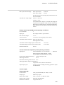
EQUIPMENT RATINGS
Supply voltage
85 to 264 Vac
Frequency
50/60 Hz
Power or current ratings
18 VA maximum
EQUIPMENT CONDITIONS
Do not operate the instrument in the presence of flammable liquids or vapors. Operation of any electrical
instrument in such an environment constitutes a safety hazard.
Temperature
0 to 50°C
Humidity
10 to 90% RH
Vibration
Frequency 10 to 60 Hz
Acceleration 2 m/s2 maximum
EQUIPMENT INSTALLATION
The controller must be mounted into a panel to limit operator access to the rear terminals.
i
Safety Precautions
This manual describes how to use this product. Before using this product, thoroughly read
and understand the descriptions in this manual to ensure correct use.
After you have read this manual, store the manual a safe place nearby so that it can be
referred whenever need.
WARNING
• Before connecting or disconnecting wiring to or from this product, be sure to
turn the mains power supply OFF. Inadvertently touching terminals or other
electrically live parts might cause electric shock.
• Before connecting this product to the measurement target or external control
circuits, make sure that it is connected to an earth. Failure to do so might
cause electric shock or fire.
CAUTION
• Wire this product properly in accordance with predetermined wiring standards, instruction described in this manual and generally accepted wiring methods. Failure to
do so might result in electric shock, fire or malfunction.
• Use this product only within the recommended operating conditions (temperature,
humidity, voltage, vibration, shock, atmosphere, etc.) described in the specifications.
• Do not cover the ventilation holes on this product. Doing so might result in fire or
malfunction.
• Do not disassemble this product, or touch parts inside. Doing so might result in electric shock or malfunction.
• Some parts in this product become hot while the power is turned ON or are hot
immediately after the power is turned OFF. Do not touch these parts. Doing so might
result in burns.
• Do not operate the operation keys on this product with the top of a propelling pencil or
other sharp-tipper object. Doing so might result in malfunction.
ii
Contents
Safety Precautions
Chapter 1
NAMES AND FUNCTIONS OF COMPONENT PARTS......................... 1-1
Chapter 2
INSTALLATION ...................................................................................... 2-1
2-1
2-2
2-3
2-4
2-5
2-6
Chapter 3
Setup Operation .................................................................................................................
Setup Table ........................................................................................................................
Basic Operation for Setup .................................................................................................
Description on the Setup Items .........................................................................................
4-1
4-2
4-3
4-5
SETTING OF PARAMETERS ................................................................ 5-1
5-1
5-2
5-3
5-4
5-5
5-6
Chapter 6
Cables ................................................................................................................................ 3-2
Terminal Connections ........................................................................................................ 3-3
Terminal Arrangement ....................................................................................................... 3-4
Power Supply Connections ............................................................................................... 3-4
Grounding .......................................................................................................................... 3-5
Input Connection ............................................................................................................... 3-5
Output Connection ............................................................................................................. 3-6
Connection of Remote Switch(option) ............................................................................... 3-7
Connection of Current Transformer (CT, option) .............................................................. 3-7
Communication Connection .............................................................................................. 3-8
Wiring Precautions ........................................................................................................... 3-10
Countermeasures Against Noise ..................................................................................... 3-10
SETTING THE SETUP ITEMS ............................................................... 4-1
4-1
4-2
4-3
4-4
Chapter 5
2-1
2-2
2-3
2-4
2-5
2-5
2-5
2-6
WIRING................................................................................................... 3-1
3-1
3-2
3-3
3-4
3-5
3-6
3-7
3-8
3-9
3-10
3-11
3-12
Chapter 4
SDC20 External Dimensions ..............................................................................................
SDC20 Panel Cutout Sizes ................................................................................................
SDC21 External Dimensions ..............................................................................................
SDC21 Panel Cutout Dimensions ......................................................................................
Mounting ............................................................................................................................
■ Location of mounting .....................................................................................................
■ Mounting method ..........................................................................................................
External Dimensions of Current Transformer ....................................................................
Parameters Table ...............................................................................................................
Basic Parameter Operation ...............................................................................................
Assigning a Parameter to the PARA Key ........................................................................
Resetting a Parameter Assigned to the PARA Key ........................................................
Operation of Parameters Assigned ...................................................................................
Description on Parameters ................................................................................................
5-1
5-2
5-3
5-4
5-5
5-6
OPERATION........................................................................................... 6-1
6-1
6-2
6-3
6-4
6-5
6-6
6-7
6-8
6-9
Turning on the Power Supply ............................................................................................ 6-2
Indicating a PV ................................................................................................................... 6-4
Indicating an SP ................................................................................................................. 6-4
Indicating the Output Value ............................................................................................... 6-5
Indicating the Heater Current Value (optional) ................................................................. 6-6
Changing an SP (with single SP) ....................................................................................... 6-7
Changing an SP (with multi SP) ......................................................................................... 6-8
Selecting the SP of Multi SP .............................................................................................. 6-9
Changing the Set Value of Event (optional) .................................................................... 6-10
iii
6-10
6-11
Chapter 7
TROUBLESHOOTING ........................................................................... 7-1
7-1
7-2
7-3
7-4
Chapter 8
Alarms Indication ...............................................................................................................
Alarm Codes Table ............................................................................................................
Heater Breakage Alarm .....................................................................................................
Other Troubles ...................................................................................................................
7-1
7-1
7-2
7-3
SPECIFICATIONS .................................................................................. 8-1
8-1
8-2
Chapter 9
Changing the Set Value of PV Bias ................................................................................. 6-11
Changing Various Parameters ........................................................................................ 6-12
Model Number Configuration ............................................................................................ 8-1
Specifications .................................................................................................................... 8-4
MAINTENANCE ..................................................................................... 9-1
APPENDICES
Setup Table ......................................................................................................................Appendix-2
Parameter Table ...............................................................................................................Appendix-4
Input Ranges Table ..........................................................................................................Appendix-5
Alarm Table ......................................................................................................................Appendix-6
SDC 20/21 Setting Work Sheets ......................................................................................Appendix-7
Description on Terms and Abbreviations ......................................................................Appendix-12
iv
Chapter 1
Chapter 1
NAMES AND FUNCTIONS OF COMPONENT PARTS
NAMES AND FUNCTIONS OF COMPONENT PARTS
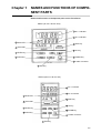
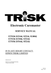
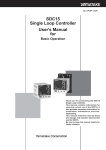
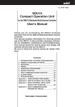
Names and Functions of Component parts on the Front Panel
SDC21 (96 mm x 96 mm size)
3
4
1
No. 1 indicator
2
No. 2 indicator
5
DISP key
9
UP key
10
DOWN key
11
Loader connector
Mode LED
Green belt
8
SP/EV key
7
PARA key
8
ENT key
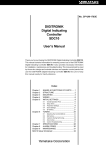
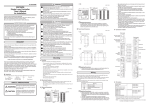
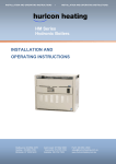
SDC20 (48 mm x 96 mm size)
3
4
8
7
1
No. 1 indicator
2
No. 2 indicator
5
DISP key
9
UP key
10
DOWN key
11
Loader connector
Mode LED
Green belt
SP/EV key
PARA key
8
ENT key
1-1
Chapter 1
NAMES AND FUNCTIONS OF COMPONENT PARTS
1
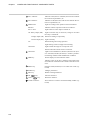
No.1 indicator:
Indicates a PV(Process Variable) and can also indicate
the contents of parameters, etc.
2
No.2 indicator:
Indicates an SP (Set Point) and can also indicate the numerics of parameters, etc.
3
Model LED:
Lights according to the operation of this instrument.
SP/OUT:
Indicates what is expressed in the No.2 indicator .
EV1 to EV3:
Lights when an event output is turned on.
OT: Relay output (OD).
Lights when the relay is turned on, and goes out when
the relay is turned off.
Voltage output (6D). Flashes according to output duty.
Current output (5G). Lights normally.
AT:
Flashes during auto tuning operation.
Lights during overshoot suppression learning.
Green belt:
Lights within the range set in setup item C23.
Flashes when the remote switch is turned on.
4
Green belt:
Lights when a difference (deviation) between PV (Process Variable) and SP (Set Point) is within a predetermined range. Flashes under the READY condition.
5
DISP key:
Set the display to basic indication status.
Indicates a PV on the No.1 indicator and an SP on the
No.2 indicator. Determines the contents of the No.2 indicator.
1-2
6
SP/EV key:
Changes an SP (Set Point) or a set value of an event (optional).
7
PARA key:
Changes parameters.
8
ENT key:
Defines a changed numeric.
9
UP
10
Down
11
Loader connector:
key:
key:
Increases numerics.
Decreases numerics.
This connector is used to connect the Handy Loader (optional).
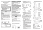
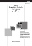
Unit: mm
Terminal screw M3.5
Terminal cover set (optional)
81446088-001
Chapter 2
Soft dust-proof cover (optional)
81446086-001
Mounting bracket
81405411-001
2-1
Hard dust-proof cover set (optional)
81446082-001
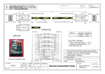
SDC20 (48 x 96)
Chapter 2
INSTALLATION
INSTALLATION
SDC20 External Dimensions
2-1
2-2
HANDLING PRECAUTIONS
• When gang-mounting, make sure that the controller is used
in an operating temperature of 40°C or below.
N: No. of mounting units
Unit: mm
Panel cutout size
52 min. (59 min. with the hard dust-proof cover)
Panel cutout size (Recommended) with
vertical and horizontal mounting
2-2
Panel cutout size for closed mounting
(Recommendable sizes)
SDC20 (48 x 96)
Chapter 2
INSTALLATION
SDC20 Panel Cutout Sizes
Soft dust-proof cover (optional)
81446087-001
Mounting bracket
81405411-001
Unit: mm
Terminal screw M3.5
Terminal cover set (optional)
81446084-001
2-3
Hard dust-proof cover set (optional)
81446083-001
SDC21 (96 x 96)
Chapter 2
INSTALLATION
SDC21 External Dimensions
2-3
2-4
HANDLING PRECAUTIONS
• When gang-mounting, make sure that the controller is used
in an operating temperature of 40°C or below.
N: No. of mounting units
Panel cutout size
Unit: mm
99 min. (107 min. with the hard dust-proof cover)
Panel cutout size (Recommended) with
vertical and horizontal mounting
2-4
Panel cutout size for closed mounting
(Recommended sizes)
SDC21 (96 x 96)
Chapter 2
INSTALLATION
SDC21 Panel Cutout Dimensions
Chapter 2
2-5
INSTALLATION
Mounting
■ Location of mounting
Mount the instrument at a location which satisfies the following conditions.
• Mount the instrument in locations:
or low humidity.
Not subject to high or low temperatures, or high
• Free of corrosive gas (sulfide gas, etc.)
• Free of dust particles, soot, or the like.
• Not exposed to direct sunlight or the weather.
• Free of mechanical vibrations.
• Do not mount instrument near a high-tension line, a welder, or electrical noise generating sources.
• Make sure the instrument is more than 15 meters from a boiler or other high-voltage
ignition devices.
• The location should not be subject to a strong magnetic field.
• The location should not be subject to inflammable liquids or gases.
■ Mounting method
• Mount the instrument so that it does not tilt horizontally more than 10° (+ or -).
• Use a steel panel with a plate thickness of more than 2 mm.
• Fix the upper and lower panels of the instrument securely by using the attached mounting bracket.
Panel
Front
Mounting method (SDC21)
2-5
Chapter 2
2-6
INSTALLATION
External Dimensions of Current Transformer
This current transformer is used to detect a heater breakage in a model provided with a
heater breakage alarm function at option. The current transformer is available by request.
CT (5.8 mm dia.) — QN206A
CT (12 mm dia.) — QN212A
12 mm dia.
2.36 mm dia.
5.8 mm dia.
3.5 x 2 mm dia.
2-6
Chapter 3
Chapter 3
WIRING
WIRING
• A switch in the main supply is required near the equipment.
• In case of AC power supply models, main power supply wiring requires a (T) 0.5 A,
250 V fuse(s). (IEC127)
• The following table shows the meaning of the symbols in the terminal wiring label on
the instrument top.
Symbol
~
Description
Alternating current
Direct current
Earth (ground) terminal
Caution, risk of electric shock
Caution
3-1
Chapter 3
3-1
WIRING
Cables
Connect thermocouple wires to the terminals in case of a thermocouple input. When a
thermocouple is connected to terminals, or wiring is extended, connect the wires via a
shielded compensating lead wire.
• For input/output other than thermocouples, use a shielded polyethylene insulated vinyl
shielded cable for instrumentation use conforming to JCS-364 or equivalent (generally
called twisted shielded cable for instrumentation use).
• A shielded multiconductor microphone cord (MVVS) may be used, if electromagnetic
induction noise are comparatively low.
Reference
Recommended twisted shielded cables
2 conductors
IPEV-S-0.9 mm2 x 1P
3 conductors
ITEV-S-0.9 mm2 x 1P
2 conductors
KPEV-S-0.9 mm2 x 1P
3 conductors
KTEV-S-0.9 mm2 x 1P
Fujikura Cable Co.
Hitachi Cable Co.
3-2
Chapter 3
3-2
WIRING
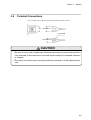
Terminal Connections
Use a crimped style solderless terminal compatible with M3.5 screw.
7.4
Less than 7.3
4.3 mm dia.
Less than 6.6
CAUTION
• Be sure to use round crimped style solderless terminals to prevent disconnection
from terminals, if the instrument is mounted at place subject to noticeable vibrations
or impacts.
• Be careful not to allow any crimp style solderless terminals to touch adjacent terminals.
3-3
Chapter 3
3-3
WIRING
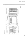
Terminal Arrangement
Terminal Arrangement (rear view)
SDC20 (48 x 96)
SDC21 (96 x 96)
1
10
1
20
10
2
11
2
21
11
3
12
3
22
12
4
13
4
23
13
5
14
5
24
14
6
15
6
25
15
7
16
7
26
16
8
17
8
27
17
9
18
9
28
18
29
19
19
3-4
Power Supply Connections
• Obtain the power source of SDC20/21 AC power supply models from a single-phase
instrumentation power source not subject excess noise.
• Obtain the power source of SDC20/21 24V dc power supply models from a 24V dc
±10% power source.
• If the power source generates noise, add an insulation transformer, and use a line filter.
Line filter Yamatake Corporation
Model No. 81446364-001
[AC Power supply models]
Instrument
power supply
200/200 V
100/100 V
Insulation
transformer
Recommended product
81446364-001
Line filter
3
1
85 to 264V ac
50/60 Hz
SDC20/21
1
2
E
4
2
3
Grounding
Grounding
Other circuits
[24V dc Power supply models]
Instrument
power supply
200/200 V
100/100 V
Insulation
transformer
Recommended product
81446364-001
24V dc ±10%
Line filter
1
AC
50/60 Hz
3
E
2
4
DC
Power
Supply
1
2
3
Grounding
Other circuits
SDC20/21
Other circuits
Grounding
Reducing electrical noise
Be careful not bundle the primary and secondary coils of the power cable together. Do
not put them into the same conduit or duct after introducing noise-reduction measures.
3-4
Chapter 3
3-5
WIRING
Grounding
Connect the instrument by one-point grounding to GND terminals (terminal 3 and
4 ). Do not perform any jumping wiring. Mounting a grounding terminal strip separately, and connect shielded cables, etc. to the ground, if grounding work is difficult.
Grounding type:
Lower than 100 Ω
Grounding conductor:
Annealed copper wire more than 2 mm2 (AWG14)
Grounding conductor length:
Max. 20 m
GND terminal
Shield GND
Grounding terminal board
Shield
3-6
Input Connection
Connect the thermocouple input, resistance thermometer input, voltage input, and current input as shown below.
Inside the instrument
Inside the instrument
Thermocouple input
Voltage input
Resistance
thermometer input
Current input
CAUTION
Be careful not to apply any voltage to current input terminals (6,8), otherwise the instrument may malfunction.
3-5
Chapter 3
3-7
WIRING
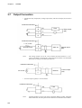
Output Connection
• Connect the relay output (0D), voltage output (6D), and current output (5G) as shown
below.
Inside the instrument
Load
Relay output
(0D)
Inside the instrument
1.1 kΩ ±10%
22.5V dc ±15%
Note:
SSR, etc.
Voltage output
(6D)
The voltage output is 22.5V dc ±15%, and the internal resistance is 1.1 kΩ
±10%. If an SSR is connected as a load, examine the number of connectable
SSR units according to the SSR specifications.
Inside the instrument
4 to 20 mA
Receiver
Current output
(5G)
• An event output (option) is sent as follows.
Inside the instrument
Load
Note:
3-6
Terminal numbers of the event output (optional) differ by model. Check the
label mounted on the side panel of this instrument to determine the numbers.
Chapter 3
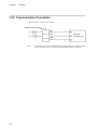
WIRING
• An auxiliary output (option) is sent as follows.
Inside the instrument
4 to 20 mA
3-8
Receiver
Note 1:
Terminal numbers of the auxiliary output (option) differ by model. Check the
label mounted on the side panel of the instrument, to determine the numbers.
Note 2:
Isolation is not executed between the auxiliary output (5G) and others, and
between the auxiliary output and voltage output (6D). Use an isolator as required. Refer to 8-2, “Specification input-output isolation”, on page 8-6.
Connection of Remote Switch(option)
Inside
the instrument
No-voltage contact
Note:
3-9
Use a non-voltage remote switch input and a micro current contact (contact
type).
Connection of Current Transformer (CT, option)
Inside the instrument
I 7 (I4)
I 8 (I5)
Note:
Connect a heater current conductor through the current transformer (once only).
3-7
Chapter 3
WIRING
3-10 Communication Connection
• The RS-232C is connected as follows.
Inside the instrument
RD
SD
Personal
computer, etc.
SG
Note:
3-8
Terminal numbers of SD and RD differ by model. Refer to the label mounted
on the side panel of this instrument for SD and RD number verification.
Chapter 3
•
WIRING
With RS-485
RS-485 mutual connection diagram
SDC (Slave station side)
Terminal numbers of SDA, SDB, RDA, and
RDB differ by model. Refer to the label
mounted on the side panel of this instrument
for verification.
Connect a terminating resistor in the master
station and the farthest slave station. Use a
resistor of 150 Ω, 1/2W or over.
Shield
Master station side
Do not assign the SDC20/SDC21 to the same
address as other instruments connected to the
same RS-485 communication line (excluding address 0).
Note: Be sure to connect SG terminals each
other. Failure to do so might cause
unstable communications.
Shield
Shield
SDC (Slave station side)
SDC (Slave station side)
CAUTION
Be careful not to short terminals across SDA and SDB or across RDA and RDB,
otherwise this instrument may malfunction.
3-9
Chapter 3
WIRING
3-11 Wiring Precautions
• Connect cables according to the instrument model number and terminal numbers on
the label mounted on the side panel of this instrument. After wiring, make sure the
wiring connections are correct.
• Separate input/output signal cables and communication cables more than 50 cm from a
drive power cable or a power cable higher than 100 V. Do not pass these cables together through the same conduit or duct.
• Be careful not to allow crimped style solderless terminals to touch any adjacent terminals.
3-12 Countermeasures Against Noise
The following noise generation sources are the most common.
1
Relay and contacts
2
Solenoid coils and solenoid valves
3
Power line (higher than 100V ac, in particular)
4
Inductive load
5
Motor commutator
6
Phase angle control SCR
7
Radio communication equipment
8
Welding machine
9
High-voltage ignition devices
The following methods are effective as countermeasures against noise.
1
A CR filter is effective for quick-rising noises such as impulse noise.
Recommended CR filter
Yamatake Corporation
2
Model No. 81446365-001
A variator is effective for noises with high crest values.
Be careful since the variator is shorted if it malfunctions.
Recommended variator
Yamatake Corporation
Model No. 81446366-001 (for 100 V)
81446367-001 (for 200 V)
3-10
Chapter 4
Chapter 4
SETTING THE SETUP ITEMS
SETTING THE SETUP ITEMS
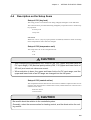
This chapter provides descriptions on the setup items required for the instrument built in
an equipment for the first time to be put in operating states.
It is necessary to set the operating conditions such as the input range and control action
according to how to use the equipment, before operating the instrument. This is called a
setup.
If the instrument has already been built in and its setup has been completed, this chapter
may be skipped.
4-1
Setup Operation
Before starting the setup, check the items and set values, which meet the equipment to be
used, in accordance with the setup items table. Determine the setup values in advance,
using the “Setting Work Sheets" attached at the end of this manual as an appendix.
To execute the setup, place this instrument in the basic indication states.
The basic indication states means such that the No.1 indicator shows a PV, and No.2
indicator shows an SR, OUT or a heater current value.
If the instrument is not in the basic indication states, press the DISP key.
There are 29 setup items from C01 to C39 (including missing numbers).
Among these items, set the necessary items only.
Some items may use the initial values as they are.
If there is no relevant item due to a special model, this Item No. is not indicated, but
skipped. Setup item C40 is used for factory adjustment.
After C40, C01 follows.
4-1
Chapter 4
4-2
SETTING THE SETUP ITEMS
Setup Table
Setup item
Indication
Action
Reference
page
Key lock
C
0
1
Sets whether or not key operation is enabled.
4-5
Temperature unit
C
0
2
Selects °C or °F.
4-5
Control action
C
0
3
Determines the direction of control action.
4-5
Type of PV input range
C
0
4
Determines the type and range of a PV input.
4-6
Decimal point position
C
0
5
Determines the decimal point position in PV, SP indication.
4-8
PV range low-limit
C
0
6
Determines the PV input range.
4-8
PV range high-limit
C
0
7
Determines the PV input range.
4-8
SP setting system
C
0
8
Sets either single SP or multi SP.
4-8
Lower-limit of SP
C
0
9
Determines an SP setting range.
4-9
Upper-limit or SP
C
1
0
Determines an SP setting range.
4-9
Selection of output in
case of PV abnormal
C
1
1
Selects the type of output when a PV input is abnormal.
4-9
Setting of output in case
of PV abnormal and when
READY mode
C
1
2
Determines the value of output when a PV input is abnormal
and when READY mode.
4-9
Time proportional cycle
C
1
3
Determines the cycle in units of second (in model 0D, 6D).
4-9
Initial manipulated
variable in PID operation
C
1
5
Determines the PID control output values when the power
supply is turned on or AT is finished.
4-9
PID operation initialize
C
1
6
Initializes the PID operation so that the output may not change
suddenly when an SP value is changed.
4-10
Control system selection
C
1
8
Selects the overshoot suppression function during control action.
4-10
Type of auxiliary output
C
2
1
Type of auxiliary output
4-12
Green belt
C
2
3
Determines the absolute value of PV-SP. The green belt lights
when this value is lower than a specified value.
4-12
Event 1 type
C
2
4
Determines the type of Event 1.
4-13
Event 2 type
C
2
5
Determines the type of Event 2.
4-13
Event 3 type
C
2
6
Determines the type of Event 3.
4-13
Remote switch function
C
2
7
Determines the function of the remote switch.
4-16
Communication address
C
3
1
Determines the communication address.
4-17
Transmission speed
C
3
2
Determines the communication speed.
4-17
Communication code
C
3
3
Determines the type of communication code.
4-17
SP ramp up gradient
C
3
5
Makes variation per unit time constant when an SP value is
changed.
4-17
SP ramp down gradient
C
3
6
Makes variation per unit time constant when an SP value is
changed.
4-17
Zener barrier adjustment
C
3
9
Corrects dispersion in Zener barrier resistance value.
4-18
4-2
Chapter 4
4-3
SETTING THE SETUP ITEMS
Basic Operation for Setup
In this instruction manual, the purpose of operation and the operation procedure are given
on the left side of page, and the result of operation and the states indicated on the instrument are given on the right side.
The basic operation for set up is as follows;
Operation Procedure
DISP
1
To set to basic
indication status
Press the
key.
A PV set value at that
time is indicated.
The set value of that
item is indicated.
SP
OUT
Note) This procedure is not required when the basic indication is already given.
2
To indicate the setup
item seconds.
Continuously, press the
ENT key and
keys
together for 3 seconds.
C
(Jump to step 6 in
otherwise case), press
the ENT key.
C
01
SP
OUT
3
4
5
6
To change the set value
To change the set value
To define the changed
numeric
To transfer to the next
setup item
Change the numeric,
using the
key or
key.
Press the ENT key.
→ Flashing stops and the
set value is defined.
After making sure that the
numeric does not flash,
press the
key.
7
To change the numeric
→ Repeat steps
3 → 4 → 5 → 6
Not to change the
numeric
key
→ Press the
to transfer to the next
setup.
To reset to basic
indication status.
Press the
The set value of that
item is indicated.
SP
OUT
01
The numeric flashes.
0
C
SP
OUT
01
1
C
SP
OUT
SP
OUT
Keeps flashing.
01
1
C
Note) To reset to the preceding setup item, press the
C01 is indicated.
02
Does not flash.
C02 is indicated in
this case.
0
key.
SP
OUT
A PV numeric is
indicated.
An SP numeric is
indicated.
DISP
8
key.
4-3
Chapter 4
SETTING THE SETUP ITEMS
One Point Memo
This is a convenient function to be memorized.
How to use the up
key or down
key.
To change the set values of the indicator, use these key.
When the
key is pressed once, the numeric is incremented by one. When the down key is pressed
once, the numeric is decremented by one.
When the up
key or down
key is pressed continuously, the numeric in the indicator is continuously incremented or decremented, and more over the changing speed is accelerated gradually.
When this function is used effectively, the set value can be changed greatly and conveniently.
An example is given below.
(Example)
To change the numeric from 500 to 1000.
500
At first
Press the
key continuously.
Release holding from the
a little before 1000.
Press the
continuously.
key
key again
Release holding from the
immediately before 1000.
key
Press the
key, for example,
three times, or for a while.
4-4
506
The numeric begins to increase.
972
The numeric stops a little
before 1000.
978
The numeric begins to increase.
997
The numeric stops immediately
before 1000.
1000
The numeric stops at 1000.
Chapter 4
4-4
SETTING THE SETUP ITEMS
Description on the Setup Items
Setup of C01 (key lock)
This setup prevents a set numeric from being changed, although it can be indicated.
The control action is prevented from being changed by an operation miss or unnecessary
key operation.
0: No key lock
1: Key lock
Check item
When C01 is set to 1, any key input operation is inhibited, and the set values of all setup
items and parameter items cannot be changed.
Setup of C02 (temperature unit)
This setup selects °C or °F as temperature unit.
0: °C
1: °F
CAUTION
• After changing the temperature unit, check if C06, C07 (upper and lower limits of
PV input range), C05 (decimal point position),C09, C10 (upper and lower limits of
SP limit) and event set values are correct.
• When selection is done, the upper and lower limits of a PV input range, and the
upper and lower limits of an SP range are changed into the full spans.
Setup of C03 (control action)
This setup determines the directions of control action. When the output increases as a PV
increases, the control action is called a direct action, and the otherwise control action is
called a reverse action.
0: Reverse action
1: Direct action
CAUTION
Be careful about the relation to the controlled system.
Generally, select the reverse action for heating control, and the direct action for cooling control.
4-5
Chapter 4
SETTING THE SETUP ITEMS
Setup of C04 (type of PV input range)
This setup determines the type of a PV input and the reference temperature range.
Set a desired number in accordance with the input ranges table.
CAUTION
After changing the input range, check if the upper and lower limits of a PV input range,
decimal point position, the upper and lower limits of an SP limit, and event set values
are correct.
4-6
Chapter 4
SETTING THE SETUP ITEMS
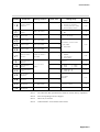
Input Ranges Table
°C range
°F range
0 to 1200
0 to 2200
0.0 to 800.0
0 to 1400
03
-200.0 to +400.0*
-300 to +700
04
0 to 1200
0 to 2000
0.0 to 800.0
0 to 1400
-200.0 to +400.0*
-300 to +700
No.
Type
01
02
05
K
J
06
07
E
0.0 to 800.0
0 to 1400
08
T
-200.0 to +400.0*
-300 to +700
09
R
0 to 1600
0 to 3000
10
S
0 to 1600
0 to 3000
11
B
0 to 1800
0 to 3200
12
N
0 to 1300
32 to 2372
13
PLII
0 to 1300
32 to 2372
14
Wre5-26
0 to 2300
0 to 4000
16
Ni-Mo
0 to 1300
32 to 2372
17
DIN U
-200.0 to +400.0*
-300 to +700
18
DIN L
0.0 to 800.0
0 to 1400
20
JIS
-200.0 to +500.0*
-300 to +900
21
Pt 100
-100.0 to +200.0
-150.0 to +400.0
30
JIS
-200.0 to +500.0*
-300 to +900
31
Jpt 100
-100.0 to +200.0
-150.0 to +400.0
40
4 to 20 mA
41
0 to 20 mA
45
1 to 5 V
46
0 to 5 V
50
0 to 10 mV
51
0 to 100 mV
52
-10 to +10 mV
Note:
Scaling and decimal point position are
variable within a range of -1999 to +9999.
Although -200.0 cannot be indicated, the action is normal.
In the ranges with decimal point indication, indication can be performed to
one decimal point.
4-7
Chapter 4
SETTING THE SETUP ITEMS
Setup of C05 (decimal point position)
This setup determines whether a decimal point is added to the PV indication and SP
indication. With the temperature input, the range shown with a decimal point in the input
ranges table can be set to one decimal digit.
A decimal point can be added to any position with a linear input.
0: With no decimal point
1: One decimal digit is indicated.
2: Two decimal digits are indicated.
3: Three decimal digits are indicated.
Check items
• This setup is disabled, depending upon the contents of setup of C04.
• When changing the decimal point position, check if the upper and lower limits of the
input range, the SP set value, the upper and lower limits of the SP limit, event set
values, event hysteresis, and SP ramp are correct.
Setup of C06 (lower limit of PV input range)
Setup of C07 (upper limit of PV input range)
With the temperature input, the PV input range can be narrowed.
For example, the reference temperature range of 0.0 to 800.0°C can be narrowed to 0.5 to
500.0°C in No.02 (input type K) of the input ranges table. In such a case, set the lower
limit to 0°C, and the upper limit to 500°C.
With the linear input, desired numerics can be assigned to 0% and 100%.
For example, 4 mA can be assigned to 0 and 20 mA to 1000 in case of 4 to 20 mA input.
In this case set the lower limit to 0 and the upper limit to 1000.
Check items
• With the temperature input, the input range can be setup to:
“Upper limit value — Lower limit value ≥ Reference temperature range/4 "
• When changing the upper and lower limits of the PV input range, check if the upper
and lower limits of the SP limit, and event set values are correct.
• When the upper and lower limits of the PV input range have been changed, the PID
constants are determined, depending upon the range changed.
• After the upper and lower limits of the SP limit are set earlier via C09 and C10, the
upper and lower limits of range can be set to a narrower range, but SP is determined,
depending upon the value determined as the SP limit. In such a case, set the SP limit
again.
Setup of C08 (SP setting system)
This setup selects either single SP or multi SP.
0: Single SP
1: Multi SP
4-8
Chapter 4
SETTING THE SETUP ITEMS
Setup of C09 (lower limit of SP limit)
Setup of C10 (upper limit of SP limit)
This setup restricts the setup and indication of SP.
CAUTION
• Set C06 and C07 after setting C09 and C10.
• This setup cannot be done out of the range of C06 and C07. However, when C09
and C10 are set earlier, C06 and C07 may be set to values smaller than the limit
values.
Setup of C11 (selection of output in case of PV over-range)
This setup is provided to set an output when a PV input has become abnormal.
0: Normal PID operation values are output in over-range.
1: Values set via C12 in output in over-range.
Setup of C12 (output in case of PV over-range)
This setup is provided to set an output value when a PV input has become abnormal and
when READY mode.
The unit is %. Set an output value to the safety side of equipment, for example, in the
non-heating direction with a heater.
CAUTION
The abnormal PV input means an output of alarm AL01, AL02, AL03 or AL70.
Setup of C13 (time proportional cycle)
This setup determines the output cycle in the time proportional control in model 0D, 6D.
The unit is second.
CAUTION
The item is skipped in model 5G.
Setup of C15 (initial manipulated variable in PID operations)
This setup determines the PID control output values (manipulated variables)
when the power supply is turned on or the auto tuning is finished. There initial values can
be used as MV values.
4-9
Chapter 4
SETTING THE SETUP ITEMS
Setup of C16 (PID operation initialize)
This setup initializes the PID operations to prevent abrupt changes of outputs when an SP
value has been changed.
0: initializes automatically by the decision of this instrument itself (AUT).
1: Initializes each time an SP value changes (initializes at time of SP change).
2: Not initialized (continues PID).
Setup of C18 (control system selection)
This setup selects the function of suppressing overshoot during control action.
0: Normal PID.
1: Overshoot relaxation:
A certain overshoot suppression effect is obtainable.
However, the suppression strength is fixed.
2: Learning function condition:
Optimum suppression strength is learnt according to a control system.
3: Fixed learning condition:
The optimum suppression strength obtained by
learning is fixed.
In the initial control action, operate the instrument with C=0, and check overshoot states.
When there is an overshoot, set C18 to 1 and check if the overshoot is of a satisfactory
value during control action.
When satisfactory, this learning is terminated as it is.
If not, set C18 to 2, and execute learning by repetitive control.
Repeat the learning until the satisfactory results are obtained. When the results of learning are satisfactory, set C18 to 3, and fix the results of learning to terminate the learning.
4-10
Chapter 4
Set PID constants by
AT or manually.
SETTING THE SETUP ITEMS
Check whether there
is no hunting in usual
PID control.
Control with C18 = 1.
When unsatisfactory, execute
learning control
with C18 = 2.
If hunting is found or
control action is abnormal, make readjustment.
Control action by fixing
the overshoot suppression strength with C18 = 3.
After the overshoot level
becomes a satisfactory
value, terminate learning.
When there is hunting,
make readjustment.
Control action while
executing learning.
Learning Control Application Concept Diagram
4-11
Chapter 4
SETTING THE SETUP ITEMS
CAUTION
• Before selecting the overshoot suppression function, execute the auto tuning and
set optimum PID constants.
• If there is hunting in the control action, the overshoot suppression function is not
activated satisfactory.
In such a case, reset the PID constant.
• When SP is changed with C18=2, the suppression strength is rewritten as soon as
learning is terminated.
• If any of the following items occures during learning, the learning is interrupted.
1
When SP is changed.
2
When auto tuning is executed.
3
When the SP ramp is executed.
4
When an alarm occures.
Setup of C21 (type of auxiliary output) (optional)
The auxiliary output is sent as a 4 to 20 mA dc current signal.
The contents can be selected by PV, SP or MV (manipulated variable).
0: PV
1: SP
2: MV (manipulated variable)
Zero and span outputs are as specified below.
Type output
Zero (4 mA)
Span (20 mA)
SP
Lower-limit value of SP (C9)
PV
Lower-limit value of PV range (C6) Upper-limit value of PV range (C7)
Manipulated
0% (Fixed value)
variable
Upper-limit value of SP (C10)
100% (Fixed value)
A PV output value or a manipulated variable output value ranges from -10% (2.4 mA) to
+110% (21.6 mA).
Setup of C23 (green belt)
This setup indicates that a control value is within a specified range.
The green belt lights when the absolute value of the control deviation (PV-SP)becomes
lower than a specified value.
This setup is used to set a control deviation value when the green belt lights.
4-12
Chapter 4
SETTING THE SETUP ITEMS
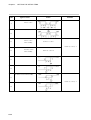
Setup of C24, C25 and C26 (event types) (optional)
If the event output relay is added (optional), a maximum of 3 points can be set, depending on the model. The operating conditions can be set independently for each output.
The types and functions of events are shown below. “EV” shows an event set value,
while “F” shows a hysteresis set value.
Set the event 1 in C24, the event 2 in C25, and the event 3 in C26.
For the event type setting, use the event codes shown in the following event codes table.
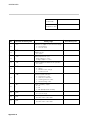
Event Codes Table
Code
Types of event
Deviation
Direct action
Deviation
Reverse action
Deviation
Direct action
with standby
Deviation
Reverse action
with standby
PV
Direct action
PV
Reverse action
PV
Direct action
Action
Remarks
1
2
3
Event on the condition that
the event output function is
turned on when the power
supply is turned on, the
event output function is kept
off in standby status unless
the condition for event
output off is satisfied once.
4
5
6
with standby
7
* Same as code 3, 4
PV
8
Reverse action
with standby
4-13
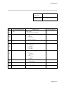
Chapter 4
Code
9
SETTING THE SETUP ITEMS
Types of event
Action
Remarks
Absolute value deviation
Direct action
Reverse action
10
Absolute value deviation
Direct action
11
with standby
Same as code 9
* Same as code 3, 4
Absolute value deviation
Reverse action
12
with standby
Same as code 10
SP Direct action
13
SP Reverse action
14
SP Direct action with standby
15
* Same as code 3, 4
SP Reverse action with standby
16
4-14
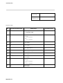
Chapter 4
Code
Types of event
Action
Alarm
ON during alarm occurrence
17
Timer
18
Remote switch
SETTING THE SETUP ITEMS
Remarks
This is output when an
alarm occurs.
There are none of setting
range and hysteresis.
There is no hysteresis.
Used in combination with
remote switch.
Only one point of timer
event can be assigned.
Heater breakage
19
0
Event OFF
4-15
Chapter 4
SETTING THE SETUP ITEMS
1
The event set value range by the SP/EV key is as shown below.
Event
Setting range
Deviation
±PV range span / 2 (more than -1999 unit)
PV
Within PV range
Absolute value deviation
0 to PV range span / 2
SP
Within SP limit range
Timer
1 to 9999 sec.
Heater breakage
0.0 to 50.0 A
CAUTION
• The initial values of C24 to C26 are 0 (event off) even in a model with the event
function.
Unless the type of the event is set, Hys1 to Hys3 are not indicated even when
parameters are set.
EV1 to EV3 cannot also be set by the
SP/EV
key.
• The heater breakage event is provided, it can be used not only as a heater breakage event but also as other events.
• The heater breakage event can be assigned to multiple events.
In this case, different set values are allowable.
(Example) E1 = 30 A, E2 = 20 A, E3 = 10 A
Setup of C27 (remote switch function)
If the remote switch (optional) is provided, one of the following action can be selected.
0: Non operation
1: READY/RUN selection
When the remote switch is turned off, this instrument executes normal control
action.
When the remote switch is turned on, the instrument is set to ready states, and
the control action stops. A set value of C is then sent as a control output. The
green belt flashes under ready states.
2: SP selection
With the multi SP, either SP0 or SP1 can be selected via the remote switch.
SP0 is selected when the remote switch is turned off, and SP1 is selected when
it is turned on.
In this case, no SP can be selected via keying operations.
4-16
Chapter 4
SETTING THE SETUP ITEMS
3: Timer event drive
The timer event is started and reset by the remote switch.
By turning on the remote switch, the timer event is started to turn on the event
output after a preset time.
By turning off the remote switch, the timer is reset to turn off the event output.
Check items
• The remote switch must held for 400 ms or more after it is turned on.
• The timer is reset by turning off the remote switch during timer operation.
The remote switch must be kept turned on until the event is output.
Setup of C31 (communication address)
This setup is used when the communication function is provided as option. Set the communication address from 0 to 127.
Setup of C32 (transmission speed)
This setup is used when the communication function is provided at option.
0: 9600bps
1: 4800 bps
2: 2400 bps
3: 1200 bps
Setup of C33 (communication code)
This setup is used when the communication function is provided at option.
0: 8 bits, even parity, and 1 stop bit
1: 8 bits, even parity, and 2 stop bits
Setup of C35 (SP ramp up gradient)
Setup of C36 (SP ramp down gradient)
The SP ramp function makes the set point changing rate per unit time constant when
changing an SP value.
It prevents the control output from changing suddenly due to a sudden change in SP.
The function also functions when the SP selection is changed in multi SP. The unit shown
is in unit/min.
Check items
• If the gradient is set to 0, the SP ramp does not function, and the SP is set to the point
just after the change.
• When the instrument power supply is turned on, the PV value is regarded as the start
point of the SP ramp after about 2.5 seconds.
4-17
Chapter 4
SETTING THE SETUP ITEMS
• When the READY condition has been changed to the RUN condition via the remote
switch, the PV value at that time is regarded as the start point of the SP ramp.
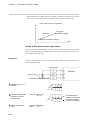
Action of SP ramp (in up gradient)
SP
Stop point
(SP after change)
Gradient
Start point (SP before change)
Time
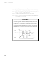
Set up of C39 (zener barrier adjustment)
This instrument must be adjusted to correct a dispersion of the resistance value of Zener
barriers with models having an additional Zener barrier processing function with a resistance thermometer bulb input.
Preparation
Connect a Zener barrier into A, B, C lines respectively, and short both ends of the resistance thermometer bulb.
Zener barrier
SDC20/21
Short circuit
Resistance thermometer bulb
1
Indicate C39 in No.1
indicator.
C
39
SP
OUT
2
3
Indicate the differential
resistance of Zener
barriers (A-B).
Press the
Define the adjusted
value.
Press the
again.
4-18
ENT
key.
SP
OUT
ENT
key
The differential resistance is indicated.
The present adjusted value is indicated.
Chapter 4
Note 1:
SETTING THE SETUP ITEMS
Use a Zener barrier having a resistance of 70 Ω or less.
The resistance difference between the Zener diodes connected to A and B
lines should be less than 20 Ω, otherwise no adjustment is possible.
Note 2:
This adjustment is not necessary if the instrument is used with an input other
than a resistance thermometer bulb input.
Note 3:
If no Zener barrier is used, this adjustment is not necessary even if the instrument is used with resistance thermometer bulb input.
CAUTION
When Zener barrier adjustment is performed once, the instrument cannot be used
with a resistance thermometer bulb input lacking Zener barrier. In such a case, the
above adjustment must be done without Zener barriers.
4-19
Chapter 4
SETTING THE SETUP ITEMS
This page left intentionally blank
4-20
Chapter 5
Chapter 5
5-1
SETTING OF PARAMETERS
SETTING OF PARAMETERS
Parameters Table
The following parametes are provided.
Parameters Table
No.
Item
1
Auto tuning start/stop
Indication
Setting condition Initial value
Setting range
Remarks
0: Execution stops
At
—
0
1: Execution starts
0.0 to 999.9%
2
Proportional band
P
—
5.0
0.1 to 999.9%
3
Integral time
I
P≠0
120
0 to 3600 sec.
4
Derivative time
D
P≠0
30
0 to 1200 sec.
5
Lower-limit of
manipulated variable
OL
P≠0
0
6
Upper-limit of
manipulated variable
Oh
P≠0
100
Manual reset
RE
I=0&P≠0
Differential
DI FF
P=0
PID1
A number is
added to the
above number.
C8 = 1
With Multi SP
Set point 0
SP
0
Set point 1
SP
1
EV1 hysteresis
HYS1
Option
EV1 is provided
7
8
9
10
50
5
C8 = 1
With Multi SP
11
EV2 hysteresis
HYS2
Option
EV2 is provided
12
EV3 hysteresis
HYS3
Option
EV3 is provided
13
PV bias
PB1A
—
Same as
specified
above.
Applied to models
0D and 6D.
Applied to model
5G.
0 to upper-limit %
Lower-limit to 100%
0 to 100%
1 to 100 unit
Same as specified
above.
0
Depends upon SP
limits (C9, C10).
5
0 to 100 unit
0
±1000 unit
Note 1:
In 8 PID, 2 to 7 are repeated by adding this number.
(P1, I1, d1.oL1, oH1, rE1/diFF1)
Note 2:
After
Note 3:
If an item is not set or it has no function, it is not indicated.
13
,
1
Can not be set in
alarm event or
timer event
modes.
follows.
5-1
Chapter 5
5-2
SETTING OF PARAMETERS
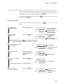
Basic Parameter Operation
The basic operation methods for parameters and examples of their execution are shown
below.
Operation Procedure
The procedure for setting the execution start of auto tuning is shown below.
DISP
1
To set to basic
indication status
Press the
key.
A PV value at this
time is indicated.
An SP value, OUT or
a heater current
value is indicated.
SP
OUT
2
3
4
To indicate parameters
Continue pressing the
ENT key and
keys
simultaneously for 3
SP
OUT
seconds.
To change the set
value (jump to step 6
when not to be chaged)
Press the
To change the set value
Use the
key.
key.
ENT
AT
To define the changed
numeric
SP
OUT
Press the
key or
ENT
6
To indicate the next
parameter.
A set value of that
item is indicated.
0
The numeric flashes.
1
Remains flashed.
1
Does not flash.
AT
key.
➪ Flashing stops and the set value is defined.
0
AT
SP
OUT
5
At is indicated.
AT
SP
OUT
After making sure that the
numeric does not flash,
press the
key.
SP
OUT
P
5.5
P is indicated at this
time.
Note) To reset to the preceding parameter,
press the
key.
7
To change the numeric
➪ Repeat steps 3 → 4 →
5
→
6
✎
SP
OUT
Not to change the numeric
➪ Press the
key to transfer
to the next parameter.
DISP
8
5-2
To reset to basic
indication status.
Press the
key.
A PV numeric is
indicated.
An SP numeric is
indicated.
Chapter 5
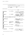
5-3
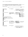
Assigning a Parameter to the
PARA
SETTING OF PARAMETERS
Key
This instrument can assign parameters, which are often used during operation, to the
PARA key, and call them as required, using the PARA key only.
A maximum of eight parameters can be assign to the
PARA
key.
Operation Procedure
The procedure for assigning the auto tuning (At) to the
PARA
key is shown below.
DISP
1
To set to basic
indication status
Press the
key.
A PV value at this
time is indicated.
An SP value, OUT or
a heater current
value is indicated.
SP
OUT
2
To indicate parameters
Continue pressing the
ENT key and
keys
simultaneously for 3
SP
OUT
seconds.
3
To indicate a parameter
to be assigned.
Press the
key.
At this time, At is
indicated in the status of
step 2 .
4
To assign the parameter
Press the
key, while
pressing the PARA key.
Four decimal points are
SP
OUT
indicated below the
parameter in No.1 indicator.
5
6
To transfer to the next
parameter to be
assigned
Press the
Repeat step
To reset to basic
indication status
Press the
AT
At is indicated.
0
A.T.. .
0
A set value of that
item is indicated.
Example of indication
in case the auto
tuning (At) is
assigned.
key.
4
.
key.
SP
OUT
A PV numeric is
indicated.
An SP numeric is
indicated.
CAUTION
If 9 or more parameters are attempted to be assigned, the parameter(s) assigned at
first is reset, and the new parameter(s) is assigned.
5-3
Chapter 5
5-4
SETTING OF PARAMETERS
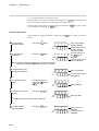
Resetting a Parameter Assigned to the
PARA
Key
Operation Procedure
The procedure for resetting the auto tuning (At) assigned to the
below.
PARA
key is shown
DISP
1
To set to basic
indication status
Press the
key.
A PV value at this
time is indicated.
An SP value, OUT or
a heater current
value is indicated.
SP
OUT
2
To indicate parameters
Continue pressing the
ENT key and
keys
simultaneously for 3
SP
OUT
seconds.
3
To indicate a parameter to be reset
Press the
key until the parameter is
indicated.
In this example, At is indicated in the status of
step 2 .
4
To reset the parameter
assigned.
Press the
key,
while pressing the PARA
key.
The decimal points in
No.1 indicator go out.
A.T.. .
0
At is indicated.
Four decimal points
light below the
parameter assigned
to the PARA key.
The set value of that
item is indicated.
AT
SP
OUT
The decimal points
indicated go out.
0
DISP
5
To reset to basic
indication status.
Press the
key.
SP
OUT
5-4
A PV numeric is
indicated.
An SP numeric is
indicated.
Chapter 5
5-5
SETTING OF PARAMETERS
Operation of Parameters Assigned
The set values of parameters assigned to the
one touch operation.
PARA
key can be checked or changed by
Operation Procedure
The procedure for changing the SP1 assigned to the
shown below.
PARA
key from 100°C to 200°C is
DISP
1
To set to basic
indication status
Press the
key.
A PV value at this
time is indicated.
An SP value, OUT or
a heater current
value is indicated.
SP
OUT
2
To indicate parameters
Press the
PARA
key.
SP
SP
OUT
1
100
The type of parameter
is indicated (SP1 is
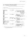
indicated in this
example).
The set value of that
item flashes (100 is
indicated in this
example).
3
4
5
To change the set
value
(jump to step 5 when
not to be chaged)
Change the numeric,
using the
key or
key.
To define the changed
numeric
➪ Flashing stops and the
set value is defined.
Press the
To transfer to the next
parameter.
Press the
ENT
SP
SP
OUT
key.
200
SP
SP
OUT
PARA
key.
To change the numeric
➪ Repeat steps 3 → 4 →
Remains flashed
(200 is indicated in
this example).
1
300
Does not flash.
The next parameter
is indicated.
SP
OUT
6
2
The set value of that
item flashes.
5
To keep the numeric unchanged
➪ Press the PARA key to tranfer
to the next parameter.
DISP
7
To reset to the basic
indication status.
Press the
key.
SP
OUT
A PV numeric is
indicated.
An SP numeric is
indicated.
Note) The parameters are indicated in the order of assignment.
5-5
Chapter 5
5-6
SETTING OF PARAMETERS
Description on Parameters
PID constants
When multi SP is selected in the setup item C08 (SP setting system), two groups of PID
constants are prepared.
P, I, D correspond to SP0, while P1, I1, D1 correspond to SP1.
Determine P=Proportional band, I=Integral time and D=Derivative time.
When setting I to 0, the integral action turns off so that the manual reset can be set.
When setting P to 0, the on-off action is selected, and the differential can be set.
However, P=0 cannot be set in model 5G (current output)
Check items
• When setting P to other than 0, the differential cannot be set.
• When setting I to other than 0, the manual reset cannot be set.
Upper and lower limits of manipulated variable (oH, oL)
These parameters oH and oL determine the upper and lower limits of the manipulated
variable.
They also serve as the upper and lower limits of the integral limiter.
Check items
The setting ranges of oL and oH are 0 to oH and oL to 100, respectively.
Manual reset (rE)
This is used for manually obtaining a control deviation when the integral is turned off.
This can be done when I=0 and P≠0.
Differential (dIFF)
This parameters can set a difference between the on point and the off point (differential,
dead band) in on-off action.
When P=0, the on-off action is then ready to set the differential. However, P=0 cannot be
set in 5G (current output).
5-6
Differential
Differential
Reverse action
Direct action
Chapter 5
SETTING OF PARAMETERS
Set point (SP0, SP1)
When multi SP is selected in the setup item C08 (SP setting system), two groups of SP
are prepared.
Event hysteresis (HYS1 to HYS3)
This parameter can set a difference between the event on and off points. (hysteresis dead
band)
However, this parameter cannot be set, in principle, in alarm event and timer event.
PV bias (PbIA)
The unit set to the PV bias is added to or subtracted from a PV value.
5-7
Chapter 5
SETTING OF PARAMETERS
This page left intentionally blank
5-8
Chapter 6
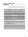
Chapter 6
OPERATION
OPERATION
Index to Work Contents
How to use this chapter:
This chapter provides descriptions on the operational procedures to be followed concerning the check or change items often required during a run. The index to the contents of
these check and change works and the pages on which the relevant descriptions are given
below.
Contents of Work
Reference pages
To indicate a PV
p.6-4
6-2. Indicating a PV
To indicate an SP
p.6-4
6-3. Indicating an SP
To indicate the output value
p.6-5
6-4. Indicating the Output Vlaue
To indicate the heater current value
p.6-6
6-5. Indicating the Heater Current Value
To change an SP (with single SP)
p.6-7
6-6. Changing an SP (with single SP)
To change an SP (with multi SP)
p.6-8
6-7. Changing an SP (with multi SP)
To select an SP (multi SP)
p.6-9
6-8. Selecting the SP of Multi SP
To change the set value of event (option)
p.6-10
6-9. Changing the Set Value of Event
To change the set value of PV bias
p.6-11
6-10. Changing the Set Value of PV Bias
To change various parameters
p.6-12
6-11. Changing Various Parameters
(1) To start the auto tuning assigned to the
PARA key
p.6-12
(2) To stop the auto tuning
p.6-15
(3) To change PID (proportional band, integral
time, derivative time) values
p.6-16
(4) To change oL and oH (lower and upper limits
of manipulated variable) value
p.6-17
(5) To change the rE (manual reset) value
p.6-18
(6) To change the dIFF (differential) value
p.6-19
(7) To change the HYS (event hysteresis) value
p.6-20
To indicate parameters as soon as possible
p.5-3
5-3. Assigning Parameters to the
key
PARA
6-1
Chapter 6
6-1
OPERATION
Turning on the Power Supply
This instrument is set to operating condition by turning on the power supply.
However, the instrument must be warmed up to satisfy the specified accuracy.
The warm up period ends after one hour or more.
The No.1 indicator does not indicate any PV for 2 to 3 seconds after turning on the power
supply.
During this period, the control output becomes 0%,and no event output is sent.
Caution in selecting READY/RUN by remote switch
The control action is controlled by an optional remote switch, when the remote switch is
assigned to the READY/RUN selection in the setup item C27.
Remote switch
ON:
READY status (control action stop).The green belt flashes.
OFF: RUN status
Note:
6-2
The control output in READY status is the value set in the setup item C12
“setting of output in case of PV over-range".
Chapter 6
OPERATION
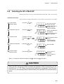
Auto tuning
Power ON
Basic indication status
DISP
DISP
DISP
SP / event setting
SP value setting
SP/EV
SP/EV
SP/EV
EV1 setting
DISP
SP/EV
EV2 setting
EV3 setting
SP/EV
SP selection
Assigned parameters setting
PARA
PARA
PARA
PARA1
PARA2
PARA
PARA3
PARA8
PARA
ENT
+
ENT
+
Parameters
Setup items
Described in Chapter 5.
Described in Chapter 4.
Optimum PID constants can be obtained by operating the auto tuning during a run. For
the auto tuning, see page 6-12.
This instrument is transferred from the basic indication states to various kinds of setting
states.
When the power supply is turned on, the instrument is set to the basic indication states.
The basic indication states in also restored by pressing the
DISP
key.
6-3
Chapter 6
6-2
OPERATION
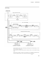
Indicating a PV
The control value of temperature or pressure applied to this instrument is called a PV
(Process Value).
When the instrument power supply is turned on, a PV is indicated in the No.1 indicator.
This status is called a basic indication status.
The contents of indication may be changed after operating any key.
DISP
To indicate a PV, press the
key, and a PV will be indicated in the No.1 indicator.
Operation Procedure
DISP
To indicate a PV
Press the
key.
A PV value at that
time is indicated.
SP
OUT
Note) If an alarm occurs, the alarm code and PV
value are indicated alternately.
6-3
Indicating an SP
A desired value for controlling a PV is called an SP (Set Point).
When the instrument power supply is turned on, a PV is indicated in the No.1 indicator,
and an SP in the No.2 indicator.
The contents of indication may be changed after pressing any key.
To indicate an SP, press the
DISP
key.
the SP LED lights and an SP is indicated in the No.2 indicator.
Operation Procedure
DISP
To indicate an SP
Press the
key.
A PV value at that
time is indicated.
An SP numeric is
indicated.
SP
OUT
DISP
Note) Press the
SP LED lights.
6-4
key several times until the
The SP LED lights.
Chapter 6
6-4
OPERATION
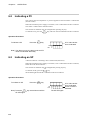
Indicating the Output Value
The output value for control can be indicated. The indicating method for the output value
and an example of its operation procedure are shown below.
Operation Procedure
When PV=600°C, SP=250°C and OUT=50.0% as an example, the indication procedure
is shown below.
DISP
1
To set to basic
indication status
Press the
key.
600
SP
OUT
250
A PV value at that time
is indicated.
The set value of SP is
indicated.
The SP LED lights.
DISP
2
To indicate the output
value
Press the
key.
600
SP
OUT
Note) With ON-OFF control,
OFF
or
ON
5 0.0
The output value is
indicated (unit is %).
The OUT LED lights.
is indicated as the output value.
DISP
3
To reset to basic
indication status
Press the
key.
SP
OUT
250
A PV value is
indicated.
The SP LED lights
again.
DISP
Note) When the heater breakage alarm function is provided, press the
key twice.
6-5
Chapter 6
6-5
OPERATION
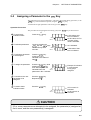
Indicating the Heater Current Value (optional)
To indicate the heater current value applied via a current transformer (CT) in a model
provided with the heater breakage alarm function, follow the operation procedure given
below.
Operation Procedure
In this example, PV=600°C, SP=250°C and the heater current value=28.0 A are assumed.
DISP
1
To set to basic
indication status
Press the
key.
600
SP
OUT
2
To indicate the heater
current value
When no heater current
value is indicated in step
600
DISP
1
, press the
key.
250
A PV value at that
time is indicated.
An SP value, OUT or
a heater current value
is indicated.
An SP value is
indicated in this
example.
SP
OUT
2 8.0
The heater current is
indicated.
Both SP and OUT
LED's go out.
DISP
3
To reset to basic
indication status
Press the
key.
600
SP
OUT
A PV numeric is
indicated.
250
Note) The unit is A (ampere).
When the control output is off, the heater current value cannot be measured.
Therefore, the last measured value in the control output on status flashes.
6-6
Chapter 6
6-6
OPERATION
Changing an SP (with single SP)
To change an SP value of single SP, follow the operation procedure given below.
Operation Procedure
The procedure for changing the SP from 500°C to 1000°C is shown below.
DISP
1
To set to basic
indication status
Press the
key.
A PV value at that
time is indicated.
A PV value at that
time is indicated.
An SP value, OUT or
a heater current
value is indicated.
SP
OUT
2
To indicate an SP
Press the
SP/EV
key.
5P
SP
OUT
3
4
To change the set
value
Change the numeric,
using the
or
key.
To define the changed
numeric
➪ Flashing stops and the
set value is defined.
Press the
To reset to basic
indication status
Press the
ENT
500
SP is indicated.
The set value of that
item flashes.
SP
SP
OUT
key.
1000
The changed numeric
flashes.
5P
SP
OUT
1000
Does not flash.
DISP
5
key.
SP
OUT
A PV numeric is
indicated.
An SP numeric is
indicated.
Note) With multi SP (C08 = 1), SP0 is indicated in the No.1 indicator, and its 0 flashes.
In this case, SP selection is done.
6-7
Chapter 6
6-7
OPERATION
Changing an SP (with multi SP)
To change an SP value of multi SP, follow the operation procedure given below. With
multi SP, there are two set values SP0 and SP1.
Operation Procedure
In this example, SP0 and SP1 have been assigned to the
changing the SP0 from 250°C to 300°C is shown below.
PARA
key. The procedure for
DISP
1
To set to basic
indication status
Press the
key.
A PV value at that
time is indicated.
An SP value, OUT or
a heater current
value is indicated.
SP
OUT
2
To indicate an SP
Press the SP/EV key.
several times.
5P
SP
OUT
3
4
To change the set
value
To define the changed
numeric
Change the numeric,
using the
or
key.
Press the
ENT
250
SP
SP
OUT
key.
SP0 is indicated.
The set value of that
time flashes.
0
300
5P
SP
OUT
0
The changed numeric
flashes.
0
300
Does not flash.
DISP
5
To reset to basic
indication status
Press the
key.
SP
OUT
6-8
A PV numeric is
indicated.
An SP numeric is
indicated.
Chapter 6
6-8
OPERATION
Selecting the SP of Multi SP
With multi SP, there are two set values SP0 and SP1. Either SP0 or SP1 can be selected.
Operation Procedure
The procedure for changing SP0 (400°C ) to SP1 (250°C ) is given below as an example.
DISP
1
To set to basic
indication status
Press the
key.
A PV value at that
time is indicated.
An SP value, OUT or
a heater current
value is indicated.
SP
OUT
2
To indicate an the SP
Press the
SP/EV
key.
5P
SP
OUT
3
4
To select the SP
To define the selected
SP
Change the numeric,
using the
or
key.
Press the
ENT
400
SP
SP
OUT
key.
0
1
250
5P
SP
OUT
1
SP0 is indicated and
its 0 flashes.
The set value of that
item is indicated.
The changed numeric
flashes.
The changed SP
value is indicated.
Does not flash.
250
DISP
5
To reset to basic
indication status
Press the
key.
SP
OUT
Note) To change the selected SP again in step
4
, press the
250
ENT
A PV numeric is
indicated.
An SP numeric is
indicated.
key again.
CAUTION
With multi SP, two groups of PID constants are prepared. SP0 corresponds to P.I.D,
and SP1 to P1, I1, D1. When a remote switch (optional) is assigned to the SP selection (C27=2), this corresponding is determined by key operation with external priority
given.
6-9
Chapter 6
6-9
OPERATION
Changing the Set Value of Event (optional)
When the event (alarm function) function is provided at option, its set value (output at
alarm position) can be changed.
Event set value (EV)
In this example, the event output is turned on, when the PV becomes higher than the
event set value. The event set value is turned off when the PV is lower than the event set
value (hysteresis). The procedure for changing the event set value is shown below as an
example.
Operation Procedure
The procedure for changing the event 1 from 100°C to 200°C, and the event 2 from
700°C to 800°C is shown below as an example.
DISP
1
To set to basic
indication status
Press the
key.
A PV value at that
time is indicated.
An SP value, OUT or
a heater current
value is indicated.
SP
OUT
2
To indicate the event
Press the
twice.
SP/EV
key
E1
SP
OUT
3
4
To change the set
value
To define the changed
numeric
Press the
key or
key.
In this example, press
the
key to
change 100 to 200.
Press the
ENT
To indicate the event 2
Press the
SP/EV
key.
200
Flashes.
E1
key.
200
E2
SP
OUT
6-10
Flashes.
E1
SP
OUT
SP
OUT
5
100
E1 is indicated.
700
Does not flash.
E2 is indicated.
Flashes.
Chapter 6
6
7
To change the set
value
Press the
key or
key.
In this example, press
the
key to
change 700 to 800.
To define the changed
numeric
Press the
ENT
OPERATION
E2
SP
OUT
key.
800
Flashes.
E2
SP
OUT
800
Does not flash.
DISP
8
Press the
To reset to basic
indication status
key.
A PV numeric is
indicated.
An SP numeric is
indicated.
SP
OUT
6-10 Changing the Set Value of PV Bias
A bias can be added to a PV to be input to this instrument.
The PV plus bias is indicated, and the internal arithmetic operation is also executed with
this value.
Operation Procedure
The procedure for changing the PV bias from 0°C to 20°C when PV=600°C is shown
below as an example.
DISP
1
To set basic indication
status
Press the
key.
600
SP
OUT
2
3
To indicate the
parameters
To indicate the PV bias
Press the ENT key
and
keys
simultaneously for 3
seconds.
Press the
SP
OUT
4
To change the set
value
Press the
ENT
AT
The parameter is
indicated.
The set value of that
item is indicated.
P BI A
Pb IA is indicated.
SP
OUT
key.
key.
A PV value at that time
is indicated.
600°C in this example.
An SP value, OUT or a
heater current value is
indicated.
0
The set value of that
item is indicated.
P BI A
SP
OUT
0
The numeric flashes.
6-11
Chapter 6
5
6
OPERATION
To change the set
value
To define the change
numeric
Change the numeric,
using the
key or
key.
Press the
ENT
PbIA
SP
OUT
key.
20
Keeps flashing.
PbIA
SP
OUT
20
➪ Flashing stops and the set value is defined.
Does not flash.
DISP
7
To reset to basic
indication status
Press the
key.
A PV numeric is
indicated.
An SP numeric is
indicated.
SP
OUT
Note) The bias can be added or subtracted.
When subtracting the bias, set a negative numeric value.
6-11 Changing Various Parameters
(1) To start the auto tuning assigned to the
PARA
key.
CAUTION
Caution in using the auto tuning:
When the auto tuning is executed, the control action is interrupted, and optimum PID
constants are found by repeating the output of 0 to 100% several times.
If the controlled system is affected adversely by the output change of 0 to 100%, the
auto tuning must not be used.
6-12
Chapter 6
OPERATION
Operation Procedure
The procedure for starting the auto tuning when At has been assigned to the
is described below.
key
PARA
DISP
1
To set to basic
indication status
Press the
key.
A PV value at that
time is indicated.
An SP value, OUT or
a heater current
value is indicated.
SP
OUT
2
To indicate the
parameter
Press the
PARA
key.
The type of parameter
is indicated.
AT
SP
OUT
0
The set value of that
item flashes.
1
Keeps flashing.
1
Does not flash.
Note) Repeat pressing the
key several times
until At is indicated in the No.1 indicator.
3
To change the set
value
Press the
key to
indicate 1 in the No.2
indicator.
AT
SP
OUT
Note) When 1 is indicated in the No.2 indicator from
the beginning, nothing needs to be done.
4
To define the changed
numeric
Press the
ENT
key.
AT
SP
OUT
➪ Flashing stops, and the set value is defined.
The AT LED flashes, and the auto tuning starts.
The AT LED flashes.
DISP
5
To reset to basic
indication status
Press the
key.
SP
OUT
A PV numeric is
indicated.
An SP numeric is
indicated.
Note) When the auto tuning ends, the AT LED goes out.
The PID value found is written automatically in this instrument, and it starts running.
6-13
Chapter 6
OPERATION
Note 1:
Auto tuning does not function normally if it is not connected to a controlled
system.
Note 2:
Optimum PID values cannot always be obtained in certain controlled systems. In such a case, set the PID values manually.
Note 3:
During auto tuning operation, hunting may occur in the controlled system. If
hunting is not desirable, set PID values manually.
Note 4:
The time required for tuning depends upon the control system.
Note 5:
With multi SP, the values obtained by auto tuning are written to the PID group
corresponding to the present set SP.
One Point Memo
Auto tuning is provided to automatically obtain optimum PID values (Proportional band) (Integral time) and (Derivative time) by measuring control systems.
This auto tuning can be operated during the steady-state operation as well as at
start-up time.
For the PID values employed during the steady-state operation, it is recommended
to obtain these values by operating the auto tuning at the same time (during steadystate operation).
PV
MV
MV
100%
SP
PV
Auto tuning
Start
0%
6-14
End
Operation
Time
Chapter 6
OPERATION
(2) To stop the auto tuning
Operation Procedure
The procedure for stopping the started auto tuning when At has been assigned to the
PARA key is described below.
DISP
1
To set to basic
indication status
Press the
key.
A PV value at that
time is indicated.
An SP value, OUT or
a heater current
value is indicated.
SP
OUT
2
To indicate the
parameter
Press the
PARA
key.
AT
SP
OUT
At is indicated.
1
The AT LED flashes.
Note) Repeat pressing the PARA key several times
until At is indicated in the No.1 indicator.
3
4
Press the
key to
indicate 0 in the No.2
indicator.
To change the set
value
To define the changed
numeric
Press the
ENT
1 flashes.
AT
SP
OUT
key.
0
0 flashes.
0
Does not flash.
AT
SP
OUT
➪ Flashing stops, and the auto tuning is interrupted.
The AT LED goes
out.
DISP
5
To reset to basic
indication status
Press the
key.
SP
OUT
Note :
A PV numeric is
indicated.
An SP numeric is
indicated.
If PV burnout (alarm code 01, 02), changed from RUN to READY, or power
failure occurs during auto tuning, the auto tuning is interrupted.
6-15
Chapter 6
OPERATION
(3) To change PID values
When no PID values have been assigned to the
with para 5-2 “Basic parameter operation”.
PARA
key, change them in accordance
When the PID values have been assigned to the
operating the PARA key.
PARA
key, they can be changed by
The procedure for changing P=5.0 assigned to the
PARA
key to P=5.5 is shown below.
Operation Procedure
DISP
1
To set to basic
indication status
Press the
key.
A PV value at that
time is indicated.
An SP value, OUT or
a heater current
value is indicated.
SP
OUT
2
To indicate the
parameter
Press the
PARA
The item assigned to
the PARA key is
indicated.
key.
SP
OUT
The set value of that
item is indicated.
Note) Repeat pressing the PARA key several times until the
item to be changed is indicated in the No.1 indicator.
3
To indicate P (proportional band)
P
SP
OUT
4
5
To change the set
value
To define the change
numeric
Change the numeric,
using the
key or
key.
Press the
ENT
P is indicated.
5.0
The set value of that
item flashes.
5.5
Keeps flashing.
5.5
Does not flash.
P
SP
OUT
key.
P
SP
OUT
➪ Flashing stops and the set value is defined.
DISP
6
To reset to basic
indication status
Press the
key.
SP
OUT
6-16
A PV numeric is
indicated.
An SP numeric is
indicated.
Chapter 6
OPERATION
(4) To change the oL and oH (lower and upper limits of manipulated variable) values
When no oL and oH values have been assigned to the PARA key, change the set values
in accordance with para 5-2 “Basic parameter operation”.
When the oL and oH values have been set to the
by operating the PARA key.
PARA
key, the set values can be changed
Operation Procedure
The procedure for changing OL1=0 assigned to the
below.
PARA
key to OL1=10 is shown
DISP
1
To set to basic
indication status
Press the
key.
A PV value at that
time is indicated.
An SP value, OUT or
a heater current
value is indicated.
SP
OUT
2
To indicate the
parameter
Press the
PARA
The item assigned to
the PARA key is
indicated.
key.
SP
OUT
The set value of that
item is indicated.
Note) Repeat pressing the PARA key several times until the
item to be changed is indicated in the No.1 indicator.
3
To indicate the parameter
to be changed.
OL
SP
OUT
4
5
To change the set
value
To define the change
numeric
Change the numeric,
using the
key or
key.
Press the
ENT
0
OL
SP
OUT
key.
➪ Flashing stops and the set value is defined.
oL is indicated.
The set value of that
item flashes.
1
10
OL
SP
OUT
1
Keeps flashing.
1
10
Does not flash.
DISP
6
To reset to basic
indication status
Press the
key.
SP
OUT
A PV numeric is
indicated.
An SP numeric is
indicated.
6-17
Chapter 6
OPERATION
(5) To change the rE manual reset value
When the value of rE manual reset is not assigned to the PARA key, change the set value
in accordance with para 5-2 “Basic parameter operation”.
When this value has been assigned to the
operating the PARA key.
PARA
key, the set value can be changed by
Operation Procedure
The procedure for changing rE=50 assigned to the
PARA
key to rE=30 is shown below.
DISP
1
To set to basic
indication status
Press the
key.
A PV value at that
time is indicated.
An SP value, OUT or
a heater current
value is indicated.
SP
OUT
2
To indicate the
parameter
Press the
PARA
The item assigned to
the PARA key is
indicated.
key.
SP
OUT
The set value of that
item is indicated.
Note) Repeat pressing the PARA key several times until the
item to be changed is indicated in the No.1 indicator.
3
The parameter to be
changed is indicated.
RE
SP
OUT
4
5
To change the set
value
To define the change
numeric
Change the numeric,
using the
key or
key.
Press the
ENT
rE is indicated.
50
The set value of that
item flashes.
30
Keeps flashing.
30
Does not flash.
RE
SP
OUT
key.
RE
SP
OUT
➪ Flashing stops and the set value is defined.
DISP
6
To reset to basic
indication status
Press the
key.
SP
OUT
Note) The rE can be set when I = 0 and P ≠ 0.
6-18
A PV numeric is
indicated.
An SP numeric is
indicated.
Chapter 6
OPERATION
(6) To change the diFF differential value
When no diFF differential value has not been assigned to the PARA key, change the set
value in accordance with para 5-2 “Basic parameter operation”.
When the diFF differential value has been assigned to the
be changed by operating the PARA key.
PARA
key, the set value can
Operation Procedure
The procedure for changing the diFF=5 assigned to the
below.
PARA
key to diFF=10 is shown
DISP
1
To set to basic
indication status
Press the
key.
A PV value at that
time is indicated.
An SP value, OUT or
a heater current
value is indicated.
SP
OUT
2
To indicate the
parameter
Press the
PARA
The item assigned to
the PARA key is
indicated.
key.
SP
OUT
The set value of that
item is indicated.
Note) Repeat pressing the PARA key several times until the
item to be changed is indicated in the No.1 indicator.
3
The parameter to be
changed is indicated.
dIFf
SP
OUT
4
5
To change the set
value
To define the change
numeric
Change the numeric,
using the
key or
key.
Press the
ENT
5
diFF is indicated.
The set value of that
item flashes.
DIFF
SP
OUT
key.
10
Keeps flashing.
DIFF
SP
OUT
➪ Flashing stops and the set value is defined.
10
Does not flash.
DISP
6
To reset to basic
indication status
Press the
key.
SP
OUT
A PV numeric is
indicated.
An SP numeric is
indicated.
Note) The diFF can be set when P = 0.
With the diFF 1, D I F 1 is indicated.
6-19
Chapter 6
OPERATION
(7) To change the HyS event hysteresis value
When no HyS event hysteresis value has been assigned to the PARA key, change the set
value in accordance with para 5-2 “Basic parameter operation”.
When the HyS event hysteresis value has been assigned to the
can be changed by operating the PARA key.
PARA
key, the set value
Operation Procedure
The procedure for changing the HyS1=5 assigned to the
below.
PARA
key to HyS1=10 is shown
DISP
1
To set to basic
indication status
Press the
key.
A PV value at that
time is indicated.
An SP value, OUT or
a heater current
value is indicated.
SP
OUT
2
To indicate the
parameter
Press the
PARA
The item assigned to
the PARA key is
indicated.
key.
SP
OUT
The set value of that
item is indicated.
Note) Repeat pressing the PARA key several times until the
item to be changed is indicated in the No.1 indicator.
3
The parameter to be
changed is indicated.
HY51
SP
OUT
4
5
To change the set
value
To define the change
numeric
Change the numeric,
using the
key or
key.
Press the
ENT
5
HyS1 is indicated.
The set value of that
item flashes.
HY51
SP
OUT
key.
10
Keeps flashing.
HY51
SP
OUT
➪ Flashing stops and the set value is defined.
10
Does not flash.
DISP
6
To reset to basic
indication status
Press the
key.
SP
OUT
6-20
A PV numeric is
indicated.
An SP numeric is
indicated.
Chapter 7
Chapter 7
7-1
TROUBLESHOOTING
TROUBLESHOOTING
Alarms Indication
This instrument always executes PV input check, or self-diagnosis. If a problem is detected, the instruments indicates an alarm code on the No.1 indicator.
the No.1 indicator alternately indicates the display (such as PV) before the occurrence of
the alarm and the alarm code.
Note:
No alarm code is indicated on the No.1 indicator during setup operation.
Example of indication:
A L01
An alarm code is indicated.
250
Alternately indicated.
SP
1
250
7-2
Alarm Codes Table
Indication
Problem description
Measures
AL01
PV input exceeds +10% of the range
(Over-range).
Check the sensor and wiring.
Check the PV range.
AL02
PV input is less than -10% of the range
(Under-range).
Check the sensor and wiring.
Check the PV range.
AL03
C line input error during resistance thermometer input.
CJ input error during thermometer input.
Check C line wiring.
Contact a YH service person for repair.
AL70
A/D converter trouble
Contact a YH service person for repair.
AL91
Loader communication message is not correct.
Check cable connection.
AL96
Internal communication parameter error.
Reset by communication or key input
operation.
AL97
Parameter error
Reset.
AL98
Adjusting data error
Reset.
7-1
Chapter 7
7-3
TROUBLESHOOTING
Heater Breakage Alarm
Heater breakage can be detected by connecting a current transformer with a model provided with the heater breakage alarm function.
To use the heater breakage alarm, set the code 19 (heater breakage alarm) in the setup
items C24 to C26 (event type).
The setting range of the heater breakage alarm is 0.0 A to 50.0 A, and it can be set by the
SP/EV key.
Event setting = {(heater current value at control output ON) + (heater current value at
control output OFF)}/2 (A)
The hysteresis can be set with a parameter.
Hysteresis <
= [{(heater current value at control output ON) – (heater current value at
control output OFF)}/2] – 0.6 (A)
The model QN206A (5.8 mm dia.) and QN212A (12 mm dia.) current transformers are
available at option.
An equivalent current former can be used so far as its secondary coil is wound 800 turns.
Connect the CT to the CT IN terminals of this instrument.
CAUTION
• Connect the heater wire through the current transformer (once only).
• The terminal position differs by model. Check the label mounted on the side panel
of this instrument.
CTIN
Instrument
CT
CTIN
7-2
Note 1:
The heater breakage event output is not locked (latched), so that its output
turns on when event output conditions are satisfied, and the output turns off
when these conditions are not satisfied.
Note 2:
The heater breakage event can be added to either relay output (model 0D) or
voltage output (model 6D). The output must be turned on longer than 200 ms
during heater current measurement. Measurement cannot always be done if
the output on-time is shorter than specified above. In such a case, the last
measured value flashes.
Note 3:
This is not applicable to a 3-phase heater.
Note 4:
This is not applicable to the phase control.
Note 5:
Do not flow any current exceeding 50.0 A into the current transformer. Otherwise, there is a danger of damage to the current transformer.
Chapter 7
7-4
TROUBLESHOOTING
Other Troubles
When a key-in operation is not acceptable.
→ If a set value can be indicated but cannot be changed, the instrument is set to key
lock status.
Set the setup item C01 “key lock” to 0.
For the release of key lock, see para 4-3 “Basic setup operation”.
When diFF (differential) cannot be set.
→ P is not 0.
The diFF can be set only when P=0.
When rE (manual reset) cannot be set.
→ I is not 0 and P is 0.
The rE can be set only when I=0, and P≠0.
7-3
Chapter 7
TROUBLESHOOTING
This page left intentionally blank
7-4
Chapter 8
Chapter 8
8-1
SPECIFICATIONS
SPECIFICATIONS
Model Number Configuration
C 2
No.
Example: C 2 0 6 D A 0 0 6 T 1
Model number
Contents
I
Basic model No.
C20
C21
Digital indicating controller, mask size 48 mm x 96 mm
Digital indicating controller, mask size 96 mm x 96 mm
II
Output type
control mode
0D
6D
5G
0D Relay output, time proportional PID control/on-off control
6D Voltage output, time proportional PID control/on-off control
5G Current output, continuous PID control
III
Power voltage
A0
AZ
D0
DZ
85 to 264V ac, 50/60 Hz
85 to 264V ac, 50/60 Hz apply to RT50
21.6 to 26.4V dc
21.6 to 26.4V dc apply to RT50
IV
Option
00
to
10
See pages 8-2.
V
Additional functions
O
T
K
Z
D
B
L
E
G
F
Q
P
Y
VI
Technical revision No.
Standard product
Tropical treatment
Anti-sulfidization treatment
Correspondence to Zener barriers
Data attachment
Tropical treatment + inspection certificate provided
Anti-sulfidization treatment + inspection certificate provided
Correspondence to Zener barriers
Tropical treatment + correspondence to Zener barriers
Anit-sulfidization treatment + correspondence to Zener barriers
Tropical treatment + correspondence to Zener barriers + inspection certificate provided
Anit-sulfidization treatment + correspondence to Zener barriers + inspection
certificate provided
Complying with the traceability certification
1
8-1
Chapter 8
SPECIFICATIONS
• Options (Additional functions)
EV1, EV2, EV3:
Event
CT:
Current transformer input
AUX:
Auxiliary output
RS-485:
Communication (RS-485)
RS-232C:
Communication (RS-232C)
RSW:
Remote switch
:
Function supported
—:
Function not supported
:
Can be selected on RT-50-compatible models.
:
Can not be selected on RT-50-compatible models.
X:
No relevant catalog No.
C20 (48 x 96)
Additional functions
Application type
No.
EV1
EV2
CT*
AUX
RS-485
RS-232C
00
—
—
—
—
—
—
—
—
—
—
01
02
—
—
—
03
—
—
—
RSW
0D
6D
5G
—
—
04
—
—
—
05
—
—
—
—
—
—
—
—
—
X
—
—
X
06
07
—
—
08
—
09
—
—
10
—
—
—
—
—
X
X
X
X
* When CT input is set to ON, the heater burnout alarm can be set to event operation.
C21 (96 x 96)
Additional functions
Application type
No.
EV1
EV2
EV3
CT*
AUX
RS-485
RS-232C
00
—
—
—
—
—
—
—
01
—
—
—
—
—
02
—
—
—
—
03
—
—
04
—
—
06
—
07
—
09
—
6D
5G
—
—
—
0D
—
05
08
RSW
—
—
—
—
—
X
X
* When CT input is set to ON, the heater burnout alarm can be set to event operation.
CT input is not provided for Nos. 05, 06 and 07 on the 5G model.
8-2
Chapter 8
SPECIFICATIONS
ATTACHMENTS
• Mounting bracket:
81405411-001 (1 set)
• Unit indicating label:
N3132
OPTIONS
• Current transformer (CT):
QN206 A (5.8 mm dia.)
QN212 A (12 mm dia.)
• Hard dustproof cover:
81446083-001 (for C21)
81446082-001 (for C20)
• Soft dustproof cover:
81446087-001 (for C21)
81446086-001 (for C20)
• Terminal cover:
81446084-001 (for C21)
81446088-001 (for C20)
8-3
Chapter 8
8-2
SPECIFICATIONS
Specifications
PV Input
Type of input:
See the input range table.
Selection of the input type:
Can be selected. See “Input Ranges” table.
°C °F selection:
With T/C and RTD.
Range setting:
Range can be set by contracting it to 1/4 of the original
range width.
Programmable range, with linear input (Possible by scaling)
Setting of decimal point:
With the linear input, decimals can be freely set.
With temperature inputs, setting is possible in certain
ranges, to one decimal point. (See the input range table
on page Appendix-5)
Input sampling cycle:
500 ms.
Indicating accuracy:
±0.3% FS ±1 digit (Specified by input conversion under
standard conditions.) The accuracy of B thermocouples
is not specified lower than 260°C (500°F).
T/C input (under operating conditions)
0.13 µA (Flows from + terminal.)
Input current:
Input circuit failure indication: Upscale + AL01
RTD input (under operating conditions)
Input bias current:
1 mA (Flows from terminal A.)
Input circuit failure indication:
When the resistor or A line is broken ...... Upscale +AL 01
When B line is broken .................. Down scale + AL02, 03
When C line is broken ......... Undefined indication + AL03
When A and B lines are broken ......... Upscale + AL01, 03
When B and C lines are broken .......... Upscale + AL01, 03
When A and C lines are broken ......... Upscale + AL01, 03
When A, B, and C lines are broken .... Upscale + AL01, 03
Linear voltage input (under operating conditions)
Input bias current:
0.3 µA (Flows into + terminal.)
Input circuit failure indication: Down scale +AL02
Linear current input (under operating conditions)
Receiving resistance:
100 Ω
Input circuit failure indication: Down scale + AL02
(A 0 to 20 mA input circuit failure is not detectable.)
8-4
Chapter 8
Max. input current/voltage:
Max. input current
24 mA dc
Max. input voltage
2.4V dc
SPECIFICATIONS
Normal operation will no longer be possible if these values are exceeded.
Absolute max. input ratings:
Current: 50 mA dc
Voltage: 5V dc
The “absolute max. ratings” are current and voltage ratings that can be applied to input terminals without any
deterioration in characteristics or mechanical breakdown.
Note that these are not ranges of assured controller operation.
Remote switch input (RSW) (under operating conditions)
No. of channels:
1
Input type:
No-voltage contact or open collector
Off- terminal voltage:
5 ±1 V
Turn-on current:
5 ±2 mA (A current flowing to the contact)
Allowable contact resistance: ON Lower than 100 Ω
OFF Upper than 100 kΩ
Allowable residual voltage at open collector ON:
1.2 V max.
Allowable leakage current at open collector OFF:
0.1 mA max.
Minimum hold time:
400 ms
Current transformer input H.B. (under operating condition)
Input object:
Current transformer No. of coil turns ........... 800 turns
Option QN 206A (Hole diameter 5.8 mm)
or option QN 212A (Hole diameter 12 mm)
Current value indicating accuracy:
±5% FS ±1 digit or less
Indicating resolution:
0.3 A
Maximum measuring heater current: 50 A
Waiting period for output on stabilization:
Longer than 100 ms, but less than 200 ms
Input sample cycle:
100 ms (on time excluding the waiting period for output
on stabilization)
Control output
Relay output (0D)
Control action:
Time proportional PID, PD + MR, or on-off.
Output type:
SPDT relay output
Relay contact rating:
250V ac, 30V dc 5 A (Resistive load)
Electrical life or relays:
More than 100,000 times
Minimum on-off time:
Longer than 250 ms
8-5
Chapter 8
SPECIFICATIONS
Voltage output (6D)
Control action:
Time proportional PID, PD + MR, or on-off
Output voltage (open time):
22.5V dc ±15% (under operating conditions)
Internal resistance:
1.1 kΩ ±10%
Current output (5G)
Control action:
Current proportional PID or PD + MR
Output type:
4 to 20 mA dc current output
Allowable load resistance:
600 Ω max. (under operating conditions)
Output accuracy:
±0.2% FS max. (under operating conditions)
Output current range:
2.4 mA to 21.6 mA
Output update cycle:
500 ms
Output response time:
120 ms (90% response)
Voltage at terminal open:
26V dc max.
Event output (EV 1 to 3)
No. of channels:
0 to 3 (Depends upon models.)
Output type:
SPST relay output
Relay contact rating:
250V ac, 30V dc, 5 A
Output update cycle:
500 ms
Electrical life of relays:
More than 100,000 times
Auxiliary output (AUX)
Output type:
4 to 20 mA dc current output
Output contents:
PV, SP, MV (Manipulated Variables)
Allowable load resistance:
600 Ω max. (under operating conditions)
Output accuracy:
±0.2% FS max. (under standard conditions)
Voltage at terminal open:
26V dc max.
Input-output isolation
The isolation between input and output signals is illustrated below. Those bounded by a
solid line are isolated from others. These bounded by a dotted line are not isolated.
Current output (control output)
CT input
Current output (control output)
Voltage output (control output)
Digital circuit
Relay output (control output)
PV input
Event 1 output
Event 2 output
Event 3 output
RSW input
8-6
Communication input/output
Chapter 8
SPECIFICATIONS
Environmental conditions
Standard conditions
Ambient temperature:
23 ±2°C
Ambient humidity:
60 ±5%RH
Power voltage (AC models):
105V ac ±1%
Power frequency (AC models): 50/60 Hz ±1 Hz
Power voltage (DC models):
24V dc ±5%
Vibration resistance:
0 m/s2
Shock resistance:
0 m/s2
Mounting angle:
(Reference level) ±3°
Operating conditions
Ambient temperature:
0 to 50°C (0 to 40°C during gang-mounting)
Ambient humidity:
10 to 90%RH
Power voltage (AC models):
85 to 264V ac
Power frequency (AC models): 50/60 ±2 Hz
Power voltage (DC models):
21.6 to 26.4V dc
Vibration resistance:
0 to 2 m/s2
(10 to 60 Hz, in X, Y, Z directions for 2 h each)
Shock resistance:
0 to 9.8 m/s2
Mounting angle:
(Reference level) ±10°
Transportation and shortage conditions
Ambient temperature:
-20 to +70°C
Cold resistance:
-20°C +48 Hrs.
Heat resistance:
78°C 48 Hrs.
Ambient humidity:
10 to 95%RH
Vibration resistance:
0 to 4.9 m/s2
(10 to 60 Hz, in X, Y, Z directions for 2 h each)
Shock resistance:
0 to 490 m/s2 (3 times vertical %, when packaged.)
Package drop test:
Drop height 60 cm (Free drop from one corner, 3 edges,
and 6 faces)
8-7
Chapter 8
SPECIFICATIONS
Other specifications
Rated power voltage (AC models):100 to 240V ac
Rated power voltage (DC models):24V dc
Insulation resistance:
50 MΩ min. between case or GND terminal and power
terminals using a 500V dc megger
Dielectric strength (AC models): 1500 V, 1 min. between case or GND terminal and
power terminals
Dielectric strength (DC models): 500 V, 1 min. between case or GND terminal and
power terminals
Power consumption (AC models): 18 VA max. (at operating conditions)
Power consumption (DC models): 7.5 W max. (at operating conditions)
Mass:
SDC20 Approx. 400 g, SDC21 Approx. 500 g
Mounting:
Panel-mount
Terminal screw:
M3.5 self-up screw
Attachment:
Mounting brackets, product manual, industrial unit
seal
Mask color:
Dark gray
Case color:
Light gray
Startup time after power ON:
7 s or less
Terminal screw tightening torque: 0.78 to 0.98 N•m
8-8
Power interruption dead time:
20 ms min.
Applicable standards:
EN61010-1, EN50081-2, EN50082-2, EN61326
Installation category:
II (IEC664-1, EN61010-1)
Pollution degree:
2
Chapter 9
Chapter 9
MAINTENANCE
MAINTENANCE
Cleaning:
Clean the instrument with a soft, dry cloth when it becomes
dirty.
Replacing Parts:
Only authorized personnel are allowed to replace parts.
Replacing Fuses:
In case of AC power supply models, when replacing fuses
provided on the power supply circuit, use only standard parts
specified below.
Standard
IEC127
Type
Time-lag (T)
Voltage rating
250 V
Current rating
0.5 A
9-1
Chapter 9
MAINTENANCE
This page left intentionally blank
9-2
APPENDICES
APPENDICES
Setup Table
Parameters Table
Input Ranges Table
Alarm Table
SDC 20/21 Setting Work Sheets
Description of Terms and Abbreviations
Appendix-1
APPENDICES
Setup Table
Indication
Setup Item
Setting condition
Initial value
0: No key lock
1: Key lock
4-5
0
0: Centigrade
1: Fahrenheit
4-5
0
0: Reverse action
1: Direct action
4-5
See the input range table.
4-6
T/C, RTD: 0 to 1
Linear:
0 to 3
4-8
Lower-limit of range
Linear: 0
Lower-limit of range to C07
-0999 to C07
4-8
Upper-limit of range
Linear: 1000
C06 to upper-limit of range
C06 to 9999
4-8
0: Single SP
1: Multi SP
4-8
Lower-limit of range
Lower-limit of range to C10
set value
4-9
Upper-limit of range
C09 to upper-limit range set
value
4-9
0: PID operation
1: C12 set value
4-9
0 to 100%
4-9
Key lock
C02
Temperature unit
C03
Control action
C04
Type of input
range
—
46
C05
Decimal point
position
Setting time with
temperature range
0
C06
PV range low-limit
—
C07
Upper-limit of PV
range
—
C08
SP setting system
—
C09
Lower-limit of SP
—
C 1 0
Upper-limit of SP
—
Selection of output
in case of PV abnormal and when
READY mode.
—
C 1 2
Selection of
output in case of
PV over-range
—
C 1 3
Time proportional
cycle
C 1 5
Initial manipulated
variable in PID
operation
—
C 1 6
PID operation
initialize
—
Appendix-2
Reference
page
0
C 0 1
C 1 1
Setting range
—
T/C or RTD
0
0
Normally
0%
10
TP output type
Normally
0%
0
Relay output:
Voltage output:
5 to 120 s
1 to 120 s
4-9
0 to 100%
4-9
0: AUTO
1: Initialize in SP change
2: Continuous PID
4-10
APPENDICES
Indication
Setup Item
Setting condition
Setting range
Reference
page
Normal PID control
Overshoot relaxation
Learning function status
Fixed learning status
4-10
Initial value
0
0:
1:
2:
3:
0
0: PV
2: MV
5
0 to 1/2 PV range
4-12
For details, see the event
codes table.
4-13
C 1 8
Control system
selection
C2 1
Type of auxiliary
output
C23
Green belt
C24
Event 1 type
EV1 is provided
0
C25
Event 2 type
EV2 is provided
0
C26
Event 3 type
EV3 is provided
C27
Remote switch
function
A remote switch is
provided
C 3 1
Communication
address
C32
Transmission
speed
C33
Communication
code
C35
SP ramp up
gradient
—
C36
SP ramp down
gradient
—
C39
Zener barrier
adjustment
C40
For factory
adjustment
—
AUX is provided
—
1: SP
4-12
0: Event OFF
Communication
option
Zener barrier model
C4 = RTD range
0
0
0:
1:
2:
3:
NOP
READY
SP selection
Timer drive
0
0 to 127
0
0: 9600
2: 2400
0
0: 8 bits EP 1 SP
1: 8 bits NP 2 SP
4-17
0 to 9999
unit/min.
4-17
-20.00 to +20.00
4-18
4-16
4-17
1: 4800
3: 1200
4-17
0
0
0
Note 1:
All codes other than specified in this table are used for factory adjustment.
Note 2:
Non-corresponding items are skipped.
Note 3:
After C40, C1 follows.
Note 4:
Codes marked ↓ can be used as initial values.
Appendix-3
APPENDICES
Parameters Table
No.
Item
1
Auto tuning start/stop
Indication
Setting condition Initial value
Setting range
Remarks
0: Execution stops
At
—
0
1: Execution starts
0.0 to 999.9%
2
Proportional band
P
—
5.0
0.1 to 999.9%
3
Integral time
I
P≠0
120
0 to 3600 s
4
Derivative time
D
P≠0
30
0 to 1200 s
5
Lower-limit of
manipulated variable
OL
P≠0
0
manipulated variable
Oh
P≠0
100
Manual reset
RE
I=0&P≠0
Differential
DI FF
P≠0
PID2
A number is
added to the
above number.
C8 = 1
With Multi SP
Set point 0
SP
0
Set point 1
SP
1
EV1 hysteresis
HYS1
Option
EV1 is provided
6
Upper-limit of
7
8
9
10
5
C8 = 1
With Multi SP
11
EV2 hysteresis
HYS2
Option
EV2 is provided
12
EV3 hysteresis
HYS3
Option
EV3 is provided
13
PV bias
PB1A
Appendix-4
50
—
Same as
specified
above.
Applied to models
0D and 6D.
Applied to model
5G.
0 to upper-limit %
Lower-limit to 100%
0 to 100%
1 to 100 unit
Same as specified
above.
0
Depends upon SP
limits (C9, C10).
5
0 to 100 unit
0
±1000 unit
Note 1:
In 8 PID1, 2 to 7 are repeated by adding this number.
(P2, I2, d2, oL2, rE2/diFF2)
Note 2:
After
Note 3:
If an item is not set or it has no function, it is not indicated.
13
,
1
Note
follows.
Can not be set in
alarm event or
timer event
modes.
APPENDICES
Input Ranges Table
°C range
°F range
0 to 1200
0 to 2200
0.0 to 800.0
0 to 1400
03
-200.0 to +400.0*
-300 to +700
04
0 to 1200
0 to 2000
0.0 to 800.0
0 to 1400
-200.0 to +400.0*
-300 to +700
No.
Type
01
02
05
K
J
06
07
E
0.0 to 800.0
0 to 1400
08
T
-200.0 to +400.0*
-300 to +700
09
R
0 to 1600
0 to 3000
10
S
0 to 1600
0 to 3000
11
B
0 to 1800
0 to 3200
12
N
0 to 1300
32 to 2372
13
PLII
0 to 1300
32 to 2372
14
Wre5-26
0 to 2300
0 to 4000
16
Ni-Mo
0 to 1300
32 to 2372
17
DIN U
-200.0 to +400.0*
-300 to +700
18
DIN L
0.0 to 800.0
0 to 1400
20
JIS
-200.0 to +500.0*
-300 to +700
21
Pt 100
-100.0 to +200.0
-150.0 to +400.0
30
JIS
-200.0 to +500.0*
-300 to +700
31
Jpt 100
-100.0 to +200.0
-150.0 to +400.0
40
4 to 20 mA
41
0 to 20 mA
45
1 to 5V
46
0 to 5V
50
0 to 10 mV
51
0 to 100 mV
52
-10 to +10 mV
Scaling and decimal point position are
variable within a range of -1999 to +9999.
* Although -200.0 cannot be indicated, the action is normal.
Appendix-5
APPENDICES
Alarm Table
Indication
Problem description
Measures
AL01
PV input exceeds +10% of the range
(Over-range).
Check the sensor and wiring.
Check the PV range.
AL02
PV input is less than -10% of the range
(Under-range).
Check the sensor and wiring.
Check the PV range.
AL03
C line input error during resistance thermometer input.
CJ input error during thermometer input.
Check C line wiring.
Contact a YH service person for repair.
AL70
A/D converter trouble
Contact a YH service person for repair.
AL91
Loader communication message is not correct.
Check cable connection.
AL96
Internal communication parameter error.
Reset by communication or key input
operation.
AL97
Parameter error
Reset.
AL98
Adjusting data error
Reset.
Appendix-6
APPENDICES
SDC 20/21 Setting Work Sheets
Name of user
Model No.
Setup
Indication
Set value at delivery time
No.
C 0 1
1
0
C02
2
0
C03
3
0
4
C04
0
C05
0
5
C06
6
Lower-limit of range
Linear: 0
C07
7
Upper-limit of PV input range
Linear: 1000
C08
8
0
9
C09
10
C 1 0
Lower-limit of range
Upper-limit of range
Setup item
Setting range
Set value by user
Key lock
0: No key lock
1: Key lock
Temperature unit
0: °C
1: °F
Control action
0: Reverse action
1: Direct action
PV input range
See the input range table.
Decimal point position
0: With no decimal point
1: 1 decimal digit is indicated
2: 2 decimal digits are indicated
3: 3 decimal digits are indicated
Lower-limit of PV input range
to C07
Lower-limit of PV input range
-1999 to C07
Upper-limit of PV input range
C06 to
Upper-limit of PV input range
C06 to 9999
SP setting system
0: Single SP
1: Multi SP
Lower-limit of SP
Lower-limit of range to C10 set value
Upper-limit of SP
C09 set value to upper-limit of range
Appendix-7
APPENDICES
Prepared by
Preparation date
C 1 1
11
0
C 1 2
12
13
15
0
C 1 3
Selection of output in case of PV over-range
0: PID operation
1: C12 set value
Output in case of PV abnormal and when
READY mode.
0 to 100%
0
Time proportional cycle
Relay output 5 to 120 s
Voltage output 1 to 120 s
C 1 5
Initial manipulated variable in PID operation
0 to 100%
0
C 1 6
16
Setup item
Setting range
Indication
Set value at delivery time
No.
0
C 1 8
0
18
C 2 1
PID operation initialize
0: AUTO
1: Initialize in SP change
2: Continuous PID
Control system selection
0: Normal PID control
1: Overshoot relaxation
2: Learning function status
3: Fixed learning status
21
0
Type
0:
1:
2:
23
C23
Green belt
0 to 1/2 PV range
0
24
C24
25
C25
0
0
Appendix-8
of auxiliary output
PV
SP
MV (Manipulated Variable)
Event 1 type
See the event codes table
Event 2 type
See the event codes table
Set value by user
APPENDICES
Prepared by
Preparation date
Indication
Set value at delivery time
No.
26
C26
0
C27
0
27
31
C 3 1
0
C32
0
32
C33
0
33
35
C35
36
C36
39
C39
0
0
0
Setup item
Setting range
Set value by user
Event 3 type
See the event codes table
Remote switch function
0: NOP
1: READY
2: SP selection
3: Timer event drive
Communication address
0 to 127
Transmission speed
0: 9600 bps
1: 4800 bps
2: 2400 bps
3: 1200 bps
Communication code
0: 8 bits
1 stop bit
even parity
1: 8 bits
2 stop bits
no parity
SP ramp up gradient
0 to 9999 unit/min.
SP ramp down gradient
0 to 9999 unit/min.
Zener barrier adjustment
-20.00 to +20.00
Appendix-9
APPENDICES
Prepared by
Preparation date
Parameter Table
Indication
Set value at delivery time
No.
At
1
0
P
5.0
2
3
1
4
d
120
30
Setup item
Setting range
Auto tuning start/stop
0: Execution stops
1: Execution starts
Proportional band
0D, 6D
0.0 to 999.9%
5G
0.1 to 999.9%
Integral time
0 to 3600 s
Derivative time
0 to 1200 s
OL
Lower-limit of manipulated variable
0 to upper-limit %
6
Oh
Upper-limit of manipulated variable
Lower-limit to 100%
7
RE
8
dIFF
5
100
50
5
P 1
5.0
9
10
I 1
120
Appendix-10
Manual reset
0 to 100%
Differential
1 to 100%
Proportional band
0D, 6D
0.0 to 999.9%
5G
0.1 to 999.9%
Integral time
0 to 3600 s
Set value by user
APPENDICES
Prepared by
Preparation date
Setup item
Setting range
Indication
Set value at delivery time
No.
11
D 1
12
O L 1
13
O H 1
14
R E 1
15
DIFF1
5
Differential
1 to 100%
16
SP-0
Set point 0
17
SP-1
18
HYS1
19
HYS2
20
HYS3
21
PbIA
30
0
100
50
Set value by user
Derivative time
0 to 1200 s
Lower-limit of manipulated variable
0 to upper-limit %
Upper-limit of manipulated variable
Lower-limit to 100%
Mnual reset
0 to 100%
0
Set point 1
0
5
5
5
0
EV1 hysteresis
0 to 100 unit
EV2 hysteresis
0 to 100 unit
EV3 hysteresis
0 to 100 unit
PV bias
0 to 100 unit
Appendix-11
APPENDICES
Description on Terms and Abbreviations
AT:
Auto tuning. The numerics of PID are automatically adjusted optimum
values.
DISP:
Display. The indicated contents of the indicators are changed by pressing the DISP key.
EV:
Event. On-off signals are sent according to control condition.
OL:
Output Low. Lower input of output. A minimum limit value of output
is set.
OH:
Output High. Upper limit of output. A maximum limit value of output
is set.
OUT:
Output. Control output.
PARA:
Parameter. Variable which determines the operating conditions of this
instrument.
PID:
P (Proportioning) .... Proportional action
I (Integral) ............... Integral action or reset action
D (Derivative) ......... Derivative action or rate action
PV:
Process value. Measured value of thermocouple, resistance thermometer bulb, or linear input, etc.
Setup:
To set the operating conditions of this instrument such as an input range
or control action according to how to use an associated equipment.
Differential:
Differential gap in on/off control action.
A differential value between control output on point and off point.
This prevents the control output from turning on/off on a short cycle
when a PV becomes equal to an SP.
Hysteresis:
Appendix-12
Operation width in event action. A differential value between the event
on and off points.
Specifications are subject to change without notice.
Advanced Automation Company
International Business Headquarters
Totate International Building
2-12-19 Shibuya Shibuya-ku
Tokyo 150-8316 Japan
URL: http://www.yamatake.com
This has been printed on recycled paper.
(01)
Printed in Japan.
1st Edition: Issued in Aug., 1993
10th Edition: Issued in Nov., 2003(B)