1
MIMOlite Wireless Interface/Bridge Module,
Technical Appendix
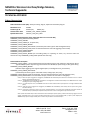
TECHNICAL APPENDIX
Z-Wave Characteristics
Node Information Frame (NIF): ‘Always Listening’ flag set, ‘Optional Functionality’ flag set
Manufacturer ID
Product Type ID
Generic Device Class
Specific Device Class
0x0084
0x0453 (US)
0x0451 (EU)
GENERIC_TYPE_SWITCH_BINARY
SPECIFIC_TYPE_NOT_USED
Supported Command Classes (these supported classes are sent in the NIF)
COMMAND_CLASS_MANUFACTURER_SPECIFIC
COMMAND_CLASS_VERSION
COMMAND_CLASS_ALARM (V1, for power fail)
COMMAND_CLASS_SENSOR_BINARY
COMMAND_CLASS_SENSOR_MULTILEVEL ('General Purpose Value' type for SIG1 analog ADC Count)
COMMAND_CLASS_METER_PULSE (count incremented based on each new triggering event at SIG1)
COMMAND_CLASS_CONFIGURATION
COMMAND_CLASS_ASSOCIATION
COMMAND_CLASS_SWITCH_BINARY (for controlling Relay1 or reporting its status; any non-zero value will
activate the relay; COMMAND_CLASS_BASIC operates the same way)
Command Class Description
COMMAND_CLASS_ALARM – sends unsolicited reports (association group 3) and responds to Gets with an Alarm
Type of 0x08 (for power drop warning) and an Alarm Level of 0x00 (no power drop) or 0xFF (power drop)
COMMAND_CLASS_SENSOR_BINARY
(Indicates input triggering state: high for digital inputs; see Configuration CC, parameter 8)
COMMAND_CLASS_SENSOR_MULTILEVEL
('General Purpose Value' type for 12-bit ADC Counts; analog input, SIG1, only)
COMMAND_CLASS_METER_PULSE (for input SIG1; count incremented based on each new triggering event)
COMMAND_CLASS_ASSOCIATION - Five Association Groups; maximum of two nodes in each group.
Group 1: When the input is triggered or untriggered, the MIMOlite will automatically send a Basic Set command to turn on or off the
device(s) associated with this group.
Group 2: The MIMOlite will periodically (see Parameter 9 of Configuration Command Class below) send a MultiLevel Sensor report
indicating the input’s analog voltage level.
Group 3: If a power dropout occurs, the MIMOlite will send an Alarm Command Class report (if there is enough available residual
power)
Group 4: When the input is triggered or untriggered, the MIMOlite will automatically send a Binary Sensor report to this group’s
associated device(s).
Group 5: Pulse meter counts will be sent to this group’s associated device(s). This will be sent periodically at the same intervals as
Association Group 2, MLS Report except that if the pulse meter count is unchanged the report will not be sent.
Notes: a) MLS Association Groups 2 and 5 transmissions do not attempt an explorer frame, if nodes do not ACK; b) If triggers occur too
quickly, Association Group 1 or 4 reports can block transmissions if sent to a non-responding node; c) Upon a power dropout, the
MIMOlite likely only has enough residual power to send to the first node in Association Group 3.
1080 Centre Rd. Ste C
Auburn Hills, MI 48326
www.fortrezz.com
Phone: (248) 481-7092
[email protected]
Made in USA
070713
MIMOlite Wireless Interface/Bridge Module,
Technical Appendix
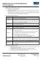
COMMAND_CLASS_CONFIGURATION (all parameters are one byte unsigned values or can be considered as a
commanded, signed value with an offset of 128)
Parameter 2 is for input SIG1 only.
Parameter 3 (input to relay mapping) and Parameter 11 only apply to the Relay1 output. Parameters 410 are for input SIG1 only.
Parameters 4-7 are for analog input characteristics only. The 8-bit thresholds below are used for
determining triggering and represent the upper 8 most-significant bits (with lower 4 bits of threshold set
to 0) for comparison to the 12-bit Analog-to-Digital converted value.
Configuration Command Class Parameters
Parameter 1
Not Used
Clear Pulse Meter Counts (actual value is “don’t care”; count gets reset whenever
Parameter 2
this command is received regardless of value)
Trigger Mapping: 1 = SIG1 triggered/untriggered sets or clears Relay1 (Default=0x00;
Refer to description in User Manual under section, Input to Relay Mapping) Note
Parameter 3
that neither a Basic Report nor a Binary Switch Report is sent when relay is
automatically set or cleared by Trigger Mapping.
Lower Threshold, High (Default=0xBB; must be less than Upper Threshold Low and
Parameter 4
greater than Lower Threshold Low)
Parameter 5
Lower Threshold, Low (Default=0xAB)
Parameter 6
Upper Threshold, High (Default=0xFF)
Upper Threshold, Low (Default = 0xFE; must be greater than Lower Threshold High
Parameter 7
and less than Upper Threshold High)
Input Flags: Bits 7 - 2 are ignored and should be set to 0
Parameter 8
Parameter 9
Parameter 10
Parameter 11
Bit1 : Digital-Configuration flag
1=Set Trigger levels for this channel to ‘digital’ thresholds (approx. 1V); Default
0=Set Trigger levels to analog thresholds (see parameters 4 through 7)
Bit0 : Trigger-Between-Thresholds flag (see below)
1 = Set to ‘triggered’ when input falls between thresholds; Default
0 = Set to ‘triggered’ when input falls outside of thresholds
Periodic send interval of Multilevel Sensor Reports (Association Group 2) and/or
Pulse Count Reports (Association Group 5) for SIG1. This parameter has a resolution
of 10 seconds; for example, 1 = 10 seconds, 2 = 20 seconds, 3 = 30 seconds (Default),
…, 255 = 2550 seconds = 42.5 minutes. A value of 0 disables automatic reporting.
Not used
Momentary Relay1 output enable/disable. 0 = disable (Default)
1..255 = enable / value sets the approximate momentary on time in increments
of 100msec.
Behavior when commands are received
Received Binary Sensor Gets will cause SIG1 Binary Sensor Report value (Triggered = 0xFF,
Untriggered = 0x00) to be reported
Received Multilevel Sensor Gets will cause 12-bit value for SIG1 to be reported
Received Basic Gets will cause Relay1 Basic Report (binary switch value) to be reported
Received Basic Sets will cause Relay1 binary switch to be set
1080 Centre Rd. Ste C
Auburn Hills, MI 48326
www.fortrezz.com
Phone: (248) 481-7092
[email protected]
Made in USA
070713
MIMOlite Wireless Interface/Bridge Module,
Technical Appendix
Self-Test
Caution: Self-test will overwrite all settings and take the MIMOlite out of the network!
Self-Test Entry: Hold the Program button while powering up the MIMOlite.
Indication: The Status LED will remain lit while the button is held.
Test 1: EEPROM test – The software will write bytes to the application EEPROM area, delay a second, and then attempt to
read them back.
Indication: If the EEPROM test is successful, the SIG1 LED will light (faintly). If the EEPROM test is not successful,
the Status LED will light and stay lit; no more tests will be performed. Note that this test erases EEPROM memory;
thus, all Configuration Command Class setups will be erased.
Test 2: Software verification test – The software will run a checksum on its program memory area.
Indication: If the Software verification test is successful, the SIG1 LED will turn off. If the Software verification test
is not successful, the Status LED will light and stay lit; no more tests will be performed.
Test3: Relay test – The software will attempt to turn on Relay1 twice.
Indication: Relay clicks should be heard.
Test 4: RF output should start and continue for 2 seconds.
Indication: The SIG1 LED will turn on during this test; check RF output with spectrum analyzer
Notes:
1) The tests go in sequence quickly.
2) After Test 4 is complete, the MIMO will reset and start normal operation.
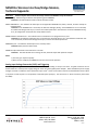
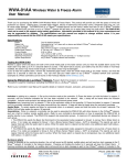
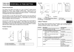
Analog Input Voltage Conversion (SIG1) and Triggering
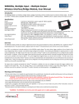
The input signal voltage conversion to Multilevel Sensor value (ADC reading or count) is non-linear. A typical conversion curve is
shown below for a nominal power supply voltage of 13.5V using the supplied power adapter. Note that different power supply
voltages will result in a different value reported for open circuit. These are the values returned via the Multilevel Sensor report
in response to a Get request or in the periodic, associated reports (Group 2). The conversion is a 12-bit conversion (values from
0 to 4095).
1080 Centre Rd. Ste C
Auburn Hills, MI 48326
www.fortrezz.com
Phone: (248) 481-7092
[email protected]
Made in USA
070713
MIMOlite Wireless Interface/Bridge Module,
Technical Appendix
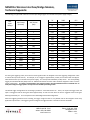
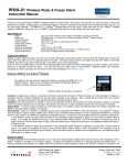
The following are typical ADC values for various input voltages (again at a nominal 13.5V power supply voltage).
SIG1
Input
Voltage
ADC Counts
(decimal)
ADC Counts
(hex)
Open
Shorted
2162
7
872
7
0V
0.5V
1V
1.5V
2V
2.5V
3V
3.5V
4V
4.5V
5V
5.5V
6V
6.5V
7
631
1179
1687
2062
2327
2510
2640
2741
2823
2892
2953
3004
3051
7
277
49B
697
80E
917
9CE
A50
AB5
B07
B4C
B89
BBC
BEB
7V
7.5V
8V
8.5V
9V
9.5V
10V
11V
12V
13V
14V
15V
16V
17V
18V
19V
20V
21V
22V
23V
24V
3093
3132
3167
3200
3231
3260
3286
3336
3380
3420
3458
3492
3523
3552
3580
3607
3633
3656
3678
3699
3717
C15
C3C
C5F
C80
C9F
CBC
CD6
D08
D34
D5C
D82
DA4
DC3
DE0
DFC
E17
E31
E48
E5E
E73
E85
For setting the triggering values, the lower four least-significant bits are dropped so that the triggering configuration value
is an 8-bit value (0 to 255 counts). For example, to set a trigger at approximately 2 Volts, the conversion will read approx.
2057 decimal counts (at a nominal 13.5V power supply). This corresponds to 808 hex (12-bit) counts. The corresponding
trigger point would be 80 hex (8-bit) counts or 128 decimal because the lower 4 bits would be dropped in order to set the
trigger configuration. It is highly recommended to test triggering points using the Multilevel Sensor Command class to
verify that configured trigger points correspond to the desired input voltage levels.
The default trigger configuration for the analog input SIG1 is a threshold around 1V. That is, the inputs will trigger when the
input is untriggered and the level goes above approximately 1V and will reset when the level is triggered and the level goes
below approximately 1V. This corresponds to the default digital threshold configuration.
When the triggering threshold is set to Analog, the trigger ranges for SIG1 are very flexible and can be changed to meet many
application requirements. The triggering can be configured to trigger between or outside of the two thresholds.
1080 Centre Rd. Ste C
Auburn Hills, MI 48326
www.fortrezz.com
Phone: (248) 481-7092
[email protected]
Made in USA
070713
MIMOlite Wireless Interface/Bridge Module,
Technical Appendix
Also, a hysteresis can be configured for each endpoint of the range so that the input is not constantly triggering and untriggering
due to small changes in input voltage.
These triggering ranges are configured using the Configuration Command Class, Parameters 4 through 8. Refer to the
Configuration Command Class Parameters section above for details about these parameters.
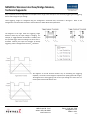
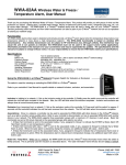
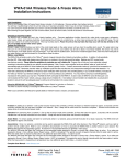
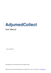
The diagrams to the right show the triggering ranges
based on which way the input voltage is changing. For
example, if ‘Trigger between Thresholds’ is enabled, then
the input will trigger when the voltage rises across the TLH
threshold. Similarly, the input will ‘untrigger’ (if already
triggered), and the voltage falls across the TLL threshold.
The diagrams at the left illustrate another way of considering this triggering
capability. The X-axis in these diagrams represent time passing (from left to right).
The diagrams show the triggering state as the input voltage rises from zero to a
certain point and then falls back to zero.
1080 Centre Rd. Ste C
Auburn Hills, MI 48326
www.fortrezz.com
Phone: (248) 481-7092
[email protected]
Made in USA
070713
MIMOlite Wireless Interface/Bridge Module,
Technical Appendix
Input-to-Relay Mapping
The MIMOlite can be configured to automatically turn the relay on when the input (SIG1) is triggered.
The
Configuration Command Class, Parameter 3, is used to set this mapping. When this mapping is enabled, Z-WaveTM
commands to set a relay are overridden. The default for the relay is no input-to-relay mappings. Note that when
relay mapping is enabled, no Z-WaveTM notification is given if the relay sets or resets. However, the relay state can
be queried by the using the Basic Command Class Get command or the Binary Switch Command Class Get command.
Parameter 3, SIG1 to RELAY1 mapping, is enabled by setting Bit 0 in the parameter value field and disabled by
clearing the same bit.
POWER DROPOUT
A periodic Power Dropout status blink (see above indication table) is shown if the supplied power drops below
approx. 10.5 Volts. In addition, the MIMOlite implements the Alarm Command Class (Version 1), which provides for
an alarm report (Alarm Type = 0x08, Alarm Level = 0xFF) to be sent when the supplied power drops. The MIMOlite
sends the notification to the node(s) in Association Group 3. After a power dropout alarm event, the MIMOlite
sends an alarm report (Alarm Type = 0x08, Alarm Level = 0x00) when the supplied power rises above approx. 11
Volts.
If the supplied power drops, the MIMOlite attempts to save the pulse count in non-volatile memory. This is a
memory area that remains valid when no power is applied. It stores ‘check’ information along with the pulse counts
so that when power is reapplied, it is known whether the pulse counts are valid and can be restored.
For sending the alarm signal and storing pulse counts in non-volatile memory, the MIMOlite relies on residual power
in the MIMOlite circuitry when power completely drops out. Typically, this will be sufficient to perform both of
these actions. If power drops quickly enough, MIMOlite attempts to store the pulse counts prior to sending the
alarm signal.
Even though the MIMOlite will attempt the above power dropout actions, it is not guaranteed that they will
complete. Thus, it is highly recommended that you take any steps you deem necessary to avoid data loss. This
could include providing an external backup battery for the MIMOlite, configuring your controller to periodically poll
the MIMOlite for the latest pulse counts, etc.
Information provided in this technical appendix is for your convenience and may be superseded by
updates. The specifications and this manual are subject to change without notice. It is your
responsibility to ensure that the MIMOlite functionality meets your needs and specifications.
For warranty information, please refer to ‘Limited Warranty’ section in User Manual.
1080 Centre Rd. Ste C
Auburn Hills, MI 48326
www.fortrezz.com
Phone: (248) 481-7092
[email protected]
Made in USA
070713