1
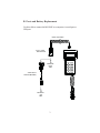
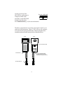
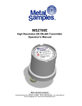
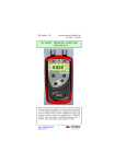
MS1500E
Data Logger
(Version 1)
Metal Samples Corrosion Monitoring Systems
152 Metal Samples Rd. Munford, AL 36268
Phone: (256) 358-4202 Fax: (256) 358-4515
E-mail: [email protected]
Internet: www.metalsamples.com
Houston Office: 6327 Teal Mist Lane, Fulshear TX 77441
Phone: (832) 451-6825
.
Table of Contents
I.
Introduction ..................................................................... 1
A. General Description ..................................................... 1
B. Ports and battery replacement ...................................... 3
C. Specifications ............................................................... 5
II.
Operation .......................................................................... 7
A. Select probe ID ............................................................. 9
B. Make measurement ..................................................... 12
C. Compute MIL/MPY .................................................... 14
D. Recall readings ............................................................ 15
E. Delete readings ............................................................ 15
F. Communications .......................................................... 16
G. Set time and date ......................................................... 26
H. Test mode ................................................................... 26
III. Theory of Operation ....................................................... 27
A. Measurement theory .................................................... 27
B. ER sensing elements ..................................................... 28
C. ER element performance .............................................. 31
D. ER probe body design ................................................. 35
1. Fixed length ER probe ............................................ 36
2. Retractable ER probe ............................................. 37
3. High pressure retrievable ER probe ......................... 38
IV. Testing the MS1500E with the ER Meter Prover ........ 39
V.
Returning an Instrument for Repair .............................. 41
VI. Warranty ......................................................................... 43
.
I. Introduction
A. General Description
The MS1500E is an intrinsically-safe, battery-powered, hand-held
corrosion meter that enables you to directly take measurements from an
electrical resistance probe, store the data, and upload directly to a
computer. The unit features an easy-to-use Main Menu that will permit
even an operator who is unfamiliar with the unit to take readings with
ease.
Corrosion rate measurements are made using the electrical resistance method. The electrical resistance method has a wide range
of applications since it can be used in conductive or nonconductive
environments including oil and gas. The unit measures the change
in resistance of the probe element as metal loss occurs. The rate of
change is directly proportional to the corrosion rate.
After taking and storing a reading, the operator can display the
metal loss in mils and the corrosion rate in mils per year (mpy). All
measurements made with the unit are automatically time and date
stamped with the MS1500E internal real time clock. If the
MS1500E detects a probe with an internal leak or damaged element, a CHECK FAILED message occurs. The unit can take up to
3,100 readings and can be used with up to 150 probes. All stored
readings are protected by a lithium back-up battery to prevent loss.
Data may be selectively deleted from memory to accommodate
additional information once the 3,100 reading capacity is reached.
Alternatively, information may be downloaded to a PC as a comma
delimited ASCII file for import into any of the standard data handling
and analysis programs (e.g., EXCEL®, LOTUS 123®, Quattro
Pro®).
1
The MS1500E may also be used as a data collection and transfer
terminal for the MS3500E remote data logger. Accumulated data
from several MS3500E field-based units may be locally downloaded to the MS1500E hand-held terminal, and then transferred to
a PC for further analysis.
The MS1500E offers seven operating modes:
• Select Probe ID
• Make Measurements
• Compute
• Recall
• Delete Readings
• Communicate
• Set Time and Date
All electrical resistance probe types can be used with this unit, including
wire loop, tube loop, cylindrical element, surface strip, and flush mount
probes.
2
B. Ports and Battery Replacement
Use this cable to connect the MS1500E to a computer via serial port or
USB port.
COILED DATA CABLE
MS1500 SERIAL
PORT ADAPTER
TO
COMPUTER
SERIAL
PORT
SERIAL TO USB
ADAPTER (OPTIONAL)
TO
COMPUTER
USB
PORT
3
Use the port on top of the
Top view of MS1500E
MS1500E for connecting to a
computer (with the cable
provided) or to the MS3500E
(with the Opti-link cable.)
See Communications (p. 16) for more information.
The battery compartment is accessed by removing the “slip-fit” cover
on the rear of the instrument. Three 1.5VDC, AA size, dry cell batteries are placed in the spring loaded holders, following the plus/minus
orientation indicated on the battery holder as illustrated below.
FRONT
BACK
"SLIP-FIT" BATTERY COVER
POWER SWITCH
3 X 'AA' ALKALINE BATTERIES
(DURACEL MN1500 OR PC1500
REQUIRED FOR INTRINSIC SAFETY.)
PROBE CONNECTOR
4
C. Specifications
ER Probe Configurations
Wire Loop
Tube Loop
Cylindrical Loop
Flush Mount
Surface Strip
Battery:
Three 1.5 Volt AA alkaline batteries
Battery Life:
8 hours of continuous use
Temperature Range:
32° to 120°F (0° to 49°C)
Operational
Humidity Range:
30% - 90%
Storage
Humidity Range:
5% - 95%
Memory Protection:
10-year battery, back-up life
Measurement/
Computations:
Probe Life (0 - 100%)
Metal Loss (Mils)
Corrosion Rate (Mils/Year)
Display:
4 lines x 20 characters LCD panel
Maximum # of
probe storage files:
150
Maximum # of
stored readings:
3,100
5
Operating modes:
Select probe ID (select/enter/delete probe ID)
Make measurement
Compute (metal loss and corrosion rate)
Recall readings
Delete readings
Communicate (upload/download)
Set time and date
Communication port:
RS-232 serial port
Dimensions:
7.5" length x 4.0" width x 2.0" depth
Weight:
1.5 lbs (5.2 lbs. with hardshell case)
Intrinsic Safety:
Class I, Division 1
Groups A, B, C, and D
Temperature Code T3C
Class I, Zone 0
Group IIC, T3C
Conforms to ANSI/UL Std. 913
6
II. Operation
Storage capacity
The MS1500E allows you to measure metal loss and corrosion rate.
Review this section which describes
the functions that display on the
Main Menu:
The MS1500E allows a
maximum of 3,100 readings
with up to 150 probes.
• Select probe ID
• Make measurement
• Compute MIL/MPY
• Recall readings
• Delete readings
• Communications
• Set time & date
• Test mode
To increase your free
storage, which displays in the
start-up screen, select from
the Main Menu:
• DELETE READINGS
or
• SELECT PROBE ID
and then
DELETE PROBE
or
ENTER NEW PROBE
When you power up the MS1500E,
the start-up screen confirms these
checks:
• the software version
currently running
• free storage available (see
Storage capacity in
margin)
• system test pass
The last display of the start-up
screen looks like this:
METAL SAMPLES
MS1500E VX.X
SYSTEM TEST : PASS
7
If you want to know how much
storage is currently available, carefully watch the start-up screen which
displays this information quickly
before SYSTEM TEST PASS; then
the Main Menu displays.
Screen 1 of the Main Menu looks
like this:
SELECT PROBE ID
MAKE MEASUREMENT
COMPUTE MIL/MPY
RECALL READINGS
Screen 2 of the Main Menu looks
like this:
DELETE READINGS
COMMUNICATIONS
SET TIME & DATE
TEST MODES
To run a function, select it by using
the up or down arrow and pressing
ENTER. While in the Main Menu,
pressing EXIT will return the selector icon to the first item of the Main
Menu.
8
A. Select Probe ID
The SELECT PROBE ID function
allows you three options:
Select a probe before you
run a function
In order for you to make
measurements, compute
mil/mpy or recall or delete
readings, you must select
a probe that is currently in
memory.
The MS1500E provides
you with a list of probes in
memory; use the arrow
key to select one and press
enter. Now you’re ready
to run any other function.
• select a probe already in
memory for which you wish to
run any other feature of the
MS1500E (Make Measure
ment, Compute mil/mpy,
Recall Readings, or Delete
Readings);
• enter into memory the identifi
cation of a new probe
• delete from memory the
identification of a probe
To run any of these three options,
choose SELECT PROBE ID from
the Main Menu.
SELECT PROBE ID
MAKE MEASUREMENT
COMPUTE MIL/MPY
RECALL READINGS
The next screen allows you to choose
the functions to ENTER or DELETE
a probe ID or to select a probe ID
from those already in memory for
which you wish to make measurements.
9
To assist you with selecting a probe
ID, the screen displays a list of all
probe IDs currently in memory.
Entering information
To enter a number, type it
using the keypad numbers.
Select from the list of probes in
memory the probe for which you
wish to run a function (Make Measurement, Compute mil/mpy, Recall
Readings, Delete Readings).
If you make an error,
press the down arrow this allows you to type the
number again.
Pressing the up arrow
retains the ID number you
typed in.
Entering probe type
The MS1500E has a list of
probe types in memory.
Select one by pressing the
arrow keys. (See Appendix B for a list of probe
types supported by the
MS1500E.)
ENTER NEW PROBE
DELETE PROBE
1234 WIRE 40
4567 FLUSH 20
1. Press the arrow key to select a
probe ID.
2. Press ENTER.
To enter the ID of a new probe,
select ENTER NEW PROBE; the
next screen allows you to enter the
ID number and the type.
1. Enter the probe ID - use the
number keys (press the DOWN
arrow if you make an error).
2. Press the UP arrow when you’ve
entered the correct ID number.
3. Enter probe TYPE (see margin).
4. Press ENTER.
10
PROBE ID: 5385
PROBE TYPE: WIRE 40
USE ARROW KEYS
Deleting probes
It’s necessary to delete a
probe when you replace
one. Note that when you
delete a probe, you also
delete all the readings for
that probe.
You might want to transfer
the readings to a computer before deleting them
by using the
COMMUNICATIONS
option in the Main Menu.
(See Communications, p.
16.)
It is occasionally necessary to remove the ID of a probe from
memory, for example:
• when the memory bank is full
• when a probe is no longer used
To delete the ID of a probe in
memory, select DELETE PROBE.
DELETE PROBE
PROBE ID:
UP ARROW WHEN DONE
1. Enter the probe ID - use the
number keys (press the DOWN
arrow if you make an error).
2. Press the UP arrow when you’ve
entered the correct ID number.
The instrument will confirm your
choice of probe ID before deleting it
from memory.
11
B. Make Measurement
To take measurements from probes
in memory, select MAKE MEASUREMENT from the Main Menu:
Select a probe before you
run the function
In order for you to run
MAKE MEASUREMENT,
you must have already
selected a probe from
memory.
See Select Probe ID from
the Main Menu (see page
9).
SELECT PROBE ID
MAKE MEASUREMENT
COMPUTE MIL/MPY
RECALL READINGS
The next screen displays the Probe
ID that you selected earlier from the
Main Menu item
SELECT PROBE ID.
Set time and date
To ensure readings you
make are accurate, be sure
the time and date settings in
the MS1500E are correct
(see page 26).
PROBE ID: 1234
PRESS ENTER TO START
When you press ENTER, the
MS1500E checks the probe for
correct operation. The next screen
then displays the results of that check
as PASSED or FAILED.
12
If the probe failed the test, this
screen displays:
PROBE ID: 1234
PROBE CHECK FAILED
PRESS EXIT
Check failed = bad probe
When a probe fails this
test and the screen
displays CHECK
FAILED, it means the
probe may have either a
damaged element or an
internal leak.
Press EXIT to return to the Main
Menu.
If the probe passed, this screen
displays:
Replace a probe that
results in a CHECK
FAILED.
PROBE ID: 1234
PROBE CHECK PASSED
PRESS ENTER TO READ
Press ENTER to view the reading:
PROBE ID: 1234
READING: 124
PRESS ENTER TO SAVE
Press ENTER to save the reading in
memory. Saved readings also
include the date.
Press EXIT to return to the Main
Menu.
13
C. Compute MIL/MPY
Select a probe before you
run a function
In order for you to run
COMPUTE MIL/MPY,
RECALL READINGS or
DELETE READINGS,
you must have already
selected a probe from
memory.
Select COMPUTE MIL/MPY to
review data from the last reading on
a probe. The MS1500E calculates
these data from a comparison between the last reading and the first
reading on the probe:
20/01/98 TO 20/02/98
MET LOSS: 0.05 MIL
COR RATE: 0.59 MPY
PRESS EXIT
See Select Probe ID from
the Main Menu (see page
9).
Press EXIT to return to the Main
Menu.
14
D. Recall Readings
Select RECALL READINGS to look
at data from different dates. Use the
arrow keys to choose the reading
number. Or press ENTER to type in
the number on the keypad.
READING #: 2
DATE: 20/02/98
READING: 124
DOWN/UP/EXIT/ENTER
Press EXIT to return to the Main
Menu.
E. Delete Readings
Select DELETE READINGS to
erase a reading from memory. Periodically delete readings to create
more free storage area in memory.
DELETE READINGS
#1 20/01/98 125
#2 20/02/98 125
ENTER TO DELETE
Press EXIT to return to the Main
Menu.
15
F. Communications
The MS1500E Data Logger has the ability to store readings as they are
taken. These readings can later be transferred to your PC via serial
port or USB port. To transfer data to a PC it is necessary to install the
Corrosion Data Management Software.
Installing the Software
To run the Corrosion Data Management Software, you need a PC that
meets the following requirements:
•
•
•
•
•
•
•
•
Pentium® class processor
Windows® 95 or higher operating system
16 MB of RAM
10 MB of available hard-disk space
VGA monitor with 800 600 or greater resolution
Mouse or pointing device recommended
Available 9-pin serial port or USB port
CD-ROM drive for software installation
To install the Corrosion Data Management Software:
1. Insert the setup disk provided in your accessory kit.
2. You will be prompted to close any open programs. After you
have done so, click OK to continue.
16
3.
Click the install button to begin installation. Note, it is recommended
that you install the software in the default directory.
4.
After clicking the install button, the software will be installed on your
PC.
5.
When the software installation is complete you should remove the
setup disk, then reboot your computer.
17
Instrument Download Center
The Instrument Download Center is a simple tool for retrieving data
from Metal Samples ER and LPR data logger instruments.
To download data from an instrument:
•
•
•
•
•
•
•
•
Connect the instrument to an available PC serial port or USB
port (see page 3.)
Turn the MS1500E on.
Run the Corrosion Data Management Software
Open the Instrument Download Center
Select the serial port and instrument
Click the Download button (ensure that Part Status toggles to
“On”).
From the main menu of the instrument, go to the Select Probe
I.D. menu and select the probe data you wish to download.
From the main menu of the instrument, go to the Communications menu and select Computer Upload.
Data will begin to transfer from the instrument to the PC, and will
appear in the data window of the Instrument Download Center as
shown above. If the data appears garbled, the wrong instrument type
has been selected. Select another instrument type and try again. If data
does not appear in the data window at all, verify that:
18
•
•
•
•
•
The instrument is connected to a valid serial or USB port
All cables are securely connected
The message “Port Status: On” appears in the status bar
There are no errors on the instrument
If using a USB adapter, ensure that the device drivers have
been installed.
Selecting a Serial Port
Use the Serial Port selection box to select the port to which the
instrument is connected. If the COM port number is unknown, it can
be found in Windows Device Manager under “Ports (COM & LPT)”.
Selecting an Instrument
Use the Instrument option box to select the model of Metal Samples
instrument being downloaded. This sets the appropriate communication
parameters, which will be displayed in the status bar at the bottom of
the window (“9600,N,8,1” for an MS1500, “2400,N,8,1” for an
MS3500).
Downloading Data
To toggle the selected port on and off, click the Download button.
Toggling the port on and off will also clear the data window.
Once a valid serial port and instrument have been selected, click the
Download button to turn the port on and enable the computer to
receive data. If a valid serial port has been selected, the status bar at
the bottom of the window will display the message “Port Status: On”.
If an invalid serial port has been selected, an error message will appear,
and the status bar will display the message “Port Status: Off”. If this
happens, another serial port should be selected.
19
Saving Data
To save the data in the data window, click the Save button. The data is
comma-delimited ASCII text. It can be saved to a standard text (.txt)
file, or it can be saved to a comma-separated values (.csv) file, which
greatly simplifies the process of importing the data into some spreadsheet programs such as Excel® or Quattro Pro®.
Printing Data
To print the contents of the data window, click the Print button. A print
dialog box will be displayed to allow printer selection and setup.
Charting Data
To chart the contents of the data window, click the Chart Data button.
If the data has not yet been saved, the user will be prompted to do so
before the charting process begins. For more information on charting
data, see the Data Analysis section.
Data Analysis
The Data Analysis utility is a convenient tool for charting data from
Metal Samples ER and LPR data logger instruments. The Data Analysis utility can be opened from the Main Menu, or it can be opened
directly from the Instrument Download Center.
If the Data Analysis utility is opened from the Instrument Download
Center, the contents of the data window will be loaded into the chart.
However, if the Data Analysis utility is opened directly from the Main
Menu, a valid data file must be loaded. The Select File box will open
to allow selection of a data file.
20
Loading a Data File
After selecting a data file (or clicking the Chart Data button from the
Instrument Download Center) a status window will display the progress
of the file being opened, along with the Instrument Type, Probe Type,
and Probe ID for the data file.
Data Table
After a file has been successfully loaded, the data will be displayed in
the Data Table for review. By default, all data points will be included in
the chart. However, data points can be turned off, or excluded, from
the chart. If the “Excluded” flag appears in the status column for a data
point, that data point will not appear in the chart. To toggle the exclude/
include status of a data point, double-click the data point, or select the
data point and click Exclude/Include in the Options menu.
Printing Data
The data table can be printed by clicking Print in the Options menu. A
print dialog box will be displayed to allow printer selection and setup.
21
Creating A Chart
To chart the selected data, click the Chart Data button, or select
Chart Data from the Options menu. The chart will be displayed in a
new window.
Printing a Chart
A chart can be printed using the Print Chart option in the File menu.
A print dialog box will be displayed to allow printer selection and setup.
Exporting a Chart
A chart can be exported to other applications using the Copy Chart
option in the File menu. This will copy both the chart and the raw data
to the Windows® Clipboard. The chart can then be inserted into other
applications using the Paste function. Note: In some applications,
using the Paste function will insert the raw data instead of the chart. In
this case, use the Paste Special function, then select Picture to insert
the chart.
Chart Tools
• Statistical Data
The Statistical Data tab at the bottom of the Data Chart window
will display a page with statistical information about the chart data.
If the Statistical Data page is visible, this information can be printed
by clicking Print Statistical Data in the File menu.
22
•
Finding A Data Points Value
While viewing the chart, the value of any data point can be
determined by simply clicking it. The value will be displayed in the
charts tool-tip box (a small text box that is displayed near the
mouse pointer). If the tool-tip box does not appear immediately
after clicking the data point, hold the mouse pointer stationary over
the chart background for a moment.
•
The Tools Menu
The Tools menu contains a collection of utilities for viewing and
manipulating the chart. The Tools menu can be accessed by
clicking Tools on the menu bar, or by right-clicking anywhere on the
chart.
o Data Markers
Show Data Markers toggles the data markers on and off.
o Mean Value
Show Mean Value toggles the mean value line on and off.
o Trend Line
Show Trend Line toggles the trend line on and off.
23
o Title/Footnote Setup
Title/Footnote Setup displays a window that allows the
chart title and footnotes to be toggled on and off, and to be
modified.
o Plot Setup
Plot Setup displays a window that allows configuration of
Y-axis scaling, and of the chart type.
The Y-axis can be scaled to default values by checking the
Auto Scaling option box. The Y-axis can be scaled to
manual values by un-checking the Auto Scaling box, then
entering the desired values in the Minimum and Maximum
fields.
The chart type can be set to Line Chart, Bar Chart, or
Area Chart by selecting the appropriate button in the
Chart Type box. The default chart type is Line Chart.
o Data Series Color
Data Series Color displays a color selection box, which
allows the user to select the brush color for the plot line.
The default color for the plot line is Blue.
o Zoom In
Zoom In allows a region of the chart to be enlarged so that
it may be viewed in greater detail. To enlarge a region of
the chart, click on the two data points that define the left
and right boundaries of the region.
In zoom mode, the mouse pointer will change to a crosshair. When zoom mode ends, the mouse pointer will return
to its normal state.
To cancel zoom mode, click Cancel Zoom In from the
Tools menu, or simply press the Esc key.
24
o Zoom Out
Zoom Out restores the initial view of the chart, which
displays the full data set.
o Calculate Corrosion Rate
If the chart contains ER data, the Calculate Corrosion
Rate option will become available under the Tools menu.
This option allows the corrosion rate to be calculated
between any two data points on the chart. To calculate the
corrosion rate click Calculate Corrosion Rate, then click
two data points. The corrosion rate between those two
data points will be displayed.
In calculate mode, the mouse pointer will change to an
arrow/question mark. When calculate mode ends, the
mouse pointer will return to its normal state.
To cancel a calculation, click Cancel Calculate from the
Tools menu, or simply press the Esc key.
25
G. Set Time and Date
Caution
The time and date are set
at the factory, but may
need to be adjusted to your
time zone.
Also, if you try to change
the date or time and it
conflicts with stored
information, the MS1500E
will display N/A.
When you need to set the internal
clock, select SET TIME & DATE.
In order for information in memory
to be useful and accurate, be sure the
time and date are accurate.
SET TIME & DATE
11:46 AM 20/02/98
ENTER TO ACCEPT
Use the numbers on the keypad and the
arrow keys to make changes to the time
and date.
Note: The MS1500E uses the international date format (DD/MM/YY). Be
Sure to enter the date in this format to
prevent errors in data handling and
calculations.
Press ENTER to confirm your changes
and to return to the Main Menu, or
press EXIT to discard your changes.
H. Test Mode
This function of the instrument is
used by authorized factory personnel
for servicing or upgrading the
MS1500E.
E
2939 O153R1364 O151
G57
RATIO 0.4641
READING: 122
#105
PROBE: 1234-WIRE 40
26
III. Theory of Operation
A. Measurement Theory
The reduction in cross-sectional area of an element of metal or
alloy as it corrodes is accompanied by a corresponding increase in
the electrical resistance of the element.
The relationship is given by
R=
x L/A .............................(1)
R = element resistance
= specific resistivity of the element alloy
A = element cross-sectional area
L = element length
Consequently, periodic resistance measurements of a metal/alloy
element that is continuously exposed to a corrosive environment,
will provide data on the rate and extent of corrosion for that alloy/
environment combination.
In practice, resistance is also a function of temperature. Therefore,
electrical resistance corrosion sensors need some means to compensate for the effects of temperature change. This is achieved by
constructing the sensors such that the sensing element has an
exposed portion that freely corrodes and a protected portion that is
within the body of the sensor and not subject to corrosion. Such a
construction is illustrated in Figure 1.
Figure 1: Temperature compensated element
27
The resistance of both the exposed (RE) and protected (RT) portions
of the sensors are equally influenced by temperature. Consequently, the resistance ratio of the exposed to protected elements is
a function only of the loss in metal thickness on the exposed
element, and therefore of corrosion.
This resistance ratio (RE/RT) is measured either periodically with a
portable instrument, or continuously with a variety of continuous,
automatic recording/data logging instruments and read as percentage thickness loss. Thus, total metal loss versus time is directly
available, and corrosion rate is indirectly available as the slope of
the line for metal loss versus time.
Figure 2: Typical data
28
B. ER Sensing Elements
Electrical resistance probe elements are offered in a variety of
thicknesses and geometries. The most common are illustrated
below:
Wire Loop
Cylindrical
Tube Loop
Flush
Figure 3: Element styles
Tubular loop elements are constructed from thin-walled tubing.
Their small cross-section allows fast response at low corrosion
rates.
Wire loop elements, constructed of solid wire, provide a good compromise between sensitivity and long life. They are typically used for
systems exhibiting moderate corrosion rates (5-20 mpy).
Cylindrical elements are made from hollow cylinders and are
extremely robust. They are widely used in high temperatures and
high flow rate conditions. They tend to be sensitive to noise and
somewhat sluggish in response. Consequently, they are only
recommended for moderate to high corrosion rates (20-50 mpy).
Flush elements are designed to be located flush with the corroding
surface of the vessel/pipe, consequently, most closely simulating
true corrosion rates. The flush element is useful in high flow
regimens and operating conditions where internal obstructions are
not permissible, e.g. pigged pipelines.
The mechanism for sealing elements into probe bodies varies. For
example, the cylindrical type elements are sealed with an all metal
weld, whereas flush elements are sealed with an epoxy seal.
29
The sealing mechanism of the element is a primary factor in determining
the temperature and pressure rating of an ER probe.
Table 1 provides a guide to temperature and pressure limitations for
various element designs.
Ele me nt
Form
Pre s s ure
Rating PSI
Te mpe rature
Rating °F / °C
TU04
TU08
1500
500 / 260
40 mil
80 mil
WR40
WR80
1500
500 / 260
cylindrical element
all metal
10 mil
20 mil
CT10
CT20
1500
500 / 260
flush element
epoxy seal
5 mil
10 mil
FM5
FM10
1500
400 / 204
Thickne s s
Ele me nt ID
tubular loop
glass sealed
4 mil
8 mil
wire loop
glass sealed
Table 1: Element temperature and pressure ratings
The temperature and pressure limitations given above may be
subject to modification according to the probe body design. This is
discussed later in this manual.
A final issue with respect to sensing elements is material of construction. Generally, this should be selected to most nearly match
that of the plant or equipment under consideration.
Almost any geometric configuration and thickness of element can
be made in any commercially available alloy. However, some
alloys, particularly in the glass sealed loop version, may be costly
and have a considerable delivery time.
30
C. ER Element Performance
The basic ER measurement gives percentage of metal thickness
loss and is a function of the original element thickness. Essentially, total metal loss and corrosion rate are given by the following
functions:
ML
X
X2
X1
t
CR
K
=
=
=
=
=
=
=
ML =
X x K
1000
CR =
(X2 - X1) x K x 365
................... (3)
1000 t
........................................ (2)
METAL LOSS IN MILS
INSTRUMENT READING AT ANY GIVEN TIME
INSTRUMENT READING AT TIME t2
INSTRUMENT READING AT TIME t1
TIME LAPSE (DAYS) BETWEEN READINGS X1 AND X2
CORROSION RATE IN MILS PER YEAR
PROBE CONSTANT
31
The probe constant K is a function of the element thickness and
geometry. Table 2 lists the K factors for various common elements.
ELEMENT GEOMETRY
K FACTOR
TU04
TU08
WR40
WR80
CT10
CT20
FM5
FM10
FM20
FM40
2
4
10
20
5
10
2.5
5
10
20
Table 2: K factors
Some of the newer instruments, the MS1500E in particular, perform metal loss and corrosion rate calculations automatically and
display these as a direct reading.
Two key performance characteristics for a particular element style
are element life and response time. The element life is directly
proportional to its thickness, whereas response time, which is the
time required to obtain a significant reading change at a given
corrosion rate, is inversely proportional to element thickness.
Thus, the user must make some compromise between life and
response time when selecting a sensing element. Figures 4 and 5
provide a general guide for selecting optimum life and response
time combinations.
32
Figure 4: Element selection guide (element life)
33
Figure 5: Element selection guide (response time)
34
The other major performance characteristic related to element
geometry is measurement reproducibility. Under ideal circumstances the measurement reproducibility will match the instrument
resolution, which is ±0.1% for most commercially available units.
However, low resistance elements (i.e., CT20, WR80) in systems
exhibiting frequent (30-60 minute cycle), and comparatively large
(±10-15°F), temperature fluctuation may only achieve a reproducibility of ±0.5%. Such low resistance elements should be avoided
when temperature instability is anticipated, unless high corrosion
rates are expected (20+ mpy).
D. ER Probe Body Design
ER probe bodies may be made in almost any design and material.
Metal Samples Corrosion Monitoring Systems frequently supplies
custom probe designs for atypical applications. However, a standard range of designs are available that will cover the majority of
uses. These standard designs are discussed in the following paragraphs.
35
1. Fixed Length ER Probe
The fixed length probe, which has a body constructed in 316L
stainless steel, is a general purpose probe construction. The probe
is comprised of a NPT pipe plug entry or welded flange on a
cylindrical shaft. The probe is available in a variety of insertion
lengths, although no length adjustment is available; hence the
name “fixed-length” probe.
This probe is available in all element styles. The wire loop and
cylindrical elements can use threaded ports as small as 3/4" NPT.
The flush mount elements require at least a 1½” NPT opening.
Pressure and temperature ratings are 3000PSI and 500°F for pipe
plug entries, whereas flanged entries are controlled by the flange
rating. The major limitation of this design is that the system needs
depressurization prior to insertion or removal of the probe.
Wire, Tube or Strip
Loop Element
Figure 6: Fixed Length ER Probe
36
2. Retractable ER Probes
Retractable probes are the industry standard in refinery and petrochemical plants. The probe body is constructed in 316L stainless steel
and compromises a one inch FNPT packing gland with a cylindrical
probe shaft. Four basic probe lengths are available: 18", 24", 30", and
36".
However, the insertion is adjustable through the packing gland to
provide any desired insertion. The retractable probe is inserted into the
system through a customer supplied ball valve and can be inserted or
removed from pressurized systems without shutdown.
Retractable probes can be
operated at pressures to
1500 psi and 500°F. Metal
Samples Corrosion Monitoring Systems’ Easy Tool
is recommended for probe
insertion or retraction in
systems with pressure over
150 pounds.
All element configurations
are available for retractable
probes and most can be
accommodated through a
1" full-port valve. Flush
element probes, however,
require a 1½” full-port
valve.
Safety Chain
Packing Gland
Assembly
Nipple
Retractable
ER Probe
Bleed Valve
1” Full Port
Valve
Velocity Shield
(Optional)
Safety Nut
Figure 7: Retractable ER Probe
37
3. High Pressure Retrievable ER Probe
The high pressure retrievable probe is widely used in the oil and
gas production and transmission industry and is part of a specially
designed insertion/retraction system. The probe is mounted on a
specially designed plug and inserted through a welded or flanged
access fitting as shown in Figure 8.
The retrievable probe, which is normally constructed in AISI316L
stainless steel, can be inserted and removed from systems operating up to 3600 psi without system shutdown. This is achieved by
using a portable valve and retrieval tool that can be moved from
probe location to probe location as insertion or removal is required.
Probe Adapter
Cover
HP Hollow Plug
Assembly
HP Access Fitting
Retrievable ER Probe
(Shown with Velocity
Shield)
Figure 8:Retrievable ER Probe
38
IV. Testing the MS1500E with the ER
Meter Prover
An ER Meter Prover is provided to allow routine checks of the
MS1500E instrument. The ER Meter Prover simulates a Wire Loop
type ER probe at a fixed value which is printed on the Meter Prover
label (as shown below.)
To test the MS1500E with the Meter Prover:
1) Enter a new Probe ID in the MS1500E menu
with the probe type Wire 40 (see “ENTER
NEW PROBE” on page 10.) This Probe ID
can be used for future checks with the Meter
Prover.
2) Connect the ER Meter Prover to the
MS1500E probe connector as shown to the
right.
3) Perform a measurement by selecting “MAKE
MEASUREMENT” from the main menu (see
page 12.)
4) Allow the measurement to finish. The
measured value should be close the value
printed on the ER Meter Prover label (+/- 10
probe units is typical, but may vary more
depending on ambient conditions at the time.)
If the reading shows a significant difference
compared to the Meter Prover value, further
troubleshooting may be required.
39
It is important to note that the ER Meter Prover is only a check probe
used to verify general instrument operation. It is not a calibration
standard. The measured value may differ from the listed value as
explained in step 3 above.
It is also important to note that each ER Meter Prover is serialized to
match the instrument it is shipped with, and its measured value may
differ if it is used with another meter. If it is necessary to use an ER
Meter Prover with another meter, it is recommended that you establish
a baseline value for the ER Meter Prover with the other meter.
40
V. Returning an Instrument for Repair
If it is necessary to return any Metal Samples Corrosion Monitoring Systems (MSCMS) instrument for repair, the following procedure is recommended to ensure the fastest possible repair and
return cycle. You may contact MSCMS to verify that returning the
instrument is necessary.
1. If possible, pack the instrument in the original shipping
carton. If the original carton is not available, pack the
instrument in a rigid cardboard or wood carton. Surround
the instrument with a minimum of three inches of resilient
packing material such as foam rubber or shredded
newspaper.
2. Ship the instrument prepaid via air freight or air express to:
Metal Samples Corrosion Monitoring Systems
152 Metal Samples Rd
Munford, AL 36268
3. Contact MSCMS by telephone (256) 358-4202,
fax (256) 358-4515, or e-mail [email protected] and tell them:
a. the name of the airline carrying the instrument
b. the flight number
c. the estimated time of arrival
d. the waybill number and delivery instructions
4. When the instrument is packed, include a copy of the form
on the next page, filled in as required to expedite the repairs.
41
Copy this form when you need to return an instrument. Send a copy of this form
filled in as completely as possible.
1.
Check one:
Repair this instrument under warranty.
Repair this instrument regardless of problem or cost of
repair.
Inspect this instrument and advise customer of approximate
cost of repairs if instrument is not covered under warranty
(Note: This may delay return of instrument to customer.)
2.
Instrument Model #
Serial #
Date of purchase
Customer’s original purchase order #
3.
Return this instrument to:
Company
City/State/Zip
Telephone
Fax
4.
Describe problem fully - this may shorten repair time.
5.
Urgency of repairs
42
VI. Warranty
Metal Samples Corrosion Monitoring Systems (MSCMS) warrants
that any part of MSCMS corrosion rate instruments and accessories which proves to be defective in material or workmanship
within one year of the date of original shipment to Purchaser will
be repaired or replaced, at the option of MSCMS, free of charge.
This warranty does not cover (1) probe assemblies, (2) items
expendable in nature, or (3) items subject to damage from normal
wear, misuse or abuse, or failure to follow use and care instructions.
All damaged items are to be shipped at Purchaser’s expense to and
from MSCMS. MSCMS shall have the right to final determination
as to the existence and cause of the defect.
The foregoing shall constitute the sole and exclusive remedy of
any purchaser of MSCMS products for breach of warranty and is
exclusive and in lieu of all other warranties, expressed, implied or
statutory, including the implied warranties or merchantability and
fitness. In no event shall MSCMS be liable for special or consequential damages or for any delay in the performance of this
warranty due to causes beyond its control.
Orders or requests for additional information should be addressed to:
Metal Samples Corrosion Monitoring Systems
152 Metal Samples Rd
Munford, AL 36268
Phone: (256) 358-4202
Fax: (256) 358-4515
E-mail: [email protected]
The technical information and suggestions contained herein are believed
to be reliable, but they are not to be construed as warranties since
conditions of use are beyond our control.
43