1
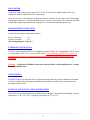
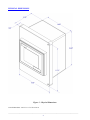
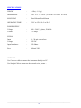
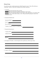
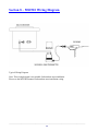
MS2510 Current Loop Receiver User Manual Metal Samples Company A Division of Alabama Specialty Products, Inc. 152 Metal Samples Rd., Munford, AL 36268 Phone: (256) 358-4202 Fax: (256) 358-4515 E-mail: [email protected] Internet: www.metalsamples.com . Table of Contents SECTION 1 – INTRODUCTION Receiving the Instrument................................................................................................................................................. 3 Unpacking ....................................................................................................................................................................... 3 Cleaning .......................................................................................................................................................................... 3 Installation ....................................................................................................................................................................... 3 Mounting ......................................................................................................................................................................... 4 Electrical ......................................................................................................................................................................... 5 Main Power ..................................................................................................................................................................... 6 Transmitter Connections ................................................................................................................................................. 6 Ethernet Connections ...................................................................................................................................................... 6 Adjustments..................................................................................................................................................................... 6 Storage and Installation Environment ............................................................................................................................. 6 Physical Dimensions ....................................................................................................................................................... 7 Specifications .................................................................................................................................................................. 8 SECTION 2 – SAFETY Potential Electrical Hazards ............................................................................................................................................ 9 SECTION 3 – START-UP AND OPERATION MS2510 Receiver Start-Up ................................................................................................................................. 11 Operation .......................................................................................................................................................... 12 Controls Operation ............................................................................................................................................. 14 Title Screen .................................................................................................................................................................... 14 Main Screen ................................................................................................................................................................... 15 Setup Screen ................................................................................................................................................................... 17 Data Chart Screen............................................................................................................................................................ 19 About Screen .................................................................................................................................................................. 20 SECTION 4 – MAINTENANCE Fuse Replacement ........................................................................................................................................................... 21 SECTION 5 – TROUBLESHOOTING Troubleshooting Procedures ............................................................................................................................................ 22 SECTION 6 – RETURNING THE INSTRUMENT FOR REPAIR Return Instructions ......................................................................................................................................................... 23 SECTION 7 – WARRANTY Warranty ......................................................................................................................................................................... 25 SECTION 8 – WIRING DIAGRAM Wiring Diagram .............................................................................................................................................................. 26 _______________________________________________________________________________________________ 2 . Section 1 - Introduction RECEIVING THE INSTRUMENT The MS2510 Receiver is carefully prepared for shipment to protect it during transit and to enable the user to install it with a minimum amount of reassembly. Upon receipt, the instrument should be carefully inspected for transit damage. If damage is apparent, notify Metal Samples and the carrier for claims inspection. UNPACKING Open the package and remove the instrument carefully. The instrument contains a display screen. While removing, utmost care should be given to the display. CLEANING Clean the instrument thoroughly to remove any foreign material that may have accumulated during shipment. INSTALLATION Place the receiver instrument in a convenient location, preferably away from heat producing sources or direct sunlight. Use the mounting brackets supplied with the instrument as shown in Figure 1. _______________________________________________________________________________________________ 3 MOUNTING Figure 1 – Instrument Mounting _______________________________________________________________________________________________ 4 ELECTRICAL Current Loop Fuse 100mA 250V Ethernet Port Transmitter Connections 1. Connect ‘+Ve’ terminal to TB1 2. Connect ‘–Ve’ terminal to TB2 Main Power Connection 1 Phase, 100 -240V AC, 50 /60 Hz, 2A Figure 2 – Connections _______________________________________________________________________________________________ 5 MAIN POWER Connect the single phase main voltage 100 V to 240 V by means of supplied main cord. Local regulations must be considered before connecting it. Note: In some cases, the instrument is shipped without a connector on the power cord. Each locality should inspect the power cord and install the proper connector if necessary. The connector should be installed in a properly grounded outlet for proper over current and earth fault protection. TRANSMITTER CONNECTIONS Connect the transmitter connections as below. Positive Terminal - 1 (+) Negative Terminal - 2 (-) (See wiring diagram – Page 26.) ETHERNET CONNECTIONS If you are connecting the MS2510 to an Ethernet switch or Router, use a Straight RJ45 cable. If you are connecting to a PC, use a Crossover RJ45 cable. Before connecting the MS2510 to your local network please contact your network administrator for proper IP address configuration of the instrument. Warning – A duplicated IP address may cause network failure at the installation site. Consult Network Administrator. ADJUSTMENTS The MS2510 Receiver functions must be adjusted and operated only by those authorized personnel who have read and who thoroughly understand the descriptions of the various control functions presented in this manual. STORAGE AND INSTALLATION ENVIRONMENT Protect the receiver instrument from mechanical stress, humidity, dust and thermal damage. Storage temperature is -20º C to +60º C. Operating temperature is 0o C to 50o C. _______________________________________________________________________________________________ 6 PHYSICAL DIMENSIONS Figure 3 – Physical Dimensions Overall Dimensions: 9.85” H x 11.73” W x 6.50” D _______________________________________________________________________________________________ 7 SPECIFICATIONS WEIGHT - ~4 lbs (~1.9 Kg) DIMENSIONS - 9.85” x 11.73” x 6.50” (25.02cm x 29.79cm x 16.51cm) MOUNTING - Panel Mount / Rack Mount OPERATING TEMP. - 32F to 122o F (0o C to 50o C) Voltage - 100 – 240 V, 1 phase, 50/60 Hz Current - < 2 Amps Input - 4 – 20 mA current loop Voltage - 24V DC Input Impedance - 250 Ohms Fuse - 100mA 250V POWER SUPPLY SIGNAL NETWORK Use Crossover cable to connect the instrument directly to a PC. Use Straight Cable to connect to the network switch, router… _______________________________________________________________________________________________ 8 Section 2 – Safety Always follow these warnings and safety procedures: Before attempting to operate or perform any service functions, all operators and service personnel should read this manual to become familiar with the complete operation of the instrument. Becoming familiar with all operating procedures will greatly reduce the possibility of accidents or injury. ONLY QUALIFIED OPERATORS AND MAINTENANCE PERSONNEL THAT HAVE COMPLETE AND CORRECT KNOWLEDGE OF THE RECEIVER INSTRUMENT SHOULD PERFORM ALL OPERATIONS AND MAINTENANCE PROCEDURES. POTENTIAL ELECTRICAL HAZARDS !!DANGER!! Do not touch electrically live components. Before performing any maintenance procedures, make sure that the main switch, located on the bottom of the instrument enclosure is in the “OFF” position. Receiver instrument must be properly grounded. Damaged electrical connections or wires should be replaced before power is applied. All covers must remain securely in place when power is applied or electrical shock may result. _______________________________________________________________________________________________ 9 Always follow these electrical system safety procedures: • Before servicing or troubleshooting procedures are performed, make sure that the electrical drawings for that area are up-to-date. • Follow proper plant, regional and national safety procedures while servicing the electrical systems on this instrument. • Remove all metal items, such as rings, metal necklaces and wrist watches. These are electrical hazards. Medical alert jewelry should be worn with caution. • Use insulated tools when working on electrical equipment to reduce the possibility of shock. • When troubleshooting with power activated, know the amount of voltage present in all areas before troubleshooting. • Before working on any circuit, check the circuit with the proper tester to determine if any voltage is present. • Be familiar with the proper handling of an electrical fire; keep carbon dioxide and dry powder fire extinguishers accessible at all times. • Always use fuses of a smaller capacity than the safe capacity of the line or equipment it serves. _______________________________________________________________________________________________ 10 Section 3 – Startup & Operation Warning - Ensure that the MS2510 receiver is connected properly. MS2510 RECEIVER START-UP If the MS2510 has not been used for an extended amount of time (overnight, weekend, or holiday), follow the procedure below to start the instrument: 1. Ensure the transmitter connections are connected properly to the MS2510 receiver unit. 2. Ensure the power cord is connected and power is turned on. The main switch is located under the instrument. The green light illuminates once the switch is on. 3. When the power is turned on, the instrument boots up and the Title screen appears for a short time. The display then changes to the Main screen which shows the metal loss and corrosion rate display. 4. After approximately a minute the display updates the current metal loss value. 5. Check the Probe life data on the Setup screen. If required, change the probe life according to the probe connected. Probe Initialization Message A Probe Initialization message will appear on the screen if the instrument loses the probe life data setting or if a new version of the program is installed. Pressing ‘OK’ on the message takes the display to the Setup screen. You may enter the right probe life using the pop-up keyboard on the screen. _______________________________________________________________________________________________ 11 OPERATION The MS2510 instrument is a line powered current loop receiver that provides 24V DC to power a 2 wire 4-20 mA instrument loop and provides a display of the loop value in metal loss and calculated corrosion rate. The corrosion rate time period can be set with different intervals of 48 hours, 7 days, 15 days and 30 days. The Corrosion rate is calculated using a simplified algorithm that calculates every 30 minutes based on the metal loss change over the previous 48 hours to 30 days according to the setting. The metal loss values are stored in the instrument’s internal memory with a time stamp. These values can be used for metal loss analysis at any given time. The built-in web server also can be used to monitor the display on a remote computer through a network. Output The Metal loss is calculated using one of the following formulas. Metal Loss (mils) = * ProbeLife Metal Loss (µm) = * ProbeLife * 25.4 Where: IL = Loop Current in mA ProbeLife = Usable portion of probe element thickness in mils (See Table 1.) _______________________________________________________________________________________________ 12 TABLE 1 : PROBE LIFE AND ELEMENT ID Element Type Wire Loop Tube Loop Strip Loop Cylindrical Spiral Loop Flush(Small) Flush (Large) Surface Strip Element Thickness Probe Life Element Identifier 40 mil 10 mil WR 40 80 mil 20 mil WR 80 4 mil 2 mil TU 04 8 mil 4 mil TU 08 4 mil 1 mil SL 04 8 mil 2 mil SL 08 10 mil 5 mil CT 10 20 mil 10 mil CT 20 50 mil 25 mil CT 50 10 mil 5 mil SP 10 20 mil 10 mil SP 20 4 mil 2 mil FS 04 8 mil 4 mil FS 08 20 mil 10 mil FS 20 10 mil 5 mil FL 10 20 mil 10 mil FL 20 40 mil 20 mil FL 40 10 mil 5 mil SS 10 20 mil 10 mil SS 20 40 mil 20 mil SS 40 _______________________________________________________________________________________________ 13 CONTROLS OPERATION TITLE SCREEN The Title screen is the first screen displayed when power is activated and after the instrument boots up. _______________________________________________________________________________________________ 14 MAIN SCREEN METAL LOSS Display indicates the active metal loss data in the selected unit (mils / microns). CORROSION RATE Display indicates the active Corrosion rate in the selected unit (mils / microns) per year. The corrosion rate is calculated based on the metal loss over the period of time which is set through the Setup screen. After the power is turned on the first time or after a probe is changed out, the corrosion rate will begin to calculate after 48 hours and will display a value at that time even if the instrument is set to a value other than the “48 hours” setting. If the set value is other than “48 hours”, once the set value time is reached, the instrument will start calculating the corrosion rate according to the set period. LIVE DATA This graph window displays the live data from the transmitter in metal loss value. _______________________________________________________________________________________________ 15 SETTINGS Press the Settings button to display the Setup screen DATA CHART Press the Chart button to view the Data Chart screen INFORMATION Press the Information button to display the About screen _______________________________________________________________________________________________ 16 SETUP SCREEN DISPLAY UNIT Press the ‘Display Unit’ button to change the display units of the metal loss and corrosion rate as mils or microns on the Main screen. CALCULATION PERIOD This selection unit is for calculating the corrosion rate per year based on the set time. This can be selected as 48 Hours, 7 Days, 15 Days or 30 Days. PROBE LIFE Set the Probe life according to the probe used on the field. This setting should be in mils. _______________________________________________________________________________________________ 17 HOME Press the Home button to display the Main screen MAINTENANCE Not Applicable. DATA CHART Press the Chart button to display the Data Chart screen INFORMATION Press the Information button to display the About screen _______________________________________________________________________________________________ 18 DATA CHART SCREEN YEAR Press the ‘Year’ entry box and enter the year for which the metal loss data should be charted. MONTH Select the month to view the metal loss data for the respective month or select ‘ALL’ to view the data for the whole year. HOME Press the Home button to display the Main screen _______________________________________________________________________________________________ 19 ABOUT SCREEN HOME Press the Home button to display the Main screen _______________________________________________________________________________________________ 20 Section 4 - Maintenance Fuse Replacement Replace the main fuse by following the procedure below. 1) Turn off the main Power switch 2) Remove the Single Phase power cord connected to the instrument. Fuse pull Tab 3) Using a small screwdriver or fuse drawer remover, push the tab shown in the above picture and pull the fuse drawer out. One spare fuse will be provided in the fuse drawer. Remove the blown fuse and replace with the spare. Press the fuse drawer inside and ensure it is properly locked in its position. 4) Connect the main cord and turn on the main power. _______________________________________________________________________________________________ 21 Section 5 – Troubleshooting Fault messages display on the status window to identify the location and type of fault that has occurred. This troubleshooting section addresses common instrument problems, possible causes and recommended solutions. IMPORTANT: It is not the intent of this manual to provide a highly detailed breakdown of all possible problems that may be encountered while using this instrument. Warning - If a problem cannot be easily corrected, contact Metal Samples for help. PROBLEM POSSIBLE CAUSE SOLUTION No Display Power is not activated. Check the main supply and ensure the switch in the “On” position. Blown Fuse Replace the fuse. Display defective Contact Metal Samples. Current loop wires loose Check and properly connect the current loop wires. Current loop wires polarity Check the polarity of the connected current loop wires. 24V missing Check 24V on current loop wires. Contact Metal Samples. No Metal Loss Value Display _______________________________________________________________________________________________ 22 Section 6 – Returning the Instrument for Repair If it is necessary to return any Metal Samples instrument for repair, the following procedure is recommended to ensure the fastest possible repair and return cycle. You may contact Metal Samples to verify that returning the instrument is necessary. 1. If possible, pack the instrument in the original shipping carton. If the original carton is not available, pack the instrument in a rigid cardboard or wood carton. Surround the instrument with a minimum of three inches of resilient packing material such as foam rubber or shredded newspaper. 2. Ship the instrument prepaid via air freight or air express to: Metal Samples 152 Metal Samples Rd. Munford, AL 36268 3. Contact Metal Samples by telephone (256) 358-4202, fax (256) 358-4515, or e-mail [email protected] and tell them: a. the name of the shipping company used for returning the instrument b. the estimated time of arrival c. the tracking number for the package 4. When the instrument is packed, include a copy of the form on the next page, filled in as required to expedite the repairs. _______________________________________________________________________________________________ 23 Return Form Use this form when returning instruments to Metal Samples for repair. Please fill in all known information. Enclose a copy of the completed form with the instrument. 1. Check one: Repair this instrument under warranty. Repair this instrument regardless of problem or cost of repair. Inspect the instrument and advise the customer of the approximate cost of repairs if the instrument is not covered under warranty. (Note: This procedure may delay the return of the instrument to you.) 2. Instrument Identification: Instrument Model #: Serial #: Date of Purchase: Company’s Purchase Order # for Original Sale: 3. Return the Instrument to: Company Name: Address/Location: Phone #: 4. Description of Trouble: (a clear description of the problem may shorten repair time). 6. Urgency of Repairs: _______________________________________________________________________________________________ 24 Section 7 – Warranty Metal Samples warrants that any part of their corrosion rate instruments and accessories which proves to be defective in material or workmanship within one year of the date of original shipment to Purchaser will be repaired or replaced, at the option of Metal Samples, free of charge. This warranty does not cover (1) probe assemblies, (2) items expendable in nature, or (3) items subject to damage from normal wear, misuse or abuse, or failure to follow use and care instructions. All damaged items are to be shipped at Purchaser’s expense to and from Metal Samples. Metal Samples shall have the right to final determination as to the existence and cause of the defect. The foregoing shall constitute the sole and exclusive remedy of any purchaser of Metal Samples products for breach of warranty and is exclusive and in lieu of all other warranties, expressed, implied or statutory, including the implied warranties or merchantability and fitness. In no event shall Metal Samples be liable for special or consequential damages or for any delay in the performance of this warranty due to causes beyond its control. Orders or requests for additional information should be addressed to: Metal Samples 152 Metal Samples Rd. Munford, AL 36268 Telephone: (256) 358-4202 Fax: (256) 358-4515 E-mail: [email protected] The technical information and suggestions contained herein are believed to be reliable, but they are not to be construed as warranties since conditions of use are beyond our control. _______________________________________________________________________________________________ 25 Section 8 – MS2510 Wiring Diagram Typical Wiring Diagram. Note: This wiring diagram is not suitable for hazardous area installation. Please see the MS2500E manual for hazardous area installation wiring. _______________________________________________________________________________________________ 26