1
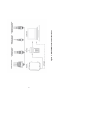
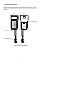
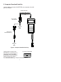
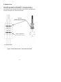
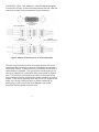
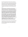
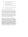
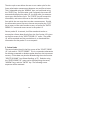
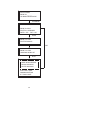
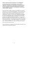
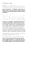
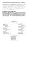
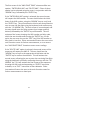
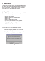
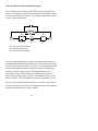
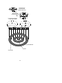
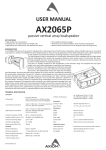
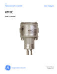
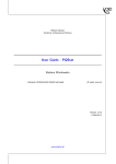
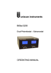
MS1500L
LPR Data Logger
Metal Samples Company
A Division of Alabama Specialty Products, Inc.
152 Metal Samples Rd., Munford, AL 36268
Phone: (256) 358-4202 Fax: (256) 358-4515
E-mail: [email protected] Internet: www.metalsamples.com
Table of Contents
I. Introduc on ..................................................................... 1
A. Instrument Func on Overview .................................. 1
B. Instrument Parts List .................................................. 4
C. Specifica ons ............................................................. 5
D. Ba ery Installa on ..................................................... 6
E. Computer Download Hook-Up ................................... 7
F. Adapter Use ............................................................... 8
II. Instrument Opera on .................................................... 10
A. Start-Up and Opera ons Overview .......................... 10
B. Select Probe I.D. ....................................................... 14
1. General ................................................................ 14
2. Enter New Probe .................................................. 15
3. Delete Probe ........................................................ 19
C. Make Measurement ................................................. 22
D. Recall readings ......................................................... 25
E. Delete readings ........................................................ 27
F. UNS Constant Table .................................................. 29
1. General ................................................................ 29
2. Addi on/Dele on of UNS Codes ......................... 30
G. Communica ons ...................................................... 32
III. Theory of Opera on ...................................................... 42
IV. Tes ng the MS1500L with the LPR Meter Prover .......... 52
V. Appendices .................................................................... 54
Appendix 1 - Deriva on of Alloy Constant..................... 54
Appendix 2 - Returning Instrument ............................... 62
Appendix 3 - Warranty................................................... 64
I. IntroducƟon
A. Instrument FuncƟon Overview
The MS1500L is a hand-held measurement and data collec on
device. It is lightweight, easily handled, and ba ery operated so
that it can be carried to any loca on where measurement or data
collec on is required.
The MS1500L has several measurement func ons:
•
•
•
•
•
3-Electrode Linear Polariza on (corrosion-rate)
2-Electrode Linear Polariza on (corrosion-rate)
“Pi ng Index”
Zero Resistance Ammetry
Electrode Poten al
This versa lity allows the unit to be used with all commercially
available corrosion-rate probes. Addi onally, it can be used with
all types of galvanic probes to measure bimetallic corrosion,
changes in the oxidizing power of the process fluid and, with
suitable electrode combina ons, crevice and pi ng a ack, as
well as stress corrosion cracking.
Using galvanic probes with an appropriate combina on of
corroding, redox, and reference electrodes, it is possible to
measure the corrosion poten al of a corroding electrode, or the
redox poten al of the process fluid, which provides a wide range
of informa on on such phenomena as ac ve/passive transi ons,
inhibitor film persistency, inhibitor mechanisms, cathodic
protec on criteria, as well as providing an alterna ve means to
measure the onset of pi ng a crevice a ack and conjoint ac on
failure phenomena (e.g., stress cracking).
1
All measurements made with the MS1500L may be stored in the
onboard memory that will hold as many as 3000 readings from
up to 100 individual probes. All stored data may be called to the
instrument screen and reviewed at any me. A backup ba ery
will hold all data stored in memory for up to 12 months, in event
of failure of the main instrument ba ery.
Data may be selec vely deleted from memory to accommodate
addi onal informa on, once the 3000 reading capacity is reached.
Alterna vely, informa on may be downloaded to a PC as a
comma-delimited ASCII file for import into any of the standard
data analysis (spreadsheet) program such as Microso Excel.
In addi on to its measurements func on, the MS1500L may
be used as a data collec on and transfer terminal for Metal
Samples’ MS3500L remote LPR data logger. In this capacity the
accumulated data from several MS3500L field-based units may be
locally downloaded to the portable MS1500L and transferred to a
PC for further analysis.
2
3
Figure 1 - MS1500L Measurement FuncƟons
B. Instrument Parts List
The MS1500L comprises the following items:
Part No.
M-7500-M
IN1500L-3
ET0352
IN1500-3
IN1500L-5
MS1500L
IN1500L-2
B-8400-B
Qty.
1
1
1
1
1
1
1
1
DescripƟon
Opera ons Manual
Meter Prover
Serial Port Cable
9-Pin Serial Port Adapter
6-Pin Cable to 5-Pin Probe Adapter
Instrument
Instrument Carrying Case
9-Volt Ba ery
The user should check, upon receipt, that the above accessories
are included with the MS1500L unit. Any shortage should be
reported immediately to:
Metal Samples Company
152 Metal Samples Rd.
Munford, AL 36268
Phone: (256) 358-4202
Fax: (256) 358-4515
E-mail: [email protected]
4
C. SpecificaƟons
Model
MS1500L - Handheld LPR Corrosion Data Logger (Ordering #IN1500L)
Physical Data
Instrument Weight:
Total Weight w/ Carrying Case
and Accessories:
Instrument Dimensions:
1.4 lb. (0.64 Kg)
5.26 lb. (2.39 Kg)
7.63”H x 4.15”W x 2.0”D
(19.38cm x 10.54cm x 5.08cm)
10”H x 11.75”W x 5.4”D
(25.40cm x 29.85cm x13.72cm)
32° to 122°F (0° to 50°C)
-4° to 158°F (-20° to 70°C)
Carrying Case Dimensions:
Opera ng Temperature:
Storage Temperature:
Performance Data
Measurement Type
Range
ResoluƟon
2-Electrode
0 to 200 mpy
0.01 mpy
3-Electrode
0 to 200 mpy
0.01 mpy
Galvanic
± 999 μA
1 μA
Poten al
± 999 mV
1 mV
Electrical Data
Power Requirements:
Maximum Probe Cable Distance:
Output Specifica ons:
One 9V Ba ery
6 (1.83 m)
RS-232 Output in CommaDelimited ASCII Text Format
Special Features
• Microprocessor-based electronics
• Data storage capacity of 3000 readings on 150 different probes, with
ba ery backup
• Menu-driven interface using a 12-key keypad and a 4-line LCD display
• Low-ba ery detec on
• Portable
Accessory Items
Carrying Case, 6’ Probe Cable (a ached), Meter Prover, 6 to 5-Pin
Adapter, Galvanic Adapter, Communica ons Cable and Connector,
Opera on Manual
5
D. BaƩery InstallaƟon
Open the ba ery compartment by removing the “slip-fit” cover
on the rear of the instrument (shown below) and insert one 9-volt
ba ery.
FRONT
BACK
"SLIP-FIT" BATTERY COVER
1 9V BATTERY
POWER SWITCH
PROBE CONNECTOR
Figure 2. BaƩery InstallaƟon
6
E. Computer Download Hook-Up
Use this cable to connect the MS1500L to a computer via serial
port or USB port.
COILED DATA CABLE
MS1500 SERIAL
PORT ADAPTER
TO
COMPUTER
SERIAL
PORT
SERIAL TO USB
ADAPTER (OPTIONAL)
TO
COMPUTER
USB
PORT
Figure 3. Computer Download Hook-Up
Use the port on top of the
Top View of MS1500L
MS1500L for connec ng to a
computer (with the cable
provided) or to the MS3500L
(with the Op -link cable.)
See CommunicaƟons (p. 32) for more informa on.
7
F. Adapter Use
The probe connector on the MS1500L is a six-pin, female,
MIL-SPEC (MS-3106F-14S-6S) fi ng. It is designed for direct
connec on to any standard electrochemical probe manufactured
by Metal Samples (see illustra on below).
MS1500L
PROBE CABLE CONNECTOR
PROBE CONNECTOR
2 ELECTRODE PROBE
Figure 4. ConvenƟonal Probe / Instrument ConnecƟon
8
The IN1500L-5 (6 to 5 pin adapter) is a special adapter designed
to mate with all two- or three-electrode probes that use a five-pin
connector instead of the conven onal six-pin connector.
IN1500L-5
6 TO 5 PIN ADAPTER
(SUPPLIED)
3 ELECTRODE PROBE
MS1500L
PROBE CABLE CONNECTOR
IN1500L-5
6 TO 5 PIN ADAPTER
2 ELECTRODE PROBE
Figure 5. Adapter ConnecƟon for 2- or 3-Electrode Probes
The user may, from me-to- me, encounter probes with a nonstandard probe connec on, especially if the probes are of a noncommercial variety. To account for this possibility, the IN1500L-4
cable adapter is available. This comprises a conven onal six-pin
connector, a ached to a cable with leads, terminated in alligator
clips. This allows for individual termina ons to be made to any
non-conven onal probe, provided the probe connector pin-out is
known. If the user is unfamiliar with the pin-out on any par cular
probe, this can be established prior to probe installa on by
performing a simple con nuity check between the probe
electrodes and the probe connector pins.
9
II. InstrumentaƟon OperaƟon
A. Start-Up and OperaƟons Overview
Having installed the ba ery, as discussed on page 6, the unit is
ready for opera on. The instrument may be ac vated, using the
toggle switch on the le side of the base of the instrument.
When switched on, the instrument will ini ally show the self-test
screen, display the free storage, then automa cally jump to instrument func ons as shown below:
Metal Samples
MS1500L V/X.X
SYSTEM TEST: XXXX
“SYSTEM TEST SCREEN”
AUTOMATIC
Metal Samples
MS1500L V/X.X
FREE STRORAGE: XXXX
“FREE STORAGE SCREEN”
AUTOMATIC
> SELECT PROBE I.D.
MAKE MEASUREMENT
RECALL READINGS
DELETE READINGS
“MAIN FUNCTION SCREEN”
UNS CONST. TABLE
COMMUNICATIONS
SET TIME & DATE
10
The ini al screen showing the system test will scroll the four digit
number un l it has counted all the free storage. The free storage
is then displayed on the second screen, which appears automa cally.
A new instrument should show a free storage of 3000. If a
number lower than 3000 is shown, the instrument contains
stored data from factory tes ng. Any such data should be
located through the “SELECT PROBE I.D.” func on and deleted
(see Select Probe I.D., p.14, and Delete Readings, p.27 ).
Once the free storage has been displayed, the screen moves
automa cally to the instrument func on screen. This screen
shows a series of cursor-selectable op ons that allow the user
to enter data, or perform some measurement or ac on.
Prior to any other ac on, the user should use the down arrow
on the keyboard to select “SET TIME AND DATE,” followed by the
enter key to access the func on sub-menu screens that have the
following sequence:
SET TIME & DATE
HH:MM DD/MM/YR
UP ARROW WHEN DONE
SET TIME & DATE
HH:MM DD/MM/YR
ENTER TO ACCEPT
11
Individual digits of the date and me can be set using the keyboard numbers. Once an individual group (e.g., hours) is set, the
up arrow will shi the user to the next group of digits to be set.
Once the year group digits are set, the up arrow will bring up a
confirma on screen, the command “enter” will set the me and
date as shown. An “exit” command will leave the me and date as
previously set. Whether the “enter” or “exit” command is applied,
the user will be returned to the func on screen automa cally. At
this point, the user may either re-enter the “SET TIME AND DATE”
submenu to enter the correct me and date or, if sa sfied with
the current me and date func on, proceed to other measurements or data input.
The instrument clock will run on backup ba ery should the main
ba ery fail so, once the me and date is originally entered, there
should not be reason to further reset this parameter. Should
the user decide for any reason to reset the me and date a er
the ini al se ng, the me con nuity of any stored data will be
disrupted and data will prove tedious to analyze subsequent to
the me change.
The purpose of the remaining menus displayed on the func on
screen is described in detail in subsequent sec ons of this manual.
However, the following gives a brief overview of these func ons,
and their use:
SELECT PROBE I.D.:
This allows a probe to be given a
unique reference number, a selected
measurement mode, an electrode
alloy iden fica on and, where
necessary, a measurement me cycle
and electrode area modifying factor.
MAKE MEASUREMENT: This instructs the instrument to make a
measurement, and save the resul ng
data.
RECALL READINGS:
This allows the stored data from any or
all probes to be called to the instrument
screen and reviewed.
12
DELETE READINGS:
This permits the dele on of redundant
or obsolete data from memory.
UNS CONSTANT TABLE: This permits the inser on of correc on
factors when the user employs electrodes
of nonstandard surface area.
COMMUNICATIONS:
This executes the download of data
from the MS1500L to a PC, for further
processing and analysis.
SET TIME AND DATE:
This allows the user to alter the se ng
of the instrument clock.
13
B. Select Probe I.D.
1. General
This func on menu is central to the whole opera on of the instrument. With the excep on of the “UNS CONSTANT TABLE” and the
“SET TIME AND DATE”, no func on menu can be used prior to the
selec on of a probe I.D. The menu allows you to iden fy a specific
probe with data already in memory, for which the user requires
to make addi onal measurements, review exis ng data stored for
that probe, or delete data for the probe selected. It also allows
the user to enter a new probe I.D., together with a requirement
measurement func on, alloy iden fica on, and me cycle (if
required).
The “SELECT PROBE I.D.” func on may be entered by selec ng this
op on on the main func on screen using the cursor, then pressing
the “ENTER” key. The ini al submenu screen will appear as shown
below:
ENTER NEW PROBE
DELETE PROBE
XXXX XXXXX XXXXXX
XXXX XXXXX XXXXXX
XXXX XXXXX XXXXXX
The screen lists op ons for entering a new probe, dele ng a probe
and also lists all iden es for probes with data already stored in
memory. Those probes already in use are listed as a four-digit I.D.
number, three to five le ers and digits describing the measurement
type, and single le er followed by five digits designa ng the UNS
alloy code (p. 57 lists the most common alloys and their UNS
codes).
If the user simply wishes to make a measurement, recall readings,
delete reading, or download data for an exis ng probe, the specific
probe is selected, using the cursor and arrow keys, followed by the
14
“ENTER” key. The probe is now selected, and the user will be
returned to the main func on screen to make a measurement,
recall readings, delete readings, or download data for the probe
selected.
2. Enter New Probe
Whenever a new probe loca on is to be monitored, the user will
need to enter a unique probe I.D. number, an instruc on as to
measurement type, and an alloy designa on code. To do this,
select “ENTER NEW PROBE” from the ini al screen of the submenu using the cursor and arrow key, and ac vate the op on with
the “ENTER” key. This will ini ate the following screen sequence:
15
The ini al screen allows the user to insert a probe I.D. of up to
four digits, using the keyboard numbers. When the appropriate
I.D. number is entered, which may be any digital sequence the
user cares to adopt, the “UP ARROW” key will transfer the user to
the next screen.
If the user has selected a probe I.D. already in use, the menu
will divert from the normal sequence, inform the user that the
selected I.D. is already in use, and ask if old probe readings are
to be deleted. Unless the user wishes to delete exis ng probe
readings, the “EXIT” key should be selected, which will return the
user to the main func on menu, allowing re-entry to the “SELECT
PROBE I.D.” menu, so that the user may select a probe I.D. that
is not in use. Should the user wish to delete readings already
stored under the selected probe I.D., “ENTER” should be selected,
exis ng probe readings will be deleted, and the probe I.D. will be
free for reuse.
Assuming a unique probe I.D. has been selected, or the user has
elected to delete exis ng data as described in the previous paragraph, a screen will be shown allowing entry of the UNS code for
alloy iden fica on. This will be a le er, followed by a five-digit
number.
For most measurement applica ons, the UNS code is merely used
as reference data. However, in the case of a 2-electrode, linear
polariza on measurement, the UNS number will trigger the use
of an alternate propor onality constant in the instrument’s calcula on of corrosion rates. (See UNS Constant Table, p.57.)
The ini al le er of the UNS constant is selected from the keyboard, and confirmed using the “ENTER” key. The subsequent
five digits are selected using the keyboard and confirmed using
the “UP ARROW” key. The screen will automa cally change to the
alloy constant screen or the measurement type screen.
16
If the UNS code entered for this par cular probe is already contained in “UNS CONST. TABLE”, the instrument will already have a
record of the alloy constant, and will pass directly to the measurement type screen, if not the instrument will automa cally pass to
the alloy constant screen. The alloy constant screen allows the
user to input a two-digit number from the keyboard. This will be
a number less than ten given to the first decimal place, using the
“UP ARROW” when complete to pass to the measurement type
screen.
The alloy constant is a correc on factor used to account for
varia on in electrode surface area when making a two-electrode
corrosion rate measurement. A look-up table for forty-five of
the commonest alloy constants is programmed into the MS1500L
and, should the user select one of these alloys, the instrument
will automa cally enter this constant without showing the alloy
constant screen. Addi onal alloy constants are automa cally
added to the look-up table as the user programs them through
the “SELECT PROBE I.D.” menu; alterna vely they can be added
directly to the look-up table through the “ALLOY CONST. TABLE”
menu (see UNS Constant Table, p. 57). The look-up table will
hold a maximum of fi y alloy constants together with their UNS
codes, so that the user may occasionally wish to delete alloy
constants and UNS codes to make room for more frequently used
designa ons; this is also accomplished through the
“ALLOY CONST. TABLE” menu. (A table of common UNS codes,
together with appropriate alloy constants is given on p.57).
The measurement type screen, which is shown automa cally a er
the UNS code screen or the alloy constant screen, allows the user
to select the measurement type by using the “ARROW” keys to
scroll, and the “ENTER” key to select. The measurement types
that are selectable are:
17
LPR3A:
3-electrode, linear polariza on (corrosion rate)
using anodic polarizing current.
LPR3C:
3-electrode, linear polariza on (corrosion rate)
using cathodic polarizing current.
LPR2:
2-electrode, linear polariza on (corrosion rate).
GALV.:
2-electrode, zero-resistance, current measurement.
POT.:
2-electrode poten al measurement.
Once the measurement type has been selected, one of two
screens will present itself to the user. If galvanic or poten al
measurement has been selected, a screen showing the probe I.D.
number, the UNS code, and measurement type will be shown. If
the informa on shown on the screen is consistent with the user’s
requirement, the “ENTER” key will accept this informa on and
return the user to the main func on menu from which actual
measurements may be made. Should the screen show incorrect
informa on, the user can use the “EXIT” key to return to the main
func on menu, from which the “ENTER PROBE I.D.” func on can
be re-accessed to correct the probe I.D. informa on.
If the user has selected either two or three-electrode linear
polariza on measurement, a me cycle screen will be shown
subsequent to the measurement type screen. Unlike galvanic or
poten al measurement, linear polariza on is not truly instantaneous. A period of me is required, following the imposi on of
the polarizing voltage, during which capaci ve discharge takes
place at the electrode prior to the establishment of an equilibrium polarizing current. If insufficient me is allowed for the
establishment of the equilibrium current, the resultant corrosion
rate measurement will be falsely high. The me required for the
establishment of equilibrium will vary from system to system.
18
The me cycle screen allows the user to set a me cycle for the
linear polariza on measurement between one and five minutes.
This is selectable using the “ARROW” keys, and confirmed using
the “ENTER” key. Once the me cycle is entered, the screen will
automa cally display the probe I.D., the UNS code, the measurement type, and the me cycle. The “ENTER” key will accept this
informa on, and return the user to the main func on screen,
from which the user may elect to make a measurement. Should
the informa on prove incorrect, the user may employ the “EXIT”
key to return to the main func on screen, re-access the “ENTER
PROBE I.D.” menu and correct errors in the probe I.D.
Once a probe I.D. is entered, it will be stored and can be reaccessed at a future date directly from the list of probe I.D.’s given
on the first screen of the “SELECT PROBE I.D.” menu. The probe
I.D. will be retained un l the user deletes it, or downloads the
informa on for that probe I.D. to a computer.
3. Delete Probe
The second op on listed in the first screen of the “SELECT PROBE
I.D.” sub-menu is “DELETE PROBE”. This is a convenient alterna ve
for dele ng unwanted or obsolete probe data from the instrument
memory. Probe data may also be deleted using the main func on
“DELETE READING” (see Delete Readings, p.27). Dele on using
the “ENTER PROBE I.D.” route can be selected using the cursor,
“ARROW” keys, and the “ENTER” key. The following screen
sequence will be ac vated:
19
DELETE PROBE
PROBE ID: _ _ _ _
UP ARROW WHEN DONE
UP ARROW
*** WARNING ***
PROBE ID: XXXX
DELETE ALL READINGS
ENTER = YES EXIT = NO
ENTER
PROBE ID: XXXX
DELETE READINGS
AUTO
PROBE ID: XXXX
UPDATING PROBE LIST
AUTO
> SELECT PROBE I.D.
MAKE MEASUREMENT
RECALL READINGS
DELETE READINGS
UNS CONST. TABLE
COMMUNICATIONS
SET TIME & DATE
20
EXIT
The user should scan the list of probe I.D.’s to iden fy and
memorize the probe I.D. to be deleted, since this will be
requested. If the probe I.D. in ques on is not known, the user
will have the tedious task of returning to the main func on
screen, scanning the probe I.D. list, and finally re-entering the
“DELETE PROBE” sequence.
Once the “DELETE PROBE” sequence is entered, the screen will
request the I.D. of the probe to be deleted. This is entered using
the numeral keys, and the “UP ARROW” key at the conclusion.
A warning screen will now appear lis ng the probe I.D. to be
deleted, and a request for confirma on. If the user is in doubt,
the “EXIT” key should be used, to return the user to the main
func on screen without dele on of any data. Having decided
that the probe data is of no further value, use the “ENTER” key to
delete the probe data. The instrument screen will now automa cally sequence through a “DELETING READINGS” screen followed
by an “UPDATING PROBE LIST” screen, and finally returning the
user to the main func on screen.
Once this sequence is complete, the probe data and probe I.D. are
removed from the MS1500L memory.
21
C. Make Measurement
Before any measurement can be made, a probe I.D. must be
selected. This may be done in one of two ways. If the probe is
one for which a probe I.D. and data are already stored in memory,
simply enter the “SELECT PROBE I.D.” submenu, scan the exis ng
probe I.D. lis ngs, and select the appropriate probe I.D. using the
cursor, “ARROW” keys, and the “ENTER” key when the cursor is set
on the required probe I.D. The probe is then selected, and the
user will be returned to the main func on menu, from which
the user may enter the “MAKE MEASUREMENT” submenu, to
measure the selected probe. Unless the instrument is switched
off, or a new probe I.D. selec on is made, the probe remains
selected, and any number of measurements may be made without re-selec on.
If the probe to be measured is a new probe without an I.D. in
memory, the user must enter a probe I.D. (see Enter New Probe,
p. 15). Upon comple on of the “ENTER NEW PROBE” sequence,
the user is automa cally returned to the main func on menu, the
new probe automa cally has been selected, and measurements
may be made by selec ng the “MAKE MEASUREMENT” submenu.
As with an exis ng probe, a new probe may be subjected to as
many measurement cycles as desired without re-selec on,
provided the instrument is not switched off.
Once a new, or exis ng, probe has been selected, the make
measurement sequence may be entered from the main func on
menu using the cursor, “ARROW” keys, and the “ENTER”
instruc on. This will ini ate the screen sequence shown on
the next page:
22
The first screen of the “MAKE MEASUREMENT” submenu displays
the probe ID, UNS code, and measurement type. If this is correct,
the user should use the enter key to start the measurement cycle.
If the probe ID is incorrect, the user should use the “EXIT” key to
return to the main menu and then enter the “SELECT PROBE I.D.”
submenu to select the correct probe I.D.
If the measurement type is galvanic or poten al, a er ini a on
with the enter key, the measurement will be completed in less
than fi een seconds. The screen showing the measurement value
will appear displaying either probe I.D. and current (expressed
milliamps to three decimal places), or the probe I.D. and potenal (expressed millivolts to one decimal place). Either screen will
instruct the user to use the “ENTER” key to save the measurement. If the user does not require to save the measurement, the
“EXIT” key can be used. Both the “ENTER” and the “EXIT” key will
return the user to the main func on menu allowing subsequent
measurements on the same probe or selec on of a new probe for
measurement.
23
If the measurement type is either two or three-electrode linear
polariza on, the “ENTER” will ini ate the measurement me cycle
as set by the user in the “SELECT PROBE ID” sequence. During the
measurement me cycle, the screen will display the probe I.D. and
the me cycle shown in whole minutes; a request to wait is also
displayed. During the measurement cycle, the minute indicator
will flash at one second intervals, and will count down whole
minutes to zero. Since the 2-electrode measurement involves
two polariza on cycles, one anodic and one cathodic, the actual
me cycle set by the user is half the total measurement me;
the user should ensure that the cycle set for a 2-electrode linear
polariza on measurement is half the desired total measurement
me.
At the conclusion of the linear polariza on measurement cycle,
the 3-electrode measurement will display the probe I.D. and
the corrosion rate in MPY (“MIL PER YEAR”). The two-electrode
measurement will also display the pi ng index. Either screen will
instruct the user to “PRESS ENTER TO SAVE”, which will save the
measurement and return the user to the main func on menu, to
make further measurements. The “EXIT” key will also return the
user to the main menu, but will not save the measurement.
24
D. Recall Readings
This main func on allows the user to recall all readings stored
under any probe I.D. to the instrument screen for review. As with
most func ons, the precursor to use is to select the probe of
interest. This is accomplished by entering the “SELECT PROBE ID”
submenu, reviewing the list of probe I.D.’s stored, and using the
cursor coupled with the “ENTER” instruc on to select the probe
and return to the main func on menu.
Once the probe I.D. is selected, the “RECALL READINGS” submenu
is entered using the main func on menu cursor, directed by
“ARROW” keys, and ac vated with the “ENTER” key. The following
screen sequence comprises the “RECALL READINGS” submenu.
The ini al screen of the “RECALL READINGS” submenu shows the
last reading number, date, and measurement type sequen ally
on the top line. The reading number is merely the total number
of readings stored, which is also the number of the most recent
reading stored. The date is shown in the European form of day/
month/year. The next line shows the measured value, which may
be millivolts, milliamps, or corrosion rate depending on the
measurement type. If the measurement type is 2-electrode linear
polariza on, a third line will show a dimensionless number, the
so-called pi ng index.
25
The last line is an instruc on to use either the “ARROW” keys
or the “ENTER” key. The “ARROW” keys allow the user to scroll
backwards (“DOWN ARROW”) and forwards (“UP ARROW”),
sequen ally, through the stored readings for the selected probe.
In instances where several hundred readings are stored, and the
user wishes to access a specific reading, use of “ARROW” keys and
scrolling can prove tedious. In such a case, the user should use
the “ENTER” key which will call up the reading number screen.
The user can insert the reading number of specific interest and
use the “UP ARROW” to recall the ini al screen at the reading
number selected; scrolling either side of the selected reading
number can be resumed using the “ARROW” keys. The user can,
at any me, return to the main func on menu using the “EXIT”
key.
26
E. Delete Readings
This func on is more selec ve than the “Delete Probe” func on
(p.19) found in the “SELECT PROBE I.D.” submenu. Using the
“Delete Readings” func on, it is possible to selec vely delete
individual readings stored under any given probe I.D.
Having selected a probe the user may select the “Delete Readings”
func on using the cursor and “ENTER” key on the main func on
screen. The following screen sequence illustrates the use of the
“Delete Readings” sub-menus:
The first screen of the sub-menu requires the user to insert the
reading number at which the dele on process should start. For
example, if the user wishes to delete the first 50 readings, the
number “1” will be the reading number at which dele on starts.
Once the appropriate number is entered, the ‘UP ARROW’ will
take the user to the new sub-menu screen.
27
This second screen displays the reading number at which deleon is to start, together with the date of this reading displayed in
European format. The screen also requests the process is to stop.
Once the number of the final reading to be deleted is entered, the
‘UP ARROW’ will then display an ac on confirma on screen.
This ac on confirma on screen shows the user both the ini al and
final ending number in the dele on sequence, together with the
date of each reading. If the user wishes to proceed with dele on,
the enter key is used and, a er a short wai ng period, the deleon is complete. At this point, the screen automa cally reverts
to the main func on screen and, the selected readings have been
deleted. Should the user not wish to proceed with dele on, the
user should press the “EXIT” key, returning automa cally to the
main func on screen without dele on of any readings.
28
F. UNS Constant Table
1. General
As explained in the “ENTER NEW PROBE” sec on, the UNS alloy
code is used exclusively for reference in the case of 3-electrode
linear polariza on measurement, galvanic measure-ments, and
poten al measurements. It merely allows the user, through the
probe I.D. lis ngs in the “SELECT PROBE ID” submenu, to have a
permanent record of the type of alloy used for the electrodes of a
specific probe.
The excep on to this func on is when the measurement type is
a 2-electrode linear polariza on measurement. In this case, the
UNS code will alter the constant of propor onality, used in the
corrosion rate calcula on. This is necessary since each alloy/
metal has a unique factor in the equa on rela ng polarizing current to corrosion rate. This factor is the equivalent weight divided
by the density. In conven onal 3-electrode measurements, this
uniqueness is accounted for by varying the surface area of the
working electrode from alloy to alloy to account for these variaons. Essen ally, the surface area of the working becomes part
of the instrument constant. However, the major manufacturer
of electrodes for the two-electrode linear polariza on measurement uses a constant electrode surface area, irrespec ve of
alloy. Consequently, when making a two-electrode polariza on
measurement, an addi onal factor must be incorporated into the
instrument constant to account for the variable density and equivalent weights. Precise deriva on of the “alloy constant” is shown
in Appendix 1 of this manual, as is a table of common alloys their
UNS code, and the appropriate alloy constant.
The “UNS CONST TABLE” contains a lis ng of 45 of the most
common alloys, which is used as a look-up table, automa cally
applying an appropriate alloy constant to each two-electrode
linear polariza on measurement. The “UNS CONST TABLE” funcon is accessible to the user through the main func on menu, to
allow addi ons or dele ons from the UNS/alloy constant table.
29
The table has a maximum capacity of fi y lis ngs. A empts to
add more than the total of fi y, either directly through the “UNS
CONST TABLE” or through the “SELECT PROBE ID” func on will
overwrite the ini al lis ngs in the table. To avoid elimina on of
regularly used alloy constants, the user should delete constants
and UNS codes that are rarely used before adding new ones,
once a total lis ng of fi y has been reached.
2. AddiƟon / DeleƟon of UNS Codes
Access to the “UNS CONST TABLE” func on is achieved, as with all
main func ons, by use of cursor “ARROW” keys, and “ENTER” key
in the main func on menu. Unlike most func ons, entry into the
“UNS CONST TABLE” does not have to be preceded by a probe I.D.
selec on. This submenu sequence for this func on is illustrated
below:
30
The first screen of the “UNS CONST TABLE” submenu offers two
op ons, “ENTER NEW UNS” and “DELETE UNS”. Either of these
op ons can be selected using the cursor in conjunc on with the
“ARROW” keys, followed by the “ENTER” key.
If the “ENTER NEW UNS” op on is selected, the second screen
will request the UNS number. The user should select the ini al
le er of the UNS number, using the “ARROW” keys to scroll, and
the “ENTER” key. This will ac vate the third screen that allows the
user to enter the five digits using the keyboard, and confirm entry
with the “UP ARROW” key. The forth screen is now ac vated, and
the user should enter the alloy constant (one integer and first
decimal) followed by the “ENTER” key confirma on. This will
ac vate a final screen showing the UNS number and alloy code,
which the user should confirm using the “ENTER” key. At this
point, the user may also use the “EXIT” key if the UNS number or
alloy code is incorrect. Either command will return the user to the
main func on screen for further measurements, or to re-access
the “UNS CONST TABLE” func on to enter correct codings.
If the “DELETE UNS” op on is selected, the second screen of the
sequence will request the UNS ID. The user should use the
“ARROW” key to scroll to the appropriate ini al le er and the
“ENTER” key to confirm the selec on. This will ac vate the
second screen, allowing the user to enter the remaining five digits
using the keyboard, and finally confirming the entry with the “UP
ARROW” key. This will ac vate the final screen of the sequence
showing the UNS code and reques ng an “ENTER” instruc on
to delete, or an “EXIT” instruc on to abort dele on. Either
instruc on will return the user to the main func on screen for
further measurements or data input.
31
G. CommunicaƟons
The MS1500L Data Logger has the ability to store readings as they
are taken. These readings can later be transferred to your PC via
serial port or USB port. To transfer data to a PC it is necessary to
install the Corrosion Data Management So ware.
Installing the SoŌware
To run the Corrosion Data Management So ware, you need a PC
that meets the following requirements:
•
•
•
•
•
•
•
•
Pen um® class processor
Windows® 95 or higher opera ng system
16 MB of RAM
10 MB of available hard-disk space
VGA monitor with 800 600 or greater resolu on
Mouse or poin ng device recommended
Available 9-pin serial port or USB port
CD-ROM drive for so ware installa on
To install the Corrosion Data Management So ware:
1. Insert the setup disk provided in your accessory kit.
2. You will be prompted to close any open programs. A er
you have done so, click OK to con nue.
32
3. Click the install bu on to begin installa on. Note, it is
recommended that you install the so ware in the default
directory.
4. A er clicking the install bu on, the so ware will be
installed on your PC.
5. When the so ware installa on is complete you should
remove the setup disk, then reboot your computer.
33
Instrument Download Center
The Instrument Download Center is a simple tool for retrieving
data from Metal Samples ER and LPR data logger instruments.
To download data from an instrument:
• Connect the instrument to an available PC serial port or
USB port (see page 3.)
• Turn the MS1500L on.
• Run the Corrosion Data Management So ware
• Open the Instrument Download Center
• Select the serial port and instrument
• Click the Download bu on (ensure that Part Status toggles
to “On”).
• From the main menu of the instrument, go to the Select
Probe I.D. menu and select the probe data you wish to
download.
• From the main menu of the instrument, go to the
Communica ons menu and select Computer Upload.
Data will begin to transfer from the instrument to the PC, and will
appear in the data window of the Instrument Download Center as
shown above. If the data appears garbled, the wrong instrument
type has been selected. Select another instrument type and try
again. If data does not appear in the data window at all, verify
that:
34
•
•
•
•
•
The instrument is connected to a valid serial or USB port
All cables are securely connected
The message “Port Status: On” appears in the status bar
There are no errors on the instrument
If using a USB adapter, ensure that the device drivers have
been installed.
SelecƟng a Serial Port
Use the Serial Port selec on box to select the port to which the
instrument is connected. If the COM port number is unknown, it
can be found in Windows Device Manager under “Ports (COM &
LPT)”.
SelecƟng an Instrument
Use the Instrument op on box to select the model of Metal
Samples instrument being downloaded. This sets the appropriate
communica on parameters, which will be displayed in the status
bar at the bo om of the window (“9600,N,8,1” for an MS1500,
“2400,N,8,1” for an MS3500).
Downloading Data
To toggle the selected port on and off, click the Download bu on.
Toggling the port on and off will also clear the data window.
Once a valid serial port and instrument have been selected, click
the Download bu on to turn the port on and enable the computer to receive data. If a valid serial port has been selected, the
status bar at the bo om of the window will display the message
“Port Status: On”. If an invalid serial port has been selected, an
error message will appear, and the status bar will display the message “Port Status: Off ”. If this happens, another serial port should
be selected.
35
Saving Data
To save the data in the data window, click the Save bu on. The
data is comma-delimited ASCII text. It can be saved to a standard
text (.txt) file, or it can be saved to a comma-separated values
(.csv) file, which greatly simplifies the process of impor ng the
data into a spreadsheet program such as Excel®.
PrinƟng Data
To print the contents of the data window, click the Print bu on.
A print dialog box will be displayed to allow printer selec on and
setup.
CharƟng Data
To chart the contents of the data window, click the Chart Data
bu on. If the data has not yet been saved, the user will be
prompted to do so before the char ng process begins. For more
informa on on char ng data, see the Data Analysis sec on.
Data Analysis
The Data Analysis u lity is a convenient tool for char ng data from
Metal Samples ER and LPR data logger instruments. The Data
Analysis u lity can be opened from the Main Menu, or it can be
opened directly from the Instrument Download Center.
If the Data Analysis u lity is opened from the Instrument Download Center, the contents of the data window will be loaded into
the chart. However, if the Data Analysis u lity is opened directly
from the Main Menu, a valid data file must be loaded. The Select
File box will open to allow selec on of a data file.
36
Loading a Data File
A er selec ng a data file (or clicking the Chart Data bu on from
the Instrument Download Center) a status window will display the
progress of the file being opened, along with the Instrument Type,
Probe Type, and Probe ID for the data file.
Data Table
A er a file has been successfully loaded, the data will be displayed
in the Data Table for review. By default, all data points will be
included in the chart. However, data points can be turned off,
or excluded, from the chart. If the “Excluded” flag appears in the
status column for a data point, that data point will not appear in
the chart. To toggle the exclude/include status of a data point,
double-click the data point, or select the data point and click
Exclude/Include in the OpƟons menu.
PrinƟng Data
The data table can be printed by clicking Print in the OpƟons
menu. A print dialog box will be displayed to allow printer
selec on and setup.
37
CreaƟng A Chart
To chart the selected data, click the Chart Data bu on, or select
Chart Data from the OpƟons menu. The chart will be displayed in
a new window.
PrinƟng a Chart
A chart can be printed using the Print Chart op on in the File
menu. A print dialog box will be displayed to allow printer selecon and setup.
ExporƟng a Chart
A chart can be exported to other applica ons using the Copy Chart
op on in the File menu. This will copy both the chart and the raw
data to the Windows® Clipboard. The chart can then be inserted
into other applica ons using the Paste func on. Note: In some
applica ons, using the Paste func on will insert the raw data
instead of the chart. In this case, use the Paste Special func on,
then select Picture to insert the chart.
Chart Tools
• StaƟsƟcal Data
The StaƟsƟcal Data tab at the bo om of the Data Chart
window will display a page with sta s cal informa on
about the chart data. If the Sta s cal Data page is visible,
this informa on can be printed by clicking Print StaƟsƟcal
Data in the File menu.
38
• Finding A Data Points Value
While viewing the chart, the value of any data point can
be determined by simply clicking it. The value will be
displayed in the charts tool- p box (a small text box that
is displayed near the mouse pointer). If the tool- p box
does not appear immediately a er clicking the data point,
hold the mouse pointer sta onary over the chart back
ground for a moment.
• The Tools Menu
The Tools menu contains a collec on of u li es for viewing
and manipula ng the chart. The Tools menu can be
accessed by clicking Tools on the menu bar, or by rightclicking anywhere on the chart.
○ Data Markers
Show Data Markers toggles the data markers on and off.
○ Mean Value
Show Mean Value toggles the mean value line on and off.
○ Trend Line
Show Trend Line toggles the trend line on and off.
39
○ Title/Footnote Setup
Title/Footnote Setup displays a window that allows the
chart tle and footnotes to be toggled on and off, and to
be modified.
○ Plot Setup
Plot Setup displays a window that allows configura on of
Y-axis scaling, and of the chart type.
The Y-axis can be scaled to default values by checking
the Auto Scaling op on box. The Y-axis can be scaled to
manual values by un-checking the Auto Scaling box, then
entering the desired values in the Minimum and Maximum
fields.
The chart type can be set to Line Chart, Bar Chart, or Area
Chart by selec ng the appropriate bu on in the Chart Type
box. The default chart type is Line Chart.
○ Data Series Color
Data Series Color displays a color selec on box, which
allows the user to select the brush color for the plot line.
The default color for the plot line is Blue.
○ Zoom In
Zoom In allows a region of the chart to be enlarged so
that it may be viewed in greater detail. To enlarge a region
of the chart, click on the two data points that define the
le and right boundaries of the region.
In zoom mode, the mouse pointer will change to a crosshair. When zoom mode ends, the mouse pointer will re
turn to its normal state.
To cancel zoom mode, click Cancel Zoom In from the Tools
menu, or simply press the Esc key.
40
○ Zoom Out
Zoom Out restores the ini al view of the chart, which dis
plays the full data set.
○ Calculate Corrosion Rate
If the chart contains ER data, the Calculate Corrosion Rate
op on will become available under the Tools menu. This
op on allows the corrosion rate to be calculated between
any two data points on the chart. To calculate the corrosion rate click Calculate Corrosion Rate, then click two data
points. The corrosion rate between those two data points
will be displayed.
In calculate mode, the mouse pointer will change to an
arrow/ques on mark. When calculate mode ends, the
mouse pointer will return to its normal state.
To cancel a calcula on, click Cancel Calculate from the
Tools menu, or simply press the Esc key.
41
III. Theory of OperaƟon
Overview of Linear PolarizaƟon
When a metal/alloy electrode is immersed in an electroly cally
conduc ng liquid of sufficient oxidizing power, it will corrode by
an electrochemical mechanism. This process involves two, simultaneous, complementary reac ons.
At anodic sites, metal will pass from the solid surface into the
adjacent solu on and, in so doing, leave a surplus of electrons at
the metal surface. The excess electrons will flow to nearby sites,
designated cathodic sites, at which they will be consumed by
oxidizing species from the corrosive liquid. A simple example,
of iron dissolving in acidic solu on, is illustrated below:
SOLID METAL
CORROSIVE SOLUTION
ANODIC
SITE
Icorr
Fe2+
2e-
CATHODIC
SITE
H+
H2
H+
Fe
Fe2++ 2e2H+ + 2eH2
42
This electron flow, or movement of electric charge, cons tutes
an electric current ICOR. Since the flow of electric current in such
a situa on can be equated to loss of metal mass, or volume, by
Faradays Laws, ICOR is a measure of corrosion rate. The rela onship
of ICOR to corrosion rate is shown in Equa on 1:
C=
ICOR
x t x E xD
F
A
d
................. (1)
C = corrosion rate (MPY)
ICOR = corrosion current (mA)
A = surface area of metal/alloy (cm2)
t = no. of second in 1 year (31,536,000)
F = Faraday’s constant (96,494 coulombs. (gm.equ)-1)
E = Equivalent weight of metal (gm.(g.equ.)-1)
d = density of metal (gm.cm-3)
D = conversion factor, cen meters to mils. (393.7)
Equa on 1 reduces to:
C=
ICOR
x E x 128.67
d
A
................ (2)
Since E and d are known for all metals, and A can be fixed, a
measurement of ICOR would allow corrosion rate to be determined.
Unfortunately, direct measurement of ICOR is not possible, since
anodic and cathodic sites on a metal surface are con nually
shi ing within a con nuously conduc ng surface.
Indirect measurement of ICOR is possible. This can be achieved by
applying a small poten al shi (ΔE) to a corroding metal surface,
and measuring the current (ΔI) required to maintain this poten al
displacement. The value ΔE/ΔI, commonly called the polariza on
resistance, is inversely propor onal to ICOR. This rela onship is
embodied in the Stern-Geary equa on:
43
................ (3)
Rp =
ba =
bc =
polariza on resistance (ohms)
anodic rate constant (mV. decade -1)
cathodic rate constant (mV. decade -1)
Rearrangement of equa on 3 gives:
................ (4)
Subs tu ng from 4 into 2:
................ (5)
Prac cal measurement instruments fix the polarizing voltage at
some small value, for which equa on 3 holds true. This is usually
10mV or 20mV.
The ra o (ba• | bc | ) / (ba + | bc |) is assumed to be constant.
Although this is not strictly true, changes in ba and bc are largely
canceled out in the ra o. Commercial instruments generally
absorb this ra o into and empirical “constant”, which cons tutes
the average constant of propor onality derived from a large
number of E/ I measurements made with corresponding weight
loss data.
Varia ons in E/d values are prac cally accounted for by variaons in the surface area of the test specimen, or by programming
commercial instruments with an “alloy constant” for each possible
E/d value; this la er process is explained in Appendix 1, as is the
deriva on of the equivalent weight of an alloy.
44
A final factor influencing any prac cal measurement, is the capaci ve effect that is produced by polarizing a metal surface. Upon
ini al applica on of the polarizing voltage (ΔE), the resul ng current flow (ΔI) is a combina on of the true polarizing current (ΔI),
and the charging current (ΔIc) used in charging the double-layer
“capacitor” at the metal/solu on interface. This capaci ve current discharges a er a finite me leaving only the residual polarizing current that is the true measured value. This effect is illustrated below:
The true value of the polarizing current is the equilibrium value
(ΔI), that is established a er a me interval Tc. This me lag will
vary, depending on the specific characteris cs of the metal/
environment system, between approximately 30 seconds and
several hours. Typically, system exhibi ng high corrosion rate with
li le film forma on have short me cycles (Tc), whereas low corrosion rate systems showing strong film forma on have longer me
cycles. Commercially available instruments provide a variable
measurement me cycle to account for this phenomenon. Since
the decay characteris c is asympto c, even systems with extreme
“capacita ve iner a” will closely approach equilibrium within 15
minutes.
45
Two-electrode Corrosion Rate Measurement
This technique is the simplest of all LPR corrosion rate measurements. This u lizes a sensor with two iden cal electrodes, made
from the metal/alloy of interest. The no onal, equivalent electric
circuit, is illustrated below:
RP
E
T
CE
Rs
I
RP
A
CE
RP = Polariza on Resistance
RS= Solu on Resistance
CE= Electrode Capacitance
20mV are applied between the test and auxiliary electrodes, for
the predetermined (user-selectable) me cycle, and the polarizing
current at the end of the cycle (IF) is stored. The applied poten al
is then automa cally reversed, and the equilibrium polarizing
current (IR) value is again stored. The average value of the
polarizing current in the forward and reverse polariza ons is
then automa cally used to calculate, and display corrosion rate,
directly as MPY. This manipula on is based on equa on 5, p.44.
Since no instrumental method is used to account for varia ons in
E/d from metal to metal, this is preprogrammed into the measurement by menu selec on of alloy constant.
46
An addi onal factor that is displayed is the, so called, pi ng index.
This is, in fact, the ra o of the forward and reverse polarizing
currents (IF/IR). Some manufacturers claim that this value gives
some indica on of the pi ng characteris cs of the system. Metal
Samples cau ons the user to interpret the “pi ng index” with
considerable skep cism. This value merely indicates some form
of asymmetry between the two electrodes, of which pi ng is
on manifesta on of many. Some other possible sources of
asymmetric polariza on are non-uniform flow characteris cs or
scale deposi on, small differences in electrode composi on or
presence of surface inclusions, and varia ons in electrode surface
roughness.
Although the two-electrode measurement is electronically simple,
and allows the use of compara vely small sensors, it does have a
serious limita on. No means is incorporated into this technique
to allow for solu on resistance errors. For solu ons of significant
resistance, the polarizing voltage ΔE is par ally “dropped” across
the solu on resistance RS. Consequently, the amount of polarizing
voltage used to measure the polariza on resistance is lower than
that an cipated. This can be quan fied as follows:
ΔE
=
ΔIRP
- ΔIRS ................................ (6)
In effect, the true corrosion rate is under estimated by a percentage
given by:
PERCENT ERROR = (1 - RS / RP) x 100
The “IR-Drop Error” in this technique is directly proportional to
solution resistance and to corrosion rate. It is difficult to set absolute limits on applicability, however, fluids with a solution resistance of more than 50-100Ω cm-1 are likely to produce unacceptable errors. The technique should be confined to such fluids such
as brines, sea-water, cooling waters, and electrolyte solutions with a
concentration of 0.1M and higher.
47
Three-electrode Corrosion Rate Measurement
The three-electrode method uses a true poten osta c circuit to
shi the poten al of a test electrode 10mV. from the corrosion poten al (open-circuit, “equilibrium” poten al). Such a circuit may
be no onally represented as shown below:
10 mV
E
V
Reference
Test
Auxiliary
A
(R)
(T)
(A)
I
When a measurement is made, the instrument will ini ally null
any residual poten al difference between the reference electrode
and the test electrode. A er which, current will flow from the
auxiliary electrode onto the test electrode. The flow of current,
between the auxiliary electrode and the test electrode, will increase un l the test electrode poten al is shi ed 10 mV with
respect to the reference electrode. The current (ΔI) required to
sustain the 10 mV poten al shi is used to compute RP, which in
turn is used to provide a direct read out of corrosion rate.
48
This technique does not require the individual programming of alloy constants to allow for varia ons in E/d from alloy to alloy. This
varia on is accounted for by varying the surface of electrodes in
direct propor on to E/d from alloy to alloy, so that compensa on
is automa c.
The major advantage of the three-electrode LPR technique is that
it considerably lowers the effect of solu on resistance errors. This
is achieved by measuring the polarizing voltage, as the poten al
shi of the working electrode rela ve to a reference electrode, in
a high impedance circuit. Negligible current flows in this poten al
measuring circuit and, IR-drop errors are virtually eliminated.
Some residual IR-drop error does occur in highly resis ve soluons, due to the spreading of the current field generated by
the flow of current between the test electrode and the auxiliary
electrode. Excessive current spread will cause the field to impinge
on the reference electrode, which will introduce an IR-drop error.
The extent of this error is largely a func on of electrode geometry
as illustrated on the next page.
As can be seen, the “field effect” error is greatest with a triangle
electrode configura on, less so with a linear electrode configuraon, and almost non-existent with a concentric ring arrangement.
An appropriate choice of electrode geometry, will allow measurements to be made in solu ons with resis vi es of 1000 - 2000
Ω.cm-1. While this technique is a significant improvement on the
two-electrode measurement, it will give erroneous informa on in
discon nuous electrolytes, and poorly conduc ng fluids such as
dis lled water. In these la er cases, as with gases, the user must
resort to electric resistance corrosion measurement sensors.
49
A
T
TRIANGULAR
ELECTRODE
CONFIGURATION
R
LINEAR
ELECTRODE
CONFIGURATION
R
T
A
FLUSH ELECTRODE
CONFIGURATION
REFERENCE
TEST
AUXILIARY
50
In making the three electrode LPR measurement, the MS1500L
uses a high impedance poten al measuring circuit. Advantage is
taken of this circuitry to provide the user with a means of directly
measuring both redox and corrosion poten als. The uses of such
informa on in corrosion diagnos cs are many and various, and
a full discussion of this topic is beyond the scope of this manual.
However, a few examples are given below, to provide the reader
with some insight into the versa lity of poten al measurements.
ApplicaƟon
Cathodic
Protec on
Criteria of Assessment
-850mV vs. Cu/CuSO4 or
Nega ve Swing of 200mV
Electrode System
Cu/CuSO4 or Ag/AgCl
Reference vs. Protected
Structure
Oxygen Ingress Posi ve Poten al Swing
Pla nized Niobium vs.
Ag/AgCl Reference
Ac ce-Passive Passiva on - Posi ve
Ag/AgCl Reference vs.
Transi ons
Poten al Swing Ac va on Alloy of Construc om
- Nega ve Poten al Swing
Pi ng
Rapid Poten al Transients Iden cal Electrodes of
with Time
the Construc onal Alloy
With an appropriate choice of electrode combina ons, poten al
measurements will provide extensive informa on on file formaon and breakdown, localized a ack, and indicate the presence of
the various oxidizing species necessary for corrosive a ack.
51
IV. TesƟng the MS1500L with the LPR
Meter Prover
An LPR Meter Prover is provided to allow rou ne checks of
the MS1500L instrument. The LPR Meter Prover simulates a
3-electrode LPR probe at a fixed value which is printed on the
Meter Prover label (as shown below.)
To test the MS1500L with the Meter Prover:
1) Enter a new Probe ID in the MS1500L menu
with the following se ngs:
• Probe ID:
Enter any ID number that
does not conflict with probe
ID’s in use.
• Probe Type: LPR3A
• UNS Number: G10100
• Cycle Time:
1 Minute
See “ENTER NEW PROBE” on page 15 of the
user’s manual for detailed instruc ons.
Note: This Probe ID can be used for future
checks with the Meter Prover.
2) Connect the LPR Meter Prover to the MS1500L
probe connector as shown to the right.
3) Perform a measurement by selec ng “MAKE MEASUREMENT”
from the main menu (see page 22 of the user’s manual.)
52
4) Allow the measurement to finish. The measured value should
match the value on the Meter Prover label, and should be
within the printed tolerance. If the reading is out of tolerance
then further troubleshoo ng may be required.
It is important to remember that the LPR Meter Prover simulates
a 3-electrode probe. If the 2-electrode se ng is used to measure
the Meter Prover, the results will not match the printed value.
53
V. Appendices
Appendix 1 - DerivaƟon of Alloy Constant
The varia on of the Stern Geary equa on, rela ng the corrosion
current icor, to the polariza on resistance ΔE/ΔI is given by:
icor
=
ΔI BaBc
2.3 ΔE (Ba+Bc)
.......... (1)
which reduces to:
icor
icor
ΔE
ΔI
Ba+Bc
K
=
=
=
=
=
= K ΔI ............................... (2)
current due to corrosion (amps)
applied polarizing voltage (volts)
measured polarizing current (amps)
rate constants (volts/decade)
constant (dimensionless)
To convert the polarizing current to the conven onal MPY
(“MILS PER YEAR”) units of corrosion, Faraday’s laws are applied
as follows:
C =
icor x S
x
AxF
E
1000
x
d
254
...................... (3)
=
ΔI.k x S
x
AxF
E
1000
x
d
254
...................... (4)
=
S
F
A
E
d
C
ΔIk
A
x
=
=
=
=
=
=
E
x 128,668.6 ...................... (5)
d
number of seconds in one year
Faraday’s constant (coulombs)
working electrode surface area in cm2
equivalent weight of corroding metal (gms)
density of corroding metal (gms. cm-3)
corrosion rate (mpy)
54
Consequently, when the instrument calculates the corrosion rate
(mpy) from the measured polarizing current (ΔI), a means needs
to be found whereby the instrument can “know” the appropriate
value of E/d, and perform the correct calcula on of corrosion rate.
This is achieved in the conven onal, three-electrode LPR measurement by varying the surface area of working electrode in proporon to the E/d value of the metal/alloy in ques on, thus avoiding
the need to program special correc on factors into the instrument
for each and every alloy.
Unfortunately, the major producer of the two-electrode probe
uses a constant surface area for the working electrode, irrespecve of the metal/alloy under examina on. Thus a correc on
factor has to be applied for each metal/alloy under considera on.
This is, in fact, the alloy constant used for two-electrode corrosion
rate measurements in the MS1500L unit. The basic formula for
deriva on of the correc on factor is:
Ak =
0.55 x E
d
............................ 6
Ak = alloy constant
E = equivalent weight of metal/alloy in ques on (gms)
d = density of alloy in ques on (gms. cm-3)
For pure metals, if the appropriate alloy constant does not appear
in the MS1500L memory already, the user can apply equa on 6
to calculate, and program, the appropriate alloy constant into the
instrument memory.
Difficul es arise when trying to work out the equivalent weight of
alloys. This is approached by use of a weighted average, assuming all major metallic cons tuents corrode in propor on to their
weight percent for the alloy in ques on.
55
In general, metallic cons tuents present in amounts smaller than
1% are disregarded for the purposes of this calcula on. An example of this is given below for AISI 302 Stainless Steel.
Element
Chromium
Percent
18
Eq. Wt.
17.34
Eq. Wt. x Percent
3.12
Nickel
9
29.35
2.64
Iron
73
27.92
20.39
Alloy Eq. Weight
=
56
26.15
UNS Constant Table
The following lists many of the common construc onal metals/
alloys with their appropriate alloy constants. All of these values
are already programmed into the MS1500L memory. Addi onal
alloy constants can be added by the user, applying the calcula on
principles outlined previously, and with reference to the Table of
Equivalent Weights on p. 59.
UNS#
F12101
F13502
G10100
G10180
G10200
K03504
K03006
K02504
K03011
K01800
G41300
K41545
S50400
S30400
S30403
S31600
S31603
S32100
S41000
S43000
Alloy
Const.
1.0
1.0
1.0
1.0
1.0
1.0
1.0
1.0
1.0
1.0
1.0
1.0
1.0
1.0
1.0
1.0
1.0
1.0
1.0
1.0
Alternate
DesignaƟon
AISI 1010
AISI 1018
AISI 1020
ASTM A105
ASTM A106
ASTM A53
ASTM A350LF2
ASTM A516
AISI 4130
ASTM A199
ASTM A199 (T9)
AISI 304
AISI 304L
AISI 316
AISI 316L
AISI 321
AISI 410
AISI 430
57
Major ConsƟtuents
(or common names)
Gray Cast Iron
Gray Cast Iron
0.1% Carbon Steel
0.18% Carbon Steel
0.20% Carbon Steel
0.35% Carbon Steel
0.3% Carbon Steel
0.25% Carbon Steel
0.3% Carbon Steel
0.18% Carbon Steel
1% Cr 0.2% Mo Steel
5% Cr 0.5% Mo. Steel
9% Cr 1.0% Mo. Steel
18% Cr 8% Ni S.S.
18% Cr 8% Ni (Low Carbon) S.S.
18/Cr 10/Ni/ 3/Mo S.S.
“ (Low Carbon) S.S.
Ti Stabilized 18/8 S.S.
12% Cr. S.S.
17% Cr. S.S.
UNS#
S31200
S31803
C11000
C26000
C28000
C23000
C63000
C68700
C44300
C70690
C71590
N04400
N08825
N06600
N06625
N10001
N10002
N10276
N02201
N08904
Z13001
R05200
R50250
R60701
A96061
Alloy
Const.
1.0
1.0
2.0
1.8
1.8
1.9
1.9
1.9
1.8
1.9
1.6
1.2
1.0
1.0
1.0
1.0
1.0
1.0
0.9
1.0
1.3
0.6
0.7
1.0
0.9
Alternate
DesignaƟon
ASTM A182
ASTM A276
AMS 4500
AMS 4505
ASME SB111
ASME B16.22
AMS 4640
ASME SB111
ASME B111
ASTM F96
ASTM F96
AMS 4544
ASME B163
AMS 5540
AMS 5401
AMS 5396
AMS 5388
ASME B366
AMS 5553
ASME B625
ASTM B6
ASTM B364/365
ASTM F67
ASTM B493
AA6061
58
Major ConsƟtuents
(or common names)
26 Cr 6 Ni Duplex SS
22 Cr 5 Ni 3 Mo. Duplex S.S.
99.90 Copper
70-30 Brass
Muntz Metal (60% Cu)
85-15 Brass
Aluminum Bronze
Aluminum Brass (Arsenical)
Admiralty Brass
90-10 Copper Nickel
70-30 Copper Nickel
Monel 400
Incoloy 825
Inconel 600
Inconel 625
Hastelloy B
Hastelloy C
Hastelloy C-276
Nickel 201
23-1-4-25 Cr-Cu-Mo-Ni
99.990 Zinc
Tantalum
Titanium
Zirconium
Aluminum
Table of Equivalent Weights
Name
Symbol Atomic Wt.
Ac nium
Ac
(227)
Aluminum
Al
26.98
Americium
Am
243
An mony
Sb
121.76
Arsenic
As
74.92
Barium
Ba
137.36
Berkelium
Bk
(247)
Beryllium
Be
9.013
Bismuth
Bi
208.99
Cadmium
Cd
112.41
Calcium
Ca
40.08
Cerium
Ce
140.13
Cesium
Cs
132.91
Chromium
Cr
52.01
Cobalt
Co
58.94
Columbium, See Niobium
Copper
Cu
63.54
Curium
Cm
(247)
Dysprosium Dy
162.51
Erbium
Er
167.27
Europium
Eu
152.0
Francium
Fr
223
59
Valence
Equivalent Wt.
3
8.99
3
3
2
40.58
24.97
68.68
2
3
2
2
3
1
3
2
4.51
69.66
56.20
20.04
46.71
132.91
17.34
29.47
1
3
3
3
2
1
63.54
82.33
54.17
55.75
76.0
223
Table of Equivalent Weights (conƟnued)
Name
Symbol Atomic Wt.
Gadolinium Gd
157.26
Gallium
Ga
69.72
Germanium Ge
72.60
Gold, Arum Au
197.0
Hafnium
Hf
178.50
Holmium
Ho
164.94
Indium
In
114.82
Iridium
Ir
192.2
Iron
Fe
55.85
Lanthanum La
138.92
Lead,
Plumbum
Pb
207.21
Lithium
Li
6.94
Lute um
Lu
174.99
Magnesium Mg
24.32
Manganese Mn
54.94
Mercury
Hg
200.61
Molybdenum Mo
95.95
Neodymium Nd
144.27
Neptunium Np
(237)
Nickel
Ni
58.71
Niobium
(Columbium) Nb
92.91
Osmium
Os
190.2
Palladium
Pd
106.4
Pla num
Pt
195.09
Plutonium
Pu
(244)
Potassium
K
39.1
60
Valence
3
2
4
3
4
3
3
3
2
3
Equivalent Wt.
52.42
34.85
18.15
65.66
44.62
54.98
38.27
64.06
27.92
46.30
2
1
3
2
2
1
2
3
5
2
103.6
6.94
58.33
12.16
27.47
200.6
47.97
48.09
47.40
29.35
5
8
2
2
5
1
18.58
23.77
53.2
97.55
48.80
39.1
Table of Equivalent Weights (conƟnued)
Name
Symbol Atomic Wt.
Praserodymium Pr
140.92
Promethium Pm
(145)
Radium
Ra
226
Rhenium
Re
186.22
Rhodium
Rh
102.91
Rubidium
Rb
85.48
Ruthenium
Ru
101.1
Samarium
Sm
150.35
Scandium
Sc
44.96
Selenium
Se
78.96
Silver
Ag
107.87
Sodium
Na
22.99
Stron um
Sr
87.23
Tantalum
Ta
180.95
Techne um Tc
(97)
Tellurium
Te
127.61
Terbium
Tb
158.93
Thallium
Tl
204.39
Thorium
Th
(232)
Thulium
Tm
168.94
Tin, Stannum Sn
118.70
Titanium
Ti
47.90
Tungsten
W
183.86
Uranium
U
238.07
Vanadium
V
50.95
Y erbium
Yb
173.04
61
Valence
3
3
2
4
3
1
3
2
3
1
1
2
5
6
3
3
1
4
3
2
4
4
4
2
2
Equivalent Wt.
46.97
48.33
113
46.55
34.30
85.48
33.7
75.17
14.98
107.9
22.99
43.81
36.19
16.16
42.53
52.97
204.39
58.0
56.31
59.35
11.97
45.96
59.51
25.47
86.52
Appendix 2 - Returning an Instrument for Repair
If it is necessary to return any Metal Samples instrument for
repair, the following procedure is recommended to ensure the
fastest possible repair and return cycle. You may contact Metal
Samples to verify that returning the instrument is necessary.
1. If possible, pack the instrument in the original shipping
carton. If the original carton is not available, pack the
instrument in a rigid cardboard or wood carton. Sur
round the instrument with a minimum of three inches
of resilient packing material such as foam rubber or
shredded newspaper.
2. Ship the instrument prepaid via air freight or air
express to:
Metal Samples
152 Metal Samples Rd
Munford, AL 36268
Phone: (256) 358-4202
Fax: (256) 358-4515
E-mail: [email protected]
3. When the instrument is packed, include a copy of the
form on the next page, filled in as required to expedite
the repairs.
62
Copy this form when you need to return an instrument. Send a
copy of this form filled in as completely as possible.
1. Check one:
Repair this instrument under warranty.
Repair this instrument regardless of problem or cost of
repair.
Inspect this instrument and advise customer of
approximate cost of repairs if instrument is not covered
under warranty.
(Note: This may delay return of instrument to customer.)
2. Instrument Model #:
Serial #:
Date of purchase:
Customer’s original purchase order #:
3. Return this instrument to:
Company:
City/State/Zip:
Telephone:
E-mail:
4. Describe problem fully - this may shorten repair me.
5. Urgency of repairs:
63
Appendix 3 - Warranty
Metal Samples warrants that any part of Metal Samples corrosion
rate instruments and accessories which proves to be defec ve in
material or workmanship within one year of the date of original
shipment to Purchaser will be repaired or replaced, at the op on
of Metal Samples, free of charge. This warranty does not cover
(1) probe assemblies, (2) items expendable in nature, or (3) items
subject to damage from normal wear, misuse or abuse, or failure
to follow use and care instruc ons.
All damaged items are to be shipped at Purchaser’s expense to
and from Metal Samples. Metal Samples shall have the right to
final determina on as to the existence and cause of the defect.
The foregoing shall cons tute the sole and exclusive remedy of
any purchaser of Metal Samples products for breach of warranty
and is exclusive and in lieu of all other warran es, expressed,
implied or statutory, including the implied warran es or
merchantability and fitness. In no event shall Metal Samples be
liable for special or consequen al damages or for any delay in the
performance of this warranty due to causes beyond its control.
Orders or requests for addi onal informa on should be addressed
to:
Metal Samples
152 Metal Samples Rd
Munford, AL 36268
Phone: (256) 358-4202
Fax: (256) 358-4515
E-mail: [email protected]
The technical informa on and sugges ons contained herein are
believed to be reliable, but they are not to be construed as warran es since condi ons of use are beyond our control.
64