1
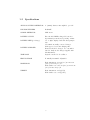
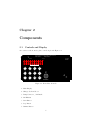
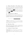
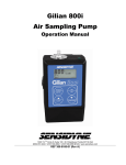
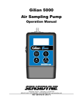
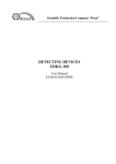
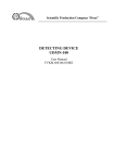
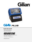
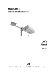
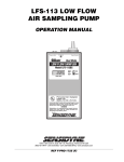
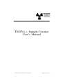
TM372++ Sample Counter
User’s Manual
Environmental Instruments Canada Inc.
http://www.eic.nu
Contents
1 Overview of Device
1.1 Introduction . . . . . . . . . . . . . . . . . . . . . . . . . . . . . . . .
1.2 Specifications . . . . . . . . . . . . . . . . . . . . . . . . . . . . . . .
2
2
3
2 Components
2.1 Controls and Display
2.2 Sample Tray . . . . .
2.3 Sample Holders . . .
2.4 Display Overview . .
2.5 Batteries . . . . . . .
.
.
.
.
.
.
.
.
.
.
.
.
.
.
.
.
.
.
.
.
.
.
.
.
.
.
.
.
.
.
.
.
.
.
.
.
.
.
.
.
.
.
.
.
.
.
.
.
.
.
.
.
.
.
.
.
.
.
.
.
.
.
.
.
.
.
.
.
.
.
4
4
5
6
6
7
3 Operation
3.1 Inserting the Sample . . . . . . . . . . . . . .
3.2 Timer Mode . . . . . . . . . . . . . . . . . . .
3.3 Pump Mode . . . . . . . . . . . . . . . . . . .
3.4 Gamma Mode . . . . . . . . . . . . . . . . . .
3.5 Performing an Automatic Rolle Sequence . .
3.6 Adding a Delay Before a Three Minute Count
3.7 Calculating Detector Efficiency . . . . . . . .
3.8 Daily Source Check . . . . . . . . . . . . . . .
3.9 Counting an Unknown Sample . . . . . . . .
3.10 Calibrating the Air Pump . . . . . . . . . . .
3.11 Resetting the Device . . . . . . . . . . . . . .
.
.
.
.
.
.
.
.
.
.
.
.
.
.
.
.
.
.
.
.
.
.
.
.
.
.
.
.
.
.
.
.
.
.
.
.
.
.
.
.
.
.
.
.
.
.
.
.
.
.
.
.
.
.
.
.
.
.
.
.
.
.
.
.
.
.
.
.
.
.
.
.
.
.
.
.
.
.
.
.
.
.
.
.
.
.
.
.
.
.
.
.
.
.
.
.
.
.
.
.
.
.
.
.
.
.
.
.
.
.
.
.
.
.
.
.
.
.
.
.
.
.
.
.
.
.
.
.
.
.
.
.
.
.
.
.
.
.
.
.
.
.
.
9
9
9
10
11
12
13
13
13
13
14
14
.
.
.
.
.
.
.
.
.
.
.
.
.
.
.
.
.
.
.
.
.
.
.
.
.
.
.
.
.
.
.
.
.
.
.
.
.
.
.
.
.
.
.
.
.
.
.
.
.
.
.
.
.
.
.
.
.
.
.
.
.
.
.
.
.
4 Detector
15
4.1 Internal Detector . . . . . . . . . . . . . . . . . . . . . . . . . . . . . 15
5 Reference
16
5.1 Reference . . . . . . . . . . . . . . . . . . . . . . . . . . . . . . . . . 16
1
Chapter 1
Overview of Device
1.1
Introduction
The TM372++ is both an ALPHA and GAMMA counter equipped with both a
foil type open zinc sulphide detector and Geiger counter. The foil type detector
is inexpensive, readily obtainable and is easily replaced. The alpha particles are
measured by using a photomultiplier tube to count the number of scintillations
caused by alpha particles striking the zinc sulphide. The gamma rays are detected
using a Geiger-Muller tube.
A sample tray opens near the bottom of the instrument into which a sample
holder may be placed. The sample holders can accommodate membrane filter
samples of 25mm, 37mm, or 47mm diameter.
The following sections describe the device itself as well as the procedures required to determine detector efficiency and measure the activity of a sample.
2
1.2
Specifications
ALPHA COUNTING DETECTOR
2” (50mm) diameter zinc sulphide open foil.
PHOTOMULTIPLIER
B38B01W
GAMMA DETECTOR
LND 71322
BATTERY SUPPLY
Five size AA NiMH rechargeable batteries.
Aproximately 15-20 hours, depending on number of digits displayed and time that pump is
run.
BATTERY LIFE (per charge)
BATTERY CHARGER
9V 660mA externally connected charger,
CSA approved. 16 hours charging time.
Batteries should be charged once a month if
left idle. Only use the charger supplied with
this instrument.
TIME BASE
Crystal controlled clock oscillator.
HIGH VOLTAGE
Nominally 450-1000V. Adjustable.
DIMENSIONS
Basic instrument: 21.6 cm (8.5”)w x 10.8 cm
(4.25”)d x 19 cm (7.5”) h
With leather case: 24.8 cm (9.75”)w x 11.4 cm
(4.5”)d x 20.3 cm (8”) h
WEIGHT
Basic instrument: 2.2 kg(5 lbs)
With leather case: 3.2 kg(7 lbs)
3
Chapter 2
Components
2.1
Controls and Display
An overview of the front face plate controls is given in Figure 2.1.
Environmental Instrum ents Canada Inc. http:/ /www.eic.nu
Sample Counter
Model TM372++
1
3
HV ON
DETECT
CHARGING / LOW BA TTERY
START
1
STOP
2
F
3
GAMMA
4
F
5
F
6
F
7
F
8
TOGGLE
9
PUMP
0
TIMER
ON/OFF
2
4
CHARGER
Figure 2.1: Front Plate Controls
1. Main Display
2. Charger Jack and Cover
3. Pump Connector / Air Intake
4. Air Exhaust
5. Start Button
6. Stop Button
7. Gamma Button
4
8. F8 Pump Flow Rate Button
9. Toggle Button
10. Pump Button
11. Timer Button
12. On/Off Button
Main Display: A five digit L.E.D. display where the alpha counts, gamma counts,
or a time is displayed. An overview is given in section 2.4
Charger Jack and Cover: The TM372++ runs off of internal rechargeable batteries. The batteries may be recharged by connecting the supplied charger to
this jack. See section 2.5 for more information.
Pump Connector / Air Intake: The open faced filter holder should be connected to this when collecting samples with the pump. When calibrating the
pump, the calibration device should be connected to this port.
Air Exhaust: The exhaust air from the pump exits through here.
Start Button: This button starts the alpha count, gamma count, or the pump.
Stop Button: Stops the count or pump.
Gamma Button: Used to enter/exit Gamma mode.
F8 Pump Flow Rate Button: Once a time has been entered for which the pump
will run, this button can be used to enter a desired flow rate for the pump.
Toggle Button: In Timer mode this button is used to briefly toggle the display to
show either the pre-set time that the user has entered or the elapsed time on
the count, depending on whether or not the device is counting at the moment
the button is pressed. In Gamma mode it is used to toggle between a short
and a long gamma reading average. It is also used to enter a mode in which
a rolle sequence can be automatically performed.
Pump Button: Used to enter Pump mode.
Timer Button: Used to enter a time for which the TM372++ will count or accept
a flow rate.
On/Off Button: Turns the device on or off. NOTE: This button must be held
for two seconds in order to turn the power off.
2.2
Sample Tray
The sample tray is located on the back of the device near the bottom. The sample
is held in the sample holder, which drops into the recess in the sample tray. To
count a sample, withdraw the tray, insert the sample as outlined in section 3.1,
close the tray, and start the counting cycle as described in section 3.2.
5
2.3
Sample Holders
Three 2 part sample holders are supplied with the TM372++ for membrane filter
samples of 25 mm, 37 mm, and 47 mm diameter. Alpha emitting calibration sources
are calibrated for either 2π or 4π geometry, and the active diameter is usually less
than the diameter of the disc.
When the membrane filter sample is inserted in the 2 piece holder assembly
it is secured around the edge, masking a portion of the filter from alpha particle
activity. The region that is masked is a ring of about 1 mm thickness around the
outside edge of the sample. This means, for example, that the active area of a 25
mm diameter sample would be the area within a 23 mm diameter. This, however,
will not adversely affect the activity reading because the outer edge is essentially
inactive.
2.4
Display Overview
The display consist of five 7-segment digits and nine indicator LEDs. The following
figure gives a summary of what each of the LEDs indicate. Each indicator will be
described in more detail in the following sections.
Counting
Detect Decaying/Colon 2 Minute Average
Gamma Reading
HV
Gamma Mode
Batteries
Batteries/
Batteries/
Decimal/Colon Decimal
Figure 2.2: A summary of indicator LED functions
While counting in Timer mode, a value will be displayed using either five digits
or three digits and an exponent. For numbers less than 100 000, five digits are used;
see Figure 2.3. For numbers greater than 99 999, three digits and an exponent are
used; see Figure 2.4.
Figure 2.3: An example of the display reading 19864
6
Figure 2.4: An example of the display reading 123 × 104
When the device detects either an alpha particle or a gamma ray, an LED at
the top of the display will briefly illuminate to show that it has registered a count,
as shown in Figure 2.5.
Figure 2.5: Registering a Count
2.5
Batteries
The instrument is equipped with 5 size AA NiMH rechargeable batteries, located
inside the instrument. These batteries should not need to be replaced during normal
operation.
When the terminal voltage of the batteries drops below a certain threshold,
the three low battery indicator lights will flash; see Figure 2.6. The instrument
will continue to function for one or two hours after this level is reached without
deterioration of performance, permitting the operator to conclude his/her tests.
Low Battery Indicator
Figure 2.6: Low Battery Indicator
Once depleted, the batteries will need to be charged for 16 hours to restore
full charge. To charge the batteries, plug the supplied charger into an electrical
outlet (Only the charger supplied with the instrument should be used), remove the
7
cover from the charger jack, and insert the end of the charger (see Figure 2.1 for
the location of the charger jack). When the batteries are charging the three center
decimal points should be illuminated; see Figure 2.7. If the charger is plugged in
before the batteries become low, the device will not charge the batteries until they
do become low. The device will automatically stop charging after 16 hours have
elapsed.
NOTE: The batteries will not charge properly if the pump is being run at the
same time. Ensure that the pump is not running before charging the batteries.
Charging Indicator
Figure 2.7: Charging Indicator
8
Chapter 3
Operation
This section describes the operation of the TM372++ and the calibration of the
instrument for counting radioactivity in a prepared sample.
For information on preparation of samples or interpretation of results, see reference section 5.1.
3.1
Inserting the Sample
To insert a sample in the 2 piece holder, remove the sample holder assembly from
the tray. A hole in the tray facilitates this. Reinstall the base piece with its smaller
diameter located in the hole in the tray. Center the filter sample on the base surface,
place the ring over the top with the smooth surface facing up, and close the sample
tray.
It is not usually necessary to switch the instrument off when changing samples.
Some light may be reflected into the detector area when the tray is open, but the
light seal will be restored when the tray is fully closed.
The effectiveness of this seal may be checked from time to time by counting for
a period of time when no source or sample is installed in the instrument. A light
leak will show up by causing many counts to be registered. Note, however, that
the proper sensitivity settings must be established beforehand. A light leak should
not be confused with luminescence of the detector after exposure to light or the
background noise counts that may be 1 count per minute or less.
3.2
Timer Mode
If you have been using the device in one of the other modes of operation and wish to
enter Timer mode, you will first need to turn off the power by pressing and holding
the ON/OFF button for two seconds. Turn the power on again with the same
button then press the TIMER button. Enter the time (in mmm:ss format) that
you would like to count for using the number pad, then press the TIMER button
again. If you made a mistake, you may repeat this same procedure to enter a new
time. The maximum time that you may enter is 999:59.
9
To start the count, press the START button. A LED beside the digit on
the far left of the display will illuminate indicating that the device is counting.
The count stops when either the preset time has elapsed or the STOP button is
pressed.
By default, the gross counts are shown on the main display, but to briefly display
the time remaining, press the TOGGLE button. The display will change to
show the time remaining in mmm:ss format for a few seconds before automatically
switching back to display the gross counts. This button may also be used before
the count has started or after the count has finished to display the pre-set time that
has been entered. An overview of the display is shown in Figure 3.1.
HV ON
HV ON
TOGGLE
Device Counting
Remaining Time
HV ON
TOGGLE
HV ON
Count Stopped
Figure 3.1: Counting Display Indicator
The Timer count mode has an upper display limit of 167 × 105 counts. Once
this limit has been reached the display will read 167 × 105 and no further counts
will be registered.
3.3
Pump Mode
Pump mode is used for obtaining filter samples. The time that the pump runs and
the flow rate are both adjustable.
Start by connecting a filter holder to the supplied 3/8” clear tubing. Connect the
other end of this tubing to the pump connector / air intake port on the TM372++,
if this is not already done.
If you have been using the device in one of the other modes of operation and
wish to enter Pump mode, you will first need to turn off the power by pressing
the ON/OFF button for two seconds. Turn the power on again with the same
button then press the PUMP button. An ”P” will appear in the center of the
display, indicating that the device is in Pump mode.
Before you start the pump, you must enter a time for which it will run. To enter
a time, press the TIMER button, enter a time (in mmm:ss format) using the
number pad, and press the TIMER button again. If you have made a mistake
entering the time, repeat this same procedure to enter a new time.
By default, the flow rate of the pump is set to 2.2L/min, but can be set to
any flow rate between 1.0L/min and 2.3L/min. If you would like to adjust it, first
ensure that you have already entered a time for which to run the pump, then press
10
the F8 button. Enter a flow rate (with one decimal place) using the keypad, and
press the TIMER button to accept this flow rate. If you have made a mistake,
repeat this procedure to enter a new flow rate. Note that only a flow rate within
the acceptable range may be entered and the flow rate can only be changed while
the pump is not running.
The pump is turned on by pressing the START button. The pump will run
until either the preset time has elapsed or the STOP button is pressed. To
briefly display the time remaining, press the TOGGLE button. The display will
change to show the time remaining in mmm:ss format for a few seconds before
automatically switching back to display an ”P”. This button may also be used
before the count has started or after the count has finished to display the pre-set
time that has been entered. While the pump is running the high voltage indicator
light will also be illuminated, as shown in Figure 3.2.
HV ON
Pump On
HV ON
Pump Off
Figure 3.2: Pump Mode Display
3.4
Gamma Mode
Gamma mode can be run concurrently with either Timer or Pump modes. To
count gamma radiation detected by the internal Geiger-Muller tube, press the
GAMMA button. An indicator LED in the bottom left corner of the display
will illuminate to show that the device is in Gamma mode. See Figure 3.3. The
previous mode of operation will run in the background. Pressing the GAMMA
button again will return to the previous mode and set Gamma mode to run in the
background.
The display will, by default, show a six second average reading that is updated
every two seconds. The units of measurement used in Gamma mode are µSv/h.
The range of effective doses displayed is 0.22 µSv/h to 99999 µSv/h.
If you wish to obtain an average gamma reading over the previous two minutes,
press the TOGGLE button. An indicator LED in the top right corner of the
display will illuminate to indicate that a two minute average is being displayed. See
11
Figure 3.3. Note that if the TM372++ has not been recording gamma radiation
for at least two minutes, this displayed average will be the average reading since
beginning the gamma measurements. The range of effective doses displayed in this
mode is 0.01 µSv/h to 99999 µSv/h.
HV ON
Figure 3.3: The display showing a two minute average reading of 1.84 µSv/h while
Timer mode is running
If you wish to stop the gamma radiation measurements, press the STOP
button. To restart the measurements, press the START button.
3.5
Performing an Automatic Rolle Sequence
The TM372++ has the ability to automatically time a Rolle sequence. If you have
been using the device in one of the other modes of operation, you will first need to
turn off the device and turn it back on using the ON/OFF button. Pressing the
TOGGLE button will enter a mode in which a rolle sequence can be performed
using either the keypad or a Bluetooth enabled device. To begin a Rolle sequence,
first insert a filter in the open faced filter holder and ensure that it is connected
to the pump connector on the TM372++. Press the Start button to begin the
sequence.
The pump will run for 5 minutes before automatically stopping. Once the pump
has stopped, an indicator LED beside the digit second from the right on the display
will illuminate to indicate that the sample is now decaying for 7 minutes. This is
shown in Figure 3.4. During this 7 minutes, the user must remove the sample from
the filter holder and place it in the sample tray.
Figure 3.4: Sample Decay Indicator for Rolle Sequence
When the 7 minutes has elapsed, the TM372++ will begin counting alpha particles for 3 minutes, as indicated by the same LED used to indicate counting in
Timer mode (See section 3.2).
Multiple Rolle sequences may be run at the same time. As long as the pump
is not already running, placing another filter sample in the open faced filter holder
and pressing the Start button will begin a new sequence.
12
3.6
Adding a Delay Before a Three Minute Count
A delay can be added before the TM372++ records a 3 minute count. This delay
can be set from 0 to 7 minutes, but the count length that follows this delay will
always be 3 minutes. The delay can only be added when the device is in the same
mode as that in which an automatic Rolle sequence can be done. See section 3.5
for how to enter this mode.
A delay is set by pressing the Timer button and then entering the time in
mmm:ss format. If a time greater than 7 minutes is entered, the delay will be set
to 7 minutes. Press the Timer button again to set the entered time. Repeat this
to enter a different time. The delay and successive 3 minute count is started by
pressing the F5 button.
3.7
Calculating Detector Efficiency
This procedure should be carried out once per year, or as required by local regulations. With the standard source properly placed in the sample tray, count
for a sufficiently long period of time to obtain at least 10,000 counts and then
convert this to counts per minute (C.P.M.). By knowing the disintegrations per
minute (D.P.M.) of the standard source, the detection efficiency may be calculated:
100 × C.P.M. (determined above)
% detection ef f iciency = D.P.M. (as given f or standard)
This figure will vary slightly with the detector, but a typical value is approximately 43%.
The efficiency achieved is not as important as the accuracy and reproducibility
of the efficiency value. This value will remain constant as long as the instrument
settings are not changed or the detector damaged.
3.8
Daily Source Check
This procedure should be carried out at the beginning of each working day. Insert
the check source into the sample changer. Count for 1 to 3 minutes. The result
should be within 20% of the nominal value of the source. Remove the source from
the sample changer IMMEDIATELY after doing the source check.
3.9
Counting an Unknown Sample
The unknown sample may now be inserted in the 2 piece holder assembly as described in section 3.1.
Enter a suitable pre-set time, for example 3 minutes, and note the counts accumulated during the time period. Divide by the counting time to convert this to
C.P.M. By knowing the detection efficiency, a D.P.M. figure for the unknown may be
obtained:
13
D.P.M. (unknown) =
100 × C.P.M. (of unknown)
% detection ef f iciency
Due to the random nature of radiation, a steady or constant rate of detection
is not possible. The rate of occurrence will vary from the average by an amount
equal to the square root of the counts, 65% of the time. Therefore, a count of 100
will be accurate to ± 10 counts, or 10%; a count of 1000 will be accurate to ± 33
counts, or 3%; and a count of 10,000 will give a 1% accuracy.
3.10
Calibrating the Air Pump
To test the air flow rate of the internal pump, start by connecting the supplied
3/8” clear air tube to the pump connector / air intake port on the TM372++.
Then connect the other end of this tube to the exhaust port of a flow calibrator
(e.g. Gilibrator). Connect the open faced filter holder to the intake port of the flow
calibrator with another piece of 3/8” clear tubing.
Use the procedure in section 3.3 to enter various flow rates and running the
pump. Use the flow calibrator to ensure that the pump is running at the desired
flow rates.
3.11
Resetting the Device
If, for any reason, the device becomes unresponsive, the following should be done
to reset it:
1. Unscrew the cap on the charger jack.
2. Insert the reset key into the charger jack.
3. Wait 10 seconds, OR until the display goes black.
4. Remove the reset key.
5. Turn power back on.
If the device is still unresponsive, contact Environmental Instruments Canada
for further assistance.
14
Chapter 4
Detector
4.1
Internal Detector
Do not work in an area where bare fluorescent tubes (without plastic cover) are
used. Exposing the ZnS detector to UV light will cause the background reading to
be elevated for about a day.
Detectors will need to be changed if they are damaged or become contaminated
with radioactivity from the sample. Routine efficiency tests should indicate if the
surface of the alpha detector has been scratched or damaged. High background
readings will indicate surface contamination.
15
Chapter 5
Reference
5.1
Reference
Radiation Protection in Uranium Mines.
(ANSI N 13.8 - 1973)
Available from:
The American National Standards Institute Inc.,
1430 Broadway,
New York, New York 10018
This is a very useful reference in itself, but it also includes an extensive list of
related papers.
16