1
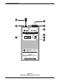
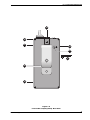
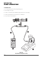
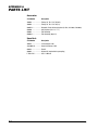
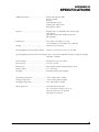
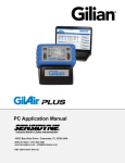
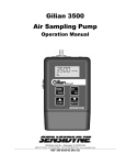
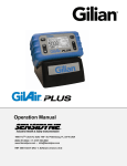
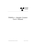
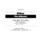
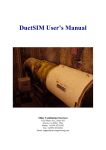
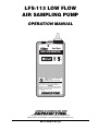
LFS-113 LOW FLOW
AIR SAMPLING PUMP
OPERATION MANUAL
Made in USA
FLOW ADJ
Patent Pending
Dual Mode
LOW FLOW SAMPLER
Model LFS-113DC
B
ON
F
OFF
TIME (MIN)
Personal Air Sampler
®
LISTED 17G9
MODEL LFS-113D / LFS-113DC
Intrinsically Safe Portable Air Sampling Pump for use in
hazardous locations: Class I Groups A,B,C,D; Class II
Groups E,F,G; Class III. Temperature Code T3C.
WARNING
Substitution of components may impair Intrinsic
Safety. Use only with UL Listed Portable Air
Sampling Pump Battery Pack.
Made by
1000 112th Circle N, Suite 100 • St. Petersburg, Florida 33716 USA
(800) 451-9444 • (727) 530-3602 • (727) 539-0550 [FAX] • www.sensidyne.com
REF F-PRO-1725 (F)
LFS-113 LOW FLOW
AIR SAMPLING PUMP
OPERATION MANUAL
Made in USA
FLOW ADJ
Patent Pending
Dual Mode
LOW FLOW SAMPLER
Model LFS-113DC
B
ON
F
OFF
TIME (MIN)
Personal Air Sampler
®
LISTED 17G9
MODEL LFS-113D / LFS-113DC
Intrinsically Safe Portable Air Sampling Pump for use in
hazardous locations: Class I Groups A,B,C,D; Class II
Groups E,F,G; Class III. Temperature Code T3C.
WARNING
Substitution of components may impair Intrinsic
Safety. Use only with UL Listed Portable Air
Sampling Pump Battery Pack.
Made by
LFS-113 LOW FLOW AIR SAMPLING PUMP
PROPRIETARY NOTICE
This manual was prepared exclusively for the owner of the Sensidyne LFS-113 Low Flow Air Sampling Pump. The material within this manual is proprietary information and is to be used only to understand, operate, and service the instrument.
By receiving this document, the recipient agrees that neither this document nor the information disclosed within nor any
part thereof shall be reproduced or transferred, physically, electronically or in any other form, or used or disclosed to others for manufacturing or for any other purpose except as specifically authorized in writing by Sensidyne, LP.
COPYRIGHT NOTICE
© 2003, © 2008 Sensidyne, LP All Rights Reserved. No part of this document may be reproduced, transmitted, transcribed,
stored in a retrieval system, or translated into any language in any form by any means without the prior written permission of
Sensidyne, LP.
TRADEMARK NOTICE
Sensidyne, the Sensidyne logo, Gilian, and the Gilian logo are registered trademarks. These trademarks are protected through
use and registration in the United States. The trademarks and servicemarks used in this document are the property of their
respective companies and are used only for informational and explanatory purposes.
DISCLAIMER
THE SELLER ASSUMES NO RESPONSIBILITY WHATSOEVER, TO ANY PARTY WHOSOEVER, FOR ANY
PROPERTY DAMAGE, PERSONAL INJURY, OR DEATH RECEIVED BY OR RESULTING FROM, IN
WHOLE, OR IN PART, THE IMPROPER USE, INSTALLATION, OR STORAGE OF THIS PRODUCT BY THE
USER, PERSON, FIRM, ENTITY, CORPORATION OR PARTY NOT ADHERING TO THE INSTRUCTIONS
AND WARNINGS IN THIS MANUAL, OR OTHERWISE PROVIDED BY THE SELLER OR FROM NOT ADHERING TO ALL FEDERAL, STATE, AND LOCAL ENVIRONMENTAL AND OCCUPATIONAL HEALTH AND
SAFETY LAWS AND REGULATIONS.
THE SELLER SHALL NOT BE LIABLE FOR DIRECT, INDIRECT, CONSEQUENTIAL, INCIDENTAL OR
OTHER DAMAGES RESULTING FROM THE SALE AND USE OF ANY GOODS AND SELLERS’ LIABILITY
HEREUNDER SHALL BE LIMITED TO REPAIR OR REPLACEMENT OF ANY GOODS FOUND DEFECTIVE.
THIS WARRANTY IS IN LIEU OF ALL OTHER WARRANTIES, EXPRESSED OR IMPLIED, INCLUDING BUT
NOT LIMITED TO THE IMPLIED WARRANTIES OF MERCHANTABILITY AND FITNESS FOR USE OR FOR
A PARTICULAR PURPOSE WHICH ARE EXPRESSLY DISCLAIMED.
4
REF F-PRO-1725 (F)
TABLE OF
CONTENTS
• PREFACE
• Notices ................................................................................................................................... 4
• WARNINGS ............................................................................................................................ 6
SECTION ONE: INTRODUCTION
• Components .......................................................................................................................... 7
SECTION TWO: PUMP OPERATION
2.1
Equipment Set-Up ........................................................................................................... 10
2.2
Field Calibration/Flow Verification ................................................................................ 11
2.3
Taking A Sample .............................................................................................................14
SECTION THREE: MAINTENANCE
3.1
Battery Maintenance ....................................................................................................... 15
3.2
Filter Maintenance ..........................................................................................................15
SECTION FOUR: APPENDICES
• Appendix A: Parts List ........................................................................................................ 16
• Appendix B: Specifications .................................................................................................17
• Appendix C: Service ........................................................................................................... 18
LIST OF FIGURES
1.1
1.2
LFS-113 Air Sampling Pump: Front View ................................................................8
LFS-113 Air Sampling Pump: Rear View .................................................................9
2.1
2.2
2.3
2.4
Field Calibration Equipment Set-Up ....................................................................... 10
Field Calibration: Constant Flow ........................................................................... 12
Field Calibration: Multi-Flow .................................................................................. 13
Sampling .................................................................................................................14
REF F-PRO-1725 (F)
5
WARNINGS
READ AND UNDERSTAND ALL WARNINGS AND INSTRUCTIONS BEFORE USE
Failure to read, understand, and comply with ALL accompanying literature, product labels, and warnings could result in property
damage, severe personal injury, or death.
Read and understand ALL applicable environmental health and safety laws and regulations. Ensure complete compliance with ALL applicable
laws and regulations before and during use of this product.
DO NOT remove, cover, or alter any label or tag on this product, its accessories, or related products.
UNDER NO CIRCUMSTANCES should this product be used except by qualified, trained, technically competent personnel.
DO NOT operate this product should it malfunction, require repair, or have a cracked or broken case. DO NOT repair or modify, except
as specified in Operation Manual. No user servicable parts located within case. Service to be performed by Sensidyne Authorized Service
Departments only.
Use ONLY specified Sensidyne parts when performing maintenance procedures described in this manual. Intrinsic safety certifications
become void by substitution of components, unauthorized repair or alteration.
This product is intended for both indoor and outdoor use when protected from splashed or wind blown liquids. The unit is not
waterproof so NEVER submerge the unit in water. Pump failure or faulting may result.
Possible static hazard. Do not rub with dry cloth.
DO NOT charge battery in an explosive atmosphere.
This product uses rechargeable Nickel-Cadmium batteries. ALWAYS fully charge before use. Use only battery pack and chargers
specified in Operation Manual. DO NOT insert any foreign objects into contact slot. Shorting contacts will blow protective fuse.
If the equipment is likely to come into contact with aggressive substances, then it is the responsibility of the user to take suitable
precautions that prevent it from being adversely affected, thus ensuring that the type of protection is not compromised. Examples of
aggressive substances are acidic liquids or gases that may attack metals, or solvents that may affect polymeric materials. Examples
of suitable precautions are regular checks as part of routine inspections or establishing from material data sheets that it is resistant to
specific chemicals.
DO NOT operate with a dirty or blocked inlet filter or kinked tubing. Pump failure or faulting may result.
Caution: Both charger and battery become warm during charging.
If further translation is required, please contact Schauenburg Electronic Technologies GmbH, the Sensidyne EU Authorized Representative.
6
REF F-PRO-1725 (F)
SECTION ONE
INTRODUCTION
• COMPONENTS
• See Figures 1.1 and 1.2
(1) Inlet Boss
The Inlet Boss is located on the filter housing and
provides a built-in means of attaching tubing for
suction sampling.
(9) Discharge (Bag Sampling) Boss
This is an accessory which, when installed into
the Outlet Port, provides a means for filling air
sampling bags.
(2) Air Inlet Pump Filter
A 10 Micron Nylon Air Inlet Pump Filter protects
the pump assembly from dirt.
(11)Charging Jack
The Charging Jack receptacle is used to connect
a charger for recharging the internal battery
pack.
(3) Flow Adjustment (requires slotted screwdrivwer).
(12)Belt Clip
(4) Battery Check
This green LED (B) indicates that sufficient battery
power is available to run the pump for an 8 hour
period under normal load conditions.
(5) On/Off Switch
(6) Fault Indicator
This red LED (F) indicates a flow fault due to excessive pressure or insufficient battery voltage to
maintain flow.
(7) Clock Display (DC Model only)
The Clock Display shows the continuous run-time
(in minutes, to two decimal places), and will lockin the sample time upon fault indication. The time
will reset to zero when the power switch is turned
OFF and then back ON again.
(13)Rechargeable Battery Pack
(14)Tube Breaker Assembly.
(15)Mode Indicator
The Mode Indicator visually confirms the sampling mode selected (via a Black/White indicator)
(16)Mode Selector
The Mode Selector is used to change the sampling mode. The selector is used for unlocking,
indexing, and re-locking the mode selector
valve while changing from Constant Flow Mode
to Constant Pressure (Multi-Flow) Mode.
(17)Hex Key
(8) Outlet Port
The Outlet Port provides a receptacle for the discharge (bag sampling) boss accessory. The cap
screw prevents dirt from entering the Outlet Port
when not in use.
REF F-PRO-1725 (F)
7
LFS-113 LOW FLOW AIR SAMPLING PUMP
9
1
2
8
Made in USA
FLOW ADJ
Patent Pending
3
Dual Mode
LOW FLOW SAMPLER
Model LFS-113DC
7
4
B
ON
F
OFF
5
TIME (MIN)
6
Personal Air Sampler
®
LISTED 17G9
MODEL LFS-113D / LFS-113DC
Intrinsically Safe Portable Air Sampling Pump for use in
hazardous locations: Class I Groups A,B,C,D; Class II
Groups E,F,G; Class III. Temperature Code T3C.
WARNING
Substitution of components may impair Intrinsic
Safety. Use only with UL Listed Portable Air
Sampling Pump Battery Pack.
Made by
Figure 1.1
LFS-113 Air Sampling Pump: Front View
8
REF F-PRO-1725 (F)
LFS-113 LOW FLOW AIR SAMPLING PUMP
14
10
11
15
16
17
12
13
Figure 1.2
LFS-113 Air Sampling Pump: Rear View
REF F-PRO-1725 (F)
9
SECTION TWO
PUMP OPERATION
2.1 Equipment Set-Up
1) Use an LFS-113 pump with a fully charged battery pack.
2) Attach tubing to the pump.
3) Connect a constant flow [3A] or Multi-Flow [3B] collection device to the tubing.
4) Connect the tubing from the collection device to a Gilibrator 2.
5) Set up and turn on the Gilibrator 2.
UNIVERSAL TUBE
HOLDER SYSTEM
(THH-L-240)
Patent Pending
Made in USA
UNIVERSAL TUBE
HOLDER SYSTEM
(THH-L-240)
Patent Pending
Made in USA
3B
3A
UNIVERSAL TUBE
HOLDER SYSTEM
(THH-L-240)
Patent Pending
Made in USA
4
2
Made in USA
FLOW ADJ
Patent Pending
Dual Mode
LOW FLOW SAMPLER
Model LFS-113DC
B
ON
F
OFF
TIME (MIN)
Personal Air Sampler
®
LISTED 17G9
MODEL LFS-113D / LFS-113DC
Intrinsically Safe Portable Air Sampling Pump for use in
hazardous locations: Class I Groups A,B,C,D; Class II
Groups E,F,G; Class III. Temperature Code T3C.
WARNING
Substitution of components may impair Intrinsic
Safety. Use only with UL Listed Portable Air
Sampling Pump Battery Pack.
Made by
1
5
Figure 2.1
Field Calibration Equipment Set-Up
10
REF F-PRO-1725 (F)
LFS-113 LOW FLOW AIR SAMPLING PUMP
2.2 Field Calibration/Flow Verification
Field calibration (flow rate verification) must be performed before sampling and when setting the flow
rate.
5) Turn on the pump using a pointed instrument
such as ball point pen [5].
• See Figure 2.2 for Constant Flow
6) Make sure the Gilibrator 2 is on and working.
• See Figure 2.3 for Multi-Flow
7) Set the pump flow rate as follows:
1) Insert the hex key [1] into the hex head screw on
the pump.
2) Turn the key counterclockwise [2] to change the
mode.
3) Continue turn the key until the mode indicator
shows black for constant flow [Fig. 2.2, #3] or
white for multi-flow [Fig. 2.3, #3].
4) Turn the key clockwise [4] to lock your selection
into place.
REF F-PRO-1725 (F)
Constant Flow: Use a slotted screwdriver to
make flow adjustments on the pump itself
[Fig. 2.2, #6].
Multi-Flow: Use a slotted screwdriver to make individual flow adjustments on the sampling device
[Fig. 2.3, #6].
8) When desired flow rate has been reached, turn off
pump and Gilibrator 2. The pump is now ready
for sampling.
11
LFS-113 LOW FLOW AIR SAMPLING PUMP
UNIVERSAL TUBE
HOLDER SYSTEM
(THH-L-240)
Patent Pending
Made in USA
6
Made in USA
FLOW ADJ
Patent Pending
Dual Mode
LOW FLOW SAMPLER
Model LFS-113DC
B
ON
F
OFF
TIME (MIN)
5
Personal Air Sampler
LISTED 17G9
MODEL LFS-113D / LFS-113DC
®
Intrinsically Safe Portable Air Sampling Pump for use in
hazardous locations: Class I Groups A,B,C,D; Class II
Groups E,F,G; Class III. Temperature Code T3C.
WARNING
Substitution of components may impair Intrinsic
Safety. Use only with UL Listed Portable Air
Sampling Pump Battery Pack.
Made by
3
2
4
1
Figure 2.2
Field Calibration: Constant Flow
12
REF F-PRO-1725 (F)
LFS-113 LOW FLOW AIR SAMPLING PUMP
6
UNIVERSAL TUBE
HOLDER SYSTEM
(THH-L-240)
Patent Pending
Made in USA
UNIVERSAL TUBE
HOLDER SYSTEM
(THH-L-240)
Patent Pending
Made in USA
Made in USA
FLOW ADJ
Patent Pending
Dual Mode
LOW FLOW SAMPLER
Model LFS-113DC
B
ON
F
OFF
5
TIME (MIN)
Personal Air Sampler
®
LISTED 17G9
MODEL LFS-113D / LFS-113DC
Intrinsically Safe Portable Air Sampling Pump for use in
hazardous locations: Class I Groups A,B,C,D; Class II
Groups E,F,G; Class III. Temperature Code T3C.
WARNING
Substitution of components may impair Intrinsic
Safety. Use only with UL Listed Portable Air
Sampling Pump Battery Pack.
Made by
3
2
4
1
Figure 2.3
Field Calibration: Multi-Flow
REF F-PRO-1725 (F)
13
LFS-113 LOW FLOW AIR SAMPLING PUMP
2.3 Taking A Sample
1) Use a pointed instrument such as a ball point pen to turn on the pump.
2) Place the pump, tubing and sampling device on the worker as shown in Figure 2.4.
3) When sampling is completed use a pointed instrument such as a ball point pen to turn off the pump.
Record the sample data.
Note for Clock Models
When the pump is shut off after a sample run, the accumulated run time minutes (to the nearest 0.01
minute) are displayed. To calculate totaled air volume sampled, use the following formula:
Total Air Volume (Liters) = Air Flow Rate (cc/min) x Sample Time (minutes) ÷ 1000 cc/Liter
Paten
Madet Pendin
in USAg
FLOW ADJ
Patent Pending
UNI
HOLVER
DERSAL
TUB
(THH SYS
E
-L-24 TEM
0)
Made in USA
1
Made in USA
FLOW ADJ
Patent Pending
Dual Mode
Dual Mode
LOW FLOW SAMPLER
LOW FLOW SAMPLER
Model LFS-113DC
Model LFS-113DC
B
ON
F
OFF
TIME (MIN)
ON
F
OFF
TIME (MIN)
Personal Air Sampler
®
B
3
Personal Air Sampler
LISTED 17G9
MODEL LFS-113D / LFS-113DC
®
Intrinsically Safe Portable Air Sampling Pump for use in
hazardous locations: Class I Groups A,B,C,D; Class II
Groups E,F,G; Class III. Temperature Code T3C.
WARNING
Substitution of components may impair Intrinsic
Safety. Use only with UL Listed Portable Air
Sampling Pump Battery Pack.
LISTED 17G9
MODEL LFS-113D / LFS-113DC
Intrinsically Safe Portable Air Sampling Pump for use in
hazardous locations: Class I Groups A,B,C,D; Class II
Groups E,F,G; Class III. Temperature Code T3C.
WARNING
Substitution of components may impair Intrinsic
Safety. Use only with UL Listed Portable Air
Sampling Pump Battery Pack.
Made by
Made in USA
FLOW ADJ
Patent Pending
Made by
Dual Mode
LOW FLOW SAMPLER
Model LFS-113DC
B
ON
F
OFF
TIME (MIN)
Personal Air Sampler
®
LISTED 17G9
MODEL LFS-113D / LFS-113DC
Intrinsically Safe Portable Air Sampling Pump for use in
hazardous locations: Class I Groups A,B,C,D; Class II
Groups E,F,G; Class III. Temperature Code T3C.
WARNING
Substitution of components may impair Intrinsic
Safety. Use only with UL Listed Portable Air
Sampling Pump Battery Pack.
Made by
2
Figure 2.4
Sampling
14
REF F-PRO-1725 (F)
SECTION THREE
MAINTENANCE
3.1 Battery Maintenance
• Chargers
NOTE
Do not charge battery pack while
in an explosive atmosphere.
The LFS-113 pump uses rechargeable Nickel-Cadmium
batteries that must be fully charged and properly
maintained for maximum run time. The battery pack is
rated at 4.8 Volts (720 mAh).
Make certain charger plug is fully inserted into jack on
battery pack (see Figure 1.2, #11 for charger jack
location).
CAUTIONS & NOTES
Both charger and battery pack become warm during
charging.
Do not short battery terminals. Shorting will blow internal fuse.
• Memory Effect
Nickel-Cadmium batteries will develop reduced capacity when they are not fully discharged and then fully
recharged after sampling. Memory effect takes time to
develop and can usually be eliminated by performing
two complete discharge/recharge cycles on the pump.
• Leakage Current
Nickel-Cadmium batteries always have a small internal
leakage current. If the battery pack has been removed
from the charger for more than two days without use,
it will require additional charging to restore it to full
capacity. This process can be repeated two or three
times without causing signs of memory effect.
Single Station Charger
A constant-rate single-station charger that is suitable
for both overnight charging and weekend charging.
LFATR Multi-Station Charger
A dual rate charger offering five-station timed
constant-rate charging that automatically defaults to
trickle charge.
NOTE
Both chargers can be damaged by line transients and
overvoltage. While not a common problem, long term
reliability can be improved by use of a
surge/overvoltage protector.
3.2 Filter Maintenance
Under normal operating conditions, the pump filter
should be changed after approximately six months or
250 hours of operation, or when needed.␣ Failure to
change the filter as it becomes dirty will decrease the
pump’s back pressure capability and performance envelope.
• See Figure 1.1, #1
Blow all dust and debris from around the Filter
Housing.␣ Grasp the knurled edge of the filter housing
assembly and rotate counterclockwise.␣ Check the new
filter housing assembly to make sure that the sealing
O-ring is present on the internal boss.␣ Install the new
Filter Housing Assembly onto the pump rotating the
knurled edge clockwise.␣ Do Not Overtighten!
Battery pack has an estimated life of 300–500 charge/
discharge cycles, depending on use. Table below shows
estimated battery life based on usage level.
Pump Usage
Weekly Use
Est. Battery Life
High ......................... 40-60 hrs ................. 1.0-1.5 yrs
Medium .................... 20-39 hrs ................. 1.5-2.5 yrs
Low .......................... < 20 hrs ................... 2.5 yrs
REF F-PRO-1725 (F)
15
APPENDIX A
PARTS LIST
Accessories
Part Number
Description
200504 ........................ Tubing, 1/8” ID x 1/16” W (10 ft)
200505 ........................ Tubing, 1/8” ID x 1/16” W (3 ft)
800565-4 ..................... Diagnostic Panel with Carrying Case (2–50cc, 20–200cc, 50–800cc)
800400 ........................ Carrying Case (18” x 13” x 7”)
800093 ........................ Filter Assembly
800093-3 ..................... Filter Assembly (pkg of 3)
Spare Parts
Part Number
Description
400324 ........................ 5-Unit Charger, 120V
298-0005-01 ............... Single Unit Charger, 120V
800222 ........................ Tool Kit
800685 ........................ Air Boss Kit (required for bag sampling)
F-PRO-1725 ................. LFS-113 Manual
16
REF F-PRO-1725 (F)
APPENDIX B
SPECIFICATIONS
Additional Features ....................................... Flow Fault indication LED
Batt check LED
Belt clip
Dual filtration system
Sorbent tube end breaker
External flow adjust
Options .......................................................... Elapsed timer clock module (DC models only):
LCD display
automatic instant-fault shutdown function
RFI shielding
Dimensions ................................................... 2.50” (W) x 1.38” (H) x 4.63” (L)
63.5 mm (W) x 34.9 mm (H) x 117.5 mm (L)
Weight ........................................................... Main Unit: 12 oz (340 g)
Operating Range (Constant Flow Mode) .... 20–200 cc/min, back pressures to 25” H2O
Operating Range (Constant Pressure Mode) 1–350 cc/min, flows adjustable through a single or multiple
tube flow controller.
Pressure Range ............................................. Backpressure up to 25” H2O.
Flow Control ................................................. ± 5% of set point
Battery Type .................................................. Rechargeable Nickel-Cadmium battery pack
Battery Output .............................................. 4.8 v, 500 mAh
Charging ........................................................ Internal (external with adapter).
Operating Temperature ................................ -20° to 45°C (-4°F to 113°F)
Storage Temperature .................................... -40° to 45°C (-40°F to 113°F)
Charging Temperature .................................. 0° to 45°C (32°F to 113°F)
Safety Approvals: .......................................... UL Listed Intrinsically Safe
for use in Class I Groups A, B, C, D,
Class II Groups E, F, G; Class III
Temperature Code T3C
REF F-PRO-1725 (F)
17
APPENDIX C
SERVICE
Domestic Service
Sensidyne, LP
1000 112th Circle N, Suite 100
St. Petersburg, Florida 33716 USA
800-451-9444
727-530-3602
727-539-0550 [Main fax]
727-538-0671 [Service fax]
e-mail: [email protected]
web: www.sensidyne.com
18
REF F-PRO-1725 (F)
Manufactured by:
Sensidyne, LP
1000 112th Circle N, Suite 100
St. Petersburg, Florida 33716
USA
800-451-9444 • 727-530-3602 • 727-539-0550 [fax]
www.sensidyne.com • [email protected]