1
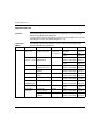
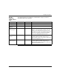
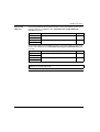
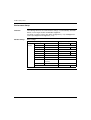
Magelis XBT G & XBT GT
Modbus (RTU) driver
35007086 03
eng
2
Table of Contents
Safety Information . . . . . . . . . . . . . . . . . . . . . . . . . . . . . . . . . . . . 5
About the Book . . . . . . . . . . . . . . . . . . . . . . . . . . . . . . . . . . . . . . . 7
Chapter 1
Modbus (RTU) Driver . . . . . . . . . . . . . . . . . . . . . . . . . . . . . . . . . . 9
At a Glance . . . . . . . . . . . . . . . . . . . . . . . . . . . . . . . . . . . . . . . . . . . . . . . . . . . . . . 9
System Structure. . . . . . . . . . . . . . . . . . . . . . . . . . . . . . . . . . . . . . . . . . . . . . . . . 10
Cable Diagrams. . . . . . . . . . . . . . . . . . . . . . . . . . . . . . . . . . . . . . . . . . . . . . . . . . 14
Supported Equipment Variable Addresses . . . . . . . . . . . . . . . . . . . . . . . . . . . . . 21
Consecutive Equipment Addresses . . . . . . . . . . . . . . . . . . . . . . . . . . . . . . . . . . 26
Environment Setup . . . . . . . . . . . . . . . . . . . . . . . . . . . . . . . . . . . . . . . . . . . . . . . 28
I/O Manager Configuration . . . . . . . . . . . . . . . . . . . . . . . . . . . . . . . . . . . . . . . . . 30
Driver Configuration . . . . . . . . . . . . . . . . . . . . . . . . . . . . . . . . . . . . . . . . . . . . . . 31
Equipment Configuration. . . . . . . . . . . . . . . . . . . . . . . . . . . . . . . . . . . . . . . . . . . 33
Equipment Variable Address Configuration . . . . . . . . . . . . . . . . . . . . . . . . . . . . 36
Chapter 2
Modbus RTU Communication: General Principles . . . . . . . . . 41
At a Glance . . . . . . . . . . . . . . . . . . . . . . . . . . . . . . . . . . . . . . . . . . . . . . . . . . . . .
General . . . . . . . . . . . . . . . . . . . . . . . . . . . . . . . . . . . . . . . . . . . . . . . . . . . . . . . .
Operating Principle . . . . . . . . . . . . . . . . . . . . . . . . . . . . . . . . . . . . . . . . . . . . . . .
Example of a Serial Modbus RTU Communication Bus . . . . . . . . . . . . . . . . . . .
Chapter 3
41
42
44
46
Appendix . . . . . . . . . . . . . . . . . . . . . . . . . . . . . . . . . . . . . . . . . . . 47
Modbus function codes and exception error codes. . . . . . . . . . . . . . . . . . . . . . . 47
Index
. . . . . . . . . . . . . . . . . . . . . . . . . . . . . . . . . . . . . . . . . . . . . . 51
3
4
Safety Information
§
Important Information
NOTICE
Read these instructions carefully, and look at the equipment to become familiar with the
device before trying to install, operate, or maintain it. The following special messages
may appear throughout this documentation or on the equipment to warn of potential
hazards or to call attention to information that clarifies or simplifies a procedure.
The addition of this symbol to a Danger or Warning safety label indicates
that an electrical hazard exists, which will result in personal injury if the
instructions are not followed.
This is the safety alert symbol. It is used to alert you to potential personal
injury hazards. Obey all safety messages that follow this symbol to avoid
possible injury or death.
DANGER
DANGER indicates an imminently hazardous situation, which, if not avoided, will
result in death, serious injury, or equipment damage.
WARNING
WARNING indicates a potentially hazardous situation, which, if not avoided, can result
in death, serious injury, or equipment damage.
CAUTION
CAUTION indicates a potentially hazardous situation, which, if not avoided, can result
in injury or equipment damage.
35007086 03 03/2006
5
Safety Information
PLEASE NOTE
Electrical equipment should be serviced only by qualified personnel. No responsibility is
assumed by Schneider Electric for any consequences arising out of the use of this
material. This document is not intended as an instruction manual for untrained persons.
© 2005 Schneider Electric. All Rights Reserved.
6
35007086 03 03/2006
About the Book
At a Glance
Document Scope
Related
Documents
35007086 03 03/2006
This documentation presents Modbus (RTU) driver for Magelis XBT G & XBT GT.
Title of Documentation
Reference Number
Vijeo Designer User manual
Included in the Vijeo Designer CDROM
Vijeo Designer Tutorial
Included in the Vijeo Designer CDROM
Magelis XBT G Modbus TCP/IP driver
Included in the Vijeo Designer CDROM
Magelis XBT G Modbus Plus driver
Included in the Vijeo Designer CDROM
7
About the Book
Product Related
Warnings
WARNING
LOSS OF CONTROL
z
z
z
z
The designer of any control scheme must consider the potential failure modes
of control paths and, for certain critical control functions, provide a means to
achieve a safe state during and after a path failure. Examples of critical control
functions are emergency stop and overtravel stop.
Separate or redundant control paths must be provided for critical control functions.
System control paths may include communication links. Consideration must be
given to the implications of unanticipated transmission delays or failures of the link. *
Each implementation of Magelis XBT G and XBT GT must be individually and
thoroughly tested for proper operation before being placed into service.
Failure to follow this instruction can result in death, serious injury, or
equipment damage.
* For additional information, refer to NEMA ICS 1.1 (latest edition), "Safety
Guidelines for the Application, Installation, and Maintenance of Solid State Control"
and to NEMA ICS 7.1 (latest edition), "Safety Standards for Construction and Guide
for Selection, Installation and Operation of Adjustable-Speed Drive Systems".
User Comments
8
We welcome your comments about this document. You can reach us by e-mail at
[email protected]
35007086 03 03/2006
Modbus (RTU) Driver
1
At a Glance
Subject of this
chapter
This chapter explains how to connect the target machine with Modbus RTU
equipment. For information about how to use the Vijeo-Designer software, please
refer to the Vijeo-Designer Online Help.
The types of target machines that are compatible with Vijeo-Designer depends on
the version of Vijeo-Designer. For information about the compatibility of target
machines, please refer to the Vijeo-Designer Online or User Manual help.
Note: target machines mean Magelis XBT G/XBT GT products.
What's in this
Chapter?
35007086 03 03/2006
This chapter contains the following topics:
Topic
Page
System Structure
10
Cable Diagrams
14
Supported Equipment Variable Addresses
21
Consecutive Equipment Addresses
26
Environment Setup
28
I/O Manager Configuration
30
Driver Configuration
31
Equipment Configuration
33
Equipment Variable Address Configuration
36
9
Modbus (RTU) Driver
System Structure
Overview
The following table describes tested system configurations for connecting target
machines with Modbus RTU equipment.
To view a cable connection diagram for a particular communication format, see the
Cable diagrams section (See Cable Diagrams, p. 14).
Connection
XBT G
Protocol
The following table describes the basic system setup for connecting the target
machine to Modbus RTU equipment.
CPU
Modbus RTU Twido (Slave
address =1)
Link I/F
Comm.Format
Modbus Slave
auxiliary terminal port
RS-485, 19200, Com1 D-Sub25 +
Data 8, parity
XBT ZG999
none, Stop bit 1, Com2
D-Sub 9
Cable
Diagram 1
RS-485
Com1
SUb-D25 + XBT ZG999
Cable
diagram 1
Com2
D-Sub 9
Cable
diagram 3
Twido (Slave
TWDNOZ485D
address =1 to 247) TWDNAC485D
10
XBT G Connector
Diagram
Cable
diagram 3
TSX37 Micro
Modbus Slave
auxiliary terminal port
RS-485
Com1
SUb-D25 + XBT ZG999
Cable
Diagram 5
Quantum
CPU’S Modbus port
Sub-D9
RS-232C
Com1
SUb-D25 + XBT ZG999
Cable
Diagram 2
Momentum
CPU’s Modbus port
RJ45
RS-232C
Com1
SUb-D25 + XBT ZG999
Cable
Diagram 2
TSX57 Premium
SCY2160
RS-485
Com1
SUb-D25 + XBT ZG999
Cable
Diagram 6
TESys Zelio
(SR3MBU01BD)
RJ45
RS-485
Com1
SUb-D25 + XBT ZG999
Cable
Diagram 8
Advantys STB
HE connector on NIM
RS-232C
Com2
Sub-D9
Cable
Diagram 7
Any Modbus
Equipment
TSX SCA 62
Socket subscriber
RS-485
Com1
SUb-D25 + XBT ZG999
Cable
Diagram 4
Modelbus Hub
LU9GC3
RS-485
Com1
SUb-D25 + XBT ZG999
Cable
Diagram 8
35007086 03 03/2006
Modbus (RTU) Driver
Note:
z To connect XBT G/XBT GT to TSX-SCG116, use XBT ZG999 + XBT Z928
z To connect XBT G/XBT GT to TSX17, use XBT ZG999 + XBT Z917
z To connect XBT G/XBT GT to V4 CPU through TSXLES64/74, use XBT ZG999
+ XBT Z948 on HE13/14
35007086 03 03/2006
11
Modbus (RTU) Driver
Connection
XBT GT1000
series
Protocol
The following table describes the basic system setup for connecting the target
machine to Modbus RTU equipment.
Link I/F
Comm.Format XBT GT
Connector
Diagram
Modbus RTU Twido
Modbus Slave auxiliary
terminal port
TWDNOZ485D
TWDNAC485D
RS-485
Com1 RJ45
Cable Diagram 10
Micro
Modbus Slave auxiliary
terminal port
RS-485
Com1 RJ45
Cable Diagram 10
Momentum
CPU’s
Modbus port
RS-232C
Com1 RJ45 + Cable diagram 16
XBT ZG939
TSX57
PremiumTSX57
Premium UNITY
SCY2160
D-Sub25
RS-485
Com1 RJ45 +
XBT ZG939
Cable diagram 14
SCY2160
SCP114
RS-485
Com1 RJ45
Cable Diagram 15
TESys Zelio (SR3 RJ45
MBU01BD)ATV
RS-485
Com1 RJ45
Cable Diagram 12
Advantys
HE13
RS-232C
Com1 RJ45
Cable Diagram 17
Any Modbus
Equipment
Modbus HUB
Modbus-T
SCA62 Socket
Subscriber
RS-485
Com1 RJ45
Cable Diagram 11
Cable Diagram 15
Cable Diagram 13
12
CPU
35007086 03 03/2006
Modbus (RTU) Driver
Connection
XBT GT2000
series
Protocol
The following table describes the basic system setup for connecting the target
machine to Modbus RTU equipment.
CPU
Link I/F
Comm.
Format
XBT GT Connector Diagram
Modbus Slave auxiliary
terminal port
TWDNOZ485D
TWDNAC485D
RS-485
Com2 RJ45
Cable Diagram 10
Com1 D-Sub-D9 +
XBT ZG909
Cable diagram 18
Modbus Slave auxiliary
terminal port
RS-485
Com2 RJ45
Cable diagram 25
Com1 D-Sub-D9 +
XBT ZG909
Cable diagram 26
Quantum
CPU’S Modbus port Sub-D9 RS-232C Com1 D-Sub-D9 +
XBT ZG919
Cable Diagram 19
Momentum
CPU’s Modbus port
RS-232C Com1 D-Sub-D9 +
XBT ZG999
Cable Diagram 21
Premium
SCY2160
RS-485
Com2 RJ45 +
XBT ZG939
Cable Diagram 14
Com1 D-Sub-D9
+XBT ZG909
Cable Diagram 22
Modbus RTU Twido
Micro
TESys Zelio
RJ45
(SR3MBU01BD)
RS-485
Com2 RJ45
Cable Diagram 12
Com1 D-Sub9 +
XBT ZG909
Cable Diagram 20
Advantys
HE13
RS-232C Com1 D-Sub-D9
Cable Diagram 24
Any Modbus
Equipment
Modbus HUB
TSXPACC01 Socket
subscriber
Modbus-T
RS-485
COM2 RJ45
Cable Diagram 11
Cable diagram 15
Cable diagram 13
TSXSCA62 Socket
subscriber
RS-485
Com1 D-Sub-D9 +
XBT ZG909
Cable Diagram 23
35007086 03 03/2006
13
Modbus (RTU) Driver
Cable Diagrams
Overview
Schneider Electric recommends using the connection schemes in the following
diagrams, as specified in the preceding connection tables.
z
Diagram 1 XBT G
series
Ground the equipment and the terminal according to your country’s applicable
standard. For details, refer to the equipment manual.
RS 485
Target Machine
XBT Z968 (2.5m [8.20ft])
XBT Z9681 (5m [16.25ft)
Equipment
Cable
XBT ZG999 Adapter
(connects to COM1)
Diagram 2 XBT G
series
RS 232C
Target Machine
XBT Z9710 (2.5m [8.20ft])
for Quantum
XBT Z9711 (3m [9.84ft])]
for Momentum
Equipment
Cable
XBT ZG999 Adapter
(connects to COM1)
Diagram 3 XBT G
series
RS 485
Target Machine
Equipment
TSXPCX1031 (2.5m [8.20ft])
Cable
Twido:TER Direct Mode
Micro: Other Direct Mode
(connects to COM2)
14
35007086 03 03/2006
Modbus (RTU) Driver
Diagram 4 XBT G
series
RS 485
Equipment
Target Machine
XBT Z908 (2.5m [8.20ft])
Modbus RS-485 Bus
Cable
TSX SCA 62
Subscriber Socket
(0 to 2 [15-pin] connections)
XBT ZG999 Adapter
(connects to COM1)
Diagram 5 XBT G
series
RS 485
Equipment
Target Machine
XBT Z968 (2.5m [8.20ft])
Cable
XBT ZG999 Adapter
(connects to COM1)
Diagram 6 XBT G
series
TSX P ACC 01
Subscriber Socket
(1 to 3 [mini-din] connections)
RS 485
Target Machine
Equipment
XBT Z918 (2.5m [8.20ft])
Cable
SCY2160
SCY2160
XBT ZG999 Adapter
(connects to COM1)
Diagram 7 XBT G
series
RS 232C
Target Machine
Equipment
XBT XCA4002 (2m [6.56ft])
Cable
(connects to COM2)
35007086 03 03/2006
15
Modbus (RTU) Driver
Diagram 8 XBT G
series
Equipment
Target Machine
XBT Z938-V2 (2.5m
[8.20ft])
Equipment
Cable
LU9GC3
Note: For point to point connection, connect the XBT Z to the RJ45 equipment’s
connector. Diagram 8 is using RS485 2 Wires bus. For the XBT Z938-V2, make
sure that this exact reference is written on the cable.
Diagram 10
XBT GT series
RS 485
Target Machine
Equipment
XBT Z9780 (2.5m [8.20ft])
Cable
(Connect to RJ45)
Diagram 11
XBT GT series
RS 485
Equipment
Target Machine
VW3A8306R10 (1m
[3.28ft])
Equipment
Cable
(Connect to Com 1 RJ45)
Diagram 12
XBT GT series
LU9GC3
RS 485
Target Machine
Equipment
VW3A8306R10 (1m [3.28ft])
Cable
16
35007086 03 03/2006
Modbus (RTU) Driver
Diagram 13
XBT GT series
RS 485
Target Machine
2 Wires Modbus Network
VW3A8306TF10 (1m [3.28ft])
Modbus-T
Diagram 14
XBT GT series
RS 485
Target Machine
Equipment
XBT Z918 (2.5m [8.20ft])
Cable
XBT ZG939
Diagram 15
XBT GT series
RS 485
Equipment
Target Machine
Modbus RS-485 Bus
VW3A8306 (3m [9.84ft])
Cable
RJ45
Diagram 16
XBT GT series
TSX SCA 62
Subscriber Socket
(0 to 2 [15-pin] connections)
RS 485
Target Machine
Equipment
XBT Z9711 (3m [9.84ft])
Cable
XBT ZG939
35007086 03 03/2006
17
Modbus (RTU) Driver
Diagram 17
XBT GT series
RS 485
Target Machine
Equipment
XBT Z988 (2.5m [8.20ft])
Cable
XBT ZG939
Diagram 18
XBT GT series
RS 485
Target Machine
Equipment
XBT Z968 (2.5m [8.20ft])
Cable
XBT ZG909
Diagram 19
XBT GT series
RS 485
Target Machine
Equipment
XBT Z9710 (2,5m [8.20ft])
Cable
XBT Z919
Diagram 20
XBT GT series
RS 485
Target Machine
Equipment
XBT Z938 (2.5m [8.20ft])
Cable
XBT ZG909
18
35007086 03 03/2006
Modbus (RTU) Driver
Diagram 21
XBT GT series
RS 485
Target Machine
Equipment
XBT Z9711 (3m [9.84ft])
Cable
XBT ZG919
Diagram 22
XBT GT series
RS 485
Target Machine
Equipment
XBT Z918 (2.5m [8.20ft])
Cable
XBT ZG909
Diagram 23
XBT GT series
RS 485
Equipment
Target Machine
Modbus RS-485 Bus
XBT Z908 (2.5m [8.20ft])
Cable
XBT ZG909
Diagram 24
XBT GT series
TSX SCA 62
Subscriber Socket
(0 to 2 [15-pin] connections)
RS 485
Target Machine
Equipment
STBXCA4002 (2m [6.56])
Cable
35007086 03 03/2006
19
Modbus (RTU) Driver
Diagram 25
XBT TG series
RS 485
Equipment
Target Machine
XBT Z9780 (2.5m [8.20ft])
Uni-Telway Bus
Q0
Cable
TSX PACC01
Subscriber Socket
(0 to 2 [15-pin] connections)
Diagram 26
XBT GT series
RS 485
Equipment
Target Machine
XBT Z968 (2.5m [8.20ft])
Cable
XBT ZG939
20
Q0
Uni-Telway Bus
TSX PACC01
Subscriber Socket
(0 to 2 [15-pin] connections)
35007086 03 03/2006
Modbus (RTU) Driver
Supported Equipment Variable Addresses
Overview
The following table lists the equipment variable address ranges you can enter from
the Equipment Address keypad.
For actual equipment variable address ranges supported by the equipment, refer to
the corresponding manual.
Note: if you have selected the IEC61131 check box in the Equipment Configuration
window (See Equipment Configuration, p. 33) you could use the IEC syntax to
access variables. If not, you could use the State RAM syntax.
35007086 03 03/2006
21
Modbus (RTU) Driver
IEC Equipment
variable address
range
WARNING
UNINTENDED EQUIPMENT OPERATION
Consider possible conflicts between the XBT G/XBT GT and PLC program
attempting to simultaneously write the same register, and design your system to
avoid these conflicting write operations.
Do not allow your programs or other devices to write 16-bit word values to registers
being accessed in a bitwise manner.
Failure to follow this instruction can result in death, serious injury, or
equipment damage.
The following table lists the equipment variable address range if you have selected
the IEC 61131 check box.
Variable
22
Bit Address
Word Address Note
%Mi
i=0 to 65535
--
Read/Write access.
%MWi:Xj
i=0 to 65535
j=0 to 15
--
j is a bit index with the following convention: 0 for
the least significant bit and 15 for the most
significant bit.
Read/Write access. When you write to one of
these bit addresses, the target machine reads
the entire word, sets the defined bit, then returns
the new word address to the PLC. If the ladder
program writes data to this word value during
the bit read/write process, the resulting data
may be incorrect.
%MWi
--
i=0 to 65535
Read/Write access.
%MDi
--
i=0 to 65534
%MFi
--
i=0 to 65534
Read/Write access.
To fit with equipment variable coding, the most
significant byte could be chosen by the software
(See Equipment Configuration, p. 33).
35007086 03 03/2006
Modbus (RTU) Driver
Non IEC
Equipment
variable address
range
The following table lists the equipment variable address range if you haven’t
selected the IEC 61131 check box.
Variable
Bit Address
Word Address
Note
Coils (C)
00001-65536
--
Read/Write access.
Discrete Inputs
10001-165536
--
Read-only
Single word Input
Registers
30001,0-65536,15
30001-365536
Read-only
Single word
Holding Registers
40001,0-465536,15
40001-465536
Read/Write access. When you write to one of these bit
addresses, the target machine reads the entire word
address, sets the defined bit, then returns the new
word address to the PLC. If the ladder program writes
data to this word address during the bit read/write
process, the resulting data may be incorrect.
Double word Input
Registers
30001,0-65536,15
30001-365535
Read-only
To fit with equipment variable coding, the most
significant byte could be chosen by the software (See
Equipment Configuration, p. 33).
Double word
Holding Registers
40001,0-465536,15
40001-465535
Rea/Write access.
To fit with equipment variable coding, the most
significant byte could be chosen by the software (See
Equipment Configuration, p. 33).
35007086 03 03/2006
23
Modbus (RTU) Driver
Variable
mapping
CAUTION
INVALID DISPLAY VALUES
If the word byte order or the double word word order set in the XBT G/XBT GT are
different than the equipment order, the displayed values on the XBT G/XB GT will
be wrong.
Select for the XBT G/XBT GT the same configuration than the equipment.
Failure to follow this instruction can result in injury or equipment damage.
The word (16-bit) is managed as follows:
z
z
least significant = byte n
most significant = byte n + 1
(Check that the connected equipment uses the same format).
The double word word (32-bit) is managed as follows:
If the high word first Equipment Configuration (See Equipment Configuration,
p. 33) option is selected:
z
z
most significant = word n
least significant = word n + 1
(Check that the connected equipment uses the same format.)
16-bit and 32-bit data, High and Low example.
16 bit
Byte
32 bit
Word
0
7
...
0
L (Low)
0
15
...
0
L (Low)
1
15
...
8
H (High)
1
31
...
16
H (High)
Note: If Low word first Equipment Configuration (See Equipment
Configuration, p. 33) is selected, the most significant word and the least significant
word are inverted. For example to be consistent with Premium PLC format use the
value Low word first.
24
35007086 03 03/2006
Modbus (RTU) Driver
The STRING is managed as follows:
Inside PLCs a STRING is usually an array of words for which every word contains
two characters (one character per byte). For example the HELLO! string representation is the following:
Word order
Most significant byte
Least significant byte
First word
E
H
Second word
L
L
Third word
!
O
z
z
IEC equivalences
If Low byte first Equipment Configuration (See Equipment Configuration,
p. 33) option is selected the string displayed on the XBT G/XBT GT screen is:
HELLO!.
If High byte first Equipment Configuration (See Equipment Configuration,
p. 33) option is selected the string displayed on the XBT G/BT GT screen is:
EHLL!O.
The following table gives the equivalences between the Modbus syntax and the
IEC61131 syntax.
Variable Type
Modbus address syntax
IEC61131 syntax
Format
Range
First element Format
Range
First element
Internal coils and Output coils
00001+i
i=0 to 65535
00001 (1)
%Mi
i=0 to 65535
%M0
Holding register (word)
40001+i
i=0 to 65535
40001
%MWi
i=0 to 65535
%MW0
Holding register (word bit)
40001+i,j
(2)
i=0 to 65535
j=0 to 15
40001,0
%MWi:Xj
i=0 to 65535
j=0 to 15
%MW0:X0
Holding register (double word)
40001+i
i=0 to 65534
40001
%MDi
i=0 to 65534
%MD0
Holding register (float)
40001+i
i=0 to 65534
40001
%MFi
i=0 to 65534
%MF0
Holding register (string)
40001+i
i=0 to k (3)
40001
%MWi
i=0 to k (3)
%MW0
legend:
(1): Leading zeros "00001" must be preserved
(2): j is a bit index with the following convention: 0 for the least significant bit and 15 for the most significant bit.
(3): k is equal to 65535 - string length / 2 rounded to the upper value For instance with a 11 characters string we’ve
got 65535 - 6 = 65529.
Note: The two areas 10000 and 30000 are not accessible with the IEC syntax.
35007086 03 03/2006
25
Modbus (RTU) Driver
Consecutive Equipment Addresses
Overview
The following table lists the maximum number of consecutive addresses that can be read
for each type of supported equipment. Refer to this table when using block transfers.
The Maximum Consecutive Address and Gap Span depend on the Preferred Frame
Length you define in the Equipment Configuration dialog box (See Equipment
Configuration, p. 33).
The Gap Span is calculated as the number of unused words between two variables addresses.
When two variable address on the same equipment are closer than the Gap Span
value, they are read in the same request if the request length is less than the
configured one. In other cases, they are read in two distinct requests.
z
z
To speed up data communication, use consecutive variable addresses on the
same panel screen.
The following situations increase the number of times that the equipment is read,
and reduces the data communication speed between the target machine and the
Modbus equipment:
z when the number of consecutive addresses exceeds the maximum
z when an address is designated for division
z when different equipment types are used.
WARNING
UNINTENDED EQUIPMENT OPERATION
Set the preferred frame length to a value at least equal to the largest expected
variable length. If the Preferred Frame Length is less than the variable length, read
or write errors may occur.
Failure to follow this instruction can result in death, serious injury, or
equipment damage.
Note: If the minimum value is selected for the Preferred Frame Length, to read
double words you need to:
z link the two consecutive addresses of the double word (32 bits variable) to two
XBT G/XBT GT 16 bit variable,
z create a double word (32 bit) variable in the XBT G/XBT GT,
z create a script for each 16 bit variables which updates the 32 bit variable with
the contents of the two 16 bit variables every time the 16 bit variable changes.
26
35007086 03 03/2006
Modbus (RTU) Driver
Consecutive
addresses
The following table lists the maximum number of consecutive addresses that can be
read for each type of equipment when Preferred Frame Length=Maximum
Possible (252 bytes).
Equipment
Max. consecutive addresses
Gap Span
Coils
2000 bits
127 bits
125 words
24 words
Discrete Inputs
Input Registers
Holding Registers
The following table lists the maximum number of consecutive addresses that can be
read for each equipment when Preferred Frame Length=user defined value (from
6 to 252).
Equipment
Max. consecutive addresses
Gap Span
Coils
(Preferred Frame Length x 16) or 2000 Bits, whichever is less 127 bits
Discrete Inputs
Input Registers
(Preferred Frame Length – 2) / 2
24 words
Holding Registers
Note: When Preferred Frame Length = Minimum Possible, the max consecutive
addresses is 1 for bits and words.
35007086 03 03/2006
27
Modbus (RTU) Driver
Environment Setup
Overview
The following table lists the communication settings, recommended by Schneider
Electric, for the target machine and Modbus equipment.
For details, see Driver section (See Driver Configuration, p. 31) and Equipment
section (See Equipment Configuration, p. 33).
RS-485 settings
Driver settings.
Target Machine Settings
Driver
Interface
RS-485
Connection Format RS-485
Flow Control
None
--
Wrapping Speed 19200 bps
Baud Rate
Retry Count
2
--
Parity Bit
Even
Parity Bit
Even
1 bit
Stop Bit
1 bit
Stop Bit
Data Length
8 bit
--
Rcv. Time Out
3s
--
TX Wait Time
2 ms (Default value
checked)
2 ms
Default value
Checkbox selected
--
--
28
Equipment Settings
Serial Interface
Mode/Data Bits
19200 bps
RTU (8)
35007086 03 03/2006
Modbus (RTU) Driver
RS-232C settings
Driver settings.
Target Machine
Driver
interface
Equipment Settings
Serial Interface
RS-232C
Flow Control
DTR(ER)/CTS
-Baud Rate
Retry Count
2
--
Parity Bit
Even
Parity Bit
Even
1 bit
Stop Bit
1 bit
Stop Bit
Data Length
8 bits
--
Rcv. Time-out
10 s
--
TX Wait Time
2 ms (Default value
checked)
2 ms
Default value
Checkbox selected
--
19200 bps
Mode/Data Bits
RTU 8
Equipment settings.
Target Machine Settings
35007086 03 03/2006
RS-232C
Wrapping Speed 19200 bps
--
Equipment
Connection Format
Equipment Settings
Equipment No.
1
Station Address
Preferred Frame Length
Minimum Possible for equipment which
does not have continuous registers
(Altivar products for instance) and
Maximum Possible for the others.
--
IEC61131 Syntax
Selected by Default, use it for Premium
PLCs and unchecked it for Quantum
PLCs.
--
Double Word word order Low word first for Premium PLCs.
High word first for Quantum PLCs.
--
ASCII display byte order
--
Low byte first for Premium PLCs or to
have the same behavior as XBTL1000.
High byte first for Quantum PLCs or to
have the same behavior as Vijeo
Designer V4.1.
1
29
Modbus (RTU) Driver
I/O Manager Configuration
Overview
The driver and equipment, which enable communication between the target
machine and the equipment, depends on the equipment type.
Note: For information on how to display the New Driver Interface dialog box, or
for details about the I/O Manager, see the online help: Communications -> Setting
Up Your Equipment -> Adding a Device Driver.
Screen example
Screen example of I/O Manager Configuration.
New Driver Interface
Manufacturer:
Schneider Electric Industries SAS
Driver:
Modbus(RTU)
Equipment:
Modbus Equipment
Modbus Plus
Modbus TCP/IP
Uni-Telway
OK
30
Cancel
35007086 03 03/2006
Modbus (RTU) Driver
Driver Configuration
Overview
To configure the communication settings of the serial driver in the target machine,
use the Driver Configuration dialog box. Make sure the settings match those of the
Modbus equipment (See Environment Setup, p. 28).
Note: For information on how to display the Driver Configuration dialog box, see
the online help: Communications -> Setting Up Your Equipment -> Configuring
Communications Settings.
Screen example
Screen example of Driver Configuration.
Driver Configuration
Manufacturer: Schneider Electric industries SAS
Driver:
Modbus(RTU)
COM Port
COM1
Parity Bit
Even
Serial Interface
RS-485
Stop Bit
1
Flow Control
None
Data Length
8
Transmission Speed
19200
Rcv. Time Out
3
Sec
Retry Count
2
TX Wait Time
2
mSec
Default value
OK
35007086 03 03/2006
Cancel
Help
31
Modbus (RTU) Driver
Description
32
Screen description.
Area
Description
Manufacturer
Displays the name of the Equipment manufacturer.
Interface
Displays the type of serial connection used to connect the target
machine to the Modbus equipment.
COM Port
Defines which COM port to use on the target machine, for connecting to
the equipment.
Serial Interface
Defines the serial connection (See Cable Diagrams, p. 14) for the
selected COM Port: RS-232C or RS-485 for COM1, or RS-232C (fixed)
for COM2.
Flow Control
Set to None, the driver handles flow control internally.
Transmission
Speed
Sets the communication speed in bits per second. This setting must
match the equipment baud rate.
Retry Count
Defines the number of times the driver tries to send or receive data when
there is an error.
Parity Bit
Sets a parity bit [Even or Odd] for use in detecting communication errors,
or [None].
Stop Bit
Defines the stop bit: 1 or 2 bits.
Data Length
Defines the length of each unit of data: 7 bit or 8 bit.
Rcv. Timeout
Defines the length of time the target machine waits for a response before
it generates a timeout error or sends another communication request.
TX Wait Time
Defines the number of milliseconds that the target machine waits, after
receiving a communication packet, before sending a new request.
Minimum TX Wait Time is at least 3.5 character time.
Note: this parameter is automatically changed by the software to be
consistent with the tranmission speed. However you could change it to
increase its value manually.
Default value
When selected, TX Wait Time is automatically updated to the
transmission duration of 3.5 characters. When Cleared, you will need to
specify the TX Wait Time.
35007086 03 03/2006
Modbus (RTU) Driver
Equipment Configuration
Overview
To set up details about the communication process between the target machine and
the equipment, use the Equipment Configuration dialog box.
For an overview of the driver and protocol settings, see the setting section (See
Environment Setup, p. 28).
WARNING
UNINTENDED EQUIPMENT OPERATION
Do not use Modbus addresses 65, 126, or 127 if a gateway’s Modbus slaves will
include a Schneider Electric Speed Variation device such as an Altistart softstarter or an Altivar motor drive. The Altistart and Altivar devices reserve these
addresses for other communications.
Failure to follow this instruction can result in death, serious injury, or
equipment damage.
Note: For information on how to display the Equipment Configuration dialog box,
see the online help: Communications -> Setting Up Your Equipment -> Configuring
Communications Settings.
35007086 03 03/2006
33
Modbus (RTU) Driver
Screen example
Screen example of Equipment Configuration.
Equipment Configuration
Equipment Address
1
0
0
0
0
Communication Optimization
Preferred Frame Length:
Maximum Possible
IEC61131-Syntax
Addressing Mode
0-based (Default)
Variables
Double Word word order
High word first
ASCII Display byte order
Low byte first
OK
34
Cancel
Help
35007086 03 03/2006
Modbus (RTU) Driver
Description
Screen description.
Area
Description
Equipment Address.
Enter a value of (1-247) to identify the equipment that the target
machine communicates with. This value must match the Station
Address set up on the equipment.
Preferred Frame Length:
To optimize the communication you could choose the Frame length:
z Maximum Possible: the maximum frame length allowed by
the server is used (optimization is validated).
z Minimum Possible: the request optimization is not used (each
variable uses a dedicated request).
z 6 to 252 bytes: type a value to determine the Frame length. This
option is used when some hardware need a specific length.
Addressing Mode
To define the Addressing Mode:
z When using IEC61131 Syntax, for most equipment, including
Premium and Momentum PLCs, select 0-based addressing,
which allows register addresses starting with 0 (e.g. 0 to 65535.)
z When using Quantum equipment, select 1-based addressing,
which allows register addresses starting with 1 (e.g. 1 to 65536.)
IEC61131 Syntax
if checked, the IEC variable address syntax is used (See
Supported Equipment Variable Addresses, p. 21)
(%M,%MW,%MD,...).
Double Word word order
To define the transmit word order for 32 bit variables.
(See Variable mapping, p. 24)
ASCII Display byte order
z Low byte first : to have the same behavior as XBT L1000 software.
z High byte first : to have the same behavior as Vijeo Designer V4.1 software.
Inside PLCs a STRING is usually an array of words for which
every word contains two characters (one character per byte). For
example the HELLO! string representation is the following:
Word order
Most significant byte
Least significant byte
First word
E
H
Second word
L
L
Third word
!
O
z If Low byte first option is selected the string displayed on the
XBT G/BT GT screen is: HELLO!.
z If High byte first option is selected the string displayed on the
XBT G/BT GT screen is: EHLL!O.
35007086 03 03/2006
35
Modbus (RTU) Driver
Equipment Variable Address Configuration
Overview
To define an equipment address for a variable (See Supported Equipment Variable
Addresses, p. 21) in the Variable List, use the Equipment Address Keypad from the
variable properties.
Note: To display the Equipment Address Keypad, click on the [...] button.
Screen example 1
Screen example of Equipment Address Configuration without IEC box checked.
Modbus (RTU)
Address:
40001.i,j
Offset (i):
8433
Bit (j)
...
2
Preview: 48434,2
OK
36
Cancel
Help
35007086 03 03/2006
Modbus (RTU) Driver
Description
Screen description.
Area
Description
Address
Choose the start address.
Offset (i) Define the offset of the equipment’s discrete and word equipment types. Type the
offset or use the [Address Selector] keypad to enter the offset:
Address Selector
00000
Clear
7
8
9
E
F
4
5
6
C
D
1
2
3
A
B
0
:
OK
Del BackSpace
Cancel
Bit (j)
List the bit position (0-15) of the equipment’s discrete and word equipment types.
Example: let's look at a register 40100 and assume the value of 5 is loaded: 40100 = 5
In Binary, 40100 = 0000 0000 0000 0101 (16 bits) (assume Least Significant Bit,
LSB is far right and this is j=0.)
So, 40001 + i, j where i=99 and:
j=0 the bit is 1
j=1 the bit is 0
j=2 the bit is 1
j=3 the bit is 0
j=4 the bit is 0
and so on.
Preview
Typing the offset or the Bit allows you to preview the address immediately. Using
the Address selector updates the Preview after you click OK.
Note: Be careful when you send STRING as table of word on Modbus (See
Variable mapping, p. 24) because each word LSB and MSB are inverted between
Quantum and Premium PLC.
35007086 03 03/2006
37
Modbus (RTU) Driver
Screen example 2
Screen example of Equipment Address Configuration whith IEC box checked.
Modbus (RTU)
Address:
%MWi
Offset (i):
12
Bit (j)
14
...
Preview: %MW00012:X14
OK
38
Cancel
Help
35007086 03 03/2006
Modbus (RTU) Driver
Description
Screen description.
Area
Description
Address Choose the address type (%M, %MW, %MD...).
Offset (i) Define the offset of the equipment’s discrete and word equipment types. Type the
offset or use the [Address Selector] keypad to enter the offset:
Address Selector
00000
Clear
7
8
9
E
F
4
5
6
C
D
1
2
3
A
B
0
:
OK
Del BackSpace
Cancel
Bit (j)
List the bit position (0-15) of the equipment’s discrete and word equipment types.
Example: let's look at a %MW10 the value of 5 is loaded: %MW10 = 5
In Binary, %MW10 = 0000 0000 0000 0101 (16 bits) (assume Least Significant
Bit, LSB is far right and this is j=0.)
So, %MW10:Xj :
j=0 the bit is 1
j=1 the bit is 0
j=2 the bit is 1
j=3 the bit is 0
j=4 the bit is 0
and so on.
Preview
Typing the offset or the Bit allows you to preview the address immediately. Using
the Address selector updates the Preview after you click OK.
Note: Be careful when you send STRING as table of word on Modbus (See
Variable mapping, p. 24) because each word LSB and MSB are inverted between
Quantum and Premium PLC.
35007086 03 03/2006
39
Modbus (RTU) Driver
40
35007086 03 03/2006
Modbus RTU Communication:
General Principles
2
At a Glance
Subject of this
Chapter
This chapter presents the Modbus RTU communication protocol used by the XBT G/
XBT GT terminals and configurable using Vijeo Designer.
What's in this
Chapter?
This chapter contains the following topics:
35007086 03 03/2006
Topic
Page
General
42
Operating Principle
44
Example of a Serial Modbus RTU Communication Bus
46
41
Modbus RTU
General
At a Glance
Modbus RTU is a field bus used to communicate between devices of the same type
according to a protocol defined by Modicon.
Numerous proprietary or third-party devices can be used on this bus, which has
become one of the industry standards.
The communication protocol terminology defines the software (driver) installed in
the devices that are connected to the Modbus RTU bus.
This section gives a brief description of the principles of the communication bus.
Illustration
The following illustration shows the position of the field buses in an industrial
communication environment.
Function
Process control
Computer networks
Local industrial networks
Field bus
Machine control
Sensor
actuator bus
- Short messages
- Low response time
42
- Long messages
- Higher response
time
Transmission
needs
35007086 03 03/2006
Modbus RTU
Architecture
Example
The following illustration shows a communication architecture, featuring a serial
Modbus RTU bus.
Unity Pro, PL7
Ethernet sub-network
Gateway
Unit-Telway
Ethernet sub-network
Modbus RTU
XBT G/XBT GT
Modbus master
35007086 03 03/2006
43
Modbus RTU
Operating Principle
At a Glance
Communication between same-type devices can only take place by defining
interconnection standards that define the behavior of each device in relation to the
others. These standards were developed by ISO (the International Standard
Organization), which defined a standardized Network Architecture more commonly
known as the OSI (Open System Interconnection) model.
This model is made up of seven ranked layers that each perform a specific part of
the functions necessary for interconnecting systems.
The layers communicate with equivalent layers from other devices, via standardized
protocols. Within a single device, layers communicate with their immediate
neighbors via hardware or software interfaces.
Illustration
The figure below describes the layers of the OSI model.
Device 2
Device 1
Application
Presentation
Information processing
layers
Session
Transport
Network
Communication layers
Link
Physical
Physical interconnection support
Note: The Modbus RTU bus matches this model in terms of layers, without
possessing all of them. Only the Application (Modbus), Network, Link and Physical
(Modbus RTU) layers are necessary for this field bus.
44
35007086 03 03/2006
Modbus RTU
Application
Layer
The application layer of the RTU Modbus serial field bus is the one visible to the
programs of the interconnected devices. This is used to formulate the requests
(reading/writing words and bits, etc.) that will be sent to the remote device.
The Application layer used by the Modbus RTU bus is the Modbus application
protocol.
Example: an XBT G/XBT GT connected to a Modbus RTU bus as master will send
Modbus requests in order to update the graphic objects displayed on these pages.
Note: For further details on the Modbus application protocol (request codes, class
details, etc.), go to http://www.modbus.org.
Link Layer
The link layer of the serial Modbus RTU bus uses the Master/Slave communication
principle. The principle of a link layer is to define a low-level communication method
for the communication medium (physical layer). For the serial Modbus RTU bus, the
Master/Slave method comprises polling slaves (interrogating each slave on the bus)
via the master to find out if they have a message to send.
When a slave has a message to send, it answers the master, which then gives it
authorization to send its message.
For each serial Modbus RTU bus, there must be a single master that controls the
bus slaves.
Note: One reason for Master/Slave management is that at any time it is possible
to calculate transfer time for requests and the answers from each device. This
therefore enables us to size the buses precisely, in order that there be no
saturation or information loss.
Note: XBT G/XBT GT is always the bus master.
Note: For further details (datagrams, frame sizes, etc.) go to http://
www.modbus.org.
Physical Layer
The physical layer of the OSI model characterizes the topology of the
communication bus or network, as well as the medium (cable, wire, fiber optic, etc.)
that will transport the information and its electrical coding.
Within the framework of a serial Modbus RTU bus, topology may be daisy-chained,
derived or a mix of both. The medium is made up of shielded twisted pairs, and the
signal is a base band signal with a default speed of 9600 bits per second, even
parity, 8 data bits and 1 stop bit.
35007086 03 03/2006
45
Modbus RTU
Note: In order for all devices to be able to communicate among themselves on the
same bus, the speed, parity and data bit number characteristics must be identical.
For further details, refer to the documentation of the devices connected to the bus.
Within the framework of XBT G/XBT GT’s, this information is provided in the section
on configuring the Modbus RTU driver.
Example of a Serial Modbus RTU Communication Bus
At a Glance
Schneider devices are used to associate serial Modbus RTU communication buses
with stand-alone stations, enabling them to communicate with XTB G/XBT GT
operator dialog terminals.
Examples of
Buses
The following figures show two examples of serial Modbus RTU buses, that can be
used with stand-alone Premium or Quantum stations:
Modbus
Modbus
XBT G/
XBT GT
XBT G/
XBT GT
Note: XBT G/XBT GT is always the bus master.
46
35007086 03 03/2006
Appendix
3
Modbus function codes and exception error codes
Modbus function
codes
Table of Modbus function codes recognized by the XBT G/XBT GT.
Classes
Function name
Function code (hex)
Basic
Read Holding registers
03
Base
Write Multiple registers
10
Regular
Read Coils
01
Regular
Read Discrete Inputs
02
Regular
Write Multiple Coils
0F
Regular
Diagnostic
08
Supplementary services Read Input registers
04
Supplementary services Write Single Coil
05
Supplementary services Write Single register
06
Supplementary services Read Device Identification (only for Modbus 2B
TC/IP with XBT G/XBT GT server)
Note: By default the XBT G/XBT GT uses the function code 10 (FC 10) to write
multiple registers. However, some devices do not know this function code. When
a device doesn’t know FC 10, the XBT G/XBT GT will automatically use (without
any error code) FC 06. In the same way, the XBT G/XBT GT will use FC 05 instead
of FC 0F. In addition, FC 06 and FC 05 will be used if Preferred Frame Length is
set to Minimum possible.
35007086 03 03/2006
47
Appendix
Modbus
exception
responses
When a client device sends a request to a slave device it expects a normal
response. One of four possible events can occur from the master’s query:
z
z
z
z
If the slave receives the request without a communication error, and can handle
the query normally, it returns a normal response.
If the slave does not receive the request due to a communication error, no
response is returned. The client program will eventually process a time-out
condition for the request.
If the slave receives the request, but detects a communication error (parity, LRC,
CRC,...), no response is returned. The client program will eventually process a
time-out condition for the request.
If the slave receives the request without a communication error, but cannot handle it
(for example, if the request is to read a non–existent output or register), the server will
return an exception response informing the client of the nature of the error.
Table of Modbus Exception responses.
Code Name
48
Meaning
01
ILLEGAL FUNCTION The function code received in the query is not an allowable action for the server (or
slave). This may be because the function code is only applicable to newer devices,
and was not implemented in the unit selected. It could also indicate that the server (or
slave) is in the wrong state to process a request of this type, for example because it is
unconfigured and is being asked to return register values.
02
ILLEGAL DATA
ADDRESS
The data address received in the query is not an allowable address for the server (or
slave). More specifically, the combination of reference number and transfer length is
invalid. For a controller with 100 registers, a request with offset 96 and length 4 would
succeed, a request with offset 96 and length 5 will generate exception 02.
03
ILLEGAL DATA
VALUE
A value contained in the query data field is not an allowable value for server (or slave).
This indicates a fault in the structure of the remainder of a complex request, such as
that the implied length is incorrect. It specifically does NOT mean that a data item
submitted for storage in a register has a value outside the expectation of the
application program, since the MODBUS protocol is unaware of the significance of any
particular value of any particular register.
04
SLAVE DEVICE
FAILURE
An unrecoverable error occurred while the server (or slave) was attempting to perform
the requested action.
05
ACKNOWLEDGE
Specialized use in conjunction with programming commands. The server (or slave)
has accepted the request and is processing it, but a long duration of time will be
required to do so. This response is returned to prevent a time-out error from occurring
in the client (or master). The client (or master) can next issue a Poll Program Complete
message to determine if processing is completed.
06
SLAVE DEVICE
BUSY
Specialized use in conjunction with programming commands. The server (or slave) is
engaged in processing a long–duration program command. The client (or master)
should retransmit the message later when the server (or slave) is free.
35007086 03 03/2006
Appendix
Code Name
Meaning
08
MEMORY PARITY
ERROR
Specialized use in conjunction with function codes 20 and 21 and reference type 6, to
indicate that the extended file area failed to pass a consistency check. The server (or slave)
attempted to read record file, but detected a parity error in the memory. The client (or
master) can retry the request, but service may be required on the server (or slave) device.
0A
GATEWAY PATH
UNAVAILABLE
Specialized use in conjunction with gateways, indicates that the gateway was unable to
allocate an internal communication path from the input port to the output port for
processing the request. Usually means that the gateway is misconfigured or overloaded.
0B
GATEWAY TARGET Specialized use in conjunction with gateways, indicates that no response was obtained
DEVICE FAILED TO from the target device. Usually means that the device is not present on the network.
RESPOND
35007086 03 03/2006
49
Appendix
50
35007086 03 03/2006
Index
B
AC
M
Modbus exception error codes, 47
Modbus function codes, 47
S
System
XBT G connection, 10
System structure, 10
35007086 03 03/2006
51
Index
52
35007086 03 03/2006