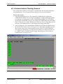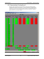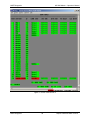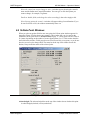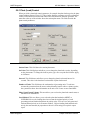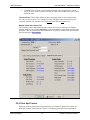
1
MC3000 MASTER CONTROL SYSTEM OPERATOR’S MANUAL MC3000 – Operator’s Manual MSE-Tetragenics MC3000 Master – Operator’s Manual © MSE-Tetragenics 1999, 2000, 2004, 2006, 2007, 2008 Document Version 3 MC3000 System Version 15 MSE-Tetragenics Phone: 406-533-6800 Fax: 406-533-6818 www.tetragenics.com MSE Phone: 406-494-7100 Fax: 406-494-7230 http://www.mse-ta.com/ Printed in the U.S.A. The contents of this manual and the associated MSE-Tetragenics software/hardware are the property of MSE Technology Applications Inc., MSE-Tetragenics department. For additional copies of the software/hardware, please contact MSE-Tetragenics. All product names are the registered trademarks or trademarks of their respective manufacturers. The information in this document is subject to change without notice. MSE-Tetragenics assumes no responsibility for any errors that may appear in this document. Software License Notice – the software described in this document (if any) is furnished under a license and may be used or copied only in accordance with the terms of such license. The information in this document has been carefully checked and is believed to be entirely reliable. For more information, contact MSE-Tetragenics or visit our web site at www.tetragenics.com. We are constantly improving our documentation. If you have suggestions or comments concerning this document, please send them to Technical Publications, care of MSE-Tetragenics. ii MSE-Tetragenics MC3000 Master – Operator’s Manual Table of Contents CHAPTER 1 INTRODUCING THE MC3000 MASTER CONTROL SYSTEM ...............................1 1.1 1.2 1.3 1.4 1.5 Standard Components/Options........................................................................................................ 2 1.1.1 Software Features................................................................................................................... 2 1.1.2 Options.................................................................................................................................... 3 Features Quick List .......................................................................................................................... 3 System Interface .............................................................................................................................. 5 What’s Covered in this Manual ........................................................................................................ 5 What's Not Covered in this Manual.................................................................................................. 5 CHAPTER 2 STARTING THE MC3000 ..............................................................................6 2.1 2.2 2.3 2.4 Files Required .................................................................................................................................. 6 View the MC3000 System Using WTV ............................................................................................ 7 2.2.1 Log into the System via WTV.................................................................................................. 8 2.2.2 Navigating around a System Screen in WTV ......................................................................... 8 Setting up an Edit Station to Edit the Database............................................................................... 8 Installing MC3000 Master Code....................................................................................................... 9 CHAPTER 3 WORKING WITH THE MC3000 ....................................................................10 3.1 3.2 Interface Overview ......................................................................................................................... 11 3.1.1 Communications and Alarm Status Fields............................................................................ 12 Communication Status................................................................................................................ 12 Alarm Status ............................................................................................................................... 12 3.1.2 Function Keys ....................................................................................................................... 13 Mouse Buttons ............................................................................................................................ 13 General Functions Keys and Selections..................................................................................... 13 Other Keyboard Functions Available .......................................................................................... 14 Overview of Points and Override Values ....................................................................................... 17 3.2.1 Digital Points ......................................................................................................................... 17 3.2.2 Analog Points ........................................................................................................................ 17 3.2.3 N-State .................................................................................................................................. 17 3.2.4 Override Values .................................................................................................................... 17 CHAPTER 4 MC3000 MAIN SCREENS ...........................................................................19 4.1 4.2 4.3 4.4 4.5 System Status Screen.................................................................................................................... 19 4.1.1 Custom Graphic System Status Screen ............................................................................... 19 4.1.2 Auto-Generated System Status Screen................................................................................ 20 Communications Tracking Screens ............................................................................................... 25 4.2.1 Communications Tracking Screen 1 ..................................................................................... 26 4.2.2 Communications Tracking Screen 2 ..................................................................................... 27 4.2.3 Overview ............................................................................................................................... 29 System Alarms Screen................................................................................................................... 30 4.3.1 Navigating through the Alarms.............................................................................................. 31 4.3.2 Acknowledging Alarms.......................................................................................................... 31 4.3.3 Deleting Alarms from the Screen .......................................................................................... 31 Alarm Screen Lists and Filter Times........................................................................................... 31 Alarm Queue Filter Time............................................................................................................. 32 RTU Screen Select ........................................................................................................................ 32 Site Specific Screens ..................................................................................................................... 35 iii MSE-Tetragenics MC3000 Master – Operator’s Manual CHAPTER 5 MC3000 FEATURES ..................................................................................39 5.1 5.2 5.3 5.4 5.5 5.6 5.7 5.8 Error Messages.............................................................................................................................. 39 Selecting Parameters or Entering Numeric Values in Update Windows ....................................... 40 Accessing Station Information ....................................................................................................... 40 Analog Point Windows ................................................................................................................... 42 Digital Point Windows .................................................................................................................... 48 N-State Point Windows .................................................................................................................. 51 Control Windows ............................................................................................................................ 54 5.7.1 Discrete Control .................................................................................................................... 55 5.7.2 Sequential Control ................................................................................................................ 57 5.7.3 PID Control............................................................................................................................ 57 5.7.4 Analog Output Control .......................................................................................................... 60 Plant Control Windows................................................................................................................... 62 5.8.1 Plant (Load) Control .............................................................................................................. 63 5.8.2 Generator Control ................................................................................................................. 64 5.8.3 Plant Spill Control.................................................................................................................. 72 5.8.4 Spill Gate Control .................................................................................................................. 74 5.8.5 Pond Control ......................................................................................................................... 76 5.8.6 Excitation Control .................................................................................................................. 78 CHAPTER 6 USING EPRINTER (ETHERNET PRINTER) ......................................................84 CHAPTER 7 THE MC3000 MASTER HOME PAGE ...........................................................87 7.1 7.2 Requirements for the Home Page .................................................................................................87 Viewing the Home Page................................................................................................................. 87 CHAPTER 8 SYSTEM MESSAGES ..................................................................................91 8.1 8.2 8.3 8.4 8.5 8.6 8.7 Program Diagnostic Messages ...................................................................................................... 91 8.1.1 Startup Progress Messages.................................................................................................. 91 8.1.2 Error Messages..................................................................................................................... 92 8.1.3 Warning Messages ............................................................................................................... 92 WTV Window Messages ................................................................................................................ 92 Four 11 / Master Messages ........................................................................................................... 93 Nine 11 Messages ......................................................................................................................... 93 Alarm/Status Messages ................................................................................................................. 94 Informative Messages .................................................................................................................... 95 Control Messages .......................................................................................................................... 95 Control Tag Changes ..................................................................................................................... 95 PID Numeric Parameter Changes ................................................................................................. 96 Analog Limit, Hysteresis, Exception Deadband Changes ............................................................. 96 Analog Alarm Level Changes ........................................................................................................ 96 Digital Alarm Level Changes.......................................................................................................... 96 Digital Filter Changes..................................................................................................................... 96 Override Messages ........................................................................................................................ 96 Flash Enable/Disable Messages.................................................................................................... 97 WWVB Messages .......................................................................................................................... 97 INDEX .........................................................................................................................99 iv MSE-Tetragenics MC3000 Master – Operator’s Manual List of Figures Figure 1. MC3000 Example Block Diagram.................................................................................................. 2 Figure 2. Screen Hierarchy Functional Diagram......................................................................................... 10 Figure 3. Auto-Generated Screen Layout ................................................................................................... 11 Figure 4. Custom Graphic System Status Screen ...................................................................................... 20 Figure 5. Auto-Generated System Status Screen ...................................................................................... 21 Figure 6. Set New Time .............................................................................................................................. 22 Figure 7. System Reports Window ............................................................................................................. 23 Figure 8. Security Window .......................................................................................................................... 23 Figure 9. Load Database Window............................................................................................................... 23 Figure 10. Comm Track Select Screen. From this screen, select a port to display its tracking screen...... 25 Figure 11. Comm Track Screen 1............................................................................................................... 26 Figure 12. Comm Track Screen 2............................................................................................................... 28 Figure 13. System Alarms Screen .............................................................................................................. 30 Figure 14. System Alarm Filter Window...................................................................................................... 32 Figure 15. RTU Screen Select Screen........................................................................................................ 33 Figure 16. Graphic Screen Select Screen .................................................................................................. 34 Figure 17. Site Screen - Points ................................................................................................................... 36 Figure 18. Site Screen - Controls................................................................................................................ 37 Figure 19. Custom Site Screen................................................................................................................... 38 Figure 20. Station Information Window....................................................................................................... 41 Figure 21. Analog Point Window................................................................................................................. 43 Figure 22. PID Control Window .................................................................................................................. 46 Figure 23. Example of Limit States Showing Hysteresis ............................................................................ 47 Figure 24. Digital Point Window.................................................................................................................. 48 Figure 25. N-State Point Window................................................................................................................ 51 Figure 26. Control Start Window................................................................................................................. 53 Figure 27. Associated Controls Window ..................................................................................................... 54 Figure 28. Discrete Control Window ........................................................................................................... 55 Figure 29. Sequential Control Window ....................................................................................................... 57 Figure 30. PID Control Window .................................................................................................................. 58 Figure 31. Analog Out Control .................................................................................................................... 61 Figure 32. Plant Control Window ................................................................................................................ 63 Figure 33. Generator Window - Status ....................................................................................................... 65 Figure 34. Voltage Regulator from Generator............................................................................................. 66 Figure 35. Synch Parameters Window ....................................................................................................... 67 Figure 36. Generator - Ratings and Parameters......................................................................................... 70 Figure 37. Generator - Vibration ................................................................................................................. 71 Figure 38. Generator - Related Points and Controls .................................................................................. 72 Figure 39. Plant Spill Control ...................................................................................................................... 73 Figure 40. Spill Gate Control Window......................................................................................................... 74 Figure 41. Pond Control .............................................................................................................................. 76 Figure 42. Voltage Bus – Status Area......................................................................................................... 79 Figure 43. Voltage Regulator from Bus....................................................................................................... 80 Figure 44. Voltage Bus – Ratings and Parameters Area............................................................................ 82 Figure 45. Voltage Bus - Related Points and Controls Area....................................................................... 83 Figure 46. Eprinter Main Window................................................................................................................ 84 v MSE-Tetragenics MC3000 Master – Operator’s Manual Figure 47. Eprinter Host Select................................................................................................................... 85 Figure 48. Eprinter Number of Lines........................................................................................................... 86 Figure 49. Eprinter Font Window ................................................................................................................ 86 Figure 50. MC3000 Home Page ................................................................................................................. 88 Figure 51. Home Page RTU/IED List - Top ................................................................................................ 89 Figure 52. Home page RTU/IED List - Bottom............................................................................................ 90 Figure 53. Error Message Window ............................................................................................................. 92 Figure 54. WTV32 Override Message ........................................................................................................ 92 vi MSE-Tetragenics MC3000 Master – Operator’s Manual CHAPTER 1 INTRODUCING THE MC3000 MASTER CONTROL SYSTEM W elcome to the MSE-Tetragenics MC3000 Series Master Control System. The MC3000 Master lets you monitor and control the input/output points via a remote unit. The base system is compact but expandable to include a wide variety of options. It runs on Windows for a PC based Master or VME Linux for a G-series Plant Control System (PCS). The manual applies to both types of systems in most cases; the main difference being that the VME-based PCS has no hard drive (disk). Both systems are referred in this manual to as an MC3000 Master. Any differences or exceptions are noted. The MC3000 Master gives you power, flexibility, and an easy interface. It uses the capabilities of today's powerful personal computers and operating systems and combines advanced MSE-Tetragenics software processing for maximum system performance. This gives you a cost-effective Master with enhanced reliability, a simple configuration, and an overall system that is reliable, fast, and easy to use. The system also provides Ethernet capabilities and can interface to your network or the Internet (World Wide Web). The MC3000 Master can be single or hot-standby dual configured. It supports Ethernet and multiple serial ports using intelligent multi-port boards. And the Master can poll 10,000 or more remote sites. You can easily add, change, or delete peripheral devices or polling ports using the System Database Editor. The graphic user interface WinTetraVision (WTV) provides access to the Master for up to 32 users via serial, Ethernet, or dial-up connections. And an Internet interface lets you view your system over a built-in, customizable web page. The Master is a platform for communicating with Remote Terminal Units (RTUs), Plant Control Systems (PCSs), Intelligent Electronic Devices (IEDs), Programmable Logic Controllers (PLCs), and other peripheral devices including other masters through Ethernet or serial ports connected to communication links (for example, hardwires, modems, or microwave radios). The figure on the next page shows a simplified example hardware diagram of an MC3000 system. MSE-Tetragenics 1 Chapter 1 Introducing the MC3000 MSE-Tetragenics MC3000 Master – Operator’s Manual Figure 1. MC3000 Example Block Diagram 1.1 Standard Components/Options The Master ships with the following hardware and software components • • • • • • • • PC Windows or VME-based platform Windows (PC-based) or Linux (VME-based) operating system MC3000 Monitoring/Control Software 1-year warranty for MSE-Tetragenics produced hardware and software Support for up to 32 GUI display devices (WTV) Support for 10,000 or more sites per system User Documentation Options (see Options list) 1.1.1 Software Features • • • • • MSE-Tetragenics Ethernet Functionality (Telnet, GUI) Internet Viewing via Standard Homepage Auto-Generated Screens Diagnostics Telnet Port (PC-based) Electronic Printing (Eprinter) 2 • • • • • Global Daily Log File (PC-based) History Files -1 per site (PC-based) Pop-Up Windows Online Parameter Changes Communications and Alarm Status Chapter 1 Introducing the MC3000 MSE-Tetragenics MC3000 Master – Operator’s Manual • • • • • • • • • Multiple Download Capabilities Dial-up RTU support Automatic Reports Multi-Region/Number Callout Protocol Support (Modbus, DNP3.0, & more) Sequential Control Trending – Instant & Historical Easy Alarm Recognition SCADA Functions • Communications Tracking/Statistics • Alarm Filter Lists • Animated Graphics • PID control • Password Protection • Audible Alarms • Ping Capabilities • Fast Booting • and more 1.1.2 Options The MC3000 is available with a variety of options to increase system functionality and meet your requirements. Your system may contain any or all of the options listed. • Dual Hot Standby Masters • System Database Editor (SDE) Software • 19" rack mount or desktop systems (PCbased) • Laptop Master Test Set software • Dial-Up RTU Polling • Dial-up GUI WTV Workstations • Disk media options (PC-Based) • Expandable RAM • Multiple alarm and report printers • Alarm call-out capability • Critical Alarm Upgrading for Callout or control • UPS system • Time Synchronization • Serial port expandability (RS-232) using intelligent multi-port boards 1.2 Features Quick List > When you add new sites to the database, the MC3000 Master system can communicate with thousands of remote sites. Creating screens for each site (listing each point you want monitored for each RTU) could be very time consuming if you had to do it manually. Fortunately, the MC3000 automatically generates screens for sites as they are entered into the database. It generates a text System Status Screen, Site Select Screens, and Site Screens. Depending on your system and the information you enter into the database, the system can generate the new screens according to site, region, or other group identifier. Once you load the new database into the Master, you can access screens for the all sites immediately. > Pass-thru logging Using WTV GUI terminal and local printer or disk. Automatic screen generation > The system can update alarms to critical after a Automatically update alarm levels programmable elapsed time on a per point basis. (option) Use the one-port Test Set [for laptops] for onsite installation MC3000 Test Set software (optional) and diagnosis of remote installations. The Test Set allows you to set up and test new installations unassisted by the > command center, poll remote sites, display points, and use local controls. MSE-Tetragenics 3 Chapter 1 Introducing the MC3000 MSE-Tetragenics MC3000 Master – Operator’s Manual Serial > communications analyzer functions To help you analyze serial data passed between two computer-based devices. Telnet Spy helps to monitor and troubleshoot communications between two devices. (Available on PC-based systems.) > Network access Network access to WTV GUI color graphics terminal using TCPIP protocol. > Network editing Network editing on Windows workstations. > Network downloads Download the database or individual files from the Edit Station to the Master. > Internet / Intranet home page On your built-in home page, display values, alarm conditions, alarm levels, reports, history and log files. > TELNET attachment Remote re-booting of the Master. > User configurable ports Add or delete a polling port and work with different protocols. Dynamic Link Library support (DLLs) For added functionality: Create add on modules (using Borland's C++ compiler) to add unique protocols, reports, etc. (or you can have MSE-Tetragenics create the modules). Implement protocols; interact with the online database; or communicate serially or talk TCP/IP, UDP, ICMP/IP over Ethernet. You can use this extensibility to expand your system to meet unique needs –in real-time. Dial-up Graphical > User Interface support Using WTV and a modem to access the Master via telephone lines. > > Single or dual systems > Downloadable RTUs > Alarm beep tones The Master supports MSE-Tetragenics TG332 downloadable RTUs. Define an alarm level to kick off the critical beep tones on the system speakers. Restore features Save the values of all the points when you exit the MC3000. When you reboot, all the values are restored to previous levels unless the point no longer exists or is now a different type. The program also saves the alarms on the system alarm screen so that they are restored after a reboot. Printing features Print system messages and save them to daily log files. > Customized printout features Print alarms in different fonts or place spaces around the messages for easy viewing. > Automatic timebased features Save your database or perform a complete poll periodically to safeguard information. > MSE-Tetragenics Available 4 Chapter 1 Introducing the MC3000 MSE-Tetragenics MC3000 Master – Operator’s Manual 1.3 System Interface The MC3000 outputs and receives operator information through a variety of media such as those listed below. You access/view the system through a workstation running the WTV program or via the Internet/Intranet (with proper access and authorization). You can edit the database and system parameters using an editing station with access to the System Database Editors (SDE). These programs can execute on local or remote machines or the same machine. • Operator WTV workstations display color graphics screens and allow input through a • • • • keyboard and mouse. Operators use the WTV to monitor the system status, initiate controls, and load new database files. The system logs alarm messages, control messages, and on-line changes and sends reports to printers, Eprinter, and/or disk. Field operators communicate with the MC3000 via WTV over Ethernet or through an optional remote dial-in port. An auto callout option dispatches maintenance personnel to repair critical system malfunctions. You can view your system using the Internet/Intranet via WTV or the built-in web page. 1.4 What’s Covered in this Manual This manual introduces you to the MC3000 Master Control system and shows you how to access and use it. It assumes you are familiar with your computer system, general Windows operating system functions, and have access to the manuals referenced in this document. The manual includes the following: • quick instructions on how to start the MC3000 system, • descriptions of common features, • password capabilities, • examples of general screens, • procedures to change parameters and points, • instructions on how to generate reports, and • information on system messages, alarm severity information, and options. 1.5 What's Not Covered in this Manual This manual is written for an operator and assumes that the MC3000 system is loaded on the Master computer. Complete installation procedures are not covered in manual. The manual assumes that the operator has a good knowledge of working in a Windows environment. Also, for specific instructions on installing and configuring the WTV see the MSETetragenics WinTetraVision 32 (WTV32) Graphical User Interface Workstation User Manual. MSE-Tetragenics 5 Chapter 1 Introducing the MC3000 MSE-Tetragenics MC3000 Master – Operator’s Manual CHAPTER 2 STARTING THE MC3000 MC3000 is designed to be user friendly, but a general idea of how the program works will help you get started. The MC3000 is the backbone of the control system. It lets you control your system. Other programs interface with the MC3000 to allow you to change the database and download the changes (System Database editors (SDE)) and view the system using WTV installed on a local or remote PC. Refer to the manuals provided with your system. 2.1 Files Required The required program files are loaded on the PC-based Master computer when you get your system or supplied on a CD. Below is a list of files (executable, database, dll files, etc.) that are generally present in your run time directory when you start the PC based program. Other files may be present depending on your system options. • • • • • • • • • • • • • • • • • MC3000W.EXE MCWSTART.EXE TABLE.BIN DATA.BIN Tsk_htty.dll Tsk_httn.dll Add_tnet.dll License.dll Dllmgr.dll Add_rpar.dll Add_eprt.dll Add_stxt.dll Sitedata.tdb Sitedata.tix Almfltr.dat Alrmque.dat *.str files • • • Homepage.htm Port.cfg WTVinfo.dat MC3000 main program MC3000 startup program Binary database table Binary database data Password ‘on’ for HTTP server OR Password ‘off’ for HTTP server Enables Telnet code Holds licensed point count Manages the dll files Enables custom reports Enables the Eprinter virtual printer Enables access to site data screens Site Data file containing the site names and data Site Data file containing an index to sitedata.tdb File to hold site Alarm Filter Lists File to hold current System Alarm Screen records Files to hold analog, digital, and n-state point values – stored upon normal shutdown and restored on MC3000 boot-up Browser home page Port configuration file Compressed file containing screen files (s*.scr, *.set, and *.lib) for use by the WTV graphical user interface program The MC3000W run time sub-folders hold the following: • \graphics • \cgi_bin • \syshtml MSE-Tetragenics Holds header information for the auto-generated web pages Holds Java utilities for help, time, and eprinter (jar files) Holds default web page file: homepage.htm. Sub-folders named with the station text contain optional site web files 6 Chapter 2 Starting the MC3000 MSE-Tetragenics MC3000 Master – Operator’s Manual • \XML • \Archive • \AUDIT • \seqvals • \Rep Holds XML files as necessary: archive.xml, dllconf.xml, and system.xml. Must exist for the Download manager utility Holds daily archive files used for historical trending. The format is set up in the archive.xml file in the XML folder Hold daily files used to store WTV32 user information (folder created by the MC3000) Holds values that can be optionally stored and accessed via sequential control (folder created by the MC3000) Holds custom report template files The following folders are set up in the database with the MiscData Editor as necessary: • • • • • \LOG \ALM \CHG \OPR \REP Holds daily log files containing all printer messages and alarms Holds the *.ALM site specific alarm files Holds the *.CHG site specific parameter change files Holds the *.OPR site specific executed controls files Holds the *.REP site specific reports sent to disk files As the MC3000 PC-based program starts, it reads an ASCII file called PORT.CFG (port configuration file) and initializes the ports and online features according to the information in the file. PORT.CFG contains a listing of the available software interfaces and their designated hardware ports (that you specify using the SDE). PORT.CFG must reside in the database directory as well as the run time directory. 2.2 View the MC3000 System Using WTV To view your system from a local or remote machine, start the MC3000 program and then use the WTV graphical interface program to view the system screens. Using WTV you can connect to the Master using an Ethernet, serial, or dial-up link. If it is not already installed, install the WTV software. Refer to the WinTetraVision 32 (WTV32) Graphical User Interface Workstation User Manual. When you connect the WTV to the Master, the Master sends the necessary screen files to the local machine to display the screens. To start the MC3000 and use WTV from a Windows environment (if you are at a Windows workstation with WTV installed), follow the general steps below. Window and menu examples appear in detail in the next chapter. 1. From the Windows Start button, Windows Explorer, or using a desktop shortcut icon, run the MCWSTART.EXE file. This starts the MC3000 program. An MC3000 window appears listing the status of the system start up. When it is finished, the window will show the date/time and MC3000W Version XX.XX.XXX IS ACTIVE, where XX.XX.XXX stands for the software version. 2. Open the program group that contains the WTV program and double click the WTV program icon (or double click a desktop shortcut). The WTV window appears. 3. From the WTV window toolbar, select File> Open Host. The Open Configuration window appears. MSE-Tetragenics 7 Chapter 2 Starting the MC3000 MSE-Tetragenics MC3000 Master – Operator’s Manual 4. Select a host to open (or create a new one) and click OK. The system will connect to the Master, load the files, and the main system screen for that host configuration appears. Refer to Chapter 3 Working with the MC3000 and Chapter 4 MC3000 Main Screens for details on working with the system and descriptions of the screen fields. 5. Log into the system. See Log into the System via WTV below. 2.2.1 Log into the System via WTV Password protection functions in the MC3000 provide system security. Each password has an associated user name and access level. The access level determines the functions and points a user can access. If you do not log into your system, you can view screens but may not be able to change parameters. In some systems you may not be able to view screens. Contact your system administrator for your user name and password. Log into the System: Refer to Logging In and 1. From any WTV screen, press <Shift>F8 (or the initialized log in key or text for your system). A security window appears asking for user name and password. Logging Out <Shift> F8 on 2. Enter your user name, password, and timeout time (in minutes). Your access stays in page 15 for effect until you relinquish it; otherwise, it automatically times out after the period you more specify. If initialized for your system, use a timeout time of 0 for no timeout. information on passwords and 3. Click Log In. You are logged in. You have access until you log out or your time-out time expires. access levels. 2.2.2 Navigating around a System Screen in WTV Using WTV, all MC3000 screens are accessible using function keys or poke points (initialized text or symbols that link to other screens or functions). The starting point is the main System Status Screen. From there, you navigate to other screens in the system. To navigate to other screens or pop up windows: 1. Select or press an assigned function key. 2. Select an initialized poke point (text or symbol). This can be a word or symbol on the screen that acts as a button. It can be flashing. Clicking the word/symbol displays the corresponding screen or pop-up window. 2.3 Setting up an Edit Station to Edit the Database An Edit Station differs from a WTV workstation in that it contains the SDE suite of editors that allow you to change the system settings. An edit station can be local or remote and also act as a workstation. Use an edit station to edit the Master database. See the steps following. Contact your system administrator for information on editing the database. If the Edit Station is attached to a Local Area Network (LAN), you can access and use the SDEs via any Windows machine with the proper network passwords. You assign/map the edit station as a network drive resource. The remote workstation will then function as if it was the local keyboard. Alternately, you can install the SDE suite on an existing network server for easy access. MSE-Tetragenics 8 Chapter 2 Starting the MC3000 MSE-Tetragenics MC3000 Master – Operator’s Manual Note: Using the LAN access features can be slower than directly accessing the program at the Edit Workstation because of varying network traffic conditions occurring during a normal workday. For an Edit Station connected locally to the Master, you can still use the network for the upload between Edit Station and Master. If a network interruption occurs between the Master and the Edit Station, you can alternately transfer the database using a CD. Note: Always back up your working database files prior to any edit session to assure recovery in the event of a faulty upload or database errors. You can conduct only one edit session at a time. Coordinate with edit personnel on the network to prevent multisession editing. To use the Edit Station over a LAN, set up the edit station as follows: On a Windows operating system: 1. Establish the Edit Station machine as a network drive resource (map it). 2. Set up network TCPIP addresses in Control Panel (network functions.) 3. Set a network password (optional). 4. Enable file sharing. 2.4 Installing MC3000 Master Code MSE-Tetragenics generally ships the MC3000 Master and G-series PCs with the code installed. However, if you need to install a new program use the steps below: Hint: Always make back up copies of existing files before installing new ones. 1. Copy the new code executable files to the MC3000 run time directory; for a PCS use the SDE Data Manager to send the files. 2. Restart the MC3000 or PCS. 3. Use the SDE Data Manager to send a new database if necessary. Refer to the System Database Editor (SDE) user manuals for more information on databases. To load a new database, refer to Figure 9 on page 23. MSE-Tetragenics 9 Chapter 2 Starting the MC3000 MSE-Tetragenics MC3000 Master – Operator’s Manual CHAPTER 3 WORKING WITH THE MC3000 The MC3000 program and screens contain many standard features and function keys. Working in the Windows environment via WTV, the system supports standard Windows features. Refer to the Windows information supplied with your computer. The MC3000 user interface WinTetraVision WTV is based on a hierarchical system of autogenerated screens and custom graphic screens. As the operator, you use the screens to see system status and perform or access specific functions or information. Understanding the hierarchy and the relational paths between the auto-generated screens gives you a better understanding of the overall system and how it works. The functional block diagram (shown below) shows a general road map of the MC3000 screen hierarchy. System Status Screen COMM Tracking Help Screen System Report Window Security Login/ Logout Window Master/ RTU Select Screen Time Set Window System Alarms Master or RTU Screen Next Screens Save Database to Disk Station Report Window Figure 2. Screen Hierarchy Functional Diagram MSE-Tetragenics 10 Chapter 3 Working with the MC3000 MSE-Tetragenics MC3000 Master – Operator’s Manual 3.1 Interface Overview The WTV provides a GUI that lets you view your system and set parameters all within the familiar Windows environment. Menus and pop up windows are consistent with Windows functionality. Each screen also contains keyboard shortcuts for various commands and features. Figure 3 shows the general layout of the MC3000 auto-generated screens and an inset box detailing what the specific areas represent. Refer to your Windows documentation for information on working with windows in general. Refer to the WinTetraVision 32 (WTV32) Graphical User Interface Workstation User Manual for information on the WTV installation and configuration. The layouts of the auto-generated screens are similar. The current host shows at the top of the window; the day, date, and time (in 24-hour format) appear in the lower right-hand corner of the screen; the system name and screen title appear in the top center; and alarm status appears in the lower right corner. The display area and data change area take up most of the middle section screen, while the bottom portion of the screen lists initialized function keys or text, and system prompts. The function keys and initialized text areas are usually self-explanatory. For every operator action performed from the WTV screens, the system sends a corresponding message to the main printer and daily log file. Figure 3. Auto-Generated Screen Layout MSE-Tetragenics 11 Chapter 3 Working with the MC3000 MSE-Tetragenics MC3000 Master – Operator’s Manual To select data / parameter fields or initialized functions (text): With the cursor, select (click) the text or point. To use the function or initialized keys: Press the function key (F1, F2, etc) OR With the cursor, select (click) the function key text. When you select or press a function key, the initialized screen appears or the key initiates a function. When you select a data point or control update field, a corresponding pop-up window appears. These windows let you initiate control functions and change data and system parameters (depending on your password level). Each window contains an Ok button (to process the change) and a Cancel button (to cancel the changes). You access the pop-up update windows from any screen that displays analog, digital, control, or system update data. Hint: The window and screen examples shown throughout this manual are intended to show general features. They may or may not replicate actual screens. 3.1.1 Communications and Alarm Status Fields Communication Status The field at the top of site-specific screens shows communications status for that remote site. The communications status appears at or below the remote site screen level on autogenerated screens. The communication status is a multiple state (n-state) update that can be initialized to appear on any custom system screen. The system can send a communication update status to any or all alarm destinations depending on initialization (for example, the System Alarm Screen, a printer, or the log file). The list below defines the communications status text that appears in the update field. The specific text may vary according to initialization. Communications Normal: The master and the remote site are communicating properly. Communications Failed: The Master and the remote site are unable to communicate properly. Either the communications equipment has failed or the device at the remote site in no longer operating. Communications Hdfail: The MSE-Tetragenics device at the remote site has experienced a hardware failure: one of the site’s input/output boards failed to respond to a poll. Communications Disabled: The operator at the Master has disabled communications with the device at the remote site by changing the polling frequency to zero. Alarm Status The alarm status appears on lower right to the left of the data/time on every screen as the word ALARMS in colors as per customer specifications. The ALARMS text color changes to reflect the highest severity level of all alarms present in the system, for example red for communications failure: ALARMS. Usually, when there are no alarms, the word ALARMS is green. If the word ALARMS is flashing, this means that the operator has not acknowledged one or more alarms or state changes in the system. For easy reference, the MSE-Tetragenics 12 Chapter 3 Working with the MC3000 MSE-Tetragenics MC3000 Master – Operator’s Manual ALARMS color code is the same as used for the station symbols on the System Status Screen. 3.1.2 Function Keys As an operator, you use the mouse and function keys (and poke point areas) extensively. The function key and mouse button definitions can change with the various screens and levels of execution. Functions can also appear as key prompts (F1) or poke points (text or symbols), depending on your set up. Your system administrator can define special keys or options. On auto-generated screens refer to the two bottom lines of each screen for the current definitions. On custom graphic screen the function key definitions may be initialized on any area of the screen as desired. Other common functions are available on all screens, but may not be listed at the bottom. The lists below give brief descriptions of default function keys and corresponding mouse buttons, and common keys not usually defined at the bottom of each screen. Mouse Buttons The following function keys perform like mouse buttons. For example, to display a screen associated with a site/RTU symbol, place the cursor on the symbol and either press the left mouse button or press the F4 function key. Function Key Mouse Button F4 Left F5 Middle F6 Right Hint: Your mouse may not be set up to use the middle button. In this case select the function/symbol with the cursor and press the F5 key. General Functions Keys and Selections The list following shows the default function keys and selections (poke points) available on different screens. The descriptions listed here represent a general system. Your system may be set up differently. Except for the F4, F5, and F6 keys you can set different keys to represent different functions on custom graphic screens (refer to the System Database Editor Manual). For auto-generated screens, the system sets up the function keys. Some keys display system screens. Refer to the individual screen descriptions for information on screens and for general functions available on those screens, for example the System Alarms Screen. Hint: The function key designation may change for your system, but the function definition will remain the same. For example, whether your system uses F1 or another key, the Silence function will still silence the audible alarm. Because the functions are context sensitive, corresponding functions appear only on relevant screens. For example, the F2-Site Info key will appear on the site-specific screens, while the F3- Acknowledge key may appear on any screen. Look on individual screens for definitions of available keys. F1- Silence F2- Comm Track F2- Site Info F3- Acknowledge MSE-Tetragenics Silences the audible alarm. Displays the Communications Tracking Screen. Displays site specific text information (optional). Acknowledges all unacknowledged (flashing) alarms. 13 Chapter 3 Working with the MC3000 MSE-Tetragenics MC3000 Master – Operator’s Manual F3- Ack All Com F4- Sel Left F4 – Sel RTU F5- Sel Middle F5- Comm DLG F6- Sel Right F6- Ack Comm F7- Next Screen Shift F7 Previous F8- Sys Alarms F8- Report F9- Up One Lvl F10- Exit or EXIT System Reports Acknowledges all communications alarms. Selects the area on the screen designated by the cursor and corresponds to the left mouse button. Select the site/RTU screen designated by the cursor and corresponds to the left mouse button. Selects the area on the screen designated by the cursor and corresponds to the middle mouse button. Displays a site window with choices specific to the site designated by the cursor and corresponds to the middle mouse button. Selects the area on the screen designated by the cursor and corresponds to the right mouse button. Acknowledges the communications status of the site designated by the cursor and corresponds to the right mouse button. Displays the next screen in a loop. Displays the previous screen in a loop. Displays the System Alarms Screen. Display a window that lets you select a report to generate: either a system report or a report specific to the site whose screen is currently displayed Displays the previously displayed screen above the level of the current screen/loop. Returns to the System Status Screen that is displayed on system boot-up. Displays a window that lets you select system reports to generate. Other Keyboard Functions Available Toggling the Communications Alarm Filter (<Delete> Key): The <Delete> key toggles the state of the communications alarm message filter. On systems with remote sites (for example, RTUs), the filtered/not filtered status of the communications alarm message appears on the auto-generated Text System Status Screen (Comm Filter Status) as Enabled or Disabled. You can change the status from that screen or use the <Delete> key from any screen (depending on your system configuration). • For filtered communications alarms, press <Delete>. The system logs communications messages to the printer only when that status is acknowledged (not flashing) when the change in communications status occurs. This assures that the system logs a new unacknowledged communications alarm even when filtering is enabled. • For not filtered communications alarms, press <Delete> again. When these alarms are not filtered, the system logs all communications alarm/normal messages to the printer. To toggle the status from the Text System Status Screen, move the cursor over the Comm Filter Status field and click. The field changes between Enabled and Disabled. MSE-Tetragenics 14 Chapter 3 Working with the MC3000 MSE-Tetragenics MC3000 Master – Operator’s Manual Toggling the Audible (Annunciator) Alarm (<End> Key): The <End> key toggles the enable/disable status of audible alarms (annunciator). The status appears on the auto-generated Text System Status Screen (Annunciator Status) as Enabled or Disabled. You can change the status from that screen or use the <End> key from all the screens, depending on your system configuration. The enable/disable status pertains to both levels of the annunciator (non-critical and critical). When this field shows Disabled, both annunciators are disabled. To disable the audible alarm, press <End>. To enable the audible alarm, press <End> again. To toggle the status from the Text System Status Screen: move the cursor over the Annunciator Status field and click. The field changes between Enabled and Disabled. Toggling the Auto Report Status: The Auto Report Status appears on the auto-generated Text System Status Screen as Enabled or Disabled. You can change the status from that screen. To toggle the status from the Text System Status Screen: move the cursor over the Auto Report Status field and click. The field changes between Enabled and Disabled. When this status is enabled, the system will generate all reports initialized to occur automatically at specific times. When this status is disabled the system will not generate the reports. Changing the Default Home Screen (<Home> Key): Press the <Home> key (or assigned function key) to toggle the display between two screens you use frequently in the system. On boot-up, the default Home Screen is the main System Status Screen. When you access another screen and press <Home> (or assigned function key), the screen currently displayed becomes the new Home Screen and the previous Home Screen appears; if you select the Home function again, the previous Home Screen appears, etc. This way you can flip easily between two screens. Logging In and Logging Out (<Shift>F8): Password protection in the MC3000 Master provides secure lockout of customer functions and parameters. Each password has an associated user name and access level. The access level determines the functions and points a user can access. If you do not log into your system, you may not be able to change parameters and may be prohibited from even viewing some screens. Log in or log out from any screen in the Master by pressing the <Shift> and F8 keys simultaneously (or clicking the initialized log in or security button if the screen contains one). Contact your system administrator for your user name and password. Passwords are assigned or changed in an offline edit session. Contact your system administrator or refer to System Database Editor – Password Editor manual for instructions on setting passwords. Logging Into/Out of the System 1. Press <Shift>F8. A window appears asking for information. 2. Enter your user name, password, and timeout time (in minutes). Your access stays in effect until you relinquish it. Otherwise, it automatically times out after the period you specified. Logger messages contain the user name and timeout value you enter. 3. Click Log In (or Log Out if you are logging out). The program assigns the access level associated with your password to the graphics/editing workstation from which you entered the password. Until you relinquish access using the same password, that workstation keeps your access level. You can execute all the functions MSE-Tetragenics 15 Chapter 3 Working with the MC3000 MSE-Tetragenics MC3000 Master – Operator’s Manual that are assigned this or a greater level. When you successfully log in, a logger message prints listing the date and time and the user name associated with the password. A corresponding message also prints when you log out. The user name prints each time the user gains or releases access. Access Levels The access level determines the functions and points that you can access from a terminal local to the computer or from a remote dial port. Remote dial ports have access to all functions and parameters available from a local port, depending on the access level associated with the operator password. Access levels can be any number between 0 and 255, with 0 the highest level of access. If someone has an access level of 0, they have access to all functions and points in the system when they enter their password. Each system defaults to an operator access level of 255 for each workstation it contains. When a user logs out, the device’s operator access level reverts back to 255. Only one user can be logged in at a time. If a new user logs in before a previous user logs out, the system automatically logs out the previous user. Any function or point within the entire database for the system can have an associated access level. The Master compares these access levels with the operator’s local access level to determine operator access. Password/Access Level Example The following example shows how the password program functions: The access level conditions include the following: Operators and Sequence John Smith has an access level of 3. He logs onto workstation device #1. Ellen Jones has a level of 5. She logs onto workstation device #2. Ralph Willis has a level of 7. He logs onto workstation device #2. The system automatically logs out Ellen Jones. Assigned Access Levels All analog point parameters in the system have been assigned an access level of 6. All control points have an access level of 4. All online reports functions have an access level of 7. On device #1, under the conditions above, all operators can perform functions (for example, analog/digital point parameter changes, control points, reports) until Smith relinquishes access on that device. All functions would be logged as being performed by Smith because he is the logged in user. Jones on device #2 has access to the analog point parameters but not the control points. When Willis logs in on device #2, that device reverts to level 7, which is assigned to Willis. Then, no operator on device #2 can change the parameters of analog points or execute control points. However, operators on device #2 can still request online reports. MSE-Tetragenics 16 Chapter 3 Working with the MC3000 MSE-Tetragenics MC3000 Master – Operator’s Manual 3.2 Overview of Points and Override Values The Master system receives and sends information through analog, digital, and n-state input points. The points are defined in files in the database. Your MSE-Tetragenics project manager and system administrator sets up the database. With proper access and using the WTV, you can then set and override the point values as necessary. The sections below give a brief description of the points. Refer to the System Database Editor manuals for detailed descriptions. 3.2.1 Digital Points In general terms, a digital point corresponds to the status of an electrical switch or contact closure (like a breaker). It is either on (energized) or off (de-energized). If the contact (switch) is open, then the digital point’s value is 0 (de-energized or open or off). If the switch is closed, then the point’s value is 1 (energized or closed or on). This analogy to a switch fails if you are discussing virtual (calculated) points. However, think of the value of the virtual point as either True (1) or False (0). Values for digital points come from either digital input circuit boards (polled point), Boolean processing instructions (virtual point), or from remote processors (polled or virtual). 3.2.2 Analog Points Analog point values come from analog input circuit boards, arithmetic processing instructions, or from remote processors. A polled analog point (in general terms) is an electrical signal that the system converts to engineering units. A virtual analog point’s value is calculated. The value is determined by various sources, conversions, or processing instructions. There are three numerical types of analog points: SHORT (16-bit), LONG (32bit), and Floating Point. They differ only in the size of the analog values each can hold. You can initialize analog points to have four out of range and one normal limit range. 3.2.3 N-State An n-state point is a multi-state point derived from two or three digital points. An n-state point derived from two digital points has 4 possible states. An n-state point derived from three digital points has 8 possible states. For example, a valve may require two sets of contacts to indicate its position: Contact 1 OPEN OPEN CLOSED CLOSED Contact 2 CLOSED OPEN OPEN CLOSED Position Valve is fully closed Valve is partially open or moving Valve is fully open Failure of indicating contacts 3.2.4 Override Values In the system you can override a digital, analog, or n-state input point to a set value. Digital inputs can be overridden to their contact open or closed state. Analog inputs can be overridden to any value between their absolute low and absolute high limits. An n-state point can be overridden to any one its initialized states. Refer to the individual sections for analog, digital, and n-state point update windows. MSE-Tetragenics 17 Chapter 3 Working with the MC3000 MSE-Tetragenics MC3000 Master – Operator’s Manual When a quantity is overridden, its value remains the same regardless of the actual state or value of the physical input. You can remove these overrides at any time. Overridden values appear on the system screens with a specific assigned color. This feature allows you to determine at a glance which quantities are overridden. A standard off normal report also includes the overridden quantities. The override feature is useful in various applications. If an input is malfunctioning, you can override it to prevent the system from reporting erroneous values. You can then use the input quantity in calculating other quantities that would be in error as a result of the faulty input. You can read an approximate analog value for the input and periodically change the override value to keep the calculated values within a reasonable range. Another application for overrides would be for a non-telemetered analog quantity, in other words a value not available from the remote site. An example of this would be a spillgate that you manually adjust by removing or replacing boards to adjust the spill. When you change the height of the gate, you can override the value of a virtual analog point to the new gate height. That value in turn can be used in total spill calculations. Another example application is for systems that monitor watt-hour and VAR-hour information. You can generate totals at a customer-specified rate (for example, daily, monthly, yearly) at a remote site and transmit them to the MC3000. If the site is powered down or if the monitoring equipment for these quantities becomes inoperative, the site cannot convey this information to the MC3000. Consequently, the totals at the MC3000 will not be current. To update these values, override the quantity to the correct value and remove the override. The value remains after you remove the override. All further information is added to this value. Hint: When you override a quantity at an MSE-Tetragenics remote device (PCS or RTU), it is actually taken off scan (not polled) in the device. MSE-Tetragenics 18 Chapter 3 Working with the MC3000 MSE-Tetragenics MC3000 Master – Operator’s Manual CHAPTER 4 MC3000 MAIN SCREENS MC3000 systems can use one or both of two types of screens: auto-generated and custom graphic. Auto-generated screens are initialized from the database by the Master on boot-up and contain entries for every point and control in the system. They require no effort beyond initializing the system database and if desired, changing the default colors for the various screen features. Custom graphic screens are initialized using the SDE’s Screen Generator and are completely customizable including colors, content, function keys/buttons and links to the auto-generated screens or other custom screens. The following sections show examples of both auto-generated and custom graphic screens. 4.1 System Status Screen The main System Status Screen is the header screen in the MC3000 system. It appears when you access the system from the WTV. The screen can appear in custom graphics (Figure 4) or auto-generated text form (Figure 5) depending on your system database set up. In all cases, this screen gives you access to other screens in the system. It can also show information for each remote site. On auto-generated screens, the sites appear as names. On graphic screens, the sites can appear as graphic symbols or text. On any System Status Screen, the appearance of a site name or symbol reveals information about the site. Flashing Site: A flashing site name or symbol signifies one or more unacknowledged changes for the site. The change can be alarms or a communication status change. Color of the Site: The color of the site name or symbol indicates the highest severity of all alarms at the site, including communication status or no alarms. The site severity colors matches that of the word ALARMS that appears in the lower right corner of the screen. The ALARMS color indicates the highest severity alarm in the entire system. See Communications and Alarm Status Fields on 12. 4.1.1 Custom Graphic System Status Screen You can create one or more custom graphic system status screens in any colors and to show system information. Figure 4 shows one customized screen. MSE-Tetragenics 19 Chapter 4 MC3000 Main Screens MSE-Tetragenics MC3000 Master – Operator’s Manual Figure 4. Custom Graphic System Status Screen - 4.1.2 Auto-Generated System Status Screen The auto-generated System Status Screen displays the names of all sites polled by the master. It provides access to points and controls for each remote site in the system by simply clicking on the site name. Figure 5 shows one example. Also, the master is included as a site to provide access to its points and controls. The Master site may or may not be named Master. In the figure it is WOLFCR. This screen also provides access to system information and functions described below. You can specify all colors including the background for the Auto-generated screens in the SDE Screen Generator. MSE-Tetragenics 20 Chapter 4 MC3000 Main Screens MSE-Tetragenics MC3000 Master – Operator’s Manual Figure 5. Auto-Generated System Status Screen Top Section of Screen: The top section of the screen displays the following information. System Name: The initialized system name appears at the top in the middle of the screen. In the example shown the system name is WOLF CREEK. Name/Type of Screen: The name/type of screen (SYSTEM STATUS SCREEN) appears under the system name. Software Version: The version number of the MC3000 software appears under the name/type of screen. Display Device Name: This field on the upper left of the screen shows the initialized name for this display device. In the example screen, it is CONTROL ROOM 1. USER: This field on the upper left under the Display Device name shows the name and access level of the user currently logged in on this display device for example “Tetragenics User, 0”. If no user is logged in, the system displays “NONE, 255”. SYS DATA REV: This field on the upper right of the screen shows the revision level of the currently running database. In the example it is 00597. In a dual master system this is the database revision level of the master connected to this WTV. MSE-Tetragenics 21 Chapter 4 MC3000 Main Screens MSE-Tetragenics MC3000 Master – Operator’s Manual OTH DATA REV: This field on the upper right of the screen under SYS DATA REV shows the revision level of the currently running database of the “other” master in a dual master system (the one you are NOT connected to). This tells you at a glance if both databases are the same. If this is not a dual master system, the system displays NOT DUAL. If the other master is not running, the system displays 65535. Middle Section of Screen: The middle section of the screen displays the names of remote sites. Left click a name (or select and press F4) to display a menu of available auto-generated screens. Select and press F5 (or click with the middle mouse button if available) to display site-specific information and instructions. Right click (or select and press F6) to acknowledge a site’s communication alarm. Bottom Section of Screen: The bottom section of the screen displays various functions and function key information. Click the desired function. ANNUNCIATOR STATUS: To toggle the annunciator status between Enabled and Disabled, click this text or press the <End> key on any screen. COMM FILTER STATUS: To toggle the system communication filter status between Enabled and Disabled, click this text or press the <Del> key. AUTO REPORT STATUS: To toggle the automatic report status between Enabled and Disabled, click this text. TIME MASTER / RTUS: To set the Master’s time, click the TIME MASTER text. The Set New Time window appears (Figure 6). Type the date and time, then press OK. The Master sets the host PC’s time and also sends a time set message to all polled MSE-Tetragenics devices (RTUs). To set all MSETetragenics RTU times to the current master time without changing the master time, click the RTUS text. The Master will send a global time set message to all RTUs and send a record of the action to the printer/log, for example: Figure 6. Set New Time 11/01/07 15:24:53:312 GLOBAL TIME SET OF ALL RTUS BY MSE-Tetragenics User ON CONTROL ROOM 1 SYSTEM REPORTS: To generate a system report, click this text to display the System Report Window (Figure 7). Check the reports and destinations and then click the Apply button. The reports available in this window apply to system wide data. Hint: To generate site-specific reports, click the F8- Reports function from an RTU/site screen. The system wide reports are also available from that function. MSE-Tetragenics 22 Chapter 4 MC3000 Main Screens MSE-Tetragenics MC3000 Master – Operator’s Manual Figure 7. System Reports Window SECURITY: Select this text or press the <Shift>F8 keys from any screen to log in or log out of the system. On the Security window (Figure 8) enter your user name and password, select the timeout in minutes for a log in, then press the Log In button. Depending on system initialization, entering zero minutes for the timeout may allow you to remain logged with no automatic timeout. To log out select SECURITY or the <Shift>F8 keys and click the Log Out button. The system allows only one logged in user on each WTV. Figure 8. Security Window LOAD DATABASE: When you click this text to load a different database version, the Load Database window appears. (Figure 9) Select an option and click OK. You can choose to boot using a new or old database or in a dual master system, boot the backup master with a new or old database. Unavailable choices are grayed out. Hint: Use the SDE features to change the database and upload the new version to the master over your network. When a new database is available at the MC3000, a virtual master nstate point will change state to provide notification. MSE-Tetragenics 23 Figure 9. Load Database Window Chapter 4 MC3000 Main Screens MSE-Tetragenics MC3000 Master – Operator’s Manual PURGE PRINTERS: Click this text to delete any messages queued (stored, but not yet printed) for each printer initialized for this feature. Initialize this feature using the SDE Port Configuration Editor. . Dual Master Systems In a dual master system the auto-generated system status screen displays two additional fields: 1. The status of communications between the two masters is displayed near the bottom of the screen as DUAL COMM NORMAL or DUAL COMM FAILED. 2. Click the SWAP MASTERS text to swap the primary and backup functions of the two masters. Other dual system status’ display as point updates on the Master auto-generated screens and on custom graphic screens where initialized. Refer to the SDE RTU Editor, Dual Configuration section. Function Keys Refer to the General Function Keys and Selections section for descriptions of the function key selections at the bottom of the auto-generated system status screen. MSE-Tetragenics 24 Chapter 4 MC3000 Main Screens MSE-Tetragenics MC3000 Master – Operator’s Manual 4.2 Communications Tracking Screens The communications tracking screens display communications data and other information for each remote site. This is an optional feature that you can set up in the database. To access the screens: 1. Select the initialized key or text. For example F2-COMM TRACK to display the COMM TRACK SELECT Screen (Figure 10) listing the available polling port handles. For each port, two other fields are shown: STATIONS and INDEX. The STATION’s field shows the station ID of each site as it is polled. The INDEX field shows the station index of each site as it is polled. With these two fields you can view the polling cycle for each port. (The database must be set up to display these analog point fields.) 2. Select a polling port. The communications tracking screen for that port appears (refer to the next section, Communications Tracking Screen 1). Other ports will appear as well if there is room on the screen. From the tracking screen, select F7- NEXT SCREEN to view other port’s information. For each port you can display two different screens. Use F2 – NEXT PAGE or F8- PREV PAGE to toggle between the two screens. Refer to Communications Tracking Screen 1. Figure 10. Comm Track Select Screen. From this screen, select a port to display its tracking screen. MSE-Tetragenics 25 Chapter 4 MC3000 Main Screens MSE-Tetragenics MC3000 Master – Operator’s Manual 4.2.1 Communications Tracking Screen 1 From the Comm Track Select Screen (previously), select a port to display the first communications tracking screen (Figure 11). The screen shows the communications information for each site (listed below the figure). Note: The transmit and channel fail counts only appear for sites communicating with the Master using MSE-Tetragenics protocol. See Overview for more details. Figure 11. Comm Track Screen 1 MSE-Tetragenics 26 Chapter 4 MC3000 Main Screens MSE-Tetragenics MC3000 Master – Operator’s Manual Communications information on the screen PORT: The polling port handle – also shown on the Comm Track Select screen. STATION: The station/site name – the color of the text indicates the communications/alarm status as initialized and a flashing name indicates an unacknowledged alarm for that site. ID: The station ID number – also shown on the Comm Track Select Screen TX OK CURR: The current number of successful transmits to the site. TX FAIL CURR: The current number of failed transmits to the site. CH FAIL CURR: The current number of channel (communication) failures for the site. TX OK PREV: The previous number of successful transmits to the site. TX FAIL PREV: The previous number of failed transmits to the site CH FAIL PREV: The previous number of channel (communication) failures for the site. 4.2.2 Communications Tracking Screen 2 The second communications tracking screen (Figure 12) displays the following communications information for each site. Note: The RTU REV, DAT REV, PR DELAY, and CLK DRIFT only appear for sites communicating with the Master using MSETetragenics protocol. PORT: The polling port handle – also shown on the Comm Track Select screen. STATION: The station/site name the color of the text indicates the communications /alarm status as initialized and a flashing name indicates an unacknowledged alarm for that site. ID: The station ID number – also shown on the Comm Track Select Screen COMM STAT: This field displays the status of the Master communications with the site using the initialized n-state point. RTU REV: The field displays the site’s database revision number via the value of a virtual analog point. DATA REV: The field displays the site’s software revision number via the value of a virtual analog point. PR DELAY: This field displays the site’s propagation delay time via the value of a virtual analog point. This is the time needed to send a time set message to the site. The system adds this time to the time set time for the site. CLK DRIFT: This field displays the clock drift between time sets for the site. MSE-Tetragenics 27 Chapter 4 MC3000 Main Screens MSE-Tetragenics MC3000 Master – Operator’s Manual Figure 12. Comm Track Screen 2 MSE-Tetragenics 28 Chapter 4 MC3000 Main Screens MSE-Tetragenics MC3000 Master – Operator’s Manual 4.2.3 Overview The Communications Tracking feature allows you to view communications data for each MSE-Tetragenics RTU. The screen shows the following communications data totaled for the current and previous time periods. You can specify (via database parameters) the time period before the current counts rollover to the previous totals or if they do at all. The default is that the counts increment to a very large number, then start over at zero. You can also override a count, for example to 0, and then remove the override to cause the count to start over. Number of successful transmits Number of failed transmits Number of channel fails Each time the Master successfully communicates with an RTU, the number of successful transmits increments. A successful transmit is counted if a RTU answers an inquiry from the Master within a specified number of tries. You can specify this ‘number-of-tries’ and the number of milliseconds between tries for a port using the SDE Port Configuration Editor. If an RTU does not answer in the ‘number-of-tries’, the number of failed transmit increments. If there are a specified number of transmit failures in a row, the number of channel fails increments, which causes a communications failure alarm. The number of transmit fails that have to occur before a channel fail is determined by the communications filter number. You can change this number in the SDE – RTU Editor or on line from the System Status Screen by selecting the RTU and pressing F5 or the middle trackball button. If the communications filter is 0, then the channel fail occurs at the same time as a transmit fail. The number-of-tries for a transmit fail times the communications filter number equals the total number of unsuccessful tries before a channel fail. The number-of-tries and the time between tries both apply on a per port basis. The communications failure filter number applies to each RTU. These adjustable parameters allow you to tune your communications so that messages are allowed time to get through (if possible) in a noisy environment, but also a true communications failure will alarm in a timely manner. MSE-Tetragenics 29 Chapter 4 MC3000 Main Screens MSE-Tetragenics MC3000 Master – Operator’s Manual 4.3 System Alarms Screen The System Alarm Screen (Figure 13) lists all current alarms/status changes initialized to appear on this screen. You access the screen by selecting SYSTEM ALARMS from the auto-generated System Status Screen or a specified button/icon from a custom graphic screen. From this screen you can view, acknowledge, and delete alarms. Plus you can change the sites for which alarms are displayed using the LISTS function. The color of the alarm reflects its severity level. This color code is identified in the offline database using the SDE Screen Generator. Flashing indicates an unacknowledged alarm. Figure 13. System Alarms Screen The system truncates the alarms on the screen at 80 characters, so time in alarm, analog worst case excursion, and filtered toggles do not appear on the screen as they do in printed alarms. The last character indicates the critical or non-critical alarms as follows: Non-Critical Alarms (#) = alarm level 1 (shown as a pound sign). Critical Alarms (*) = alarm level greater than or equal to 3 (shown as an asterisk). MSE-Tetragenics 30 Chapter 4 MC3000 Main Screens MSE-Tetragenics MC3000 Master – Operator’s Manual 4.3.1 Navigating through the Alarms A single System Alarms Screen can only display so many alarms at a time. If there is more than one screen of alarms, scroll back and forth between the pages using the assigned keys (F7- PD DN and <Shift>F7- PG UP) or the screen text (PREV, NEXT, TOP, BOTTOM). To move the alarms listed up or down one line on the screen: Select the PREV or NEXT text. To move to the top or bottom of the list of alarms: Select the TOP or BOTTOM text 4.3.2 Acknowledging Alarms The month/day/year portion of an alarm on the screen flashes if an alarm has not been acknowledged. Any alarms acknowledged on this screen are also acknowledged on the system screens and vice versa. You can acknowledge single alarms or all the alarms on a page at once. To acknowledge alarms on the current page: Select F3- ACK PAGE or press the F3 key To acknowledge a single alarm on the current page: Position the cursor on the alarm you want to acknowledge and press the F6 key. 4.3.3 Deleting Alarms from the Screen You can delete single alarms or all the alarms on a page at once. You must acknowledge alarms before deleting them to insure they have been seen. The system deletes the alarms from the page, but not from the daily log files. To delete alarms on the current page: Select F2- DEL PAGE or press the F2 key To delete a single alarm on the current page: Position the cursor on the alarm you want to acknowledge and press the F5 key. Also, depending on an option defined using the SDE Miscellaneous Data Editor, the system may delete alarms from this screen automatically. The options include the following: 1. When an alarm returns to normal, the Master removes it from this screen automatically. In this option, the return to normal status change message never appears on the screen. 2. The Master removes an alarm from this screen automatically when it returns to normal and you have acknowledged it on this or another screen. 3. All status changes remain on this screen until you specifically delete them. Alarm Screen Lists and Filter Times The SDE has an Alarm Filter Editor function that allows you to select — from a list of the available stations — which station's alarms will appear on the System Alarms Screen. The default list is always the System Wide Alarms List that includes all stations. Any new lists created and uploaded to the Master will be available from the System Alarm Screen LISTS MSE-Tetragenics 31 Chapter 4 MC3000 Main Screens MSE-Tetragenics MC3000 Master – Operator’s Manual function. Click the LISTS text to display the System Alarm Filter Window (Figure 14). Select a list and click OK. Figure 14. System Alarm Filter Window Alarm Queue Filter Time This field displays and allows you to change the alarm filter time. (You can also change it in the SDE Alarm Filter Editor.) This is the number of minutes you wish a point to be in alarm before the system displays it on the System Alarm Screen. However, time filtered alarms will still be sent to the display screens, printers, and log files as they occur. The filter time affects all alarms and is independent of the Alarm Filter Lists. If an alarm returns to normal before the filter time expires, the alarm will never appear on the System Alarm Screen. If the alarm filter time is greater than 0, it will appear in the upper left portion of the screen. For example ALARMS FILTER = 5 MINS. If the alarm filter time is 0, this area of the screen will be blank. 4.4 RTU Screen Select When you select a site from the auto-generated System Status Screen, the RTU Screen Select screen for that site appears (Figure 15) listing default screen names. The names indicate whether the screen displays points or controls such as POINTS 0 or CONTROL 0. If you set up your system to separate the analog and digital points, the point display screens will be named accordingly, for example DIGITAL 0 and ANALOG 0. The system automatically creates enough screens to display all points and controls for the selected site. MSE-Tetragenics 32 Chapter 4 MC3000 Main Screens MSE-Tetragenics MC3000 Master – Operator’s Manual Click a screen name to view the points or controls. The communication status of the previously selected site appears in the upper left corner of the screen. Figure 15. RTU Screen Select Screen On the RTU Screen Select Screen, if there are unacknowledged alarms on any of the screens listed, the line specifying that screen flashes. Also, the lines are color coded to reflect the worst-case alarm severity on that screen. For easy reference, the color code is the same as the one used for the word ALARMS in the lower right corner on every screen and for station names and symbols on the System Status Screen. If there is only one screen for this site, the RTU Screen Select temporarily appears and then the program automatically selects and displays the single screen for that site. Your system may contain a graphic RTU Screen Select Screen. The graphic screen appears only if you select the site from a custom Graphic System Status Screen. Figure 16 shows one example of a custom graphic screen select screen using a photograph as the background for a screen. MSE-Tetragenics 33 Chapter 4 MC3000 Main Screens MSE-Tetragenics MC3000 Master – Operator’s Manual Figure 16. Graphic Screen Select Screen MSE-Tetragenics 34 Chapter 4 MC3000 Main Screens MSE-Tetragenics MC3000 Master – Operator’s Manual 4.5 Site Specific Screens When you select a screen from the auto-generated RTU Screen Select Screen, the selected screen appears. If you select a Point screen, a point type screen appears (Figure 17); select a Control screen and a control type screen appears (Figure 18). The points and controls on these auto-generated screens are all specific to the previously selected site from the System Status Screen. Figure 19 shows an example of a custom site-specific screen. Custom screens can have a mix of points, controls, text, and graphics. Site-specific screens display values and status information for analog and digital quantities and control points. You can select dynamic update fields to change parameters and operate control points (depending on your access level). Refer to MC3000 Features on page 39 for individual descriptions of update fields. From a site-specific screen, you can access the other site-specific screens using the F7 and <SHIFT>F7 function keys to scroll through the site point/control screens. Or you can select F9- UP ONE LVL to go back to the Screen Select screen to display another specific site screen. The top of the each auto-generated site screen shows the following information. Refer to Figure 17 (point screen) and Figure 18 (control screen) for examples: The communication status of the site appears in the upper left corner of the screen after the COMMUNICATIONS text. The initialized name for this display device appears under the communications status. In the example screens, it is CONTROL ROOM 1. The system name appears in the top, middle of the screen. In the example screens, it is WOLF CREEK. The site name appears under the system name. In the example screens it is LAUREL RIVER. The middle of a point screen displays the most recent status and value of the points in up to three columns on the screen(s): The group text appears a in the initialized colors above each group of points, for example PRINTER. The point text for each point in the group appears under the group header. For example under the PRINTER group, the point name is ALARMS. The update field for each point appears to the right of the point text in the colors initialized for its alarm severity level. For example the PRINTER ALARM status is NORMAL. The middle of a control screen displays the most recent status of the controls in up to three columns on the screen(s): The control name appears on the left, for example UNIT START. MSE-Tetragenics 35 Chapter 4 MC3000 Main Screens MSE-Tetragenics MC3000 Master – Operator’s Manual The update field for each control appears to the right of the control name, for example the update filed for the control name UNIT START is INACTIVE. Figure 17. Site Screen - Points MSE-Tetragenics 36 Chapter 4 MC3000 Main Screens MSE-Tetragenics MC3000 Master – Operator’s Manual Figure 18. Site Screen - Controls MSE-Tetragenics 37 Chapter 4 MC3000 Main Screens MSE-Tetragenics MC3000 Master – Operator’s Manual Figure 19. Custom Site Screen MSE-Tetragenics 38 Chapter 4 MC3000 Main Screens MSE-Tetragenics MC3000 Master – Operator’s Manual CHAPTER 5 MC3000 FEATURES From the various screens in the Master system, you interact with the system via pop-up windows that allow you view and change system information, as well as access system features. When you click a point/control update field or a system parameter, the corresponding window appears. This chapter describes common areas on update windows. Commonalities include the following: • Pop-up windows contain both fixed data and update data. • Fixed data does not change online. • Update data fields show the real-time status of system data. Update data that you cannot change (due to system security or your access level) appears grayed out. • Specific update windows may include more or different parameters than listed in this manual. However, the status information and the fields listed are self-explanatory. • The top part of the window shows the type of update window, the system name, and other specific information, for example group and point name. • The upper left area contains check box and number entry areas for you to enable/disable parameters and enter values, for example the Acknowledged or Flash Enable box. • The upper right area lists status information about the point. This includes when it was last updated, the point type, and station, group, and point numbers. • The middle area contains more status and check boxes and number fields. These will change depending on the type of update window. • The bottom area contains the buttons to process your changes, for example: OK: process the changes and exit the window. Apply: process the changes and leave the window open. Cancel: cancel any changes and exit the window. • While a window is active, all the function keys, in relation to the screen, continue to work if you click the screen outside the window. You can change screens and the current window(s) will remain active until you cancel it. You can have multiple windows open at the same time. This is useful to view/compare the properties of points that are on different screens. 5.1 Error Messages If you perform a function that is invalid or for which you do not have the correct access level, an error message appears stating you are not authorized to perform that action. Close the message to continue. Refer to Chapter 8 System Messages. MSE-Tetragenics 39 Chapter 5 MC3000 Features MSE-Tetragenics MC3000 Master – Operator’s Manual 5.2 Selecting Parameters or Entering Numeric Values in Update Windows All the update windows follow the same logic for entering data and selecting parameters. In the window, you either select the check box or circle next to the parameter to enable it (or turn it on) or enter a value next to the parameter. When the field is enabled, you will see the check in the box or circle in the button. To turn a field off (or disable it), uncheck the box or circle. If you are not logged in or do not have the access level to change the values the values will be grayed out on the window. Once you make the changes, select a button at the bottom of the window to process the request. When you change data parameters or operate controls, the system sends messages to the printer and daily log file confirming the success or failure of the change or command. See Chapter 8 System Messages for example logger messages. Note: If you are entering numeric values and the value contains decimal numbers, you must enter the decimal point and number. If you do not enter a decimal point, the system assumes a whole number. For example, you could type 10 for the value 10.00; but you must type 10.35 for the value 10.35. 5.3 Accessing Station Information To review information and change communications settings for an individual site/RTU, use the Station Information window. From the System Status Screen (or your initialized screen): 1. Highlight or position the cursor over an RTU/site. 2. Select the F5- COMM DLG option on the screen. This may be different on your system; it may read SITE COMM, COMM DLG, or STATION INFO. The Station Information window appears (Figure 20). The top of this window shows the station name and type. The description below shows details on each parameter displayed in the window. 3. Make your changes and select a process button: Click Apply or OK to process the changes or Cancel to cancel the request. Description of Station Information Window - Figure 20 Name and Type of RTU: The status bar shows the site name and the type of RTU. In the example, the name is MM6-1 - MiniMote-6 Downloadable. Comm Failure Filter Count: This field lets you specify how many consecutive transmission failures cause an actual communications failure alarm for this site. This is useful if you know you have intermittent or poor communications circuits. Enter a number in the field and select Apply or Ok. MSE-Tetragenics 40 Chapter 5 MC3000 Features MSE-Tetragenics MC3000 Master – Operator’s Manual Figure 20. Station Information Window Master Poll Frequency: This field lets you enter a polling frequency for this site. The polling frequency refers to how often this site is polled in the Master’s round-robin polling scheme. For example, a poll frequency of 1 causes the site to be polled each time the Master is ready, while a 2 causes the Master to poll the site every other time. A poll frequency of 0 disables polling for the site. Enter a number in the field and select Apply or Ok. Site Connection Information: This area (in the upper right of the window) shows the following information: Last Updated: the last date and time this site was updated and polled successfully. If the Master has had not communicated with the site since boot-up, not available will appear. Station: station ID number of this site. Port Handle: the handle (ID) of the polling port for this site Connection Type: the type of connection this site is using to communicate to the Master (Dialup or Non-Dialup) Connection Status: the dialup status of the connection -NOT Connected or Connected. This field applies only to dialup connections. Station Functions: This area lets you request a complete poll and initialize the site’s database. Request Complete Poll: check this box if you want the selected site’s information to be sent to the Master. This will include all initialized analog and digital quantities, instead of the normal report-by-exception scheme (reporting only digital status changes or analog changes outside the reporting deadband). MSE-Tetragenics 41 Chapter 5 MC3000 Features MSE-Tetragenics MC3000 Master – Operator’s Manual Initialization: None: no initialization for this RTU. Initialize –send initialization information to this site. Abort Initialization -aborts any initialization attempt. Normally you use this when initialization fails repeatedly. Process Buttons: The Ok, Cancel, and Apply buttons at the bottom of the window let you process or cancel your request. The Connect button applies only to dialup site and will be grayed out if this is not a dialup site. Select it to cause the Master to dial the site. The Remedy Info button applies only to Masters using the Remedy Trouble Ticket system and will be grayed out otherwise. 5.4 Analog Point Windows When you select an update field for an analog point, the analog point window appears for that point (Figure 21 shows one example). This window lets you view and set the parameters for the analog point. Refer to Analog Points on page 17 for a description of analog points. This section describes the fields on this window. Fields grayed out are fixed, not used in your system, or you do not have the access level to change them. The status bar at the top of the window shows the Station, Group and Point names of the selected analog point. Description of Window Acknowledged: The Acknowledged box at the top of the window shows whether this point is acknowledged (checked) or not (unchecked). Flash Enable: The flash flag determines whether updates on screens for this point and the general alarms indication flash or not when the point’s value crosses a limit boundary. Even if flash is disabled, the alarm is still logged on the printer and alarms screen. Check the Flash Enabled box to enable flash: updates on screens for this point flash when the point’s value crosses a limit boundary. Uncheck the Flash Enabled box to disable flash: updates on screens for this point do not flash when the point’s value crosses a limit boundary. Is Archived: This cell allows you to enable/disable archiving functions for this point. Double click the box to check/uncheck it. Check this box if you want the system to archive (store) the value of this point. Archiving must be enabled for the system. This feature is valid only for disk-based systems. Archived values can be used for historical trending. Last Updated: This field shows the time/date that the value for this point was last updated since the Master last restarted. Since then the Master has polled the site and the value may or may not have changed beyond the reporting deadband. MSE-Tetragenics 42 Chapter 5 MC3000 Features MSE-Tetragenics MC3000 Master – Operator’s Manual Figure 21. Analog Point Window Field Updated: This field shows the time/date (since the Master last restarted) that the Master actually received a new value for this point from the site. Changed State: This field shows the time/date (since the Master last restarted) that the value for this point last changed state. Override: Analog inputs can be overridden to any value up to and including their absolute low and absolute high limits. Refer to Override Values. The Override box and value shows the override value (if any) for this point. An MSE-Tetragenics remote device does not poll an overridden point. It takes the point off-scan and does not update the point’s value. To set/remove an Override: To set an override, check the Override box. The value box below it becomes active. In the value box, enter the new value. Note: You cannot enter an override value beyond an absolute limit. To remove an override, uncheck the Override box. MSE-Tetragenics 43 Chapter 5 MC3000 Features MSE-Tetragenics MC3000 Master – Operator’s Manual Customer ID: This field displays the customer identification number. If this is not used in your system, the value will be 0. You use this field in systems where different customers may own various points. For example, an operator can use the ID to fill out a trouble ticket for billing purposes when an alarm causes a callout. A/D Gain: This field displays the results of the analog/digital gain (conditioning number). This provides a way to make optimal use of the full scale of the analog/digital (A/D) converter (- 10 V to + 10 V) by using a gain (multiplier). The display and corresponding conditioning numbers are: Display no conditioning 0-10V to +/-10V 0-5V to +/-10V Conditioning Number 0 (no multiplier) 1 (multiplier = 2) 2 (multiplier = 4) The voltage values are the voltage values produced from the analog input circuitry, including any terminating resistors. Point Type: This field displays point type of this analog point. The available types define the possible size for the analog value: Short: (-32,768 to 32,767) Long: (-2,147,483,648 to 2,147,483,647) Float: (Approximately –1.00E308 to 1.00E308) The default value is Short, which is adequate for most values. Station, Group, Point: These fields display the station, group, and point ID numbers of this analog point. These numbers are used in the point structure definition as it appears in the database and correspond to the station, group, and point names shown in the status bar. Interface Index, Board Address, Point Address: These fields define the point’s hardware addresses if this is an MSE-Tetragenics polled point. If this is a virtual point, the fields will display Virtual. Reporting Deadband: The Reporting Deadband field shows and allows you to change the amount the converted engineering value of the point needs to change before an RTU sends an updated value to the Master (the numeric value by which the analog quantity must change before it is updated on a screen or reported to the Master). Specifying a deadband reduces the amount of data transferred over a communications channel, and reduces the degree of bouncing or jittering when a value is almost constant but changing slightly. Refer to Alarm Levels and Limit Values in this chapter. Filter Time: This field shows and allows you to change the filter time in seconds for this point. Leave the value as zero for no filtering. If you specify a filter time, when this point’s value changes such that the point enters a new limit going away from normal, the system will delay analysis of the change for this specified filter time. During the filter time new values of the point will be stored. At the end of the filter time, the analysis of the change will proceed using the current value of the point. Also during the filter time, the system will display the new values of the point outside the reporting deadband. Only the limit analysis is delayed for the filter time MSE-Tetragenics 44 Chapter 5 MC3000 Features MSE-Tetragenics MC3000 Master – Operator’s Manual Aged Threshold, Valid, Aged: The aged threshold is the time it takes (in milliseconds) before the point becomes aged. Aged means that the point is still valid but it hasn’t been updated within the threshold time. The point must be updated within the time specified as the Aged Threshold. If it is not, the Aged: field displays YES (the Valid: field can still display YES), and on screens displaying this point, the point will change color to indicate it is aged (the color depends on your system configuration). The Valid: field displays YES if the point has been updated at least once since the last Master boot up. Maximum/Minimum Engineering Value: The maximum and minimum engineering values shown correspond to the full-scale and zero-scale analog /digital (A/D) values for the processed value of an analog point whose value is determined by straight-line processing. Both values are signed and can be positive or negative. Straight-line processing uses a conversion to translate the raw value of an analog point to the processed value. Refer to the MSE-Tetragenics Company Database Reference Manual for detailed information on engineering values and straight-line processing. The maximum value corresponds to the full-scale transducer input to the system. The minimum value corresponds to the zero-scale transducer input to the system. Peak Value (Maximum/Minimum) and Date/Time: The Maximum and Minimum Peak Value fields show the maximum and minimum values that this point has reached since the last time the Master was booted. These fields do not show the current value only the maximum and minimum values that the point has reached. For example, if this is a temperature point and the temperature goes up to 65 degrees, the maximum value will display 65 until that value is exceeded. The same logic applies to the minimum value. The Max Peak and Min Peak fields show the date and time the peak was reached, or not available if the peak has not been determined. Number of Limit States: This field displays the number of initialized alarmed limit states as 0 or 4. Alarm Levels and Limit Values: The Alarm Level and Limit Value fields show and allow you to change the alarm severity level and limit value for each limit state, including the hysteresis. Analog points can be initialized to incorporate no limit states or one normal plus four alarmed limit states as follows: ABS HIGH - Absolute High OPR HIGH - Operator High NORMAL OPR LOW - Operator Low ABS LOW - Absolute Low The text to the left of the Alarm Level column and in the example above is the actual initialized text for each limit state. This state text can vary for each point. Hysteresis and Limit States: Most analog data points have a normal range. The Master compares the analog values to a list of limits for each point. To define abnormal ranges there are four limits for each analog quantity: absolute low, operator low, operator high, and absolute high. When a value goes beyond a limit, the Master reports it as alarmed. MSE-Tetragenics 45 Chapter 5 MC3000 Features MSE-Tetragenics MC3000 Master – Operator’s Manual Each analog point with limits has an associated hysteresis value. The hysteresis value eliminates unnecessary alarms when the value of a quantity is moving toward normal and is the same as or close to one of its limits. There is enough normal fluctuation in any analog/digital output so the value could appear to be changing above and below the limit value when, in fact, it is not changing at all. For the program to report an analog/digital output in the state that is towards the normal condition, the output must change back toward normal so that the value is at least the limit plus (for a low limit) or minus (for a high limit) the hysteresis value. An example of this would be a high operator limit of 12 and a low operator limit of -14 with a hysteresis of 3. If the quantity reaches, 12 it is reported as high. It is not reported as normal until the value reaches 9 or lower. If the value decreases to -14, it is reported as low and is not reported as normal until the value reaches -11 or higher. Each point has one 8-bit hysteresis value in engineering units used for all of its limits. Figure 23 on page 47 diagrams this example. Controls: The Controls button only appears on the analog point window if the analog point is the feedback point for a PID control. Refer to Control Points. 1. If the button is on the window: Select the field. Another window will appear listing the analog controls for this point. 2. Select the control you want to change or start. A window appears (Figure 22 shows one example) showing the control’s name and the Station and Control ID numbers. You can type or click the options you want to change (for example, Setpoint, Deadband, Tag Status etc.). 3. Enable or disable fields, change the values accordingly, then select Apply or Ok. 4. Select Start to initiate the control. A window will appear asking for confirmation. If you do not click Yes or NO, the window automatically times out. Figure 22. PID Control Window MSE-Tetragenics 46 Chapter 5 MC3000 Features MSE-Tetragenics MC3000 Master – Operator’s Manual Figure 23. Example of Limit States Showing Hysteresis MSE-Tetragenics 47 Chapter 5 MC3000 Features MSE-Tetragenics MC3000 Master – Operator’s Manual 5.5 Digital Point Windows When you select an update field for a digital point, the digital point window appears for that point (the figure below shows one example). This window lets you view and set the parameters for the digital point. Refer to Digital Points on page 17 for a description of digital points. This section describes the fields on this window. Fields grayed out are fixed, not used in your system, or you do not have the access level to change them. The status bar at the top of the window shows the Station, Group and Point names of the selected digital point. Figure 24. Digital Point Window Acknowledged: The Acknowledged box at the top of the window shows whether this point is acknowledged (checked) or not (unchecked). Flash Enable: The flash flag determines whether updates on screens for this point and the general alarms indication flash or not when the point’s value changes state. Even if flash is disabled, the alarm is still logged on the printer and alarms screen. Check the Flash Enabled box to enable flash: updates on screens for this point flash when the point’s value crosses a limit boundary. Uncheck the Flash Enabled box to disable flash: updates on screens for this point do not flash when the point’s value changes state. Is Archived: This cell allows you to enable/disable archiving functions for this point. Double click the box to check/uncheck it. Check this box if you want the system to archive (store) the value of this point. Archiving must be enabled for the system. This feature is valid only for disk-based systems. MSE-Tetragenics 48 Chapter 5 MC3000 Features MSE-Tetragenics MC3000 Master – Operator’s Manual Last Updated: This field shows the time/date that the value for this point was last updated since the Master last restarted. Since then the Master has polled the site and the state may or may not have changed. Field Updated: This field shows the time/date (since the Master last restarted) that the Master actually received a new value for this point from the site. Changed State: This field shows the time/date (since the Master last restarted) that the value for this point last changed state. Override Value: Digital inputs can be overridden to either state. If the point is not overridden, the Override Disabled box will be selected. Refer to Override Values. An MSE-Tetragenics remote device does not poll an overridden point. It takes the point offscan and does not update the point’s value. To set/remove an Override To set and override, click the override state. In the example in Figure 24, the choices are TRIPPED or CLOSED. The Override Disabled box will be automatically de-selected. To remove an override, click Override Disabled. Customer ID: This field displays the customer identification number. If this is not used in your system, the value will be 0. You use this field in systems where different customers may own various points. For example, an operator can use the ID to fill out a trouble ticket for billing purposes when an alarm causes a callout. Station, Group, Point: These fields display the station, group, and point ID numbers of this point. These numbers are used in the point structure definition as it appears in the database and correspond to the station, group, and point names shown in the status bar. Interface Index, Board Address, Point Address: These fields define the point’s hardware addresses if this is an MSE-Tetragenics polled point. If this is a virtual point, the fields will display Virtual. Aged Threshold, Valid, Aged: The aged threshold is the time it takes (in milliseconds) before the point becomes aged. Aged means that the point is still valid but it hasn’t been updated within the threshold time. The point must be updated within the time specified as the Aged Threshold. If it is not, the Aged: field displays YES (the Valid: field can also display YES), and on screens displaying this point, the point will change color to indicate it is aged (the color depends on your system configuration). The Valid: field displays YES if the point has been updated at least once since the last Master boot up. Filter Type: The Filter Type is a numeric value that designates the filtering interval to be used for the point (used only for local or remote polled points). Filtering is never performed for virtual points. The choices are No Filtering or 5 Second, 1 minute, or 5 minute filter intervals. Without filtering, every transition of the point’s value is reported to the Master. If the point changes state often, this can tie up communications lines and be annoying if each transition causes an alarm message. Filters decrease the number of messages printed/logged for a digital input that changes state. The filters decrease the number by suppressing nuisance alarms caused by devices that can rattle in and out of the alarm state. The list below shows an example of a filter. MSE-Tetragenics 49 Chapter 5 MC3000 Features MSE-Tetragenics MC3000 Master – Operator’s Manual Example If you set a 5 second filter on bearing temperature and the quantity changes state 10 times in 5 seconds, the system prints the following messages: (date) (time) (site name) BEARING TEMP ABNORMAL * (date) (time) (site name) BEARING TEMP NORMAL * 9 FILTERED TOGGLES 0: 0 IN ALARM Note: There are not 10 FILTERED TOGGLES because the program does not count the first change from ABNORMAL to NORMAL. If a filter was not set, the program prints the following messages: (date) (time) (site name) BEARING TEMP ABNORMAL * (date) (time) (site name) BEARING TEMP NORMAL * ~ 0: 0 IN ALARM (date) (time) (site name) BEARING TEMP ABNORMAL * (date) (time) (site name) BEARING TEMP NORMAL * ~ 0: 0 IN ALARM (date) (time) (site name) BEARING TEMP ABNORMAL * (date) (time) (site name) BEARING TEMP NORMAL * ~ 0: 0 IN ALARM (date) (time) (site name) BEARING TEMP ABNORMAL * (date) (time) (site name) BEARING TEMP NORMAL * ~ 0: 0 IN ALARM (date) (time) (site name) BEARING TEMP ABNORMAL * (date) (time) (site name) BEARING TEMP NORMAL * ~ 0: 0 IN ALARM The 0: 0 IN ALARM is the time (in hours and minutes) that the BEARING TEMP was in the ABNORMAL state. In this case, the time-in alarm was less than one minute, indicated by the tilde (~). If the BEARING TEMP went to the ABNORMAL state and returned to the NORMAL state in 5 minutes, the time in alarm at the end of the message would read 0:5 IN ALARM. To change/set a filter type: Check the circle next to the filter interval you want to enable. Alarm Levels and Values: The Alarm Level and Value fields show the alarm severity level for each of the two possible values (0 and 1) for this digital point. You can change the alarm severity level by typing in the field. The text to the left of the Alarm Level column and in the example above is the actual initialized text for each state. This state text can vary for each point. In the example figure previously, the text for each state are TRIPPED and CLOSED. ÅNormal State: The text and arrow indicate the initialized normal state for the point. Controls: The Controls button only appears on the digital point window if the point is an expected status point for a control. The system expects the point to change to one of its states upon successful execution of a control. See Section 5.7 Control Windows. If the button is on the window: Select the button. Another window will appear listing the controls for this point. From this window you can tag or untag all controls listed. MSE-Tetragenics 50 Chapter 5 MC3000 Features MSE-Tetragenics MC3000 Master – Operator’s Manual Select the control you want to change or start. A window appears showing the control’s name and the Station and Control ID numbers. You can type or click the options you want to change, for example, Tag Status. Enable or disable fields, and change the values accordingly, then select Apply or Ok. Select Start to initiate the control. A window will appear asking for confirmation. If you do not click YES or NO, the window automatically times out. 5.6 N-State Point Windows When you select an update field for an n-state point, the N-State point window appears for that point (Figure 25 below shows one example). This window lets you view and set the parameters for the point. Refer to N-State Points on page 17. These points can have either 4 or 8 states, depending on the number of source digital points (2 or 3). This section describes the fields on this window. Fields grayed out are fixed, not used in your system, or you do not have the access level to change them. The status bar at the top of the window shows the Station, Group and Point names of the selected point. Figure 25. N-State Point Window Acknowledged: The Acknowledged box at the top of the window shows whether this point is acknowledged (checked) or not (unchecked). MSE-Tetragenics 51 Chapter 5 MC3000 Features MSE-Tetragenics MC3000 Master – Operator’s Manual Flash Enable: The flash flag determines whether updates on screens for this point and the general alarms indication flash or not when the point’s value crosses a limit boundary. Even if flash is disabled, the alarm is still logged on the printer and alarms screen. Check the Flash Enabled box to enable flash: updates on screens for this point flash when the point’s value crosses a limit boundary. Uncheck the Flash Enabled box to disable flash: updates on screens for this point do not flash when the point’s value crosses a limit boundary. Is Archived: This cell allows you to enable/disable archiving functions for this point. Double click the box to check/uncheck it. Check this box if you want the system to archive (store) the value of this point. Archiving must be enabled for the system. This feature is valid only for disk-based systems. Last Updated: This field shows the time/date that the value for this point was last updated since the Master last restarted. The Master polled the site and the state may or may not have changed. Field Updated: This field shows the time/date (since the Master last restarted) that the Master actually received a new value for this point from the site. Changed State: This field shows the time/date (since the Master last restarted) that the value for this point last changed state. Override Value: N-state points can be overridden to any state. If the point is not overridden, the Override Disabled box will be selected. Refer to Override Values. To set/remove an Override: To set an override, click the override state. In the example in Figure 25 there are 8 choices because this is an 8-state point. The Override Disabled box will be automatically de-selected. To remove an override, click Override Disabled. Customer ID: This field displays the customer identification number. If this is not used in your system, the value will be 0. You use this field in systems where different customers may own various points. For example, an operator can use the ID to fill out a trouble ticket for billing purposes when an alarm causes a callout. Station, Group, Point: These fields display the station, group and point ID numbers of this point. These numbers are used in the point structure definition as it appears in the database and correspond to the station, group and point names shown in the status bar. Aged Threshold, Valid, Aged: The aged threshold is the time it takes (in milliseconds) before the point becomes aged. Aged means that the point is still valid but it hasn’t been updated within the threshold time. The point must be updated within the time specified as the Aged Threshold. If it is not, the Aged: field displays YES (the Valid: field can still display YES), and on screens displaying this point, the point will change color to indicate it is aged (the color depends on your system configuration). The Valid: field displays YES if the point has been updated at least once since the last Master boot up. Number of States: This field displays the number of initialized states as 4 or 8. MSE-Tetragenics 52 Chapter 5 MC3000 Features MSE-Tetragenics MC3000 Master – Operator’s Manual Alarm Level: The Alarm Level fields show the alarm severity level for each of the states for this n-state point. You can change the alarm severity level by typing in the field. For an n-state point, any state with an alarm level of 3 or 0 is considered in a normal state. The text to the left of the Alarm Level column and in the example is the actual initialized text for each state. The state texts can vary for each point. Controls: The Controls button only appears on the point window if the point is an expected status point for a control. The system expects the point to change to one of its states upon successful execution of a control. See Section 5.7 Control Windows. If the button is on the window: Select the button. Another window will appear listing the controls for this point. From this window you can tag or untag all controls listed. Select the control you want to change or start. A window appears showing the control’s name and the Station and Control ID numbers. You can type or click the options you want to change, for example, Tag Status. Enable or disable fields, and change the values accordingly, then select Apply or Ok. Select Start to initiate the control. A window will appear asking for confirmation. If you do not click Yes or NO, the window automatically times out (see figure below). Figure 26. Control Start Window MSE-Tetragenics 53 Chapter 5 MC3000 Features MSE-Tetragenics MC3000 Master – Operator’s Manual 5.7 Control Windows You can access control point windows in two ways: 1. Click a control update text field on a screen. The window for the selected control appears. Hint: The control update text is fixed and depending on the state of the control will be Active, Inactive, Tagged, or Inhibited. 2. Select a digital, analog, or n-state point update field on a screen. Click the control button. The Associated Controls window appears (Figure 27). There may be one or more controls listed. Select a control and click the Goto Control button. Hint: The control button appears in the point window only if the point is associated with a control in the database, either as an expected status point or as the set point for a PID control. Figure 27. Associated Controls Window The next sections describe each control type including the following: Discrete Control (Digital Output Control): this type of control will assert one or more outputs of a digital output circuit board. The output pulses can be used to control devices that can be turned on and off. Sequential Control: this powerful type of control differs from digital output and PID output in that it does not cause any control actions directly, but instead initiates a control sequence/script (defined in the database). This control sequence can control many devices via any of the other control types, perform if-then-else logic, and other programming logic. PID Control: this type of control will assert either of two outputs of a digital output circuit board to achieve a set point (the two outputs can be on two separate boards). The length of the output pulse depends on a calculated “error” between the set point and a feedback value. Analog Output Control: this type of control will assert one output of an analog output circuit board. It is used to output an electronic signal proportional to the value of a calculated point or to track the value of an analog input. MSE-Tetragenics 54 Chapter 5 MC3000 Features MSE-Tetragenics MC3000 Master – Operator’s Manual 5.7.1 Discrete Control When you select an update field for a Discrete (digital output) control, the window appears for that control (Figure 28 shows an example). This window lets you view and set the parameters for the control. This section describes the fields on this window. Fields grayed out are fixed, not used in your system, or you do not have the access level to change them. The status bar at the top of the window shows the Station and Control names of the selected control. This information is repeated below under Name in case the status bar does not have enough room. Figure 28. Discrete Control Window Name: This field displays the station and control name for this control. (The status bar displays the same information.) Tag Status: This section of the window allows you to change the tag status for this control. Click the desired tag status as NOT Tagged or Tagged, then press the Apply or OK button. If a control is tagged, the system will not allow it to operate. Station, Control: These fields display the station and control ID numbers of this control. These numbers are used in the control structure definition as it appears in the database and correspond to the station and control names shown in the status bar and in the Name field. Lockout Time: This field displays the control lockout time in seconds. The master uses this value as follows: MSE-Tetragenics 55 Chapter 5 MC3000 Features MSE-Tetragenics MC3000 Master – Operator’s Manual * Once the system starts this control operation, it will not start another operation using this same definition until the lockout time expires. * The system treats as alarms any expected status changes associated with this control that occur after the lockout time expires. Any expected status changes that occur before the lockout time expires are not treated as alarms. * If the lockout time is zero (0), the Master considers the control operation to be successful, even if one or more expected status values have not been reached. Active Status: This field displays the active status of the control as Active or Inactive. Active means the control is operating or is ready to operate. Depending on your system and the control configuration, the active state may be very brief or not visible. Tag Status: This field displays the tag status of the control as NOT Tagged or Tagged. Inhibit Status: This field displays the inhibit status of the control as NOT Inhibited or Inhibited. Depending on initialization, a control can be inhibited (not allowed to operate) by one or more digital analog and/or n-state points values being in a specified state. Digital Output Points Reference Table Fields: The table in the middle of the screen displays the information about the one of more outputs initialized for this control. Each row specifies a single output. #: This field shows the row number. The total number of rows reflects the number of digital output points for this discrete control. IntF Idx: This field shows the interface board index for a digital output point in a VMEbased system. If your system contains either none or one interface board, this number defaults to zero (0). If your VME-based system contains more than one chassis, the interface board index indicates the chassis containing the digital output board for this output point. Board Addr: This field displays board address for this digital output point. Point Addr: This field displays the point address for this digital output point. Data: This field displays the assertion state as 1 or 0 for the digital output point specified in the previous columns: 1: Energize this output point when the control is executed. 0: De-energize this output point when the control is executed. Reset Time (sec): This field shows the auto reset time in seconds. The auto reset time is the time the program will keep the output in the specified state, unless all the expected feedback is received prior to that time. If the auto reset time expires, the system places (resets) the control output to the opposite state of that specified in the Data column. If this value is 0, the system will not reset the output Assertion Time (sec): This field shows the additional assertion time in seconds. The additional assertion time specifies the time the system will wait before performing the auto reset function after all expected status values have been received. MSE-Tetragenics 56 Chapter 5 MC3000 Features MSE-Tetragenics MC3000 Master – Operator’s Manual 5.7.2 Sequential Control When you select an update field for a sequential control, the window appears for that control (Figure 29 shows an example). This window lets you view and set the parameters for the control. This section describes the fields on this window. Fields grayed out are fixed, not used in your system, or you do not have the access level to change them. The status bar at the top of the window shows the Station and Control names of the selected control. This information is repeated below under Name in case the status bar does not have enough room. Figure 29. Sequential Control Window Name: This field displays the station and control name for this control. (The status bar displays the same information.) Tag Status: This section of the window allows you to change the tag status for this control. Click the desired tag status as NOT Tagged or Tagged, then press the Apply or OK button. If a control is tagged, the system will not allow it to operate. Station, Control: These fields display the station and control ID numbers of this control. These numbers are used in the control structure definition as it appears in the database and correspond to the station and control names shown in the status bar and in the Name field. Active Status: This field displays the active status of the control as Active or Inactive. Active means the control is operating or is ready to operate. Depending on your system and the control configuration, the active state may be very brief or not visible. Tag Status: This field displays the tag status of the control as NOT Tagged or Tagged. 5.7.3 PID Control When you select an update field for a Proportional Integral Derivative (PID) control, the window appears for that control (Figure 30 shows an example). This window lets you view and set the parameters for the control. PID control will assert either of two outputs of a digital output circuit board (the two outputs can be on two separate boards). The two outputs correspond to a RAISE-LOWER pair of digital outputs. PID is a control loop used to handle an analog device such as a pond’s water level via an outlet valve. The measured results are MSE-Tetragenics 57 Chapter 5 MC3000 Features MSE-Tetragenics MC3000 Master – Operator’s Manual compared with the desire result and an error value is computed. The error value is used to determine the next control action and its duration. This section describes the fields on this window. Fields grayed out are fixed, not used in your system, or you do not have the access level to change them. The status bar at the top of the window shows the Station and Control names of the selected control. This information is repeated below under Name in case the status bar does not have enough room. Figure 30. PID Control Window Name: This field displays the station and control name for this control. (The status bar displays the same information.) Tag Status: This section of the window allows you to change the tag status for this control. Click the desired tag status as NOT Tagged or Tagged, then press the Apply or OK button. If a control is tagged, the system will not allow it to operate. Inhibit Status: This field displays the inhibit status of the control as NOT Inhibited or Inhibited. Depending on initialization, a control can be inhibited (not allowed to operate) by one or more digital analog and/or n-state points values being in a specified state. Station, Control: These fields display the station and control ID numbers of this control. These numbers are used in the control structure definition as it appears in the database and correspond to the station and control names shown in the status bar and in the Name field. Active Status: This field displays the active status of the control as Active or Inactive. Active means the control is operating or is ready to operate. Depending on your system and the control configuration, the active state may be very brief and not visible. Tag Status: This field displays the tag status of the control as NOT Tagged or Tagged. RAISE and LOWER Output Points: Each PID control is associated with two discrete outputs: one to generate a lower output and one to generate a raise output for this PID MSE-Tetragenics 58 Chapter 5 MC3000 Features MSE-Tetragenics MC3000 Master – Operator’s Manual control. The following fields are shown for each output to identify the hardware addresses. Interface Index: This field shows the interface board index. Board Address: This field displays board address. Point Address: This field displays the point address. The following fields allow you to change the parameters for the PID control. Setpoint: This is the value of the feedback analog point that the PID control loop will try to attain (+/- the Deadband) when the control is started. To change the set point, click this field and a type a new set point. The units and decimal places of this value are the same as those of the feedback quantity and the deadband value. Deadband: This value defines an error magnitude both greater and less than the set point value. This range is used primarily as a way of terminating the PID control loop. For example, if the set point is 100 and the allowed error magnitude is 10, then the allowed range permits a feedback value between 90 and 110 to be considered within the allowed range. To change the Deadband, click this field and type a new value. The units and decimal places of this value are the same as those of the feedback quantity and the set point value. Deadband Iterations: This number is the number of iterations of the PID loop that are performed while the feedback value is within the allowed error magnitude or deadband. If the feedback value is within the allowed deadband for this number of consecutive iterations, the control loop will terminate. To change this value, click this field and type the number of deadband iterations between 0 and 255 inclusive. Total Iterations: This field displays the maximum number of loop iterations that will be performed per invocation of the control loop for this PID control. If the control performs the maximum number of loop iterations, it will terminate itself. Valid values are 0 to 32767 inclusive. A value of zero (0) indicates there is no limit to the number of loop iterations. To change this value, click the cell and type the number of loop iterations. Attenuation Factor: The attenuation factor is used to divide (decrease) the length of the raise or lower output pulse. The attenuation factor is used as 2 to the AF power where AF is the attenuation factor. If you do not need an attenuation factor, enter a value of 0 resulting in an attenuation of 2 raised to the 0 power, or 1. Valid values are from 0 to 31 inclusive. To change this value, click the cell and type a new attenuation factor. PID Rate: This specifies the time in seconds to wait between PID loop iterations. To change this value, click this field and type the PID rate between 0 and 32,767, inclusive. MSE-Tetragenics 59 Chapter 5 MC3000 Features MSE-Tetragenics MC3000 Master – Operator’s Manual Proportional Gain: This specifies a multiplier used to increase the value of the raise or lower pulse. The system multiplies the instantaneous error by this number. To change this value, click this field and type a new gain. Integral Gain: This specifies a multiplier used to increase the value of the raise or lower pulse. The system multiplies the accumulated error by this number. To change this value, click this field and type a new gain. Derivative Gain: This specifies a multiplier used to increase the value of the raise or lower pulse. The system multiplies the change in the error by this number. To change this value, click this field and type a new gain. 5.7.4 Analog Output Control When you select an update field for an analog output control, the window appears for that control (Figure 31 shows an example). This window lets you view and set the parameters for the control. An analog output control will assert one output of an analog output circuit board. It is used to output an electronic signal proportional to the value of a calculated point or to track the value of an analog input. This section describes the fields on this window. Fields grayed out are fixed, not used in your system, or you do not have the access level to change them. The status bar at the top of the window shows the Station and Control names of the selected control. This information is repeated below under Name in case the status bar does not have enough room. Name: This field displays the station and control name for this control. (The status bar displays the same information.) Tag Status: This section of the window allows you to change the tag status for this control. Click the desired tag status as NOT Tagged or Tagged, then press the Apply or OK button. If a control is tagged, the system will not allow it to operate. MSE-Tetragenics 60 Chapter 5 MC3000 Features MSE-Tetragenics MC3000 Master – Operator’s Manual Figure 31. Analog Out Control Station, Control: These fields display the station and control ID numbers of this control. These numbers are used in the control structure definition as it appears in the database and correspond to the station and control names shown in the status bar and in the Name field. Active Status: This field displays the active status of the control as Active or Inactive. Active means the control is operating or is ready to operate. Depending on your system and the control configuration, the active state may be very brief and not visible. Tag Status: This field displays the tag status of the control as NOT Tagged or Tagged. Inhibit Status: This field displays the inhibit status of the control as NOT Inhibited or Inhibited. Depending on initialization, a control can be inhibited (not allowed to operate) by one or more digital analog and/or n-state points values being in a specified state. Interface Index: This field shows the interface board index of the physical analog output associated with this control. Board Address: This field displays board address of the physical analog output associated with this control. Point Address: This field displays the point address of the physical analog output associated with this control. Setpoint: This is the engineering value for the analog output signal. The system converts this value to a proportional electric signal with a Digital to Analog (D/A) conversion using the parameters listed below. To change the set point, click this field and type a new set point. MSE-Tetragenics 61 Chapter 5 MC3000 Features MSE-Tetragenics MC3000 Master – Operator’s Manual Ramp Rate: This is the ramp rate for the analog output, which allows the system to gradually change output until the set point is reached. This feature is not yet implemented. Maximum and Minimum Engineering Values: These fields show the full-scale (maximum) and zero-scale (minimum) engineering values used in determining the range of possible engineering values. The maximum engineering value corresponds to the maximum digital/analog converter output. The minimum engineering value corresponds to a converter output of zero (0). These values are used to determine the span and offset required to perform a straight-line conversion. Both values can be positive or negative. Maximum and Minimum Limits: These are the operator high and low limits of the optional analog point initialized to be the “Analog Limit Point” for this analog output control. This point’s operator high and low limits specify the operating limits for the output. If no limit point is specified or if the specified point has no limits, then any value for the output set point is accepted. Lockout Time (in tenths of seconds): This field displays the control lockout time in tenths of seconds. The Master uses this value as follows: * Once the system starts this control operation, it will not start another operation using this same definition until the lockout time expires. * The system treats as alarms any expected status changes associated with this control that occur after the lockout time expires. Any expected status changes that occur before the lockout time expires are not treated as alarms. * If the lockout time is zero (0), the Master considers the control operation to be successful, even if one or more expected status values have not been reached. 5.8 Plant Control Windows Plant control windows (typically used in hydroelectric plants) are available on systems with the optional plant control functions. Plant control types include plant (load), generator (load), excitation, spill, and pond control. You can access plant control point windows by clicking a plant control parameter. The specific window that displays the selected parameter will appear. More than 125 different plant control parameters can appear on a custom screen. Each window specific to the plant control type contains all parameters for that type. Click a parameter’s update field and a window will appear containing all related parameters. Unused parameters will be grayed out. Hint: In a plant control window click any blue text to display more information, for example Available or [0,17, 43] or Bus_0. The sections below describe each plant control window. For more information on each parameter see the Database Reference Manual and the Plant Control Software Description manuals: Volume 1 Plant Excitation Control, Volume 2 Plant Water Control, and Volume 3 Plant Load Control. MSE-Tetragenics 62 Chapter 5 MC3000 Features MSE-Tetragenics MC3000 Master – Operator’s Manual 5.8.1 Plant (Load) Control When you click a plant load control parameter, for example the plant load set point, the plant control window appears (Figure 32). This window displays parameters specific to plant load control, which takes into account and controls the load from more than one generator. The status bar at the top of the window shows the station/plant name. The fields describe the plant control parameters. Figure 32. Plant Control Window Station Name: This field shows the station/plant name. Set Point: This field displays and allows you to change the plant load set point, depending on the plant status. To change the load set point, type a new set point and click the Apply or Ok button. Interval: This field shows and allows you to change the plant load control interval in seconds. This value is the time between iterations of plant load control. Number of Units: This field shows the total number of generating units. To take into account the generation from all sources when allocating load to achieve a plant set point, the system must know have information on all units even if some are not controllable. Plant “Load Control” Status: This area allows you to select the plant load control status as ENABLED or DISABLED. Load Method: This area allows you to select the plant load method as MERIT or UNIFORM. Merit order loading takes into account the assigned priority of each generating unit and loads/unloads them in priority order. You can view each generator’s load and unload priority on its Generator window. Uniform loading loads/unloads each unit by the same amount (in proportion to the unit’s kVA rating) to keep their output equal. MSE-Tetragenics 63 Chapter 5 MC3000 Features MSE-Tetragenics MC3000 Master – Operator’s Manual Load Type: This area allows you to select the plant load type as BLOCK or BASE. Block mode calculates and sets all qualified generators’ load set points once and does not recheck the results. Base mode calculates and sets all qualified generator’s set points but continues to monitor the total load and make adjustments accordingly. Stop When at Minimum: This area allows you to select as DISABLED or ENABLED whether or not the system can immediately stop a qualified generating unit when its load allocation is at or below minimum load. This parameter applies to all units. If this parameter is DISABLED, all online controllable units will be allocated their minimum load before any unit is shut down. If this parameter is ENABLED, plant control will stop any online controllable unit that is allocated a load request that is at or below its minimum load. Tag Status: This area allows you select the tag status of plant load control as UNTAGGED or TAGGED. Start Units: This area allows you select plant load control’s ability to start generating units as DISABLED or ENABLED. Stop Units: This area allows you select plant load control’s ability to stop generating units as DISABLED or ENABLED. 5.8.2 Generator Control When you click any generator control parameter, for example the generator load set point, the Generator Control window appears (Figure 33). This window displays load, synchronization, and voltage parameters specific to a generator including load control, which takes into account and controls the load from a single generator. There is a general area at the top of the window as well as four tabs (or sections) of information. The status bar at the top of the window shows the generator name and the station name and generator number in brackets. The window repeats this information in the general area below the status bar. General Area The top of the Generator window contains general information about the specific generator. Generator Name: This field displays the generator name. Generator Number: This field displays the generator number. Station Name: This field displays the station name. Station ID: This field displays the Station ID. Set Point: This field displays and allows you to change the generator load set point, depending on the generator status. To change the load set point, type a new set point and click the Apply or Ok button. Minimum Start/Stop Cycle Time: This field displays and allows you to change the minimum time (in seconds) between starting and stopping the generator. MSE-Tetragenics 64 Chapter 5 MC3000 Features MSE-Tetragenics MC3000 Master – Operator’s Manual Figure 33. Generator Window - Status Status Tab The generator window Status tab includes the following information. Tag Status Information: The left side of the Status tab shows and allows you to change the tag status for seven parameters related to the selected generator. If a parameter is tagged, the operation associated with the parameter will not execute. The Control Tag tags the generator for all load control operations using the load PID control. Load Mode: This section shows and allows you to change the load mode for the selected generator. The possible modes are listed below: UNCNTL – In uncontrollable mode, the system assumes it has no control and will not attempt any load operations on this generator. BLOCK – In block mode, the system allows an operator to enter a new load set point. The system will attempt to reach the set point once using the load PID control, but does not recheck the results. BASE - In base mode, the system allows an operator to enter a new load set point. The system attempts to reach the set point using the load PID control, and continues to MSE-Tetragenics 65 Chapter 5 MC3000 Features MSE-Tetragenics MC3000 Master – Operator’s Manual monitor the generator load and make adjustments accordingly to maintain the set point. CNTL – In controllable mode, the operator cannot enter a set point for this generator. Plant load control has control of the generator and issues set point as needed to achieve a plant load set point. Hint: Plant load control takes into account the loads of generators in modes other than controllable, but does not issue set points to them. Voltage Regulator Information: If voltage regulator information is associated with this generator, this field will display Available. Click this field to display the Voltage Regulator window (figure below) showing the information. Hint: If the voltage regulator information is associated with the bus, it will not be available here from the generator. See the Excitation Control on page 78. Figure 34. Voltage Regulator from Generator Voltage Bus Information: If voltage bus information is associated with this generator, this field will display the name of the top level bus associated for voltage control, for example bus_0. Click this field to display the window showing the information. See Figure 42 on page 79 for a description of the fields. Synchronization Parameters: If synchronization parameters are associated with this generator, this field will show Available. Click this field to display the Synch Parameters window (Figure 35 following) showing the initialized information. MSE-Tetragenics 66 Chapter 5 MC3000 Features MSE-Tetragenics MC3000 Master – Operator’s Manual Hint: A sequential control initiates the synchronization process, which uses the values and information displayed in this window. The status bar at the top of the window shows the generator name and the station name and generator number in brackets. The window repeats this information in the general area below the status bar. Figure 35. Synch Parameters Window Synch Check Tries: This section shows and allows you to change the number of times the system will try to synchronize without the synchro-check relay agreeing before aborting the synchronization attempt. Breaker Close Time: This section shows and allows you to change the time for the breaker to close in milliseconds. Synch Control Status: This area allows you to select the synchronization control status as ENABLED or DISABLED. The ENABLED status means the synchronization control is allowed to jog the generator’s speed. If the generator’s governor holds the unit near synchronous speed, the control may not be needed. Phase Requirement: Click to select the phase requirement as NONE, 180, or 360 degrees. Synch control uses this parameter to monitor the phase difference between the generator and line frequencies. No phase requirement allows the slip to change direction anywhere in the cycle and the breaker will close, provided all indications look good and the slip is within limits. A phase requirement of 180 or 360 degrees does not allow the breaker to close until the two frequencies pass through the required amount (180 or 360) without slip changing directions, provided all indications look good and the slip is within limits. MSE-Tetragenics 67 Chapter 5 MC3000 Features MSE-Tetragenics MC3000 Master – Operator’s Manual Slip Parameters: The slip parameters (below) are frequencies in units of Hz with two decimal places. Slip is the difference between the line and generator frequency. The synchronization process uses a slip calculated from the current slip averaged with the three previous difference values. Slip Setpoint: This field displays and allows you to change the slip set point. A positive number tries to control the generator to a faster frequency than the line frequency. A negative number tries to control the generator to a slower frequency than the line frequency. The lockout limits prevent the breaker from closing when the slip is zero. Slip Deadband: This field displays and allows you to change the slip deadband. Slip Frequency High Limit: This field displays and allows you to change the upper slip frequency limit. Slip must be less than this before synchronization is even attempted. This should be a value equal to the slip set point plus the slip deadband. Slip Frequency Low Limit: This field displays and allows you to change the lower slip frequency limit. Slip must be greater than this before synchronization is even attempted. This should be a value equal to the slip set point minus the slip deadband. Slip Lockout High Limit: This field displays and allows you to change the upper slip lockout limit. If slip is less than this but greater than the slip lockout low limit, the breaker will not close. This prevents the breaker from closing when the slip is zero. Slip Lockout Low Limit: This field displays and allows you to change the lower slip lockout limit. If slip is greater than this but less than the slip lockout upper limit, the breaker will not close. This prevents the breaker from closing when the slip is zero. Line Parameters: The line parameters below are frequencies in units of Hz with two decimal places. Line Frequency Tolerance: This field displays and allows you to change the line frequency tolerance. This is the change allowed between readings of the line frequency. Line Frequency High Limit: This field displays and allows you to change the line frequency high limit. This value will cause the synchronization process to abort. Line Frequency Low Limit: This field displays and allows you to change the line frequency low limit. This value will cause the synchronization process to abort. Generator Parameters: The generator parameters below are frequencies in units of Hz with two decimal places. Generator Frequency Tolerance: This field displays and allows you to change the generator frequency tolerance. This is the change allowed between readings of the generator frequency. . Generator Frequency High Limit: This field displays and allows you to change the generator frequency high limit. This value will abort the synchronization process. MSE-Tetragenics 68 Chapter 5 MC3000 Features MSE-Tetragenics MC3000 Master – Operator’s Manual Generator Frequency Low Limit: This field displays and allows you to change the generator frequency low limit. This value will abort the synchronization process. Pulse Parameters: The pulse timing parameters below are in units of seconds with one decimal place. Pulse Gain: This field displays and allows you to change the pulse gain. The slip error (slip set point minus slip) is multiplied by this value to produce a pulse time (limited by the maximum pulse time). Maximum Pulse Time: This field displays and allows you to change the maximum pulse time, which is the maximum time for a raise or lower pulse to control the generator speed. Settling Time: This field displays and allows you to change the settling time, which is the time between output calculations for a raise or lower pulse to control the generator speed. This time must be greater than or equal to the Maximum Pulse Time. Control Structures: The control structures associated with the synchronization are listed below. Generator Speed Raise: This field displays the digital control structure to use for speed raise pulses to the generator. If available, click the structure for more information. Generator Speed Lower: This field displays the digital control structure to use for speed lower pulses to the generator. If available, click the structure for more information. Generator Breaker: This field displays the digital control structure to use to close the generator breaker. If available, click the structure for more information. Generator Info: This field displays the name of the generator information structure that this synchronization information is associated with. Ratings and Parameters Tab The generator window Ratings and Parameters tab (Figure 36 below) includes the following information. Rating: Minimum and Maximum: These fields display and allow you to change the minimum and maximum loads for this generator. Together they define a range for allowable load set points. Current: Maximum Field and Line Current: These fields display and allow you to change the maximum field and line (stator) amps for this generator. The system uses these values for excitation control. Voltage: Voltage Hi and Low Limit: These fields display and allow you to change the high and low voltage values allowed for this generator. The system uses these values for excitation control. MSE-Tetragenics 69 Chapter 5 MC3000 Features MSE-Tetragenics MC3000 Master – Operator’s Manual Figure 36. Generator - Ratings and Parameters Deadband: These fields display and allow you to change four deadbands associated with this generator: Load: This is the deadband initialized for the load control PID for this generator. This value defines an error magnitude both greater and less than the set point value. This range is used primarily as a way of terminating the PID control loop. For example, if the set point is 100 and the allowed error magnitude is 10, then the allowed range permits a feedback value between 90 and 110 to be considered within the allowed range. This value is also shown in the Load Control PID window. Gate: This is the gate deadband used with the two analog points that contains the governor gate limit setting and the governor gate position. If the gate position is greater than the gate limit minus the deadband, then the system will the tag the generator for load increases. If it is not used, the value will be 0. Voltage: This is the voltage deadband used for voltage control on this generator. If it is not used, the value will be 0. MSE-Tetragenics 70 Chapter 5 MC3000 Features MSE-Tetragenics MC3000 Master – Operator’s Manual Kvar: This is the VAR deadband used for VAR control on this generator. If it is not used, the value will be 0. Vibration Tab The generator window Vibration tab (Figure below) includes the following information. Number of Vibrations Zones: This field displays the number of vibration zones (rough loading zones to avoid) defined in the database for this generator. The generator may vibrate if loaded within these zones. Load control will avoid set points in these zones when loading/unloading the generator. Figure 37. Generator - Vibration Vibration Zone Handling: Click either UPPER or LOWER to define vibration zone handling for this generator. This specifies what load control will do if the set point is within a rough zone. • MSE-Tetragenics UPPER: If loading, load above the excluded zone. If unloading, load to below the zone. 71 Chapter 5 MC3000 Features MSE-Tetragenics • MC3000 Master – Operator’s Manual LOWER: If the set point is greater than the middle of the excluded zone, load to above the zone. If the set point is less than or equal to the middle of the zone, load to below the zone. Vibration Zones: These fields display the lower and upper limits of each vibration zone. The limits are not inclusive. For, example for lower and upper limits of 200 and 300, the excluded vibration zone would be for loads greater than 200 and less than 300. Related Points and Controls Tab The generator window Related Points and Controls tab (Figure 38) displays (as database structure numbers, for example [0,112]) the points and controls used by plant control for this generator. Click the structure for more information. If a point or control is not used/assigned, the field will show Not Available. Figure 38. Generator - Related Points and Controls 5.8.3 Plant Spill Control When you click any plant spill control parameter, for example the plant spill set point, the Plant Spill Control window appears (Figure 39) displaying plant spill control parameters. MSE-Tetragenics 72 Chapter 5 MC3000 Features MSE-Tetragenics MC3000 Master – Operator’s Manual The status bar at the top of the window shows the name of the window and the name of the spill control structure in the database. Figure 39. Plant Spill Control Set Point: This field displays and, depending on the tag status, allows you to change the plant spill set point. To change the spill set point, type a new set point and click the Apply or Ok button. Deadband: This field displays and allows you to change the spill control deadband. This value defines an error magnitude both greater and less than the set point value. This range is used primarily as a way of terminating the control loop. For example, if the set point is 100 and the allowed error magnitude is 10, then the allowed range permits a feedback value between 90 and 110 to be considered within the allowed range. Interval: This field shows and allows you to change the spill control interval in seconds. This value is the time between iterations of spill control. Number of Units: This field shows the total number of spill devices. To take into account the spill from all sources when allocating spill to achieve a spill set point, the system must know about all devices even if some are not controllable. Pond Level Feedback: This area displays the structure number of the analog point that holds the pond level used for feedback. This point’s value is used to calculate the spill in units of cubic feet per second (cfs). Click the structure for more information. Spill Control Status: Click to select the status of spill control as DISABLED or ENABLED. Tag Status: Click to select the tag status of spill control as UNTAGGED or TAGGED. Spill control will not operate if tagged. Tagged for Pond Control: This area allows you to select the tag status for pond control as UNTAGGED or TAGGED. If this status is untagged, Pond Control can use Spill Control to achieve a pond set point. MSE-Tetragenics 73 Chapter 5 MC3000 Features MSE-Tetragenics MC3000 Master – Operator’s Manual 5.8.4 Spill Gate Control When you click any individual spill device control parameter, for example a spill gate set point, the Spill Gate Control window appears (Figure 40) displaying spill control parameters for the selected spill device. Figure 40. Spill Gate Control Window Gate Name: This field displays the name of the gate or spill device. Spill Gate #: This field displays the number of the gate or spill device. Set Point: This area allows you to change the gate set point. The set point is shown in three different units of measurement supported by spill control. Use the one consistent with the rest of the control definition: Absolute: The absolute elevation of a gate above sea level. Feet: The relative opening, usually in tenths of feet of gate opening. Percent: The percentage of the opening (typically used for valves). MSE-Tetragenics 74 Chapter 5 MC3000 Features MSE-Tetragenics MC3000 Master – Operator’s Manual Offset: This area displays and allows you to change the offset value. This offset is subtracted from the absolute elevation to calculate the relative (feet of) opening and is used for remote spill control. Minimum Cycle Time: This field displays and allows you to change the gate’s minimum cycle time in seconds. This is the time between controls on this gate. Open Priority: This field displays and allows you to change the open priority. This is used by merit order spill allocation to find a gate to open: the lower the value the higher the priority. Close Priority: This field displays and allows you to change the close priority. This is used by merit order spill allocation to find a gate to close: the lower the value, the higher the priority. Max Opening: This field displays the gate’s maximum open (totally OPEN) position. Min Opening: This field displays the gate’s minimum open (totally CLOSED) position. Max Gate Limit: This field displays and allows you to change the gate’s maximum limit. This value is the maximum open position allowed for set point control. This value should be less than or equal to the Max Opening value described previously. Gate Control Status: This area displays and allows you to change the spill gate control status. Click to select a status: UNCNTL: This spill gate is not available for either individual or plant spill control. BLOCK: This spill gate is available for individual control but not for plant spill control. Once the specified position is within the spill deadband for the specified amount of time initialized for the gate PID control, the control is terminated and the set point not reviewed again. CNTL: This spill gate is available for plant spill control. Spill Control will automatically give set points to individual gates as required. The operator cannot enter an individual set point. Tag Status: Click to select the tag status of this gate as UNTAGGED or TAGGED. Control Type: This field displays this gate’s control type as Raise and Lower, Raise only, or Lower only. Type of Spillgate: This field the type of spill device as Gate, Bypass, or Spillway. Lookup Table Type: This field displays this gate’s lookup table type as a two way (x, y) table lookup or a three way (x,y,z) table lookup. Generally in an x,y table, x is gate opening and y is flow in cfs. In an x,y,z table, x is pond elevation, y is gate opening, and z is flow in cfs. The tables are initialized in the database. Time to open gate 1 foot: This field displays and allows you to change the time to open the gate one foot in units of ticks (tenths of seconds). The maximum is 255 (25.5 seconds). A value of zero means ignore this parameter. Control Structures: This area displays the control structures associated with this gate. MSE-Tetragenics 75 Chapter 5 MC3000 Features MSE-Tetragenics MC3000 Master – Operator’s Manual Spill Gate PID: This is the control structure of this gate’s PID control. Click to display the PID window for more information. Analog/Digital Points: This area displays the point structures for points associated with this gate. Click a structure to display the point window for more information. If the point is not initialized, the field will show Not Available. Total Spill: This analog point holds the total spill for this gate. Correction Factor: This analog point holds correction factor for this gate. This number is used as a multiplier calculating a gate’s total spill in cfs. Gate Position: This analog point holds this gate’s position. Gate Setpoint: This analog point holds this gate’s set point Total Spill: This analog point holds the total spill for this gate. Auto-Manual Status: This digital point holds the auto/manual status for this point. 5.8.5 Pond Control When you click any Pond Control parameter, for example the pond set point, the Pond Control window appears (Figure 41). From this window you can change pond control parameters. The status bar at the top of the window shows the pond control name and station ID in brackets. The window repeats this information in the general area below the status bar. Figure 41. Pond Control Set Point: This field displays and, depending on the pond control and tag status, allows you to change the pond level set point. To change the set point, type a new set point and click the Apply or Ok button. Maximum Set Point: This field displays and allows you to change the maximum valid pond level set point. MSE-Tetragenics 76 Chapter 5 MC3000 Features MSE-Tetragenics MC3000 Master – Operator’s Manual Minimum Set Point: This field displays and allows you to change the minimum valid pond level set point. Deadband: This field displays and allows you to change the pond level deadband. This value defines an error magnitude both greater and less than the set point value. This range is used primarily as a way to determine if a control action is necessary. For example, if the set point is 100 and the allowed error magnitude is 10, then the allowed range permits a feedback value between 90 and 110 to be considered within the allowed range. Hysteresis: This field displays and allows you to change the hysteresis. This value is the amount that the pond level must be within the deadband before a reverse control action is taken to slow the pond level change to avoid moving the level past the set point. Rate Setpoint: This field displays the rate set point for pond control. This value is the rate at which the pond level should change in feet per hour. Maximum Rate: This field displays and allows you to change the maximum permissible rate at which the pond level can change. Minimum Rate: This field displays and allows you to change the minimum permissible rate at which the pond level can change. This value should be as small as practical to prevent overshoot. Rate Deadband: This field displays and allows you to change the rate deadband. This is the amount of acceptable error in the pond level rate of change before control action is taken. Generally this is 50-100 percent of the minimum rate. It cannot exceed the minimum rate. If this is a small number, any change in the pond level can affect the plant flow. The rate of change can cause water allocation even though the pond level is within the level deadband. Maximum CFS: This field displays and allows you to change the maximum change in the plant flow rate per iteration period. Minimum CFS: This field displays and allows you to change the minimum change in the plant flow rate actually achievable per iteration period. This is determined by the smallest change the PCS can make to the plant that will actually affect the pond level. Level Controller Interval: This field displays and allows you to change the level controller iteration period in minutes. This time must be larger that the rate controller interval, usually 2-3 times as large. Rate Controller Interval: This field displays and allows you to change the rate controller iteration period in minutes In general this should be the amount of time it takes a change is plant flow to produce a change in the plant flow. This interval should be smaller than the level controller interval. Current Pond Level: This field displays the structure of the analog point that holds the current pond level. If the point is not initialized, the field will show Not Available. Plant “Pond Control” Status: Click to select the status of spill control as DISABLED or ENABLED. MSE-Tetragenics 77 Chapter 5 MC3000 Features MSE-Tetragenics MC3000 Master – Operator’s Manual Start Units: Click to select the ability of pond control to start generating units as DISABLED or ENABLED. Stop Units: Click to select the ability of pond control to STOP generating units as DISABLED or ENABLED. Stop When at Minimum: This area allows you to select (as DISABLED or ENABLED) whether or not the pond control can immediately stop a qualified generating unit when its load allocation is at or below minimum load. This parameter applies to all units. If this parameter is DISABLED, all online controllable units will be allocated their minimum load before any unit is shut down. If this parameter is ENABLED, pond control will stop any online controllable unit that is allocated a load request that is at or below its minimum load. Tag Status: Click to select the tag status of pond control as UNTAGGED or TAGGED. Pond control will not operate if tagged. Tagged for Load Control: This area allows you to select the tag status for load control as UNTAGGED or TAGGED. If this status is untagged, Pond Control can use Load Control to achieve a pond set point. Tagged for Spill Control: This area allows you to select the tag status for spill control as UNTAGGED or TAGGED. If this status is untagged, Pond Control can use Spill Control to achieve a pond set point. 5.8.6 Excitation Control When you click any Excitation Control parameter, for example the voltage set point, the Voltage Bus window appears (Figure 42 on page 79). This window displays and allows you to change excitation control parameters. There is a general area at the top of the window as well as tabs (or sections) of information. There are three mutually exclusive types of set point control: Voltage, VAR, and Power Factor. Excitation control can balance the VARS between available units to minimize circulating currents within the plant General Area The top of the Voltage Bus window contains general information about the specific bus Voltage Bus Name: This field displays the voltage bus name. SetPoints: These fields display and allow you to change the set point for each of the three types of excitation control: Volt, VAR and Power Factor. Deadbands: These fields display and allow you to change the deadband for each of the three types of excitation control: Volt, VAR and Power Factor. Control Mode: Click either BLOCK or CONTROLLABLE to set the control mode. Block means the operator controls the bus. Controllable means the system controls the bus MSE-Tetragenics 78 Chapter 5 MC3000 Features MSE-Tetragenics MC3000 Master – Operator’s Manual Figure 42. Voltage Bus – Status Area Control Type: This field displays the control type as: PCS, RTU, or Allocation. • PCS: The bus is available for full PCS control, including VAR balancing. • RTU: The bus is associated with one generator and is available for either voltage or VAR control. • Allocation: The set point must be allocated among lower buses which can be PCS or RTU types Voltage Regulator Info: If voltage regulator information is associated with this bus, this field will display Available. Click this field to display the Voltage Regulator Window showing the information. See Figure 43 on page 80 and Figure 34 on page 66 shown previously in the Generator Control section. Note: If the voltage regulator information is associated with the generator, it will not be available here from the bus. The status bar at the top of the window shows the bus name and station ID in brackets. The window repeats this information in the general area below the status bar. Volt Gain: This field displays and allows you to change the gain for voltage set point control. VAR Gain: This field displays and allows you to change the gain for VAR set point control. Power Factor Gain: This field displays and allows you to change the gain for voltage set point control. MSE-Tetragenics 79 Chapter 5 MC3000 Features MSE-Tetragenics MC3000 Master – Operator’s Manual Figure 43. Voltage Regulator from Bus Max Pulse Time: This field displays and allows you to change the maximum time in seconds for either a raise or lower pulse to be maintained in either voltage or VAR set point control. VAR Balance Time: This field displays and allows you to change the time in seconds to send either a raise or lower pulse to the voltage regulator for VAR balancing control. VAR Balance Deadband: This field displays and allows you to change the VAR deadband for VAR balancing. Voltage Bus Info: This field displays the name of the bus associated with this voltage regulator, bus_0 in the example. Or it will display the name of the generator associated with this regulator if that is the case (see Figure 43 previously). Click this field to display the window showing the voltage bus information. Tag Status: Click to select the tag status of this voltage regulator as UNTAGGED or TAGGED for Volt, VAR, VAR Balance, and Power Factor Control. Control Structures: The control structures associated with this voltage regulator are listed below. MSE-Tetragenics 80 Chapter 5 MC3000 Features MSE-Tetragenics MC3000 Master – Operator’s Manual Voltage Raise: This field displays the digital control structure used for raise pulses to the regulator. If available, click the structure for more information. Voltage Lower: This field displays the digital control structure used for lower pulses to the regulator. If available, click the structure for more information. Digital Points: The digital point structures associated with this voltage regulator are listed below. Auto Manual Status: This field displays the digital point structure used for the automatic/manual status of the regulator. If available, click the structure for more information. Maximum Status: This field displays the digital point structure used to indicate that the regulator has reached its positive limit, for example a raise pulse would have no effect. If available, click the structure for more information. Minimum Status: This field displays the digital point structure used to indicate that the regulator has reached its negative limit, for example a lower pulse would have no effect. If available, click the structure for more information. On-Line Status: This field displays the digital point structure used to indicate that the regulator is on-line or off-line. If available, click the structure for more information. Control Iteration Interval: This field shown in Figure 42 displays and allows you to change the control iteration interval (in seconds) for voltage, power factor, and VAR set point control, or VAR balancing. Only one type of set point control can run at a time. If VAR balancing is enabled along with one of the set point controls, one control or the other will run on each interval. For example voltage control would run on the first interval, VAR balancing on the next interval, and then voltage control would run again, etc. VAR Allocation Priority: This field shown displays and allows you to change the VAR allocation priority for this bus. Status Tab The Voltage Bus window Status tab (shown on Figure 42 ) includes the following information. Tag Status: This section allows you view and select the tag status of the four types of excitation control as UNTAGGED or TAGGED. Enable/Disable Status: This section allows you view and select the status of the four types of excitation control as DISABLED or ENABLED. MSE-Tetragenics 81 Chapter 5 MC3000 Features MSE-Tetragenics MC3000 Master – Operator’s Manual Qualifier Abort Status: This section allows you view and select the qualifier abort status of the four types of excitation control as FALSE or TRUE. Ratings and Parameters Tab The Voltage Bus window Ratings and Parameters tab (Figure below) displays information on VARS and the total KVA rating. Figure 44. Voltage Bus – Ratings and Parameters Area Total Generated VARS: This field displays the total generated VARS for this bus. Total KVA Rating: This field displays the total KVA rating for the generator. Setpoint Calculated by VAR Balance: This field displays set point calculated by VAR balancing control. Positive Controllable VARS: This field displays the positive controllable VARS. Negative Controllable VARS: This field displays the negative controllable VARS. Uncontrollable VARS: This field displays the uncontrollable VARS. Related Points and Controls Tab The generator window Related Points and Controls tab (Figure below) displays the points (as database structure numbers), plus bus and generator names used by Excitation Control. If a point or name is not used/assigned, the field will show Not Available or be blank. MSE-Tetragenics 82 Chapter 5 MC3000 Features MSE-Tetragenics MC3000 Master – Operator’s Manual Figure 45. Voltage Bus - Related Points and Controls Area VAR Generation: This field displays the structure of the analog point that holds VAR generation. Voltage Generation: This field displays the structure of the analog point that holds Voltage generation. Current Power Factor: This field displays the structure of the analog point that holds the Power Factor. Top Level Bus: This field displays the name of the top level bus for this bus. Voltage Bus Inputs: This field displays the number and the names of the voltage bus inputs to this bus. Controllable Sub Buses: This field displays the number and the names of the controllable sub buses. Generator Inputs: This field displays the number and the names of the generator inputs to this bus. MSE-Tetragenics 83 Chapter 5 MC3000 Features MSE-Tetragenics MC3000 Master – Operator’s Manual CHAPTER 6 USING EPRINTER (ETHERNET PRINTER) The Eprinter (Ethernet Printer) program lets you set up a virtual printer from any PC connected to the same network as the MC3000 Master. Eprinter displays the same messages that are sent to the main alarm printer and to the daily log file. You can select the color, font, and size for the text as well as the background color. To use this program the executable file (Eprinter.exe) must exist on the local PC. Hint: Eprinter is independent of the WTV program – you can run them together or separately. To start Eprinter: 1. Run the Eprinter.exe file. The Eprinter window appears (below). Figure 46. Eprinter Main Window 2. From the toolbar select File>Hosts. A Host Select window appears that lets you select, add, or delete hosts (Figure 47). MSE-Tetragenics 84 Chapter 6 Using Eprinter (Ethernet Printer) MSE-Tetragenics MC3000 Master – Operator’s Manual 3. Form the Host Select Window, select a Host: Click the arrow to select a previously added host (Master). You can also delete the current host (displayed in the scroll box) or add a new host (instructions below). 4. To add a host, click the Add button. In the window that appears, type the host name and TCP/IP address. Click OK to add the host. The name will appear in the scroll box and you can select it. Figure 47. Eprinter Host Select 5. Once you select a host, click OK from the Host Select window. The window will disappear. 6. From the Eprinter Main window toolbar select Connection>Connect. This connects your local PC with the selected host and displays the current printer messages in the window. The messages appear with the most current alarm at the bottom of the window, similar to an actual printer. Click Options>Top to display the most current alarm at the top of the screen. 7. To close the sessions: Select Connections> Disconnect to close the sessions. Toolbar Options The Eprinter toolbar provides features that let you control the window and print or copy selected messages. File: • • • Edit: • Hosts: Select, add, or delete hosts. Print (Ctrl+P): Select a message(s) with the mouse and select the Print function to print the selected message on your local printer. Exit (Ctrl+X): Exits the program and disconnects from the master (host) automatically. Copy Ctrl+C: Copies the selected messages to the Windows buffer so you can paste the messages into another file. Connection: • This menu lets you Connect to or Disconnect from the selected host. MSE-Tetragenics 85 Chapter 6 Using Eprinter (Ethernet Printer) MSE-Tetragenics MC3000 Master – Operator’s Manual Options: The Options menu lets you change the appearance of the Eprinter window. • Line Number: Click this option and a window appears (example to the right) that lets you change the number of messages displayed within a range of 500-1000. • Font: Click this option to change the font of the printer message. Click Font and a window (below) appears that lets you change the appearance of the printer message text. Select the font, style, color, size, etc. Figure 48. Eprinter Number of Lines Figure 49. Eprinter Font Window • Background: Opens a window that lets you change the background color of the printer messages (box to the right). • Lines: Select (check) this option to show lines between the printer messages. • Top: Select this option to show the most current message at the top. • Bottom: Select this option to show the most current message at the bottom. MSE-Tetragenics 86 Chapter 6 Using Eprinter (Ethernet Printer) MSE-Tetragenics MC3000 Master – Operator’s Manual CHAPTER 7 THE MC3000 MASTER HOME PAGE The MC3000 system includes a web home page that lets you view your system data over your local network or the Internet if access is allowed. You can customize the default home page as well as add homepages for individual sites. The information is view only; nothing can be modified from the site. You can also set up the site to require a user name and password for access. 7.1 Requirements for the Home Page To set up the MC3000 PC-based master home page one of the following files must exist in the directory where you execute the Master program. For a VME-based PCS one of the files must be included in the program library downloaded to the PCS. The difference is whether or not you want user name/password access to the home page. MC3000 Master - one of these files must be in the run folder: • Add_htty.dll (for password access or • Add_httn.dll (for access with no password) VME-based PCS Master - one of these files must be in the library: • Libhttpy.so (for password access or • Libhttpn.so (for access with no password) 7.2 Viewing the Home Page To access the home page, from your Internet browser, type the Master’s TCP/IP address in the address line and press <Enter>. If your system requires a password, a window appears asking for the user name and password. Enter the information and a page similar to that shown in Figure 50 will appear. The center of the page is a system Ethernet logger showing the most recent 300 alarms and messages sent to the printer. To view system information and daily log files click the PORT INFO link. MSE-Tetragenics 87 Chapter 7 The MC3000 Master Home page MSE-Tetragenics MC3000 Master – Operator’s Manual Figure 50. MC3000 Home Page When you click PORT INFO, the RTU/IED List window appears. See the figures on the next 2 pages showing the top and bottom of the window. From this window you can access system information by clicking the fields in the window. Refresh the page to update to the most recent information. MSE-Tetragenics 88 Chapter 7 The MC3000 Master Home page MSE-Tetragenics MC3000 Master – Operator’s Manual Figure 51. Home Page RTU/IED List - Top RTU/IED – Top of the Window The top of the RTU/IED window contain the following features: MSE-Tetragenics Links: You can access the Tetragenics web page (www.tetraenics.com) or the Main Help System by clicking on the links at the top of the page. General Information: The page displays the date and time the page was last updated (refreshed), the revision/date of the XXXX, and the number of RTU/IEDs in this system, for example: Last Updated -- 12/11/2007 17:20:05 -- Revision 15.01.005 August 28, 2007 Number of Remote RTU/IEDs : 110 This portion of the screen provides access to the daily log files and reports. Primary Master: this field tells you whether you are connected to the primary or backup master (applicable to a dual master system). Off Normal Reports: Click this field for access to your system’s off normal reports. You can display an off normal report for all points, all stations in a region, all stations on a port, or a group of stations. Hint: You can display individual station off normal reports from the specific station information windows accessed from the lower section of this window. MSE-Tetragenics 89 Chapter 7 The MC3000 Master Home page MSE-Tetragenics MC3000 Master – Operator’s Manual Log Files: Click this field to daily log files by using a calendar. You can also type a search string and a date range to display a list of records and log files containing the specific characters in your search string. System Reports: Click this field to display a list of System Reports. These are custom reports built in the Report Editor. Figure 52. Home page RTU/IED List - Bottom This portion of the screen provides access to station/site information directly - this is helpful in systems with a large number of stations. STATIONS: Click a letter for a list of all stations whose name begins with that letter. From the window that appears you can select a station and access its information. PORTS: Click Port Usage to display the number of stations polled on each port. Click a port number/handle in the table to display a list of the names of all stations communicating with the Master on that port. You can then click each station name to access that site’s information. REGIONS: Click a region to display a list of the names of all stations in that region. You can then click each station name to access that site’s information. MSE-Tetragenics 90 Chapter 7 The MC3000 Master Home page MSE-Tetragenics MC3000 Master – Operator’s Manual CHAPTER 8 SYSTEM MESSAGES System messages can appear on the MC3000 or PCS startup screen, the HMI WTV-32 screen, and the default printer. Any messages sent to the printer are also recorded in a daily log file. When you start the MC3000 or PCS program, diagnostic messages appear that show the start up progress. If the program finds a problem or detects an error, it displays appropriate messages. The HMI WTV-32 displays informative and error messages as necessary to guide operator actions. The following sections describe and give examples of the various types of system messages. 8.1 Program Diagnostic Messages The MC3000 and PCS programs display diagnostic messages in the startup screen to show the start up progress. If the program finds a problem or detects an error, it displays appropriate warning or error messages. 8.1.1 Startup Progress Messages The normal startup messages provide information about the system. The text below is a portion of the typical MC3000 startup messages. MC3000W Version 15.01.089 Copyright (c) 1995 - 2008 Tetragenics. All rights reserved. Initializing the network Reading Database Database build complete Total : Points = 1454, Controls = 78, Stations = 54 license : Active Total in system = 1532, Licensed for 3000 Point mapper initialization complete Initializing Communication ports Number of Parallel Ports = 1 Number of Serial Ports = 20 Number of Abstract Ports = 34 === MC3000W Version 15.01.089 IS ACTIVE === 06/16/08 15:26:43:265 === MC3000W Version 15.01.089 IS ACTIVE === Programmer Reference: 'main_prog'located at 0x41B8F8 PID = 0x9C0 06/16/08 15:26:43:593 Total Points in System 1532, Licensed 3000 MSE-Tetragenics 91 Chapter 8 System Messages MSE-Tetragenics MC3000 Master – Operator’s Manual 8.1.2 Error Messages An error message usually indicates that the program needs information not present in the database or has read information that is not set up correctly in the database. In this situation the program cannot initialize the system so it aborts and returns to the previous prompt. Error messages are formatted like the example below. You must correct the error and then run the program again. ERROR: Invalid database. Please use BINBLDR rev xx.xx or greater. 8.1.3 Warning Messages A warning message indicates that the recommended but non-critical database information is not present or is not set up correctly in the database, for example an array missing in a database file. Because the database parameter is not required, the program continues to initialize and operate; however, the missing database information could cause a loss in functionality or runtime errors. Correct any warning messages that correspond to supported functionality to the database. Some warnings are not applicable to your system. For example, if the system is not using a dial RTU, there is no reason to have dial-up information in the database. Warning messages are formatted like the example below where “Memory” is the name of an array. WARNING: Memory undeclared 8.2 WTV Window Messages If you try to perform an invalid function from the WTV, a message window appears listing the error along with an action (if any) you must perform. See the examples below. Not authorized for this Function. This message appears (example to the right) if you try to access a function without logging in with the proper access level. Access levels are associated with user passwords. Contact your system administrator for password information. Figure 53. Error Message Window Override is greater than the Absolute High Limit. This message (example to the right) appears if you enter an override value greater than the absolute high limit for an analog point. MSE-Tetragenics 92 Figure 54. WTV32 Override Message Chapter 8 System Messages MSE-Tetragenics MC3000 Master – Operator’s Manual 8.3 Four 11 / Master Messages Four 11 / Master messages show that there is a minor non-critical issue in the system. The program continues to run but alerts you that a possible database and/or hardware problem is occurring. The messages help you and MSE-Tetragenics find and correct the issue if necessary. These messages appear on the diagnostic screen, printer, and in the daily log files. Contact MSE-Tetragenics for more information on specific messages. The messages below show examples of Four 11 and Master message formats. Four 11 Format MM/DD/YY HH:MM:SS:MSS four 11:Who:Routine: Message Where: Who Routine Message = the name of the program that detected the issue = the name of the specific routine within the program = a message telling you what was wrong Master Message Format MM/DD/YY HH:MM:SS:MSS MASTER MESSAGE FROM Who - Message ERROR CODES Code1 & Code2 Where: Who Message Code1, Code2 = the name of the program that detected the issue = a message telling you what was wrong = Error codes that are useful in solving the problem such as station, group, and point numbers. These often appear as one HEX number in Code2. For example, 0x11060f is station 11, group 06 and point 0f in HEX or station 17, group 6 and point 15 in decimal. 8.4 Nine 11 Messages Nine 11 messages show that an error has stopped system operation. You must correct the error before continuing. These messages appear on the startup screen or debug port. If a Nine 11 message appears (see the example below), write down the message exactly as it appears and call MSE-Tetragenics for assistance. Usually, you can restart the system and it operates in all areas except where the failure occurred. The problem is a mistake in a database initialization file and the message helps pinpoint the problem. These messages can have the following two formats: Nine 11 Message Format 1: Nine 11 Routine : prot.tg; Position : 2; Code : 0x163; SP : 0xE00006 Where: prot_tg.c Position 2 Code 0x163 SP 0xE00006 MSE-Tetragenics = the name of the program that detected the error = the exact location in the code where the failure occurred = hexadecimal number that is helpful in diagnosing the cause of the failure = Stack Pointer: the address of the stack that was operating at the time of failure 93 Chapter 8 System Messages MSE-Tetragenics MC3000 Master – Operator’s Manual Nine 11 Message Format 2: Nine 11:Who:Routine:Message Where: Who Routine Message = the name of the program that failed = the name of the specific routine within the program = a message telling you what was wrong 8.5 Alarm/Status Messages When changes occur in data points the Master/PCS logs alarm/status messages. The system logs the alarm messages to printers, the System Alarms Screen, and/or the disk log file depending on initialized destinations for each data point. The date and time precede each message. Digital Alarm Message: The example below shows a digital alarm message. MM/DD/YY HH:MM:SS:MSS LINE CRK STATION POWER NORMAL ALARM * 5 FILTERED TOGGLES 0: 2 IN ALARM LINE CRK STATION POWER NORMAL ALARM = the Station Name. = the Group Name. = the Point Name = previous state. = current state. * = indication that this is a critical alarm and this is not the result of a commanded control action (a `#’ indicates a noncritical alarm). = the number of transitions for a filtered digital point. = time in hours and minutes that the point was in the alarmed state. If this time is less than 1 minute, the value prints as “~0:0.” This feature is in a printed alarm when the point returns to the normal 5 FILTERED TOGGLES 0: 2 IN ALARM Analog Alarm Message: The example below shows an analog alarm message. MM/DD/YY HH:MM:SS:MSS REREG DAM PWR HOUSE ROOM TEMP HIGH NORMAL 95 * 120 WORST CASE VALUE 0: 23 IN ALARM REREG DAM PWR HOUSE ROOM TEMP HIGH NORMAL 95 = the Station Name = the Group Name. = the Point Name. = the previous state. = the current state. = the engineering value of the point. * = indication that this is a critical alarm and this is not the result of a commanded control action (a `#’ indicates a noncritical alarm). 120 WORST CASE VALUE= the worst case value is in the alarm message only when a value returns to NORMAL. It is not displayed on the System Alarms Screen. 0:23 IN ALARM = time in hours and minutes that the value was in the alarmed state. If this time is less than 1 minute, the value MSE-Tetragenics 94 Chapter 8 System Messages MSE-Tetragenics MC3000 Master – Operator’s Manual prints as “~0:0.” This is a feature that is in a printed alarm when the point returns to the normal state. 8.6 Informative Messages Various informative messages can be logged on the printer. The MC3000 logs these messages because of operator actions. The list below shows some example informative messages. MM/DD/YY HH:MM:SS:MSS MIKE JONES LOGGED ON WTV32-2 9999 MINUTES TIMEOUT. CURRENT ACCESS LEVEL = 0 MM/DD/YY HH:MM:SS:MSS ANNUNCIATOR DISABLED BY OPERATOR AT REMOTE TERMINAL MM/DD/YY HH:MM:SS:MSS ACKNOWLEDGE ON One-Line SCRN BY MIKE JONES ON WTV3-2 MM/DD/YY HH:MM:SS:MSS LINE CRK INITIALIZATION COMPLETE MM/DD/YY HH:MM:SS:MSS INITIATING DATABASE SAVE TO DISK MM/DD/YY HH:MM:SS:MSS LINE CRK POLLING DISABLED Some of these messages occur when you make changes or perform controls from the various windows. Examples of these types of messages are listed in the sections following. Control Messages For a successful control initiation, the following message prints: (date) (time) (station) (CONTROL TEXT) MESSAGE SENT FROM MASTER (date) (time) (station) (CONTROL TEXT) MSG ACKNOWLEDGED The example below shows the message produced when you request a control function and the control is still busy from a previous request. (date) (time) (station) (CONTROL TEXT) MESSAGE SENT FROM MASTER (date) (time) (station) (CONTROL TEXT) FAILED (date) (time) (station) CONTROL ABORT (CONTROL TEXT) BUSY If the control does not actually happen in the remote site, the following message prints: (date) (time) (station) (CONTROL TEXT) CNTL CMD TIMEOUT Control Tag Changes If you request a control tag status change, the following messages print: (date) (time) (station) (CONTROL TEXT) TAG CHG SENT FROM MASTER (date) (time) (station) (CONTROL TEXT) TAG CHG TAGGED SUCCESSFUL or (date) (time) (station) (CONTROL TEXT) TAG CHG NOT TAGGED SUCCESSFUL MSE-Tetragenics 95 Chapter 8 System Messages MSE-Tetragenics MC3000 Master – Operator’s Manual The last message would read FAILED instead of SUCCESSFUL if the tag change had failed; for example, because communications had failed between the Master and remote site. PID Numeric Parameter Changes If you request a PID control parameter change, the following messages print: (date) (time) (station) (CONTROL TEXT) PID RATE=6 CHANGE SENT FROM MASTER (date) (time) (station) (CONTROL TEXT) PID RATE=6 CHANGE SUCCESSFUL Note: In the above example, the PID rate successfully changed to 6. Analog Limit, Hysteresis, Exception Deadband Changes If you change an analog limit, hysteresis, or exception deadband, the following type of messages print: (date) (time) (STATION GROUP POINT) HYST CHANGE SENT FROM MASTER (date) (time) (STATION GROUP POINT) HYST = 3.0 SUCCESSFUL Note: In the example, the hysteresis value successfully changed to 3.0. Analog Alarm Level Changes If you change an analog alarm level, the following messages print: (date) (time) (STATION GROUP POINT) ABS LO ALM LEV CHANGE SENT FROM MASTER (date) (time) (STATION GROUP POINT) ABS LO ALM LEV = 0 SUCCESSFUL Note: In the above example, the absolute low alarm level successfully changed to 0. Digital Alarm Level Changes If you change a digital alarm level, the following messages print: (date) (time) (STATION GROUP POINT) `0’ ALM LEV CHANGE SENT FROM MASTER (date) (time) (STATION GROUP POINT) `0’ ALM LEV = 4 SUCCESSFUL Note: In the above example, the 0 state alarm level successfully changed to 4. Digital Filter Changes If you change a filter on a digital input, the following messages print: (date) (time) (STATION GROUP POINT) FILTER CHANGE SENT FROM MASTER (date) (time) (STATION GROUP POINT) FILTER = 5 SECOND SUCCESSFUL Override Messages If you request or remove an analog or digital override, the following messages print: (date) (time) (STATION GROUP POINT) OVERRIDE SET TO 23.45 BY OPERATOR AT MASTER (date) (time) (STATION GROUP POINT) OVERRIDE SET TO CONTACT CLOSED BY OPERATOR AT MASTER MSE-Tetragenics 96 Chapter 8 System Messages MSE-Tetragenics MC3000 Master – Operator’s Manual (date) (time) (STATION GROUP POINT) OVERRIDE REMOVED BY OPERATOR AT MASTER Flash Enable/Disable Messages If you enable/disable the flash for a point, the following messages print: (date) (time) (STATION GROUP POINT) UNACKNOWLEDGED FLASH OVERRIDE REMOVED BY OPERATOR AT MASTER (date) (time) (STATION GROUP POINT) UNACKNOWLEDGED FLASH OVERRIDE SET BY OPERATOR AT MASTER The first message shows the flash was enabled. The second message shows the flash was disabled for the point specified by STATION, GROUP, and POINT. 8.7 WWVB Messages If your system has a WWVB time set option you may see the messages below. WWVB Communications Failed This message means the master did not see find the start of the WWVB message: the character SOH. WWVB Quality Bad This message means the quality of the time message was unacceptable to the Master and it will not be used to set the Master’s time. The quality characters possible in the time message are found just before the CR LF characters and are listed below. The system will only accept time messages with quality characters of a period or a space. ? # * . (question mark) (pound sign) (asterisk) (space) (period) A possible error of +/- 500 milliseconds A possible error of +/- 50 milliseconds A possible error of +/- 5 milliseconds A possible error of +/- 1 milliseconds A possible error of less than 1 millisecond WWVB Messages Bad This message indicates that the Master found the SOH character and the quality character acceptable, but the time was not set because at that instant the Master was not able to set the time. WWVB Timeset OK This message means the Master set the time after a previous failed attempt(s). When this message appears, the digital WWVB Interface point is set to NORMAL. For any of the previous messages, the point is set to FAILED. Also, when this message appears, the master sets the remote sites’ times with a global timeset message for each polling port. This global timeset is in addition to the automatic timeset initialized for your system, for example, every 15 minutes, with a 2 minute offset. If you do not want to see so many messages, remove the printer destination from the WWVB interface digital point. MSE-Tetragenics 97 Chapter 8 System Messages MSE-Tetragenics MC3000 Master – Operator’s Manual This page left intentionally blank. MSE-Tetragenics 98 Chapter 8 System Messages MSE-Tetragenics MC3000 Master – Operator’s Manual INDEX A alarm/status messages · 94 auto reset time · 56 auto-generated screen · 2, 6, 10, 11, 12, 13, 19, 22, 24, 35 Eprinter · 84 error messages · 92 ethernet · 1, 2, 4, 5, 7, 84 excitation · 62, 69, 78, 81, 82 F four 11 messages · 93 C calculation codes 3- Mimimum Value · 17 communications alarm filter · 68, 69, 82 communications HDfail · 8, 15, 16, 21, 35, 39, 40, 42, 48, 51, 55, 57, 58, 60, 92 communications normal · 16, 92 communications status · 16, 92 Control point windows · 3, 4, 30, 53, 96 Critical alarm levels · 5, 14, 49, 94 Critical alarms · 35, 45, 50, 53 H N home page · 87 homepage · 6 I information messages · 95 interface board index · 56, 59, 61 Internet · 87 Interval Editor · 1 data_save_time · 3, 4, 7, 12, 13, 14, 15, 19, 30, 31, 32, 33, 42, 46, 48, 49, 52, 56, 62, 85, 87 dead band · 46 deadband iterations PID · 59 diagnostic messages · 91 dial up · 16, 17, 18, 25, 27, 42, 44, 45, 46, 59, 62, 70, 73, 76, 77, 83, 92 dial-up · 42, 46 Digital control point · 13, 15 Digital filters · 5 digital point window · 56 Disable flash flag · 4 dll · 15 DOS · 15 E Enable flash flag · 4, 5, 12, 18, 19, 27, 30, 33, 45, 49, 52, 84, 86 engineering values · 45 eprinter · 6 MSE-Tetragenics nine 11 · 14, 30, 32, 94 nine 11 messages · 93 Non-critical · 14 Non-critical alarm levels · 39 non-graphics · 93 notes · 8, 10, 11, 13, 19, 35, 39 O off normal report · 4, 5, 6, 15, 19, 35 Operator-initiated control functions · 4, 6, 93 override · 45, 47, 77, 96 L D Monochrome non-graphics monitors · 13, 14, 31 move · 13, 14, 22 Moving windows · 13, 14, 22, 29, 31, 40 Multiple operator station · 13, 14, 22, 31 Multiple serial or parallel printers · 14, 25, 31, 35 multiport board · 5 load control · 63, 64, 65, 66, 70, 71, 78 logger message · 44, 50 Logger messages · 45, 62 M Master · 39, 91, 92 Master home page · 87 MC3000 Series · 92 MC3000) · 1, 2, 4, 5, 7, 84, 87 messages alarm/status messages · 94 diagnostic messages · 91 error messages · 92 four 11 messages · 93 information messages · 95 nine 11 messages · 93 startup progress · 91 system messages · 91 warning messages · 92 WTV window messages · 92 WWVB messages · 97 microwaves · 4, 39 MISCDATA.INI · 12, 13 modems · 12, 13, 25, 31 99 P PCS · 3, 5, 11 PCS screens · 56, 59, 61 PID rate · 59 plant control · 62, 63, 64, 72 Plant Control System · 11, 13, 30, 31, 39 polling · 4, 7, 8, 11, 12, 15, 16, 22, 23, 31, 32, 40, 84, 87, 89, 90, 91, 93, 94 pond control · 62, 73, 76, 77, 78 S set up · 3, 7, 9, 13, 19, 25, 32, 84, 87, 92 spill control · 3, 7, 9, 13, 19, 25, 32, 72, 73, 74, 75, 77, 78, 84, 87, 92 system alarm screen · 4 system messages · 4, 5, 91 Index MSE-Tetragenics system requirements · 1, 2, 3, 4, 5, 7, 16, 25, 26, 27, 29, 41, 89, 90, 93, 97 system status screen · 7 T tag · 7 Tag control · 7 TGR · 3, 6, 7, 11, 12, 14, 22, 24, 40, 42, 48, 52, 84, 85, 86, 87, 91, 93, 95, 97 trackball · 4 trivial file transfer protocol · 5, 16 MC3000 Master – Operator’s Manual U untag · 1 update data · 2, 14, 22, 23, 89, 90 updates · 3 Using function keys · 2, 3, 13, 14, 18, 22, 24, 27, 29, 32, 33, 35, 40, 42, 44, 79, 88, 89, 90, 92 V warning messages · 92 Watchdog timer · 6, 7, 9 web · ii, 1, 5, 6, 87, 89 window · 2 WTV · 7, 12, 13, 14, 15, 22, 23, 25, 26, 31, 32, 33, 35, 40, 41, 42, 46, 48, 51, 53, 55, 57, 60, 63, 64, 67, 73, 75, 77, 78, 80, 81, 82, 84, 85, 90 WTV messages · 92 WWVB · 97 WWVB messages · 97 WWVB time · 97 variable · 14 X W xml · 7 warning message · 6, 7, 9 MSE-Tetragenics 100 Index