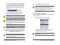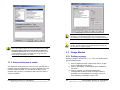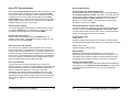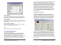
1
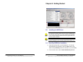
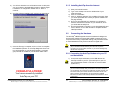
User’s Manual
USB AutoTap / Serial AutoTap
This product designed and manufactured in Ottawa, Illinois USA by
© 1998-2005 B&B Electronics Mfg. Co.
Documentation Number: AT-3105 Manual
B&B Electronics Mfg Co Inc – 707 Dayton Rd - PO Box 1040 - Ottawa IL 61350 - Ph 815-433-5100 - Fax 815-433-5104
3.1.2
TABLE OF CONTENTS
3.2
How this guide is organized.................................................1
Conventions used in this guide............................................1
REPAIR SERVICE...............................................................3
Chapter 1: Product Introduction .........................................4
1.1
Package Contents....................................................5
1.2
AutoTap, My Car and My PC ...................................5
Chapter 2: Getting Started ....................................................8
2.0
Installing the USB Drivers ........................................8
2.1.1
AutoTap USB Driver Installation ..........................8
2.1.2
Installing AutoTap software from the CD-ROM....9
2.1.3
Installing AutoTap from the Internet ...................12
2.2
Connecting the Hardware ......................................12
2.2.1
Connecting the AutoTap Hardware to your PC
and Automobile ..............................................................12
2.3
Software Registration (Serial and USB).................13
2.3.1
First time installation ..........................................13
2.3.2
Using AutoTap for Windows Software ...............14
2.4
Saving Your Configuration .................................16
2.4.2
Opening Your Configuration...............................17
3.2.2
Advanced features of a gauge ...........................23
Graph Window .......................................................24
3.3.1
Defining a graph.................................................24
3.3.2
Advanced features of a graph ............................24
DTC/Emissions Status Window .............................25
3.4.1
DTC Screen .......................................................25
3.4.1
Emission Test Screen ........................................29
3.5
AutoTap Status Bar................................................32
Chapter 4: Data Logging with AutoTap .............................33
4.1
How to log data ......................................................33
4.2
How to review a log file ..........................................34
4.2.1 Playing a log file with its associated config file. ....34
4.3
How to export logged data .....................................35
Chapter 5: Troubleshooting ...............................................37
5.1
Helpful Hints...........................................................37
®
AutoTap ATS Model Technical Specifications................40
AutoTap® ATU Model Technical Specifications................41
AutoTap Appendix.................................................................1
Anatomy of the Diagnostic Trouble Code ............................1
Saving/Opening Your Configuration ......................16
2.4.1
Defining a gauge ................................................22
3.4
Welcome!.............................................................................4
Gauge Window ......................................................22
3.2.1
3.3
WARRANTY INFORMATION ..............................................3
Advanced features of a table .............................21
Types of DTC's ....................................................................2
OBDII Acronyms and Jargon ...............................................3
Chapter 3: Setting Up AutoTap to Display Data ...............19
3.1
Parameter Table Window ......................................20
3.1.1
Defining a table ..................................................20
Documentation Number: AT-3105 Manual
B&B Electronics Mfg Co Inc – 707 Dayton Rd - PO Box 1040 - Ottawa IL 61350 - Ph 815-433-5100 - Fax 815-433-5104
i
ii
Documentation Number: AT-3105 Manual
B&B Electronics Mfg Co Inc – 707 Dayton Rd - PO Box 1040 - Ottawa IL 61350 - Ph 815-433-5100 - Fax 815-433-5104
WARNING:
About this guide
DO NOT attempt to operate or observe a computer
while driving!
Most readings can be obtained while stationary.
If data must be obtained while driving, have a passenger
operate and watch the computer, or use the AutoTap’s
logging option for later review.
This user manual contains complete information for the use of the
AutoTap® OBDII Diagnostic Scanner.
How this guide is organized
WARNING:
* Chapter 1: Product Introduction. An introduction to product
features and content.
* Chapter 2: Getting Started. A guide to installing the software and
making the connection.
* Chapter 3: Setting up AutoTap to Display Data. See the data
and various ways to view it with AutoTap.
* Chapter 4: Data Logging with AutoTap. Capturing and reviewing
your vehicle’s data for analysis.
* Chapter 5: Troubleshooting. Some answers to issues that you
may run into and how to solve them.
* Appendix: Explaining the codes and other industry jargon.
DO NOT turn your engine on indoors unless you have
proper ventilation.
A running engine produces carbon monoxide; an
odorless, colorless gas that can kill you.
WARNING:
Do not use a power inverter power supply to power
your laptop while using AutoTap.
This power supply will damage your AutoTap.
Conventions used in this guide
To make sure that you perform setup tasks properly, take note of the
following symbols used throughout this manual.
WARNING! Important information to prevent injury.
CAUTION! Information to prevent damage to components.
IMPORTANT! Information that is critical to success of task.
NOTE! Tips and other helpful information.
Documentation Number: AT-3105 Manual
B&B Electronics Mfg Co Inc – 707 Dayton Rd - PO Box 1040 - Ottawa IL 61350 - Ph 815-433-5100 - Fax 815-433-5104
1
2
Documentation Number: AT-3105 Manual
B&B Electronics Mfg Co Inc – 707 Dayton Rd - PO Box 1040 - Ottawa IL 61350 - Ph 815-433-5100 - Fax 815-433-5104
Chapter 1: Product Introduction
WARRANTY INFORMATION
All B&B Electronics products carry a five year limited warranty.
Product warranty or service will not be extended if the product is
modified or altered.
Returns: If, for any reason, you wish to return a hardware product
purchased direct from us, you may return it via UPS or insured
Parcel Post, undamaged, with the receipt, within 30 days of
purchase, for a full refund, less shipping charges. Call, fax, e-mail or
write to request a Return Material Authorization (RMA) number and
routing instructions.
Packages returned without prior authorization will be refused. All
products returned to B&B after 30 days may be charged a 20%
restocking fee. Duties, taxes and customs charges are the buyer’s
responsibility.
Welcome!
Thank you for buying AutoTap® OBDII Diagnostic
Scanner!
Products purchased from resellers must be returned through the
reseller.
The AutoTap® OBDII Diagnostic Scanner, coupled with a personal
computer, allows you to access your OBDII vehicle’s computer
modules. Vehicle data, which was once only available to dealership
technicians using expensive factory scan tools, is now only a few
mouse clicks away at your PC! AutoTap® is the prime choice for
users ranging from the do it yourself beginner, to the professional
service personnel.
REPAIR SERVICE
We offer a repair service for products that are out of warranty.
Please call, fax, e-mail or write to request a Return Material
Authorization (RMA) number. Duties, taxes and customs charges
are the buyer’s responsibility.
~ Read Diagnostic Trouble Codes (DTCs)
B&B Electronic Mfg. Co. - Contact Information
Address:
707 Dayton Road
PO Box 1040
Ottawa, IL 61350
~ Reset “Check Engine” light trouble codes
~ Check if your vehicle is ready for Emissions Certification
~ View real-time vehicle operation data
Telephone:
Fax:
(815) 433-5100
(815) 433-5105
Website:
www.autotap.com (AutoTap)
www.bb-elec.com (B&B Electronics)
www.obdii.com (OBDII Information)
Email:
~ View data in list, graph, or gauge modes
~ Record real-time vehicle operation data for future analysis
The AutoTap® OBDII Diagnostic Scanner is the perfect scan tool
whether you are simply diagnosing a problem, or analyzing and
tuning your vehicle for maximum performance!
[email protected] (Support)
[email protected] (Sales)
[email protected] (Resellers)
Documentation Number: AT-3105 Manual
B&B Electronics Mfg Co Inc – 707 Dayton Rd - PO Box 1040 - Ottawa IL 61350 - Ph 815-433-5100 - Fax 815-433-5104
3
4
Documentation Number: AT-3105 Manual
B&B Electronics Mfg Co Inc – 707 Dayton Rd - PO Box 1040 - Ottawa IL 61350 - Ph 815-433-5100 - Fax 815-433-5104
1.1
CAUTION: There are some 1994 and 1995 vehicles with this
connector. Although the connector is the same as OBDII, most of
these vehicles will have an OBD I compliance sticker under the
hood and will NOT work with the AutoTap scanner. However, there
are a few pre-’96 vehicles that will work with AutoTap. A list of these
vehicles is available at www.obdii.com/connector.html.
Package Contents
Check your AutoTap® package for the following items.
AutoTap Hardware Converter Module
AutoTap CD (includes this manual)
Software Registration Certificate
Quick Start Guide
Serial
Version
√
√
√
√
USB
Version
√
√
√
√
Will my laptop or desktop PC work with AutoTap?
Typically, a PC that has a serial port and runs Windows 95 (or
newer) will be enough to run the serial version of AutoTap. The
USB version requires your PC to have a USB port and run Windows
98 or newer.
NOTE: If any of the above items are damaged or missing, please
contact B&B Electronics immediately.
1.2
AutoTap, My Car and My PC
The AutoTap® OBDII Diagnostic Scanner is designed to operate on
USA-spec OBDII-equipped cars. This includes model year 1996 and
newer cars, light trucks and SUV’s. The software bundled with the
AutoTap hardware is designed to run on any desktop or laptop PC
equipped with one serial port or USB and running Windows 98 or
newer. Let us begin with a few basics to become familiar with the
hardware/software compatibility between your car and PC.
Here is a list of minimum PC hardware requirements:
√
√
√
√
√
√
√
How do I find out if my vehicle meets OBDII specifications?
Begin by looking under the hood for a sticker stating that the vehicle
meets OBDII compliance specifications.
Pentium 233Mhz or better (or equivalent AMD processor)
Windows 95, 98, NT, ME, 2000 or XP
50 MB of free hard drive space
32 MB RAM (64+ MB recommended)
CD-Rom Drive (Only used for installation)
9-pin male RS-232 (Serial) Port for serial model numbers
USB port of USB model numbers
*NOTE: Windows 95 and Windows NT do not support USB.
NOTE: All USA-spec vehicles manufactured in 1996 and
later are OBDII compliant. However, 1997 and newer
vehicles may not have the OBDII sticker under the hood.
OBDII vehicles have a 16-pin connector under the dash or in
another location near the driver’s seat. Sometimes, there is a plastic
cover that is slightly larger than the AutoTap connector concealing
the vehicle’s OBDII port. This cover is usually labeled “OBDII.”
Remove this cover if your vehicle is equipped with it.
The 16-pin OBDII port pictured below is the connector that you will
see and be attaching to the AutoTap Scanner shortly.
Documentation Number: AT-3105 Manual
B&B Electronics Mfg Co Inc – 707 Dayton Rd - PO Box 1040 - Ottawa IL 61350 - Ph 815-433-5100 - Fax 815-433-5104
5
6
Documentation Number: AT-3105 Manual
B&B Electronics Mfg Co Inc – 707 Dayton Rd - PO Box 1040 - Ottawa IL 61350 - Ph 815-433-5100 - Fax 815-433-5104
Chapter 2: Getting Started
2.0
Installing the USB Drivers
IMPORTANT: It is important that you understand the basic operation
of the Windows operating system and have a basic understanding of
your personal computer (PC). If you have questions about Windows
or your computer hardware, please have the user guides that came
with the computer available.
NOTE: If you have the serial version of AutoTap (with a 9-pin
connector that plugs into your computer, please skip to section 2.1.2
2.1.1 AutoTap USB Driver Installation
1) Insert the AutoTap CD in your CD ROM drive. The CD will
automatically load. If It doesn’t, click the “Start” button, click
“Run” and type D:Setup (where D is the letter of your CD ROM.)
2) From the main menu, select “Install USB AutoTap drivers”
Documentation Number: AT-3105 Manual
B&B Electronics Mfg Co Inc – 707 Dayton Rd - PO Box 1040 - Ottawa IL 61350 - Ph 815-433-5100 - Fax 815-433-5104
7
8
Documentation Number: AT-3105 Manual
B&B Electronics Mfg Co Inc – 707 Dayton Rd - PO Box 1040 - Ottawa IL 61350 - Ph 815-433-5100 - Fax 815-433-5104
3) Connect the USB version of AutoTap to your computer when
prompted. Follow the on screen instructions to install two
sets of drivers needed by AutoTap.
3) Click on the “Next” button to begin installation of the
software. This will bring you to the Destination Folder screen
as seen below. The software will then prompt you to specify
the directory in which the software will be installed. The
default directory is listed and it is recommended that the
default directory be used for most installations. If you need
to change the installation location, then you will need to click
on “Browse” at this time and make the necessary directory
changes.
4) When the driver installations are complete, skip to section
2.1.2 below to install your software.
NOTE: If you need to uninstall the USB drivers, ensure that AutoTap
is unplugged from your computer, then click Start > Settings > Control
Panel > Add or Remove Programs, select USB AutoTap Drivers and
follow the on screen instructions.
2.1.2
Installing AutoTap software from the CD-ROM
NOTE: The AutoTap software may be installed on your PC/laptop at
any time. The computer does not have to be attached to either the
AutoTap cable or the car for AutoTap software installation.
1) Insert the AutoTap CD in your CD ROM drive. The CD will
automatically load. If It doesn’t, click the “Start” button, click
“Run” and type D:Setup (where D is the letter of your CDROM.)
4) After you have selected your destination folder for the
software installation, click on “Next.”
2) From the main menu, select “Install Software” and then
choose AutoTap for Windows. When the installation begins,
you’ll see:
Documentation Number: AT-3105 Manual
B&B Electronics Mfg Co Inc – 707 Dayton Rd - PO Box 1040 - Ottawa IL 61350 - Ph 815-433-5100 - Fax 815-433-5104
9
10
Documentation Number: AT-3105 Manual
B&B Electronics Mfg Co Inc – 707 Dayton Rd - PO Box 1040 - Ottawa IL 61350 - Ph 815-433-5100 - Fax 815-433-5104
5) You will now be taken to a confirmation screen. At this point
you can go back to the destination screen to make changes
if needed. If no changes are needed click on “Next” to
continue.
2.1.3 Installing AutoTap from the Internet
1) Start your internet browser.
2) Type: www.autotap.com into the Address bar of your
Internet browser.
3) Click on “Downloads.”
4) Click on “Windows software” in the middle of the page. Here
you will be presented with a variety of options. Please read
the page carefully.
5) Once you have selected your download, you will want to
save the download to a location on your hard drive, which
you will be able to easily find.
6) Once the download is complete, run the downloaded file and
refer to Section 2.1.2 of this manual for complete software
install procedures.
6) AutoTap software installation will now begin as seen below.
2.2
Connecting the Hardware
The AutoTap® OBDII Diagnostic Scanner Hardware is designed to
provide a link between the automobile’s OBDII computer and your
computer without using complicated cabling, bulky translation boxes
or other hardware that may be inconvenient for regular use.
CAUTION: AutoTap Hardware as well as your personal computer
(PC) is sensitive to static electricity. Do not touch any of the
connector pins on the cables, module, or your PC as damage may
result to the component.
7) Once the file copy is complete, click on “Close” to complete
the installation process. An “AutoTap Diagnostic Scan Tool”
icon will be placed on your Windows Desktop. A program
group will also be created in your Windows “Start” menu.
2.2.1 Connecting the AutoTap Hardware to your PC
and Automobile
1) Connect the 9-pin serial cable, or the USB cable of the
AutoTap module to your PC. (The serial port on your PC
may be marked as “COM” or “RS-232” or have a modem
symbol on it.)
IMPORTANT: Some personal computers do not have a serial port. If
you own a serial AutoTap and your PC does not have a serial port,
you will need to use a serial port to USB port converter module. You
will need to order part number UC232A for Windows 98, Me, and
2000 computers, and Edgeport/1 for XP machines from B&B
Electronics in order for the AutoTap hardware and software to work
as designed.
CONGRATULATIONS!
You have successfully installed
AutoTap on your PC!
Documentation Number: AT-3105 Manual
B&B Electronics Mfg Co Inc – 707 Dayton Rd - PO Box 1040 - Ottawa IL 61350 - Ph 815-433-5100 - Fax 815-433-5104
11
12
Documentation Number: AT-3105 Manual
B&B Electronics Mfg Co Inc – 707 Dayton Rd - PO Box 1040 - Ottawa IL 61350 - Ph 815-433-5100 - Fax 815-433-5104
2) With the key turned to the ON position (engine does not
have to be running), plug the OBDII cable end of the module
into the automobile’s 16-pin OBDII connector (refer to
Section 1.2 of this manual to identify the connector).
You are now ready to register your AutoTap software.
2.3
Software Registration (Serial and USB)
IMPORTANT: Please locate the Software Registration Certificate
supplied by B&B Electronics with the A utoTap product. If you
cannot find this item, please contact B&B Electronics customer
service.
2.3.1 First time installation
1) Make sure your computer is booted to Windows and that all
your programs are closed. (If your computer is not on, turn
on and let it boot up.)
2) Ensure that the AutoTap hardware is connected to your
vehicle as described in the previous section and that your
vehicle’s key is in the “On” position.
3) Double click on the “AutoTap Diagnostic Scan Tool” icon on
your Windows desktop screen.
5) Enter the product registration number and click on
“Register”. Your AutoTap is now registered. Save your
registration information in case you need to re-install the
software on this or another computer.
2.3.2 Using AutoTap for Windows Software
1) After you have successfully registered your software,
AutoTap will attempt to retrieve your vehicle’s VIN. If your
vehicle supports automatic VIN retrieval, skip to #4 below
2) If AutoTap does not retrieve your vehicle’s VIN, you will be
prompted to enter it. It is important that you enter all 17
characters of the VIN, or AutoTap will not work properly.
Click “Connect with VIN”.
3) If you elect not to enter your VIN, you can select “Connect
without VIN”. AutoTap will connect to your vehicle and
display OBDII generic parameters.
4) The AutoTap software will search for the AutoTap hardware
module and check for a valid software registration number.
Since this is the first time you are running the software
connected to the hardware, you will be prompted to enter
the registration number before continuing.
Documentation Number: AT-3105 Manual
B&B Electronics Mfg Co Inc – 707 Dayton Rd - PO Box 1040 - Ottawa IL 61350 - Ph 815-433-5100 - Fax 815-433-5104
13
IMPORTANT: If you are registered for manufacturer’s enhanced
parameters, you must enter your VIN. Connecting without the VIN
will only allow viewing of OBDII generic parameters.
14
Documentation Number: AT-3105 Manual
B&B Electronics Mfg Co Inc – 707 Dayton Rd - PO Box 1040 - Ottawa IL 61350 - Ph 815-433-5100 - Fax 815-433-5104
4) Once AutoTap has retrieved your VIN, or you have entered
it, AutoTap will check for Diagnostic Trouble Codes (DTC),
which may be stored in the onboard control module. The
software will then retrieve a list of all scan tool parameters
supported by the vehicle. Note that this may take a few
minutes, depending on your vehicle and the speed of your
computer.
5) Once the parameter detection process is complete, the
screen will show all of your vehicle’s generic OBDII
parameters and any diagnostic trouble codes.
2.4
Saving/Opening Your Configuration
NOTE: It is recommended that you save your configuration
whenever you connect to a new vehicle for the first time or make a
change to one of the configured windows in your current
configuration. This will save you time in future sessions with the
same vehicle, and will allow you to make configuration changes
without being connected to the vehicle.
2.4.1 Saving Your Configuration
NOTE: By default, the AutoTap software will check for DTCs each
time the software starts. If you would like to disable this feature, click
on “Options” from the toolbar and deselect “Read DTCs at startup”.
Saving your configuration is as simple as 1 – 2 – 3! You can save
your vehicle configuration/information file at any time once AutoTap
is running. Here is how:
1) Click on File at the top of the AutoTap screen.
2) Click on “Save Config File” in the drop down menu.
NOTE: It is recommended that at this time you go to the File menu
and select “Save Config As” in order to save the configuration file for
the particular vehicle you are connected to. This way, you can
bypass the parameter scan process the next time you connect to the
vehicle. Save the file with a name that will easily identify the vehicle,
i.e. 98 Chevy Malibu.
NOTE: The first time a vehicle is connected, AutoTap must
complete a full parameter scan.
You are now connected and running the AutoTap
software. You may continue on to configuring the
AutoTap screen with data.
3) You will be prompted with a standard Windows “Save As”
window. Type in the name you wish to use for the
configuration file and click on “SAVE.”
NOTE: If you select “Save Config File”, you will overwrite the
existing config file.
NOTE: AutoTap automatically loads the last-used config file if the
VIN matches the connected vehicle. If the VINs don’t match, you will
be prompted to open a previously saved config, or scan the current
vehicle for supported parameters.
Documentation Number: AT-3105 Manual
B&B Electronics Mfg Co Inc – 707 Dayton Rd - PO Box 1040 - Ottawa IL 61350 - Ph 815-433-5100 - Fax 815-433-5104
15
16
Documentation Number: AT-3105 Manual
B&B Electronics Mfg Co Inc – 707 Dayton Rd - PO Box 1040 - Ottawa IL 61350 - Ph 815-433-5100 - Fax 815-433-5104
2.4.2 Opening Your Configuration
Opening your configuration file is also as simple as 1 – 2 – 3! You
can open your configuration file while connected to the vehicle or
simply working at your desk setting up configuration screens. Here is
how:
1) Click on File at the top of the AutoTap screen.
2) Click on “Open Config File…” in the drop down menu.
3) You will be prompted with a standard Windows “Open”
window. Click on the name of the configuration file you wish
to open and then click on “Open.”
NOTE: There are buttons in the toolbar that contain the Save
Configuration and Open Configuration functions. These are there to
provide you with a quick means of performing these tasks. Move the
mouse over the buttons to become familiar with what they are and
they will save you time using drop down menus.
Documentation Number: AT-3105 Manual
B&B Electronics Mfg Co Inc – 707 Dayton Rd - PO Box 1040 - Ottawa IL 61350 - Ph 815-433-5100 - Fax 815-433-5104
17
18
Documentation Number: AT-3105 Manual
B&B Electronics Mfg Co Inc – 707 Dayton Rd - PO Box 1040 - Ottawa IL 61350 - Ph 815-433-5100 - Fax 815-433-5104
3.1
Chapter 3: Setting Up AutoTap to Display Data
Parameter Table Window
The AutoTap® OBDII Diagnostic Scanner software can display
diagnostic information in a variety of formats. This includes data
tables, graphs and gauges. You can use the different display
methods to fit your logging or viewing needs. For example, if you are
logging data for future review, a data table display may be preferred.
Or you can use the gauges to create a “virtual” dashboard. The
flexibility of these formats allows for hundreds of combinations
supplying you with maximum flexibility not only in diagnostics, but
also in vehicle data acquisition for performance tuning.
IMPORTANT: It is natural to want to see all data available.
However, the more data you view, the slower each parameter’s
value is refreshed. This is very important to remember as we cover
viewing data, and especially logging. We recommend you display
only the data related to the issue you’re working on. This will
maximize the update rate.
3.1.1 Defining a table
Defining a Table is as simple as 1 – 2 – 3! You can setup a few
parameters in a Table and view data in no time. Here’s how.
NOTE: To Create a Custom Configuration you will need to clear the
current Display. Click on “File” on the top of the AutoTap Screen.
This will display a drop down menu. Click on “Clear Page.” You are
now ready to create your custom configuration!!
Documentation Number: AT-3105 Manual
B&B Electronics Mfg Co Inc – 707 Dayton Rd - PO Box 1040 - Ottawa IL 61350 - Ph 815-433-5100 - Fax 815-433-5104
19
1) Click on “Display” at the top of the AutoTap screen, or right
click anywhere on the screen.
2) Click on “Add Table”. A blank table will be displayed on the
screen.
3) Click “Add.” You will be presented with a “Category/Item”
window in which you simply check the parameter(s) you
want displayed in your table. Once you have selected your
parameters, simply click on “OK.” This will insert your
selected parameters into your table.
20
Documentation Number: AT-3105 Manual
B&B Electronics Mfg Co Inc – 707 Dayton Rd - PO Box 1040 - Ottawa IL 61350 - Ph 815-433-5100 - Fax 815-433-5104
NOTE: For instant graphs and gauges, point your mouse at a
parameter in your table and right-click on it. This will bring up a
menu allowing you to instantly graph or setup a gauge for that item.
NOTE: If you want to select all of the available parameters, simply
click on the “Select all items” box in the lower left-hand corner. We
recommend that you save one config file with all parameters
selected for each vehicle. Once you have this file saved, you can
configure additional screens and make other configuration files
without being connected to your vehicle.
NOTE: Do not place the same parameter in more than one display
at a time. In other words, if you have Engine Speed in a table, do
not also place it in a graph or gauge.
3.2
Gauge Window
3.2.1 Defining a gauge
Defining a Gauge is as simple as 1 – 2 – 3! You can quickly setup a
gauge and display data.
3.1.2 Advanced features of a table
1) Click on Display at the top of the AutoTap screen, or right
click on a blank area of the screen.
2) Click on “Add Gauge”. A blank gauge will be displayed on
the screen.
3) Click on “Change.” You will be presented with a
“Category/Item” window in which you simply check the
parameter you want displayed in your gauge. Once you
have selected your parameter, click on “OK.”
The “advanced” button gives you control over the “look and feel” of
the table. From the “advanced” tab, you can change the color, size,
and fonts used in the table. You can also set up alerts to have
AutoTap notify you when a parameter’s data is above or below a
value you supplied.
Documentation Number: AT-3105 Manual
B&B Electronics Mfg Co Inc – 707 Dayton Rd - PO Box 1040 - Ottawa IL 61350 - Ph 815-433-5100 - Fax 815-433-5104
21
22
Documentation Number: AT-3105 Manual
B&B Electronics Mfg Co Inc – 707 Dayton Rd - PO Box 1040 - Ottawa IL 61350 - Ph 815-433-5100 - Fax 815-433-5104
3.3
Here is a picture of what your gauge may look like:
Graph Window
3.3.1 Defining a graph
You guessed it - defining a Graph is also as simple as 1 – 2 – 3!
1) Click on Display at the top of the AutoTap screen, or right
click anywhere on the screen.
2) Click on “Add Graph”. A blank graph will be displayed on the
screen.
3) Click “Insert.” You will be presented with a “Category/Item”
window in which you simply check the parameter(s) you
want displayed in your graph. Once you have selected your
parameter(s), click on “OK.”
3.2.2 Advanced features of a gauge
The “advanced” button gives you control over the “look and feel” of
the gauge. From the “advanced” tab, you can change the gauge
style, color, size, and fonts used in the gauge. You can also set up
alerts to have AutoTap notify you when a parameter’s data is above
or below a value you supplied. (The Gauge Range will need to be
modified to fit the assigned parameter.)
Here is a picture of what your graph may look like:
3.3.2 Advanced features of a graph
The “advanced” button gives you control over the “look and feel” of
the graph. From the “advanced” tab, you can change the color, size,
and fonts used in the graph. You can also set up alerts to have
AutoTap notify you when a parameter’s data is above or below a
value you supplied.
Documentation Number: AT-3105 Manual
B&B Electronics Mfg Co Inc – 707 Dayton Rd - PO Box 1040 - Ottawa IL 61350 - Ph 815-433-5100 - Fax 815-433-5104
23
24
Documentation Number: AT-3105 Manual
B&B Electronics Mfg Co Inc – 707 Dayton Rd - PO Box 1040 - Ottawa IL 61350 - Ph 815-433-5100 - Fax 815-433-5104
The following sections explain each element of the DTC Screen
display and how it is used.
3.4
Check Engine Light Indicator
The Check Engine Light, also known as Malfunction Indicator Light
(MIL), will appear on the vehicle dashboard if any of the Emission
Monitors have detected a reoccurring problem in the engine. (Some
manufacturers may go above and beyond the spec, and turn on the
light for other reasons) The lamp will usually remain on unless the
fault does not occur again for three consecutive drive cycles. If the
ODB II sees no further evidence of the problem, it will turn off the
light and erase the code.
DTC/Emissions Status Window
3.4.1 DTC Screen
When the AutoTap Software has successfully connected to the vehicle
and read the DTC codes and the DTC Window will be displayed. DTC
stands for Diagnostic Trouble Codes. These are codes logged by the
engine controller signifying problems in some area.
When there’s a problem with your car and your check engine light is
on, the first thing you’ll want to do is read the trouble codes. AutoTap
makes it easy! AutoTap automatically checks for DTCs when you
connect to your vehicle and start the software. AutoTap displays any
trouble codes stored in the vehicle’s computer as well as any
pending DTCs that have not yet caused the MIL to illuminate.
If the Check Engine Light Indicator is turned on within the
automobile dashboard, it will show as RED with the words CHECK
in the Check Engine Indicator. The button to the right will read
CLEAR. If the dashboard light is not illuminated, it will show as
GREEN with the words OK in the Check Engine Indicator. The
button to the right will be inactive if there are no DTCs detected.
The user may choose to turn off the Check Engine Light Indicator
within the dashboard by clicking the CLEAR button. The CLEAR
button will send a message to the Vehicle on board computer to clear
all DTC error codes and turn off the Engine Light. However, if there is
really an engine problem, the error codes will reappear after a few
Drive Cycles. See next section for more information on Drive Cycles.
IMPORTANT: Clearing the engine light will ALSO clear the
Emission Status Monitors on the following screen. It will be
important to drive the car several times for one complete
drive cycle (per the definition below) for these to be reset
before an actual Emission test will pass.
Documentation Number: AT-3105 Manual
B&B Electronics Mfg Co Inc – 707 Dayton Rd - PO Box 1040 - Ottawa IL 61350 - Ph 815-433-5100 - Fax 815-433-5104
25
26
Documentation Number: AT-3105 Manual
B&B Electronics Mfg Co Inc – 707 Dayton Rd - PO Box 1040 - Ottawa IL 61350 - Ph 815-433-5100 - Fax 815-433-5104
Since DTC Cleared Indicator
DTCs and Descriptions
The box labeled Since DTC Cleared is provides information on how
long it has been since the last time someone clicked the CLEAR
button to turn off the Check Engine Light and clear the DTCs. This
is helpful since reoccurring errors will eventually turn the Check
Engine Light back on. If the vehicle has been driven for significant
time and distance and the DTC errors have not returned, this is an
indicator that the error may no longer exist.
Possible Diagnostic Trouble Codes (DTC)
If the Onboard Computer has detected a fault, it will be displayed in
the Possible Diagnostic Trouble Code Table. If the fault continues
for more than 3 Drive Cycles, the trouble code will be moved to the
Confirmed Diagnostic Trouble Code Table. The first column
shows the error code number. The second column shows a text
description of the error if available.
Time Since DTC Cleared
The AutoTap application starts a timer once the DTCs are cleared
by using the CLEAR button. It will display how many hours and
minutes the car has been driven since the last CLEAR.
Confirmed Diagnostic Trouble Codes (DTC)
If the fault continues for more than 3 Drive Cycles, the trouble code
will be moved to the Confirmed Diagnostic Trouble Code Table.
The first column shows the error code number. The second column
shows a text description of the error if available.
Distance since DTC Cleared
Once the DTCs are cleared by using the CLEAR button, the
distance counter starts. It will display how many miles the car has
been driven since the last CLEAR.
Common DTC Codes
P0300 Misfire
Possible Causes: Lean fuel due to vacuum leak in intake manifold,
unmetered air getting past airflow sensor, or an EGR valve stuck open.
Drive Cycle since DTC Cleared
Once the DTCs are cleared by using the Clear button, the Drive
Cycle counter starts. It will display how many Drive Cycles the car
has been driven since the last CLEAR. If a problem is persistent in
the vehicle engine, the DTC codes will register again after several
Drive Cycles. (The number of cycles required vary by manufacturer,
but is most commonly 3 full Drive Cycles) Emission Monitors also
require one full Drive Cycle to set after the CLEAR.
P0440 Vapor Leak
Possible Causes: Loose gas cap
Drive Cycle Definition
A Drive Cycle is not just turning the ignition key on and off, or
starting the engine. A drive cycle requires starting a cold engine and
driving until the engine reaches normal operating temperature (at
least an increase of temperature of 22 C (40 F) from start
temperature and reaches a minimum temperature of 70 C (160 F).
The engine must then be shut off and allowed to cool completely
before a second cycle will be counted. Some vehicle manufactures
even require an eight-hour cooling period before the next cycle is
counted.
Display Freeze Frame Button
The vehicle’s computer stores freeze frame data at the time the DTC
is set. When you Click Display Freeze Frame Button, you’ll see the
conditions that were present at the time your check engine light
illuminated.
Documentation Number: AT-3105 Manual
28
B&B Electronics Mfg Co Inc – 707 Dayton Rd - PO Box 1040 - Ottawa IL 61350 - Ph 815-433-5100 - Fax 815-433-5104
27
Refresh Button
Refresh will cause the AutoTap application to reconnect to the
Vehicle and read the DTC and Emission Monitor codes again. The
new values will be displayed. Make sure that the OBD II connector
is plugged into the PC and the vehicle, and the key is turned ON.
Documentation Number: AT-3105 Manual
B&B Electronics Mfg Co Inc – 707 Dayton Rd - PO Box 1040 - Ottawa IL 61350 - Ph 815-433-5100 - Fax 815-433-5104
There are 11 monitors that are relevant to the emissions test. These
monitors are set anytime a vehicle has a fault that may cause
emissions to exceed the federal limits. It does not necessarily mean
that the vehicle has a real emission problem. In some states, the
motorists may be allowed to opt for a tailpipe test if their vehicle fails
an OBD II test. Not all vehicles have all 11 monitors. If the monitor
does not exist, it will show as NOT AVAILABLE. If a situation
develops in any of the monitored systems that could cause an
emissions problem, the OBD II will watch the situation, and set a
code. If the situation continues, the CHECK ENGINE LIGHT will be
lit. If the CHECK ENGINE LIGHT is ON, the car will not pass
emissions testing.
AutoTap Emission Test Screen
Save Data Button
Save Codes will create a text file of all current DTC and Emission
Monitor Status. It will prompt you for a file name and location. This
file can be open and read by any NotePad or text based editor.
The Emission Status Screen shows the results of the Emission
Test Data. These results are based upon Industry Standard
Guidelines for emission controls. It should be noted, however, that
the Standards are simply guidelines. Each individual state has its
own testing criteria. Therefore, PASS or FAIL status does NOT
guarantee that the same test results will occur in your state.
Open Data Button
Open Codes will open the text file with any saved DTC and Emission
Monitor Status. The application will display a NotePad window for
viewing the file.
Emission Test Screen Button
The Emission Test Screen button will switch views to the Emission
Screen for viewing Emission Monitor status.
Exit
Clicking the Exit button will close the AutoTap program.
3.4.1 Emission Test Screen
About Emission Test Methods.
There are two methods that states use for Emission Certification
tests. The older method uses the tailpipe test, which measures
direct vehicle emissions. The newer method uses Onboard
Diagnostic II (ODBII) tests. The ODBII method checks the Onboard
computer monitors for the internal measurements of vehicle
emissions data. The OBD II Tests will use a J1962 diagnostic tool
similar to AutoTap.
Documentation Number: AT-3105 Manual
B&B Electronics Mfg Co Inc – 707 Dayton Rd - PO Box 1040 - Ottawa IL 61350 - Ph 815-433-5100 - Fax 815-433-5104
29
When this screen is initially displayed, the Vehicle Model Year must
be set. These results of the test will depend upon the year the
vehicle was manufactured. Older cars are given more leeway to fail
in one or two monitor areas and yet still pass the Emission Status
Testing. Newer cars are not allowed to have any monitor failures.
The PASS/FAIL criterion depends upon the state where the test is
performed. Once the Vehicle Model Year is selected, the test status
will be displayed.
30
Documentation Number: AT-3105 Manual
B&B Electronics Mfg Co Inc – 707 Dayton Rd - PO Box 1040 - Ottawa IL 61350 - Ph 815-433-5100 - Fax 815-433-5104
COMPLETE
Vehicle Model Year
The year the vehicle was manufactured. The Autotap program does not
support any model years prior to 1996.
NOT COMPLETE
Emission Status
There are 11 monitors that may signify emissions problems. To set the
monitors correctly, the vehicle must be driven a certain distance at a
variety of different speeds. The exact requirement depends upon the
make and model of the vehicle. As a general rule, doing some stop-andgo driving around town plus 5-10 minutes on the highway will usually set
all monitors. Please see Drive Cycle definition for more information.
Emission Status will display one of three possible results:
NOT READY – If Emission Status displays NOT READY this means that
the engine has not completed all of its’ self-tests. In order for the engine
to run the self tests a drive cycle must be completed. See the
description of a drive cycle in this manual for more information.
PASS – The Emission Status test is able to be run and has passed.
FAIL – The Emission Status test is able to be run and has failed. The
test will fail if the Check Engine Light is on and Confirmed Diagnostic
Trouble Codes (DTCs) are present.
MIL
MIL or Malfunction Indicator Light is another name for the Check Engine
Light. It will appear on the vehicle dashboard if any of the Emission
Monitors have detected a reoccurring problem in the engine. The lamp
will usually remain on unless the fault does not occur again for three
consecutive drive cycles. If the ODB II sees no further evidence of the
problem, it will turn off the light and erase the code.
The MIL status field will show the status of the Check Engine Light in the
vehicle. It will read either ON or OFF. The vehicle will not pass the
Emissions Test if the Check Engine Light is ON.
NOT SUPPORTED
The Engine Monitor status reads correctly
and is working within guidelines
The Engine Monitor is NOT reading
correctly. If too many monitors read this
way, the Emission Status Test will NOT
Pass. A Monitor can read NOT
COMPLETE because there is an emissionbased problem OR because the Check
Engine Light was recently CLEARED.
The Engine Control Unit does not support
this particular monitor. It will not count as a
failed test during Emissions Testing.
Refresh Button
Refresh Button will cause the AutoTap application to reconnect to
the Vehicle and read the DTC and Emission Monitor codes again.
The new values will be displayed. Make sure that the OBD II
connector is plugged into the PC and the vehicle, and the key is
turned ON.
DTC Code Screen Button
The DTC Code Screen button will switch views to show the DTC
Code Screen.
3.5
AutoTap Status Bar
At the bottom of the main AutoTap window, you will see a status bar
that gives you information about the config and log files you’re using,
as well as, whether you’re connected to the vehicle, and whether
your MIL is on. If you’re playing back a log file, the status bar keeps
track of what record of the log file is being displayed.
Config file
name
Log file
name
Connected
to vehicle?
Log file
playback record
Currently
logging?
Emission Monitor Status
There are 11 Monitors recorded by the Vehicle On Board Computer. It is
the result of these Monitor Tests that will determine if the Emission
Status will pass. The Monitors will have three possible Status Values.
The Number of NOT COMPLETE Emission Monitor values shows on the
DTC Screen. The values of the Emission Monitors show on the
Emission Status Screen.
Documentation Number: AT-3105 Manual
B&B Electronics Mfg Co Inc – 707 Dayton Rd - PO Box 1040 - Ottawa IL 61350 - Ph 815-433-5100 - Fax 815-433-5104
31
32
Documentation Number: AT-3105 Manual
B&B Electronics Mfg Co Inc – 707 Dayton Rd - PO Box 1040 - Ottawa IL 61350 - Ph 815-433-5100 - Fax 815-433-5104
MIL
status
3) When you want to stop logging, simply depress the
“Spacebar” one more time and it will stop. The screen will
return to normal color when logging is completed.
Chapter 4: Data Logging with AutoTap
4.2
How to review a log file
You can review the data that you have logged in multiple ways. You
can review it using the screens used to originally record the data, or
you have the option to export it as discussed below in Section 4.3.
IMPORTANT: It is important that you have a configuration of
your vehicle saved so that when you load a log file, you will
be able to define the tables, graphs or gauges. If you do not
have a saved configuration of your vehicle, connect to the
vehicle and save a configuration file for it.
4.2.1 Playing a log file with its associated config
file.
4.1
Not connected to vehicle:
1) Start the AutoTap software and select “Open a Log file for
Playback” from the main screen.
2) Next, click on “File” and select “Open Config File”. From the
Open dialog box, select the config file you used when you
recorded the log file. The screen will now look identical to
when you recorded the log file.
3) Now, click on “Playback” at the top of the screen.
4) Click on “Play” to begin. You will notice that the file is now
being replayed.
Connected to vehicle:
1) Click “Playback” on the toolbar and then select “Open File.”
2) Select the file that you wish to playback.
3) Now, click on “Playback” at the top of the screen.
4) Click on “Play” to begin. You will notice that the file is now
being replayed.
How to log data
®
The AutoTap OBDII Diagnostic Scanner not only displays real-time
data, it also allows you to record and save data to be viewed at a
later time. These log files can be exceptionally powerful tools for
diagnosing intermittent problems and for performance monitoring.
IMPORTANT: It is natural to want to log all data available.
However, the more data you log, the slower the response
rate from the vehicle computer. Display only the parameters
needed in order to maximize the vehicle computer’s update
rate. Only the parameters visible on the screen are logged.
NOTE! If you would like to change the configuration of the
screen for playback, add tables, graphs and/or gauges as
described in section 3. When you click “Insert” to add
parameters, the recorded parameters will be listed first,
followed by the remainder of the parameters which are
preceded by a “~”. These parameters were not recorded and
are not available for playback.
One of the most powerful features of AutoTap is its simplicity in
logging the vehicle’s sensor data. Here is how:
1) When you are ready to log, simply depress the “Spacebar”
on the keyboard! AutoTap will prompt you to name your log
file.
2) Type in a name for your log file and click on “save”. The
background of the AutoTap screen will change to red
indicating that logging is in progress.
Documentation Number: AT-3105 Manual
B&B Electronics Mfg Co Inc – 707 Dayton Rd - PO Box 1040 - Ottawa IL 61350 - Ph 815-433-5100 - Fax 815-433-5104
33
34
Documentation Number: AT-3105 Manual
B&B Electronics Mfg Co Inc – 707 Dayton Rd - PO Box 1040 - Ottawa IL 61350 - Ph 815-433-5100 - Fax 815-433-5104
Make note of the VCR-like buttons on the toolbar at the top of the
screen. These buttons will allow you to play, pause, stop, rewind,
fast-forward, etc. Become familiar with these, and viewing your log
files will be simple.
4.3
How to export logged data
AutoTap has the ability to export the data in your log file to a
“Comma Delimited” (.csv) file. This format is easily opened with most
popular database and spreadsheet software. This gives you the
ability to perform in depth analysis of the data collected by AutoTap.
Here is how to export data once you have logged it with AutoTap:
1) Once you have your log file loaded into AutoTap, click on
Logging at the top of the AutoTap screen.
2) Click on “Export to Comma Delimited File.” At this point, a
“Save As” window will open prompting you for a file name.
3) Type in a filename and click “Save.” When the process is
complete, the progress bar window will disappear.
Now you are ready to open the “.csv” file in your favorite database or
spreadsheet application and begin your analysis of the data
collected.
Documentation Number: AT-3105 Manual
B&B Electronics Mfg Co Inc – 707 Dayton Rd - PO Box 1040 - Ottawa IL 61350 - Ph 815-433-5100 - Fax 815-433-5104
35
36
Documentation Number: AT-3105 Manual
B&B Electronics Mfg Co Inc – 707 Dayton Rd - PO Box 1040 - Ottawa IL 61350 - Ph 815-433-5100 - Fax 815-433-5104
Chapter 5: Troubleshooting
Ensure that all of the cable connections are good and the key is in
the “On” position. Then select “Connect to Vehicle”.
5.1
Helpful Hints
No AutoTap found
Lost communications with the vehicle
If AutoTap loses communications with the vehicle it will display the
following message:
In the event that the window pictured below appears, the AutoTap
software cannot communicate with the AutoTap hardware. The problem
is most likely due to a faulty connection. Check the serial port connection
to both the computer and the AutoTap. Also check the connection
between AutoTap and the vehicle. If you are still getting this error after
you checked the connection, check and make sure that your computer
has the appropriate serial port defined in its hardware configuration.
If a “Retry” fails, refer to Chapter 2 of this guide to make sure a
critical step in the connection process was not omitted.
No communications with the vehicle on startup
In the event that AutoTap is not connected to a vehicle when the
program is started, the window below will appear:
Documentation Number: AT-3105 Manual
B&B Electronics Mfg Co Inc – 707 Dayton Rd - PO Box 1040 - Ottawa IL 61350 - Ph 815-433-5100 - Fax 815-433-5104
37
38
Documentation Number: AT-3105 Manual
B&B Electronics Mfg Co Inc – 707 Dayton Rd - PO Box 1040 - Ottawa IL 61350 - Ph 815-433-5100 - Fax 815-433-5104
No power to the AutoTap hardware
The AutoTap hardware is powered from the vehicle’s battery through
pins 5 and 16 of the OBDII connector. If you have an AutoTap with
an LED, the LED should illuminate when the OBDII cable is plugged
into your vehicle. If the LED does not illuminate, you may have a
blown fuse or another issue that affects power at the OBDII port.
Many vehicles use the same electrical circuit to provide power to the
cigarette lighter and the OBDII port. If your cigarette lighter is
working but your AutoTap’s LED does not illuminate, or if you have
an AutoTap without an LED, check for 12 volts DC between pins 5
and 16 on the OBDII connector with a volt meter. If there are 12
volts at the OBDII connector, call AutoTap tech support at 815-4335100 for further assistance.
HotSync Conflict
If you are a Palm® PDA user, your computer may load Palm’s
HotSync® manager each time the computer starts up. You’ll know
HotSync is running if the HotSync icon
is in your systems
tray in the lower right hand corner of your computer screen. When
HotSync is running, it captures the serial port making it unavailable
to AutoTap as seen in the picture below:
Documentation Number: AT-3105 Manual
B&B Electronics Mfg Co Inc – 707 Dayton Rd - PO Box 1040 - Ottawa IL 61350 - Ph 815-433-5100 - Fax 815-433-5104
39
When you’re using AutoTap, disable, or close the HotSync manager,
or any other program that captures your PC’s serial port.
AutoTap® ATS Model Technical
Specifications
Supported OBDII
protocols:
Output:
J1850 VPW, J1850 PWM, ISO9141-2, ISO14230,
J2284(CAN)
RS-232 serial signal
Converter to PC
cable:
Diagnostic Module has an attached 3 meter serial
cable
Software media:
CD-Rom
Dimensions:
4" long x 1.75" wide x .875" thick, plus cables
Warranty:
Five-Year Replacement.
(See Warranty Information for Details)
40
Documentation Number: AT-3105 Manual
B&B Electronics Mfg Co Inc – 707 Dayton Rd - PO Box 1040 - Ottawa IL 61350 - Ph 815-433-5100 - Fax 815-433-5104
AutoTap® ATU Model Technical
Specifications
Supported OBDII
protocols:
Output:
J1850 VPW, J1850 PWM, ISO9141-2, ISO14230,
J2284(CAN)
USB V1.1
Converter to PC
cable:
Diagnostic Module has an attached 3 meter USB
cable
Software media:
CD-Rom
Dimensions:
4" long x 1.75" wide x .875" thick, plus cables
Warranty:
Five-Year Replacement.
(See Warranty Information for Details)
Documentation Number: AT-3105 Manual
B&B Electronics Mfg Co Inc – 707 Dayton Rd - PO Box 1040 - Ottawa IL 61350 - Ph 815-433-5100 - Fax 815-433-5104
41
Types of DTC's
AutoTap Appendix
There are two categories of DTC's that apply to OBDII. They are
listed below with Type A being the more severe
Anatomy of the Diagnostic Trouble Code
A DTC is made up of 5 digits. The figure below demonstrates the
composition of a DTC. With this information it is easier to trouble
shoot a DTC without knowing the description of the code.
X X X X X
Fault
Type A
1. Emissions related.
2. Requests illumination of the MIL after one failed driving cycle.
3. Stores a freeze frame DTC after one failed driving cycle.
Type B
4. Emissions related.
Sets a Pending Trouble Code after one failed driving cycle.
5. Clears a Pending Trouble Code after one successful driving
cycle.
6. Turns on the MIL after two consecutive failed driving cycles.
7. Stores a freeze frame after two consecutive failed driving
cycles.
00-99
1-Fuel and Air Metering
2-Fuel and Air Metering (Injector circuit)
3-Ignition Systems or Misfire
A list of common OBDII Diagnostic Trouble Codes can be found on
our website, www.autotap.com.
4-Auxiliary Emission Controls
System
5-Vehicle Speed Control and Idle Control System
6-Computer Output Circuit
7-Transmission
8-Transmission
0-SAE
1-MFG
B-Body
C-Chassis
P-Powertrain
U-Network
Documentation Number: AT-3105 Manual
B&B Electronics Mfg Co Inc – 707 Dayton Rd - PO Box 1040 - Ottawa IL 61350 - Ph 815-433-5100 - Fax 815-433-5104
A-1
A-2
Documentation Number: AT-3105 Manual
B&B Electronics Mfg Co Inc – 707 Dayton Rd - PO Box 1040 - Ottawa IL 61350 - Ph 815-433-5100 - Fax 815-433-5104
OBDII Acronyms and Jargon
OBDII is thick with acronyms; jargon, shorthand and code phrases
sometimes seeming to serve to keep the rest of us at bay. Here is a
start on untangling these codes.
AFC - Air Flow Control
ALDL - Assembly Line Diagnostic Link. Former name for GM
(only) Data Link Connector, the connector socket into which
the scan tool plug is inserted; sometimes used to refer to
any pre-OBDII computer signals
CAN - Controller Area Network
CARB - California Air Resources Board
CFI - Cross Fire (Fuel) Injection
CO - Carbon Monoxide
DLC - Data Link Connector
Driving Cycle - A specific sequence of start-up, warm-up and
driving tasks that tests all OBDII functions.
DTC - An acronym for Diagnostic Trouble Code. It is also
referred to as a fault code, code or history trouble code. Any
code stored in the PCM memory
ECM - Engine Control Module- usually the main in-car
computer controlling emissions and engine operation
EEC - Electronic Engine Control
EEPROM or E2PROM - Electrically Erasable Programmable
Read Only Memory
EFI - Electronic Fuel Injection
EGR - Exhaust Gas Recirculation
EMR - Electronic Module Retard
Enhanced readings - Parameters shown by on-board
computers, which are not required by OBDII, but included by
manufacturers to assist in trouble-shooting specific vehicles.
Also- Proprietary Readings
EPA - Environmental Protection Agency. Federal agency.
Office of Mobile Sources is the branch concerned with auto
emissions.
ESC - Electronic Spark Control
EST - Electronic Spark Timing
Documentation Number: AT-3105 Manual
B&B Electronics Mfg Co Inc – 707 Dayton Rd - PO Box 1040 - Ottawa IL 61350 - Ph 815-433-5100 - Fax 815-433-5104
A-3
Fuel Trim - Engine computer function that keeps the air/fuel
mixture as close to the ideal 14.7:1 stoichiometric ratio as
possible
HC - Hydrocarbons
HEI - High Energy Ignition
HO2S - Heated Oxygen Sensor
ISO 9141 - International Standards Organization OBDII
communication mode, used by Chrysler and most foreign
cars. One of five hardware layers defined by OBDII
ISO14230 – Also known as Keyword Protocol 2000, or KWP
2000. SAE-established OBDII communication standard used
by some import cars. One of five hardware layers defined by
OBDII
J1850PWM - (Pulse Width Modulated) SAE-established
OBDII communication standard used by Ford domestic cars
and light trucks. One of five hardware layers defined by
OBDII
J1850VPW - (Variable Pulse Width Modulated) SAEestablished OBDII communication standard used by GM
cars and light trucks. One of five hardware layers defined by
OBDII
J1962 - SAE-established standard for the connector plug
layout used for all OBDII scan tools
J1978 - SAE-established standard for OBDII scan tools
J1979 - SAE-established standard for diagnostic test modes
J2012 - SAE-established standard accepted by EPA as the
standard test report language for emission tests
MAF - Mass Air Flow
MAP - Manifold Absolute Pressure
MAT - Manifold Air Temperature
MIL - An acronym for Malfunction Indicator Lamp. The MIL
was formerly called the "service engine soon" or "check
engine" lamp on your dash.
NOx - Oxides of Nitrogen
O2 - Oxygen
OBD - On-Board Diagnostics
OBDI - An acronym for On-Board Diagnostics Generation
One. An on-board automotive diagnostic system required by
the California Air Resources Board since 1988, which uses a
microprocessor and sensors to monitor and control various
engine drivability functions.
A-4
Documentation Number: AT-3105 Manual
B&B Electronics Mfg Co Inc – 707 Dayton Rd - PO Box 1040 - Ottawa IL 61350 - Ph 815-433-5100 - Fax 815-433-5104
OBDII or OBD II - An acronym for On-Board Diagnostics
Generation Two. OBDII expands upon OBD I to include
emissions system and sensor deterioration monitoring.
Updated On-Board Diagnostics standard effective in cars
sold in the US after 1-1-96
Parameters - Readings on scan tools representing functions
measured by OBDII and proprietary readings
PCM - Powertrain Control Module, the on-board computer that
controls engine and drive train
PCV - Positive Crankcase Ventilation
Proprietary Readings - Parameters shown by on-board
computers, which are not required by OBDII, but included by
manufacturer to assist in trouble-shooting specific vehicles.
Also- Enhanced readings
PTC - Pending Trouble Code
RPM - Revolutions Per Minute
SAE - Society of Automotive Engineers, professional
organization that set the standards that EPA adopted for
OBDI and OBDII
Scan Tool - Computer based read-out equipment to display
OBDII parameters
SES - Service Engine Soon dash light, now referred to as MIL
SFI - Sequential Fuel Injection
Stoichiometric (Stoy'-kee-o-metric) Ratio - Theoretical
perfect combustion ratio of 1 part gas to 14.7 parts air
TBI - Throttle Body Injection
TPI - Tuned Port Injection
TPS - Throttle Position Sensor
VAC - Vacuum
VCM - Vehicle Control Module, the in-car computer that
oversees engine management, transmission operation, antilock brakes, and other functions not directly related to
emissions control
VIN - Vehicle Identification Number (Yes, VIN Number is
redundant, but that’s what everyone says.)
VSS - Vehicle Speed Sensor
WOT - Wide Open Throttle. Today’s “politically correct”
version of WFO.
Documentation Number: AT-3105 Manual
B&B Electronics Mfg Co Inc – 707 Dayton Rd - PO Box 1040 - Ottawa IL 61350 - Ph 815-433-5100 - Fax 815-433-5104
A-5
A-6
Documentation Number: AT-3105 Manual
B&B Electronics Mfg Co Inc – 707 Dayton Rd - PO Box 1040 - Ottawa IL 61350 - Ph 815-433-5100 - Fax 815-433-5104