1
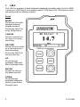
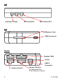
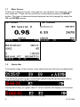
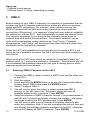
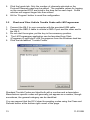
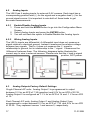
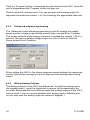
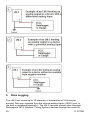
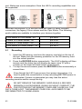
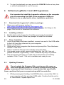
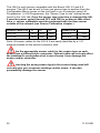
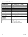
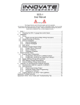
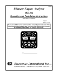
LM-2 Digital Air/Fuel Ratio Meter User Manual This manual assumes that firmware version 1.18 or later is installed. Warning! It is extremely important to avoid hot-plugging sensor connections. Do not connect or disconnect the sensor connectors while the unit is powered ON. The Oxygen Sensor used in this device gets very hot in operation. Do not touch the hot sensor. Do not let a hot sensor touch a combustible surface. Do not use the sensor with or near flammable liquids or gases. Failure to heed these warnings may result in severe burns, explosions or fires. When installed in the exhaust, the oxygen sensor MUST be connected and operating with the LM-2 whenever the car is running. An unpowered oxygen sensor will be quickly damaged when exposed to hot exhaust gases. 1 11-0122B TABLE OF CONTENT 1 LM-2 ......................................................................................................... 3 1.1 Main Screen ....................................................................................... 5 1.2 Status Bar ........................................................................................... 5 1.3 Configuration Menu Screen ............................................................... 7 2 Air/Fuel Ratio Setup ................................................................................. 8 2.1 Sensor Placement .............................................................................. 8 2.2 Sensor Calibration .............................................................................. 9 2.3 Calibration Schedule ........................................................................ 10 3 OBD-II .................................................................................................... 11 3.1 Selecting OBD-II Channels on the LM-2 .......................................... 11 3.2 Check Vehicle Trouble Codes on the LM-2 ..................................... 12 3.3 Clear Vehicle Trouble Codes on the LM-2 ....................................... 12 3.4 Selecting Channels with the LM Programmer software ................... 12 3.5 Check and Clear Vehicle Trouble Codes with LM Programmer ...... 13 3.6 OBD II connection diagnostic trace .................................................. 14 4 Analog Cable.......................................................................................... 14 4.1 RPM Input ........................................................................................ 14 4.1.1 Enable/Disable RPM ................................................................. 15 4.1.2 Configure RPM .......................................................................... 15 4.1.3 Attenuating a Tach Signal ......................................................... 16 4.2 Analog Inputs ................................................................................... 17 4.2.1 Enable/Disable Analog Inputs ................................................... 17 4.2.2 Wiring Analog Inputs ................................................................. 17 4.3 Analog Outputs Factory Default Settings ......................................... 17 4.3.1 Programming Analog Outputs .................................................. 18 4.3.2 Advanced output programming ................................................. 19 4.3.3 Wiring Analog Outputs .............................................................. 19 5 Data Logging .......................................................................................... 20 5.1 Recording ......................................................................................... 21 5.2 Log File Format ................................................................................ 22 5.3 Downloading Logs from Memory Card............................................. 22 5.4 Playback ........................................................................................... 22 6 Software (LogWorks 3 and LM Programmer) ........................................ 23 6.1 Download the Logworks 3 software package .................................. 23 6.2 Installing software............................................................................. 23 6.3 Driver Instalation .............................................................................. 23 6.4 Updating Firmware ........................................................................... 23 6.5 Changing Sensor Type .................................................................... 24 Appendix A: Specifications ............................................................................ 26 Appendix B: Limited Warranty ....................................................................... 27 Appendix C: Error Codes and Troubleshooting Tips .................................... 28 2 11-0122B 1 LM-2 The LM-2 is a single or dual channel wideband controller with a built-in OBD II scan tool, RPM input, four analog inputs, MTS serial I/O, SD memory card recording and two analog outputs. Front MODE Press once to cycle through channel display screens. Press and HOLD to enter Setup Menu. CANCEL Press to cancel out of menu or to stop recording. RECORD Press once to record or a second time to stop recording. Press and HOLD to force a new log. UP Scroll through available channels. Move through menu ENTER Accept an entry in the menu screen. DOWN Scroll through available channels. When in the Move through menu 3 11-0122B Left Inductive Clamp MTS Serial IN MTS Serial OUT Top SD Memory Card USB Connector Bottom Analog Cable Power OBD-II Connector Sensor Port # 1 4 Sensor Port # 2 (Enabled with the Dual Channel version) 11-0122B 1.1 Main Screen There are 3 different screen view options: one channel, two channels, and four channels. These can be cycled by momentarily pressing the MODE button. The type of channels being displayed can be changed by using the UP and DOWN arrows. One Channel Two Channels Four Channels 1.2 Status Bar The bottom edge of the screen is the status bar and will look something like this: The left most portion is the current time (which can be set via menu and is set automatically by LM Programmer). During Recording, an upper case ‘R’ and a counter will display on the lower left: Counting minutes and seconds of recording. 5 11-0122B Similarly, during playback a upper case ‘P’ and a counter will display: Counting elapsed time during playback. Note: If Recording does not start (see later section), also look here, the word “Card?” will appear if no SD card is detected when Record is selected. The word “Full!” will appear if you have either filled the SD card, or exhausted the available log names (see section on recording). Moving to the right, the next two indications are O2 sensor status, which can be one of the following: HW - Heater Warm-up Cal - Calibrating O2 - Reading O2 context (lambda over 8.something) L - Reading Lambda (or AFR) Ex - Error, Check Appendix E for error code meanings and trouble shooting tips Note: If the LM-2 is a single channel model, the second indication will be blank, not an error code. The next indicator, “R”, will appear when a) RPM is selected for logging/use (see menus) and b) an RPM signal is detected. Note, when RPM is enabled, but no RPM signal is detected, this symbol will appear in lower case (“r”). The “A” indicator means that the 4 Analog Inputs are selected for logging/Use (see menus). It is all or nothing. The display will be blank if disabled. The “O” indicates that an OBD-II connection is active. This indicator will blink at the relative ‘sample rate’, which will vary on the number of channels selected and the vehicle’s protocol. The display will be blank if the unit is not connected to an OBD-II port. The blinking “M” indicates that MTS serial data is being generated. This will blink at the relative MTS packet rate (for comparison with the O indicator). If the unit is not the “head” unit, then this will only blink when packets are being 6 11-0122B received via the Serial In connector. Last, “H” indicates that the unit is the MTS head unit. If the unit is not head this indicator will appear as a “-“ 1.3 Configuration Menu Screen To enter the Configuration Menu Screen press and hold the MODE button. Navigating the Menu: “ENTER” Accepts “CANCEL” Returns one menu level “MODE” Returns to Main Screen UP and DOWN arrows adjust selection or value “RECORD” has no effect When “MODE” is first pressed, the following choices appear: Display AFR or Lambda. Factory default setting is AFR. Calibrate Sensors - Free Air Calibrate ALL O2 sensors connected will be calibrated Fuel Type Setup – Change the AFR fuel type setting. Factory default setting is Gasoline (14.7.) RPM – Enable/Disable RPM and Configure RPM. Analog Inputs- Enable/Disable Analog Inputs and Configure Inputs. OBD-II - Configure Number of Channels (0-16), Channel Use, Get/Clear DTC codes Display in Metric/Imperial Units, and Start Trace File. Playback Log Reverse/Normal Display Set Date/Time - Set the current date/time Wideband Sensor Type Setup – Allows to select from the Bosch LSU 4.2 or LSU 4.9 sensor. Refer to “Changing Sensor Type” chapter. Note: Entering the Configuration Menus will stop recording and suspend MTS packet output 7 11-0122B 2 2.1 Air/Fuel Ratio Setup Sensor Placement Optimum bung placement will vary from application to application, but using the guideline below will ensure the longest sensor life with the most accurate readings. Using a bung is the preferred method for mounting the oxygen sensor in all applications. Weld the bung at least 24 inches downstream of the exhaust port outlet (after the collector), or 24 inches after the turbocharger if so equipped. The bung should be welded before the X or H pipe if so equipped. Using a clock as reference, mount the bung between the 9:00 o’clock and 3:00 o’clock position. Welding the bung in the lower section of the exhaust pipe can result in sensor damage caused by condensation making contact with the sensor’s internal heating element. A 1” bung (provided in the kit) will best protect the sensor. When fully threaded, the sensor’s tip will sit flush with the exhaust pipe, this does not adversely affect the readings. The bung should always be welded before the Catalytic Converter. Welding the bung after the catalytic converter will skew the readings toward lean. The skew in readings will vary with engine load and the efficiency of the catalytic converter. Leaded fuel and two stroke applications will reduce the sensor’s life. There are many other factors that dictate the sensor’s lifespan so it is impossible to predict it’s total longevity. Exhaust leaks, camshaft overlap, and open (shorty) exhausts will cause false lean readings at light engine loads. Typically, once the engine is under load and the exhaust gas volume increases, you will see accurate readings. When installed in the exhaust, the oxygen sensor must be connected to a powered, functional LM-2 (no error codes) whenever the engine is running. An un-powered sensor will be damaged in a short period of time when exposed to exhaust gas. Do not pre-warm the sensor before starting the engine, simply start the engine as normal. Allowing the sensor to pre-warm before starting the engine will increase the possibility of damaging the sensor from shockcooling. 8 11-0122B The maximum temperature of the sensor at the bung (the sensor mounting location) should not exceed 500 oC or 900 oF. If these temperatures are exceeded in your application you should install the Innovate Motorsports HBX-1 heat sink bung extender. (p/n 3729.) Alternatively you can also use the optional exhaust clamp (p/n 3728) to sample exhaust gases at the end of the tail pipe. Be aware that this method of sampling exhaust gas is prone to give false lean readings at light engine loads. As the O2 sensor measures the oxygen content of the exhaust gas to provide an accurate O2 reading, even a small pin-hole leak in a poorly welded sensor bung will affect the accuracy and performance of your O2 sensor. Remember, any deviation from the instructions provided for proper sensor installation will lead to inaccurate O2 readings. 2.2 Sensor Calibration Innovate Motorsports’ ‘Direct Digital’ wideband measurement technology allows you to calibrate the sensor to compensate for sensor wear and atmospheric pressure variances. This procedure takes just a few moments and it will ensure the most accurate readings throughout the oxygen sensor’s life. This procedure is required anytime a NEW oxygen sensor is installed. It is extremely important to avoid hot-plugging sensor connections. Do not connect or disconnect the sensor connectors while the unit is powered ON. The calibration procedure requires that the oxygen sensor be in free air, this means removed from the exhaust system completely. 1. With the LM-2 powered off, connect the oxygen sensor to the sensor cable and the other end to the sensor input on the LM-2. Single Channel: The active sensor port is #1 which is parallel to the power connection. Dual Channel: Both oxygen sensors may be connected to the unit at the same time or one at a time. 2. Connect the LM-2 to the cigarette power plug with the provided cigarette power adapter. 9 11-0122B 3. The sensor(s) will start warming up. The LM-2 will display WXX, where XX is the percentage of temperature reached. Notice the status bar displaying a ‘W’. 4. Once the unit stops indicating the sensor is warming up, it is time to trigger the calibration. Press and hold the MODE button until the Configuration Menu appears. Select ‘Calibrate Sensors’ and press the Enter button. 5. Confirm by selecting ‘Start Sensor Calibration’ and press the ENTER button. 6. The display will momentarily display ‘Cal’ and then it will switch to reading a percentage of oxygen. If the oxygen content now differs from 20.9% by more than 0.4%, repeat the calibration. 7. The LM-2 is calibrated and ready for use. The LM-2 must be powered by the cigarette adapter (12 volts) in order to properly heat the Oxygen sensor and measure Air/Fuel. If the unit is only connected to the OBDII port it will properly function as a scan tool, but not warm up the sensor. 2.3 Calibration Schedule Normally aspirated (daily driver) - Calibrate before installation of new sensor - Calibrate new sensor again after 3 month of use - Thereafter calibrate once a year or every 20,000 miles, whichever comes first Turbo Application, daily driver (tuned rich) - Calibrate before installation of new sensor - Calibrate new sensor again after 3 month of use - Thereafter calibrate twice a year or every 10,000 miles, whichever comes first Race Application - Calibrate before first installation of new sensor - Calibrate once per race weekend 10 11-0122B Dyno use: - Calibrate a new sensor - Calibrate every 2-3 days, depending on usage 3 OBD-II Before setting up your OBD-II channels it is important to understand that the number and type of channels selected have a dramatic effect on response speed and ECU connectivity. For example, older vehicles running the ISO9141 protocol will not deliver as many channels as newer vehicles running the CAN protocol. It is important to start with one channel, establish the connection with the ECU, then incrementally increase the channel count. The common symptoms for too many active channels can be seen as channel drop outs and/or disconnections. The channel selection can be optimized by designating certain channels as “Low Priority.” Channels designated as “Low Priority” will be queried less often which will allow more bandwidth for the high priority channels. When the LM-2 first establishes the connection to the vehicle’s ECU it will query the list of available channels, the LM-2 will then only allow a selection from this list. When moving the LM-2 from vehicle to vehicle is it important to reset the channel count to 1 and set the protocol to ‘Automatic’. This will allow the LM2 to reestablish the available channel list and give a starting point to which response speed can be evaluated. 3.1 Selecting OBD-II Channels on the LM-2 1. Connect the OBD-II cable to vehicle’s OBD-II port and the other end to the LM-2 2. Start the engine. 3. Press and hold the MODE button to go into the Configuration Menu Screen. Select OBD-II and press the ENTER button. 4. Select Configure OBD-II. 5. You will now be given the option to select a particular OBD II protocol or you can leave it on ‘Automatic’ which will scan all available protocol until it connects. Press ENTER. 6. Select the number of OBD II channels to read It is recommended to start off with 1 channel and slowly increase the number, evaluating the speed at which the ECU delivers data. Press ENTER. 7. You will now be able to scroll through all available channels and make your selection. Note: If you are connected the unit will filter and only display the available channels available by the ECU, otherwise the unit will display all OBD-II channels. Press ENTER. 11-0122B 11 8. Chose if the channel is Low or High Priority. Press ENTER to move to the next channel. 9. After all channels have been selected the unit will return to the main screen. It cannot be stressed enough, the number and type of channels selected will have a dramatic affect in response speed and ECU connectivity. 3.2 Check Vehicle Trouble Codes on the LM-2 1. Connect the OBD-II cable to vehicle’s OBD-II port and the other end to the LM-2 2. Do not start the engine, put the key in the accessory position. 3. To view your vehicle trouble codes press and hold the MODE button to go into the Configuration Menu Screen. 4. Select OBD-II and press the ENTER button. 5. Select “Get DTC’s”. A list (if any) of error codes will be displayed on the screen. You may scroll up and down the list using the arrows. 6. To see the specific meaning of the error code, select it and click ENTER. Click ENTER again to return to the list. 7. Press MODE or CANCEL to exit. 3.3 Clear Vehicle Trouble Codes on the LM-2 1. Connect the OBD-II cable to vehicle’s OBD-II port and the other end to the LM-2 2. Do not start the engine, put the key in the accessory position. 3. To clear your vehicle trouble codes press and hold the MODE button to go into the Configuration Menu Screen. 4. Select OBD-II and press the ENTER button. 5. Select Clear DTC Codes and press the ENTER button. 3.4 Selecting Channels with the LM Programmer software 1. Connect the LM-2 to your computer with the provided USB cable. Connect the OBD-II cable to vehicle’s OBD-II port and the other end to the LM-2. 2. Start the engine. 3. The LM Programmer application can be launched from Start->Programs>LogWorks3->LM Programmer from the Windows task bar. 4. The Inputs tab allows you to set the number of MTS channels to generate. 12 11-0122B 5. Click the Inputs tab. Only the number of channels selected on the Protocol/Channels page can be edited. The available values for logging on the connected ECU are listed in the drop list for each Input. Some vehicles will support larger lists than others. 6. Hit the ‘Program’ button to send the configuration. 3.5 Check and Clear Vehicle Trouble Codes with LM Programmer 1. Connect the LM-2 to your computer with the provided USB cable. 2. Connect the OBD-II cable to vehicle’s OBD-II port and the other end to the LM-2. 3. Do not start the engine, put the key in the accessory position. 4. The LM Programmer application can be launched from Start>Programs->LogWorks3->LM Programmer from the Windows task bar. 5. Click the tab labeled “Trouble Codes.” Standard Trouble Codes are listed both with a number and a description. Manufacturer specific codes will generally just appear as a number, though sometimes, the general category can be identified. You can request that the ECU clear the pending codes using the Clear and Refresh button at the bottom right corner of the page. 13 11-0122B 3.6 OBD II connection diagnostic trace In the rare situation where the LM-2 is not able to connect to the vehicle’s OBD-II protocol creating a trace file will greatly aid in diagnosing the problem. 1. Press and hold the MODE button to go into the Configuration Menu Screen. 2. Select OBD-II and press the ENTER button. 3. Use the ARROW buttons to scroll down to Start Trace File and press the ENTER button. A 't' will alternate (or stay steady) in the "O" spot on the status bar. 4. Connect the LM-2 to the vehicle’s OBD-II port. Wait one minute. 5. Wait one minute, then either press RECORD to stop, or select "Stop Trace File" from OBD-II menu. 6. A file named OBDIIxx.TXT will be saved on the SD card (xx counts up to 99). 7. E-mail this file along with the year, make, and model of the vehicle to the support staff at Innovate Motorsports 4 Analog Cable The provided analog cable has 14 stripped ends. The wire assignments are as follows: Analog Out 1 + (Lime Green) Analog Out 2 + (Brown/White) Analog Out 1 – (Yellow) Analog Out 2 – (Dark green) Analog In 1 + (Purple) Analog In 2 + (Grey) Analog In 1 – (Black) Analog In 2 – (Brown) Analog In 3 + (White) Analog In 4 + (Peach) Analog In 3 – (Red) Analog In 4 – (Orange) RPM + (Black/White) RPM – (Blue) 4.1 RPM Input The LM-2 has a direct tach signal input signal. This input can be used to feed a signal from the negative lead of a coil, ECU, negative lead of an injector, or ignition box (i.e. MSD 6AL). This tach signal can be feed to the RPM + (Black/White) wire. The negative wire (Blue) can be connected to ground if a tach signal is not being registered. Note: Ignitions running a multi-spark setup (i.e. MSD 6AL) must use the provided tach signal from the ignition box. 14 11-0122B 4.1.1 Enable/Disable RPM Enabling the RPM channel will allow you to display the channel on the LM-2 and log it on the SD memory card. Disabling the channel will do the exact opposite. 1. Press and hold the MODE button to go into the Configuration Menu Screen. 2. Select RPM and press the ENTER button. 3. You will now have the option to Enable/Disable RPM. 4.1.2 Configure RPM 1. Press and hold the MODE button to go into the Configuration Menu Screen 2. Select RPM and press the ENTER button. 3. Select Configure RPM and press the ENTER button. 4. You will now have the option of selecting the Tach input source, use the arrows to change the selection. 0 is the input from the Analog Cable, 1 is the input from the Inductive Clamp. Press ENTER. 5. You will now have the option to select the ‘Polarity.’ Rising Edge is the most common way to measure a tach signal. If you find that your readings are very erratic you should change this setting to Falling Edge. Press ENTER. 6. Select the RPM range. Options are 10230 RPM or 20460 RPM. Press ENTER. 7. Select Pulses per Rotation. Below are two tables to aid in your selection: Cylinder number and RPM calibrate number 4 Cyl engine Cylinder Pulses/Crank- Calibrate Comment Count Rotation Number 1 1/2 1 Use also when using inductive clamp on spark wire or power wire of COP system of 1 cylinder only for all cylinder numbers 2 1 2 Use also when using inductive clamp on spark wire or power wire of Waste spark coil of 1 cylinder only. Waste spark system: 1 coil for every 2 cylinders. 3 1-1/2 3 4 2 4 5 2-1/2 5 6 3 6 8 4 7 10 10 8 12 12 9 15 11-0122B Cylinder number and RPM calibrate number 2 Cycle and Rotary Engine Cylinder Pulses/Crank- Calibrate Comment Count Rotation # 1 1 2 Use also when using inductive clamp on spark wire or power wire of COP system of 1 cylinder only for all cylinder numbers Also use for rotary engine. 2 2 4 Use also when using inductive clamp on spark wire or power wire of Waste spark coil of 1 cylinder only. Waste spark system: 1 coil for every 2 cylinders. 3 3 6 4 4 8 5 5 8 6 6 9 8. Once the selection is made press ENTER. You will be brought back to the main screen. 4.1.3 Attenuating a Tach Signal The problem of an erratic tach signal happens if there is a lot of ringing at high voltages. To counteract this, it is sometimes necessary to attenuate the tach signal by about 30dB or so. This is accomplished with a 100k variable potentiometer which can be purchased at Radio Shack or any electronics store. Wiring 1. Connect the tach signal to terminal A. 2. Connect terminal B to the tach signal input of the LM-2’s analog cable which is the Black wire with a White stripe. 3. Connect the terminal C to Ground. (Do not connect this to the Blue tach signal ground on the LM-2’s analog cable.) Tuning RPM 1. Turn the pot all the way to the right (until no RPM is registered). 2. Start turning the pot to the left and stop when you start registering a tach signal and the LM-2 displays an 'R' on the status bar. 16 11-0122B 4.2 Analog Inputs The LM-2 has 4 analog inputs for external 0-5V sensors. Each input has a corresponding positive lead (+) for the signal and a negative lead (–) for the ground signal source. It is important to wire both of these leads to get accurate measurements. 4.2.1 Enable/Disable Analog Inputs 1. Press and hold the MODE button to go into the Configuration Menu Screen. 2. Select Analog Inputs and press the ENTER button. 3. You will not have the option to Enable/Disable the Analog Inputs. 4.2.2 Wiring Analog Inputs The LM-2’s inputs are differential. A differential input does not measure a signal relative to electrical ground. Instead it measures the relative voltage between two signals. That is, it does not measure the '+' signal in relationship to ground, but in relationship to the '-' signal. It measures the 'difference' between them. The following diagrams better illustrate the correct way to wire in external sensors. Please note that the + lead is signal positive, NOT power. 4.3 Analog Outputs Factory Default Settings Single Channel A/F units: Analog Output 1 is programmed to output between 0 V for an AFR of 7.35 (gasoline) and 5.0V for an AFR of 22.39. Analog Output 2 is configured as 1.1 V for an AFR of 14 and .1 V for an AFR of 15. Dual Channel A/F units: Analog Output 1 and Analog Output 2 are programmed to output between 0 V for an AFR of 7.35 and 5.0V for an AFR of 22.39. They represent sensor 1 and sensor 2, respectively. 17 11-0122B 4.3.1 Programming Analog Outputs 1. Connect the LM-2 to your computer with the provided USB cable. 2. Power up the LM-2. 3. Launch LM Programmer. The LM Programmer application can be launched from Start->Programs->LogWorks3->LM Programmer from the Windows task bar. 4. Select one of the Analog output tabs. The Analog output page looks like this: This shows the analog output voltages versus Lambda for one of the two analog outputs. The graph display is automatically scaled to the selected voltages. For each output you can specify a minimum and maximum lambda value and the associated voltages. Below the minimum and above the maximum lambda values the output voltages stay constant at the associated programmed voltage. By selecting the ‘use Air-Fuel-Ratio’ button you can program the curve by AFR instead of Lambda. This does not change the programming, only the representation of the data. When programming by AFR the LM Programmer converts the number to Lambda before programming the LM-2. 18 11-0122B Click the ‘Program’ button to download the new data into the LM-2. Once the unit is programmed the ‘Program’ button will grey out. Note for Dual A/F channel units: You can program each analog output to represent the data from sensor 1 or 2 by selecting the appropriate radio box. 4.3.2 Advanced output programming The ‘Advanced’ button allows programming to set the analog out update speed and the voltage output during sensor Warm-up and Error Condition. The factory defaults of the analog outputs is to update the outputs 1/12 of a second. The factory default voltage output is set for 0 volts for both the Warm-up and Error Condition. When setting the LM-2 to the slower response speed settings the measured mixture data will be averaged over the response time setting before being output. 4.3.3 Wiring Analog Outputs The analog outputs on the LM-2 are differential. As with the analog inputs, the negative lead (-) must be connected to ground for the readings to be accurate. Below are the three different ways the analog outputs of the LM-2 can be wired. If you are unsure whether your analog input is differential or not you may wire the analog output as shown in diagram 1. 19 11-0122B 5 Data Logging The LM-2 can record up to 32 channels of information at 12 times per second. Data can originate from the internal analog inputs, OBD-II port, or the built-in wideband channel(s). The LM-2 can also accept other Innovate Motorsports’ MTS (Modular Tuning System) devices through the serial IN 20 11-0122B port. Below are some examples of how the LM-2’s recording capabilities can be expanded. Innovate Motorsports’ MTS devices have two types of serial interface connectors, the legacy 2.5mm stereo and the 4 pin Molex. The following patch cables are available to interface your devices together: 4 Pin Molex to 4 Pin Molex - 4ft p/n 3846 2.5mm to 2.5mm Stereo - 4ft p/n 3760 2.5mm to 2.5mm Stereo - 6in p/n 3789 4 Pin Molex to 2.5mm Stereo - 4ft p/n 3812 5.1 Recording 1. Insert the SD memory card into the memory card slot on the top of the unit. Make sure the memory protection on the SD memory card is in the unlock position. 2. Press the RECORD button momentarily. The LM-2’s display will then inverse and the status bar will display an upper case ‘R’ with a counter on the lower left hand corner of the screen. 3. To stop the record session press the RECORD button momentarily a second time. Even though the LM-2 can recover from power interruption, it is best to press the record button to stop recording BEFORE power is interrupted. If power is interrupted you may lose the active recording session and/or corrupt the log. DO NOT REMOVE THE MEMORY CARD WHILE A RECORD SESSION IS IN PROGRESS. DOING SO MIGHT CORRUPT THE FILE SYSTEM ON THE MEMORY CARD AND CAUSE ALL THE DATA TO BE LOST. THE MEMORY CARD WILL ALSO NEED TO BE REFORMATTED TO WORK AGAIN. 21 11-0122B 5.2 Log File Format When RECORD is first activated, a file is created and session is created. Each subsequent recording will create an additional session within the file log. To force a new file log press and hold the RECORD button until “New!” is displayed on the lower left hand corner of the status bar. A new log file is automatically created if MTS devices are added or removed from the serial chain , or if channels are enabled/disabled on the LM-2. The naming convention for the log file is: mmddyyXX.d32 These are the month, day, and year that the file is created. The XX is to accommodate multiple files on the same day (counting begins at “00”). 5.3 Downloading Logs from Memory Card Note: An SD memory card reader is necessary to retrieve logs from the memory card. The logs can not be downloaded through the LM-2.. 1. Remove the memory card from the LM-2 and insert it in your SD memory card reader. 2. Launch LogWorks 3. The LogWorks 3 application can be launched from Start->Programs->LogWorks3->LogWorks3 from the Windows task bar. 3. Click on File->Import/Download->Import LM-2 Log. 4. A window will pop up which will allow you to select the desired log from the memory card. Click Open. 5.4 Playback 1. Press and hold the MODE button to go into the Configuration Menu Screen. 2. Select Playback log and press the ENTER button. 3. A list of available logs present on the memory card will be displayed. Make your selection and press the ENTER button. Note: Depending on the size of the log the next screen some time to appear. 4. A list of available sessions will be displayed. Make your selection and press the Enter button. 5. The selected session will now start playing. The status bar will display an upper case ‘P’ and a counter on the lower left hand corner of the screen. Note: While the session is being played back you can press the MODE button to cycle through the different display screens and you may also press the ARROW buttons to change the displayed channels. 22 11-0122B 6. To stop the playback you may press the CANCEL button at any time or allow the playback to run it’s course. 6 Software (LogWorks 3 and LM Programmer) It is important to install the Logworks software on the computer prior to connecting the LM-2 to the computer’s USB port. Failure to do so may lead to driver installation problems. 6.1 Download the Logworks 3 software package 1. Open your web browser and go to: http://www.innovatemotorsports.com/support.php 2. The LogWorks 3 software download will be the very first thing on the page, click the link to download the software. 6.2 Installing software 1. Double click on the Logworks 3 installer previously downloaded. 2. The installer will start, follow the prompts to install the software. 6.3 Driver Instalation 1. Once the software has been installed, connect one end of the USB cable to the LM-2 and the other end to your computer. 2. Power up the LM-2. 3. Windows will now recognize the device and prompt the “New Hardware Wizard.” Click Next. 4. Select “Install the Device Automatically” and click Next. 5. A progress screen might appear indicating that the LM-2 has not passes Windows Logo testing – Click “Continue Anyway” to proceed. 6. The last screen will inform you that the unit has been successfully installed. Click “Finish.” The unit is installed and ready to use. 6.4 Updating Firmware Do not update the firmware if the versions are the same or older than already loaded. A firmware update should only be necessary if there has been a new release that specifically fixes a problem that you are experiencing with the controller. 1. While pressing and holding the MODE button, connect the LM-2 to your computer with the provided USB cable. Confirm that the unit is in “Boot Mode,” repeat steps if not. 11-0122B 23 2. Connect the LM-2 to 12V power. 3. Launch LM Programmer. The LM Programmer application can be launched from Start->Programs->LogWorks3->LM Programmer from the Windows task bar. 4. Once connected , LM Programmer will display the current version of the firmware that is installed in the LM-2. Do not update the firmware if the versions are the same. A firmware update should only be necessary if there has been a new release. 5. On the very first tab of LM Programmer you will see a button labeled “Update Firmware,” click this button. 6. Select the firmware file with the dld extension. 7. Do not disconnect the unit from the computer until the firmware progress screen completely disappears. Once finished you may disconnect the unit from the computer and exit out of the software. Note: Performing a firmware upgrade to the LM-2 clears all calibration data. Perform a sensor calibration on the next power up after a firmware upgrade. Be sure to have the O2 sensor outside of the exhaust (free air.) 6.5 Changing Sensor Type Note: The LM-2 must be running firmware version 1.18 or later and LM Programmer 4.0 or later to access the sensor type menu. 24 11-0122B The LM-2 is multi sensor compatible with the Bosch LSU 4.2 and 4.9 sensors. The LM-2 can be set to from one sensor type to another from the Configuration Menu screen on the unit itself or on a computer using LM Programmer. In LM Programmer, the “Sensor Type to use” setting can be found in the ‘Info’ tab. Once the sensor type selection is changed the LM2 must be power cycled (turned OFF and ON) for setting to take effect. Also, a sensor calibration must be performed with the new sensor outside of the exhaust (see Sensor Calibration chapter.) 18ft Sensor Cable P/N 3ft 8ft LSU 4.2 3843 3810 3828 LSU 4.2 3737 LSU 4.9 3890 3887 3889 LSU 4.9 3888 Sensor P/N Note: All sensor cables for the LSU 4.9 are easily identified by a ‘4.9’ marking molded on the sensor connector side. Use the appropriate sensor cable for the sensor type as each sensor has a different style connector. Spliced cable can not only affect the wideband’s performance but in worst cases it can damage the sensor and/or controller. Selecting the wrong sensor type to the sensor being used will not only give you erroneous readings and/or errors. It can also permanently damage the sensor. 25 11-0122B Appendix A: Specifications Power Power requirements Serial Communication Serial Port Speed Packet/Logging Speed Sample Resolution OBD-II (US Spec vehicles) Number of Channels Supported protocols USB Specifications Protocol Version Supported OSs Temperature Max Operating Temperature Recording Memory Card 26 Single Channel 8-14 Volt / 2 A (max, 1 A nominal) Dual Channel 8-14 Volt / 4 A (max, 2 A nominal) 19.2 kbit/sec 81.92 msec/sample packet 10 bits (0..5V at 0.1% resolution) 16 (max) ISO 157650 (CAN), J1850PWM, J1850VPW, ISO 9141, ISO 14230 (KWP2000) 2.0 Windows 2000, XP, Vista, 7, and 8 -20 to +80 deg Celsius SD 4GB or smaller. File format : FAT or FAT16 (SDHC cards are not compatible) 11-0122B Appendix B: Limited Warranty LIMITED WARRANTY Innovate stands behind the quality of its products. Innovate makes the following warranty to purchasers of its products: All new Innovate products carry a one year warranty from the date of purchase. If proof of purchase cannot be provided, warranty will be determined by date of manufacture. When Warranty Void This warranty shall terminate and Innovate shall have no obligation pursuant to it if (i) your Innovate product has been modified or repaired in a manner not previously authorized by Innovate in writing, (ii) the identification markings on your Innovate product have been removed, defaced, or altered; (iii) your Innovate product was subjected to accident, abuse, shipping damage, or improper use; (iv) your Innovate product was not used or configured as specified in the product manual; or (v) your Innovate product was subjected to operating conditions more severe than those specified in the product manual. Exclusions From This Warranty Oxygen Sensors are excluded from this warranty. Repairs Under This Warranty In the unlikely event that your Innovate hardware product should prove defective during the warranty period, contact Innovate Customer Support at www.innovatemotorsports.com for a return material authorization (RMA). Products returned for service must be securely packed to prevent damage and shipped charges pre paid, along with proof of purchase and the return material authorization number, to the Innovate repair location as instructed by Customer Service. Innovate within a reasonable amount of time from its receipt of your product so shipped, will ship to you, at its option, the repaired product or a new or reconditioned product of comparable or greater specified functionality. All repaired or replacement products shall be warranted for the remainder of the original product warranty. Disclaimer INNOVATE MAKES NO OTHER EXPRESS OR IMPLIED WARRANTY WITH RESPECT TO YOUR INNOVATE PRODUCT OTHER THAN THE LIMITED WARRANTY SET FORTH ABOVE. No Innovate dealer, agent, or employee is authorized to make any modification, extension, or addition to this warranty, unless enforceable or unlawful under applicable law, INNOVATE DISCLAIMS ALL IMPLIED WARRANTIES, INCLUDING THE IMPLIED WARRANTIES OF MERCHANTABILITY, NONINFRINGEMENT, AND FITNESS FOR A PARTICULAR PURPOSE, AND THE LIABILITY OF INNOVATE, IF ANY, FOR DAMAGES RELATING TO ANY ALLEGEDLY DEFECTIVE PRODUCT SHALL UNDER ANY TORT, CONTRACT, OR OTHER LEGAL THEORY BE LIMITED TO THE ACTUAL PRICE PAID FOR SUCH PRODUCT AND SHALL IN NO EVENT INCLUDE INCIDENTAL, CONSEQUENTIAL, SPECIAL, OR INDIRECT DAMAGES OF ANY KIND EVEN IF INNOVATE IS AWARE OF THE POSSIBILITY OF SUCH DAMAGES. Some states do not allow limitations on how long an implied warranty lasts or the exclusion or limitation of incidental or consequential damages, so the above limitations or exclusions may not apply to you. 27 11-0122B Appendix C: Error Codes and Troubleshooting Tips Error Code Error 1 Error Message Heater circuit shorted Error 2 Heater circuit open Error 3 Error 4 Error 5 Likely Root Cause Fix 1 Short in sensor cable. 2. Short in sensor 1. Check sensor cable for physical damage, replace if needed. 2. Replace sensor. 1. Damaged sensor cable or sensor. 2. Sensor not fully seated and locked into position on sensor cable. 3. Senor cable not connected to the right sensor port on the LM-2. Pump cell 1. Short in sensor circuit shorted cable 2. Short in sensor 3. Sensor calibration incorrect Pump cell 1. Damaged sensor circuit open cable or sensor. 2. Connectors not fully seated 3. Sensor calibration incorrect Reference cell circuit shorted Reference cell circuit open 1. Short in sensor cable 2. Short in sensor 1. Damaged sensor cable or sensor. 2. Connectors not fully seated Error 7 Error 8 System error System error Sensor Timing error (typically a damaged sensor). 1. Sensor over-heating or over-cooling (error condition only occurs at wide open throttle ) Error 9 Supply Voltage too low Error 6 28 2. Sensor is damaged Supply voltage too low for sensor regulation 1. Verify that all sensor connectors are fully seated and locked into position. 2. Verify that the sensor cable is connected to the right sensor port on the LM-2. 3. Replace sensor 4. Check sensor cable for physical damage, replace if needed. 1. Check sensor cable for physical damage, replace if needed. 2. Replace sensor. 3. Perform sensor recalibration. 1. Verify that all sensor connectors are fully seated and locked into position. 2. Perform sensor calibration 3. Check sensor cable for physical damage, replace if needed. 4. Replace sensor. 1. Replace sensor cable. 2. Replace sensor. 1. Verify that all sensor connectors are fully seated and locked into position. 2. Replace sensor. 3. Replace sensor cable. Reboot LM-2 by cycling power. 1. Perform sensor calibration. 2. Move sensor bung as far downstream as possible. 3. Add an HBX-1 (p/n 3729) to isolate the sensor from the pipe. 4. Replace sensor. 1. Verify you have 12V at your power source and the circuit can support a 3 amp draw. 11-0122B