Download IPE1000-U

Transcript
Programmable Interpolation Unit
IPE1000-U
User Manual
Gesellschaft für
Mikroelektronikanwendung Chemnitz mbH
Zwickauer Straße 227
D-09116 Chemnitz, Germany
Phone:
Fax::
Internet:
Email:
+49 371 33 77 - 0
+49 371 33 77 272
www.gemac-chemnitz.de
[email protected]
[email protected]
Date: 25.05.05
Page 1 of 13
Title:
User manual - IPE1000-U
Name of Document:
46500-HB-1-4-E-IPE1000-U.pdf
Revision History
Date
16.12.2003
22.06.2004
02.07.2004
11.03.2005
25.05.2005
Revision
1.0
1.1
1.2
1.3
1.4
Changing
First version
Input connector pinning
Output signal description, Soldering Jumper J10
Several changings
Dimensions added
© Copyright 2005 GEMAC mbH
This document is subject to alterations without any notice.
We constantly work to further develop our products. We reserve any changes of scope of delivery in shape,
equipment and technology to ourselves. No claim can be the details, illustrations and descriptions in this
document. Any kind of duplication, reprocessing and translation of this document as well as excerpts from it
requires the written permission of the GEMAC mbH.
All rights according to the copyright remain explicitly reserved for GEMAC mbH.
Gesellschaft für
Mikroelektronikanwendung Chemnitz mbH
Zwickauer Straße 227
D-09116 Chemnitz, Germany
Phone:
Fax::
Internet:
Email:
+49 371 33 77 - 0
+49 371 33 77 272
www.gemac-chemnitz.de
[email protected]
[email protected]
Date: 25.05.05
Page 2 of 13
Title:
User manual - IPE1000-U
Name of Document:
46500-HB-1-4-E-IPE1000-U.pdf
1
Contents
1
CONTENTS .......................................................................................................................................... 3
2
OVERVIEW........................................................................................................................................... 4
3
INPUT SIGNALS................................................................................................................................... 5
3.1
3.2
3.3
4
OUTPUT SIGNALS............................................................................................................................... 7
4.1
4.2
5
CONNECTION OF A MEASURING SYSTEM ............................................................................................. 5
SIGNAL CORRECTION ........................................................................................................................ 6
REFERENCE SIGNAL.......................................................................................................................... 6
OUTPUT SIGNALS RS422 .................................................................................................................. 7
ERROR SIGNAL ................................................................................................................................. 7
INTERPOLATION RATE....................................................................................................................... 7
5.1
5.2
INTERVAL TIME / MAXIMUM INPUT FREQUENCY.................................................................................... 8
GLITCH FILTER ................................................................................................................................. 8
6
SPECIFICATIONS ................................................................................................................................ 9
7
CONFIGURATION OF THE SWITCHES AND CONNECTORS ........................................................... 10
7.1
7.2
7.3
7.4
7.5
7.6
7.7
8
EXTRUDED ALUMINIUM HOUSING IP20 ............................................................................................. 10
DIE-CAST BOX HOUSING IP65 ......................................................................................................... 10
DIL-SWITCH .................................................................................................................................. 10
INTERPOLATION RATE ..................................................................................................................... 10
MINIMUM EDGE DISTANCE AT THE OUTPUTS ...................................................................................... 11
SERVICE CONNECTOR SPI .............................................................................................................. 11
LED.............................................................................................................................................. 11
COMPONENT MOUNTING DIAGRAM................................................................................................ 12
8.1
8.2
SOLDERING JUMPER SOLDER SIDE ................................................................................................... 12
DIMENSIONS................................................................................................................................... 13
Gesellschaft für
Mikroelektronikanwendung Chemnitz mbH
Zwickauer Straße 227
D-09116 Chemnitz, Germany
Phone:
Fax::
Internet:
Email:
+49 371 33 77 - 0
+49 371 33 77 272
www.gemac-chemnitz.de
[email protected]
[email protected]
Date: 25.05.05
Page 3 of 13
Title:
User manual - IPE1000-U
Name of Document:
46500-HB-1-4-E-IPE1000-U.pdf
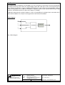
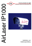
2
Overview
The programmable interpolation unit IPE1000-U has been designed for connection to incremental position
and angle measuring systems with sine-shaped output signals with a 90° phase shift. It can be operated at a
large number of transducer systems working according to the most varied measuring principles. With a
maximum interpolation rate of 1000 the IPE1000-U is capable to split the input signal period into up to 1000
segments. An RS422 interface for square wave outputs is available.
Proprietary automatic gain and offset control, as well as the possibility of a analogue phase correction of the
internal GC-IP1000 ensure a high measuring precision under industrial conditions.
Block diagram
Sin
Cos
GC-IP1000
RS422-interface
Ref
Fig. 1 Block diagram
Gesellschaft für
Mikroelektronikanwendung Chemnitz mbH
Zwickauer Straße 227
D-09116 Chemnitz, Germany
Phone:
Fax::
Internet:
Email:
+49 371 33 77 - 0
+49 371 33 77 272
www.gemac-chemnitz.de
[email protected]
[email protected]
Date: 25.05.05
Page 4 of 13
Title:
User manual - IPE1000-U
Name of Document:
46500-HB-1-4-E-IPE1000-U.pdf
3
Input Signals
The input signals of the IPE1000-U are analogue voltages (sine/cosine), which have a sine-shaped
dependency on the measured value (position or angle). The phase shift between those two analogue
voltages is 90°, related to one period of the scale. A third input signal serves the zero or reference point of
the scale as a reference signal for determining. All the three input signals are processed as differential or
single ended signals. Another version of the device with current inputs is also available (IPE1000-I).
0,5Vpp
1Vpp
sin
-sin
cos
-cos
sin
cos
0
90
180
270
360
450
540
630
720
Fig. 2 Input signals differential
3.1
0
90
180
270
360
450
540
630
720
Fig. 3 Input signals single-ended
Connection of a Measuring System
difference signal Sin = SinP-SinN
angle 0°
Udiff Peak to Peak
SinP
SinN
90° phase shift
Udiff Peak to Peak
CosP
CosN
difference signal Cos = CosPCosN
Fig. 4
G1
G0
open
open
closed
closed
closed
open
closed
open
1)
2)
Gain
(nominal)
19.5
16.25
13.45
1.95 2)
Input voltage for differential Input voltage UDiff
1)
input
(nominal)
50mVpp
100mVpp
60mVpp
120mVpp
72mVpp
145mVpp
0.5Vpp
1Vpp
at each of the inputs SINP,
Default value
Input voltage range for
UDiff
80 mVpp ... 120 mVpp
96 mVpp ... 144 mVpp
145 mVpp ... 174 mVpp
0.8Vpp ... 1.2Vpp
maximum
signal offset
±10mV
±12mV
±14.5mV
±100mV
SINN, COSP, COSN
See also chapter 8.1
Gesellschaft für
Mikroelektronikanwendung Chemnitz mbH
Zwickauer Straße 227
D-09116 Chemnitz, Germany
Phone:
Fax::
Internet:
Email:
+49 371 33 77 - 0
+49 371 33 77 272
www.gemac-chemnitz.de
[email protected]
[email protected]
Date: 25.05.05
Page 5 of 13
Title:
User manual - IPE1000-U
Name of Document:
46500-HB-1-4-E-IPE1000-U.pdf
3.2
Signal Correction
The input signals are subject to the internal automatic gain and offset control of the IP1000, which is
patented by GEMAC. The amplitude controller is specified for a control range of ±20% of nominal input
voltage. The offset of the external signals must not exceed a value of ±10% of nominal input voltage. The
phase shift of the input signals can be adjusted statically by the internal potentiometer in a range of ±6° or
±12° via SPI. There are two measuring points (MP1 and MP2) for testing the signals. The signal at each of
those measuring points should have an amplitude of 2.0VPP and an offset of 2.275V refering to Ground.
For achieving the best interpolation performance, the gain-offset-controller needs approximately 20 signal
periods for reaching a steady state. Until this time, the input signal frequency must not exceed 50% of the
specified maximum signal frequency (please refer to chapter 5.1).
For reaching the highest accuracy of the gain-offset regulation the phase should adjust. This will be very
important if high interpolation rates are used.
3.3
Reference Signal
A third output of the measuring system - typically called reference, index point or zero point signal – will be
considered to be activated, if the difference of the signals at the REFP and REFN pins becomes bigger than
the positive hysteresis voltage VRPH and will be considered to be deactivated if this voltage becomes smaller
than the negative hysteresis voltage VRPL.
REFN
REFP
respectively:
VRP = REFP - REFN
VRPH
inactive
VRPL
active
0V
inactive
Fig. 5
URPL (typ.) = -30mV
URPH (typ.) = +30mV
If a sensor without reference signals is used, defined levels on pins REFP and REFN are necessary to set
the index point always active or always inactive.
Reference signal at the output
active in each period
LJ 19: b-c
LJ18: open
R11: placed
Gesellschaft für
Mikroelektronikanwendung Chemnitz mbH
Zwickauer Straße 227
D-09116 Chemnitz, Germany
Phone:
Fax::
Internet:
Email:
Reference signal at the output
inactive
LJ 19: a-b
LJ18: open
R11: placed
+49 371 33 77 - 0
+49 371 33 77 272
www.gemac-chemnitz.de
[email protected]
[email protected]
Date: 25.05.05
Page 6 of 13
Title:
User manual - IPE1000-U
Name of Document:
46500-HB-1-4-E-IPE1000-U.pdf
4
Output Signals
4.1
Output Signals RS422
The output signals are phase shifted square wave sequences (known by incremental measuring
transducers). They can be counted in a single or quadruple way. A synchronous reference pulse will be
generated when the angle of 0° (refer also to Fig. 3) is passed through and when the analogue differential
input voltage between REFP and REFN exceeds the positive comparator hysteresis level. If the differential
input voltage is permanently above this level, the reference pulse will be generated once during every signal
period.
A
/A
B
/B
OREF
≥tpp
tpp: Minimum interval time
edge distance
Fig. 6 Output signals
For generating a reference pulse at the output and the exact assignment of the signals A, B and OREF it is
necessary to pass a Sin/Cos-period (for finding the zero degree angle). That status will be signalized by a
green Valid-LED (LED 3, looked status). In the case of an error the red Error-LED (LED 2) is switched on
and the green Valid-LED is switched off. An external reset pulse with a minimum length of 3µs will restart
the GC-IP1000. To get the locked status again a further Sin/Cos-period is needed.
In case of selected interpolation rates 125 and 250-fold the assignment of A, B and OREF can not be
guaranteed.
4.2
Error Signal
An error signal will be generated if the input signals are plausible no longer. The error signal will also be
generated if the input frequency is so high that the square-wave signals are unable to follow, and/or when
the maximum input frequency is exceeded.
If the error signal was activated, and/or if one of the error bits was set in the result register, the present
measuring result and all the following results would have to be discarded. Following elimination of the cause
of the error and a reset of the error bit, the reference point has to be passed by for absolute value
measurements once again!
5
Interpolation Rate
The interpolation rate can be set at 1000, 800, 500, 400, 250, 200, 125 and 100. The interpolation rate as
defined for the purposes of this application is the number of increments into which one sine period of the
input signal is divided. This also corresponds to the number of edge changes on the A/B output signals per
input signal period. This means that the number of square-wave periods at the A and B outputs totals 1/4 of
the interpolation rate per input signal period.
In the case that a standard interpolation counter or quadrature decoder is connected to the A/B outputs, this
has to work in "quadruple evaluation" mode in order to achieve the full interpolation rate.
Gesellschaft für
Mikroelektronikanwendung Chemnitz mbH
Zwickauer Straße 227
D-09116 Chemnitz, Germany
Phone:
Fax::
Internet:
Email:
+49 371 33 77 - 0
+49 371 33 77 272
www.gemac-chemnitz.de
[email protected]
[email protected]
Date: 25.05.05
Page 7 of 13
Title:
User manual - IPE1000-U
Name of Document:
46500-HB-1-4-E-IPE1000-U.pdf
5.1
Interval Time / Maximum Input Frequency
The interval time (IT) respectively the minimum edge distance (tPP) at the output signals can be adjusted
using the same DIL-Switch as for the interpolation rate. This is possible from 1/fosc to 128/f osc in binary steps.
The following table shows the maximum input frequencies under consideration of the interval times.
Clock frequency example
IR
1000
250
IT
1
2
4
8
16
32
64
128
1
2
4
8
16
32
64
128
tpp
45ns
91ns
181ns
363ns
727ns
1.4µs
2.9µs
5.8µs
45ns
91ns
181ns
363ns
727ns
1.4µs
2.9µs
5.8µs
fmax
19k
10k
5k
2.5k
1.2k
600
300
150
80k
40k
20k
10k
5k
2.5k
1.2k
600
IR
800
200
fOSZ = 22MHz
tpp
fmax
1 45ns
25k
2 91ns 12.5k
4 181ns
6.2k
8 363ns
3.1k
16 727ns
1.5k
32 1.4µs
775
64 2.9µs
380
128 5.8µs
190
1 45ns 100k
2 91ns
50k
4 181ns
25k
8 363ns 12.5k
16 727ns
6.2k
32 1.4µs
3.1k
64 2.9µs
1.5k
128 5.8µs
775
IT
f maxCNT = 110kHz
IR
IT
tpp
1 45ns
2 91ns
4 181ns
500
8 363ns
16 727ns
32 1.4µs
64 2.9µs
128 5.8µs
1 45ns
2 91ns
4 181ns
125
8 363ns
16 727ns
32 1.4µs
64 2.9µs
128 5.8µs
fmax
40k
20k
10k
5k
2.5k
1.2k
600
300
110k
80k
40k
20k
10k
5k
2.5k
1.2k
IR
400
100
IT
1
2
4
8
16
32
64
128
1
2
4
8
16
32
64
128
tpp
45ns
91ns
181ns
363ns
727ns
1.4µs
2.9µs
5.8µs
45ns
91ns
181ns
363ns
727ns
1.4µs
2.9µs
5.8µs
fmax
50k
25k
12.5k
6.2k
3.1k
1.5k
775
380
110k
100k
50k
25k
12.5k
6.2k
3.1k
1.5k
These values apply on condition of an adjusted phase between the input signals and a steady state of the
internal gain-offset-controller. Until this time, the input frequency must not exceed 50% of the specified
maximum frequency.
5.2
Glitch Filter
In order to avoid permanent toggling of the downstream counters as a result of analogue noise of the input
signals while the measuring system is in standstill, a digital filter can be optionally activated for the squarewave outputs (pin / bit GFE). In such a case, the minimum edge distance at the output (tpp) is then
automatically set at 1024/f osc while the measuring system is in standstill or at smaller input frequencies.
Note that in the switching range to the automatic activation / deactivation of this filter, the A/B output signals
are not speed-proportional in each case!
LJ10 - jumper for glitch filter
open
closed
description
glitch filter active
glitch filter inactive
For finding the jumper position please refer to chapter 8.
Gesellschaft für
Mikroelektronikanwendung Chemnitz mbH
Zwickauer Straße 227
D-09116 Chemnitz, Germany
Phone:
Fax::
Internet:
Email:
+49 371 33 77 - 0
+49 371 33 77 272
www.gemac-chemnitz.de
[email protected]
[email protected]
Date: 25.05.05
Page 8 of 13
Title:
User manual - IPE1000-U
Name of Document:
46500-HB-1-4-E-IPE1000-U.pdf
6
Specifications
Recommended Operating Conditions
Supply voltages
Supply current
Operating case temperature
MIN
4.75
Analogue Input Specifications
Input frequency range SIINP,SINN,COSP,COSN
Phase offset between SIN and COS
Peak to peak input voltage SINN ⇔ SINP / COSN ⇔ COSP
Phase deviation
Oscillator frequency
Reset Specifications
Reset impulse length
MIN
3
NOM
MAX
Unit
µs
Interpolation
Input frequency range
Automatic gain control range
Automatic offset control range
MIN
0
NOM
MAX
fosz / 96
Unit
kHz
Interpolation Rates
Minimum interval time A/B - Signals
Interpolation accuracy
Propagation delay counter
Propagation delay square-wave outputs (A/B/OREF)
Other characteristics
Degree of protection (depends on the housing)
Connector
Dimensions
Gesellschaft für
Mikroelektronikanwendung Chemnitz mbH
Zwickauer Straße 227
D-09116 Chemnitz, Germany
Phone:
Fax::
Internet:
Email:
NOM
5.0
130
MAX
5.25
MIN
NOM
0.8
±8
90
1.0
±10
20
MAX
400
-20
85
1.2
±12
±20%
±10%
20 / 25 / 40 / 50 / 80 / 100 / 160 / 200
1 / fosz
128 / fosz
±0.6
±1
90 / fosz
122 / fosz
Extruded aluminium
housing
IP20
Sub-D 15 pin
55mm x 80mm x 20mm
+49 371 33 77 - 0
+49 371 33 77 272
www.gemac-chemnitz.de
[email protected]
[email protected]
Date: 25.05.05
Page 9 of 13
Unit
V
mA
°C
Unit
kHz
°
Vpp
°
MHz
related to nom.
amplitude
ns
Inc.
ns
ns
die-cast box housing
IP65
Round plug 9- and 12pin
100mm x 66mm x 50mm
Title:
User manual - IPE1000-U
Name of Document:
46500-HB-1-4-E-IPE1000-U.pdf
7
Configuration of the Switches and Connectors
It is necessary to open the unit for configuration. This can be done by open the screws at both sides. The
cover can be lift off now.
7.1
Extruded Aluminium Housing IP20
Signal input - Sub-D 15-pin female
Pin No.
1
2
3
4
5
6
7
8
9
10
11
12
13
14
15
7.2
Signal output - Sub-D 15-pin male
Signal
SINP
0VDC
COSP
+5VDC
Pin No.
1
2
3
4
5
6
7
8
9
10
11
12
13
14
15
REFN
SINN
0VDC
COSN
+5VDC
REFP
Pin No.
1
2
3
4
5
6
7
8
9
Round plug 12-pin (Signal output)
Signal
SINN
SINP
+5VDC
0VDC
COSN
COSP
REFN
REFP
PE
Pin No.
1
2
3
4
5
6
7
8
9
10
11
12
Signal
AN
AP
BN
BP
RN
RP
EN
EP
+5VDC
0VDC
external Trigger
n.c.
DIL-Switch
Switch No.
1
2
3
4
5
6
7.4
RN
NERR
AN
0VDC
BN
+5VDC
ext. trigger
RP
EN
Die-Cast Box Housing IP65
Round plug 9-pin (Signal input)
7.3
Signal
AP
0VDC
BP
+5VDC
EP
Signal Name
IR0
IR1
IR2
IT0
IT1
IT2
On
Interpolation rate
Minimum edge distance at the
outputs
Off
See table
Interpolation rate
See table edge distance
Interpolation Rate
IR2
OFF
ON
OFF
ON
OFF
ON
OFF
ON
IR1
ON
ON
ON
ON
OFF
OFF
OFF
OFF
Gesellschaft für
Mikroelektronikanwendung Chemnitz mbH
Zwickauer Straße 227
D-09116 Chemnitz, Germany
IR0
ON
ON
OFF
OFF
ON
ON
OFF
OFF
Phone:
Fax::
Internet:
Email:
Interpolation rate
1000
800
500
400
250
200
125
100
+49 371 33 77 - 0
+49 371 33 77 272
www.gemac-chemnitz.de
[email protected]
[email protected]
Date: 25.05.05
Page 10 of 13
Title:
User manual - IPE1000-U
Name of Document:
46500-HB-1-4-E-IPE1000-U.pdf
7.5
Minimum Edge Distance at the Outputs
IT2
ON
ON
ON
ON
OFF
OFF
OFF
OFF
7.6
IT1
ON
ON
OFF
OFF
ON
ON
OFF
OFF
IT0
ON
OFF
ON
OFF
ON
OFF
ON
OFF
Service Connector SPI
Pin No.
1
2
3
4
5
6
7
8
9
10
7.7
Interval time 1/fosz
1
2
4
8
16
32
64
128
Signal
SDO
SDI
SCLK
SCEN
NERR
NRES
0VDC
0VDC
+5VDC
+5VDC
LED
LED 1
LED 2
LED 3
LED 4
Gesellschaft für
Mikroelektronikanwendung Chemnitz mbH
Zwickauer Straße 227
D-09116 Chemnitz, Germany
Power supply
Error LED see chapter4
Valid LED see chapter4
Reset
Phone:
Fax::
Internet:
Email:
+49 371 33 77 - 0
+49 371 33 77 272
www.gemac-chemnitz.de
[email protected]
[email protected]
Date: 25.05.05
Page 11 of 13
Title:
User manual - IPE1000-U
Name of Document:
46500-HB-1-4-E-IPE1000-U.pdf
8
Component Mounting Diagram
8.1
Soldering Jumper Solder Side
Jumper for gain adjustment
Signal
LJ11
LJ12
G0
G1
G0
close
open
close
open
G1
open
open
close
close
Jumper LJ10 for
glitch filter activation
Open
closed
Gesellschaft für
Mikroelektronikanwendung Chemnitz mbH
Zwickauer Straße 227
D-09116 Chemnitz, Germany
Phone:
Fax::
Internet:
Email:
Gain
19,5
16,2
13,4
1,95 (default)
Description
glitch filter active
glitch filter inactive
+49 371 33 77 - 0
+49 371 33 77 272
www.gemac-chemnitz.de
[email protected]
[email protected]
Date: 25.05.05
Page 12 of 13
Title:
User manual - IPE1000-U
Name of Document:
46500-HB-1-4-E-IPE1000-U.pdf
8.2
Dimensions
120,00
20,00
45,00
55,00
4,50
10,00
All dimensions in mm.
Gesellschaft für
Mikroelektronikanwendung Chemnitz mbH
Zwickauer Straße 227
D-09116 Chemnitz, Germany
Phone:
Fax::
Internet:
Email:
+49 371 33 77 - 0
+49 371 33 77 272
www.gemac-chemnitz.de
[email protected]
[email protected]
Date: 25.05.05
Page 13 of 13
Title:
User manual - IPE1000-U
Name of Document:
46500-HB-1-4-E-IPE1000-U.pdf