1
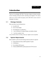
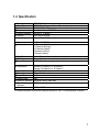
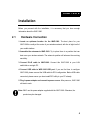
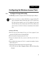
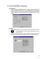
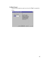
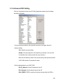
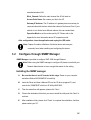
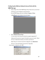
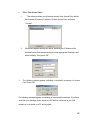
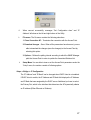
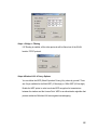
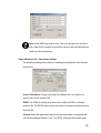
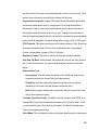
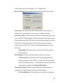
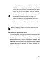
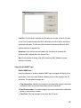
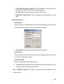
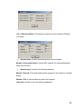
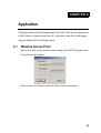
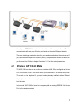
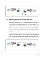
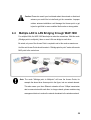
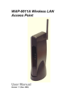
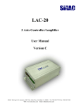
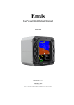
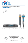
Wireless Access Point WAP-1960 User’s Manual Copyright Copyright 2002 by PLANET Technology Corp. All rights reserved. No part of this publication may be reproduced, transmitted, transcribed, stored in a retrieval system, or translated into any language or computer language, in any form or by any means, electronic, mechanical, magnetic, optical, chemical, manual or otherwise, without the prior written permission of PLANET. Planet makes no representations or warranties, either expressed or implied, with respect to the contents hereof and specifically disclaims any warranties, merchantability or fitness for any particular purpose. Any software described in this manual is sold or licensed "as is". Should the programs prove defective following their purchase, the buyer (and not Planet, its distributor, or its dealer) assumes the entire cost of all necessary servicing, repair, and any incidental or consequential damages resulting from any defect in the software. Further, Planet reserves the right to revise this publication and to make changes from time to time in the contents hereof without obligation to notify any person of such revision or changes. All brand and product names mentioned in this manual are trademarks and/or registered trademarks of their respective holders. Federal Communication Commission Interference Statement This equipment has been tested and found to comply with the limits for a Class B digital device, pursuant to Part 15 of FCC Rules. These limits are designed to provide reasonable protection against harmful interference in a residential installation. This equipment generates, uses, and can radiate radio frequency energy and, if not installed and used in accordance with the instructions, may cause harmful interference to radio communications. However, there is no guarantee that interference will not occur in a particular installation. If this equipment does cause harmful interference to radio or television reception, which can be determined by turning the equipment off and on, the user is encouraged to try to correct the interference by one or more of the following measures: 2 1. Reorient or relocate the receiving antenna. 2. Increase the separation between the equipment and receiver. 3. Connect the equipment into an outlet on a circuit different from that to which the receiver is connected. 4. Consult the dealer or an experienced radio/television technician for help. Notice 1: The changes or modifications not expressly approved by the party responsible for compliance could void the user's authority to operate the equipment. Notice 2: Shielded interface cables, if any, must be used in order to comply with the emission limits. 3 TABLE OF CONTENTS INTRODUCTION .......................................................................... 5 1.1 Package Contents ......................................................................................... 5 1.2 System Requirements ................................................................................... 5 1.3 Features ........................................................................................................ 6 1.4 Specification .................................................................................................. 7 INSTALLATION ........................................................................... 8 2.1 Hardware Connection.................................................................................... 8 CONFIGURING THE WIRELESS ACCESS POINT .............................. 9 3.1 Configure through DFU utility ........................................................................ 9 3.2 Configure through SNMP Manager............................................................. 14 APPLICATION ..........................................................................26 4.1 Wireless Access Point................................................................................. 26 4.2 Wireless AP Client Mode............................................................................. 27 4.3 LAN to LAN Bridging through WAP-1960 ................................................... 28 4.4 Multiple LAN to LAN Bridging through WAP-1960 ...................................... 29 TROUBLESHOOTING ..................................................................30 5.1 Frequently Asked Questions ....................................................................... 30 APPENDIX ................................................................................32 4 CHAPTER 1 Introduction Thank you for purchasing WAP-1960. This device features the latest innovation wireless technology making the wireless networking world happened. This manual guides you on how to install and properly use the WAP-1960 in order to take full advantage of its features. 1.1 Package Contents Make sure that you have the following items: • • • • • One WAP-1960 One AC Power Adapter One USB Cable (For Configuration) One CD-ROM with AP manager Software and Installation Manual One Quick Installation Guide If any of the above items are missing, contact your supplier as soon as possible. 1.2 System Requirements Before installation, please check the following requirements with your equipment. • • • • Pentium Based (And Above) IBM-Compatible PC System CD-ROM drive One Available USB Connector Windows 98/ME/2000/XP Operating System with TCP/IP protocol 5 1.3 Features Four operation modes selectable: AP / AP Client / Wireless bridge* Point to Point and Wireless bridge Point to Multipoint Highly Efficient Dipole Antennas Provide Extensive Range of Operation Auto Fall-Back Data Rate for Long-Distance Communication and Noisy Environments High-Speed Data Transmitter Rate Up to 11 Mbps Interoperable with IEEE 802.11b (DSSS) 2.4GHz-Compliant Equipment Features Roaming, Best Access Point Selection, Load Balancing, and Network Traffic Filtering 64-Bit and 128-Bit Wired Equivalent Privacy Support 63 clients to connect the network. (For best performance, the suggested maximum clients number of one WAP-1960 is 25.) Software Driver Upgrades * Terms “Wbridge” in the following sections 6 1.4 Specification • Standard • Signal Type • Modulation • Port • Ethernet Interface • Antenna • Data Encryption IEEE 802.11b DSSS (Direct Sequence Spread Spectrum) QPSK / BPSK / CCK One RJ-45 / One 10BASE-T IEEE802.3 10 BASE-T Dual Dipole Antenna 64 bit / 128 bit WEP encryption • Frequency • Channel 2.4GHz - 2.4835GHz 11 Channels (US, Canada) 13 Channels (Europe) 14 Channels (Japan) 4 channels (France) 2 channels (Spain) Up to 11Mbps(with automatic scale back) • Data Rate Power, Activity (wireless), Link (wired) • LED Indicators • Power Requirement 5V DC, 2A • Temperature Operating :0 degree C to 40 degree C, Storage: -20 degree C to 70 degree C, 90% Non-Condensing • Humidity 206 x 142 x 35mm • Dimensions 14dBm • Output Power 1dBi • Antenna Gain • Antenna Connector Reversed Polarity SMA Male ANT A* • Transmission Antenna ANT A, ANT B • Receive Antenna * For external antenna or directional antenna connection, ANT A is the dedicated connector. 7 CHAPTER 2 Installation Before you proceed with the installation, it is necessary that you have enough information about the WAP-1960. 2.1 Hardware Connection 1. Locate an optimum location for the WAP-1960. The best place for your WAP-1960 is usually at the center of your wireless network, with line of sight to all of your mobile stations. 2. Assemble the antennas to WAP-1960. Try to place them to a position that can best cover your wireless network. The antenna’s position will enhance the receiving sensitivity. 3. Connect RJ-45 cable to WAP-1960. Connect this WAP-1960 to your LAN switch/hub or a single PC. 4. Connect USB cable to WAP-1960 USB port. If you are first time to configure WAP-1960, please connect the USB cable for DFU configuration. Before USB cable connected, please ensure you have install DFU utility to your PC already. 5. Plug in power adapter and connect to power source. After power on, WAP-1960 will start to work. Note: ONLY use the power adapter supplied with the WAP-1960. Otherwise, the product may be damaged. 8 CHAPTER 3 Configuring the Wireless Access Point 3.1 Configure through DFU utility The DFU Utility is provided to configure the WAP-1960 setting through the USB port. Note: If this is your first time to configure WAP-1960, we suggest installing DFU utility for configuration. Before connect WAP-1960 to your PC, please ensure DFU utility had been installed to your OS. DFU installation will also install WAP-1960 USB driver. When Windows detect WAP-1960 from USB port and ask for the driver, click “Next” for Windows to automatically find the installed driver. Installing the DFU Utility A. Insert the Driver and Users Manual CD into your CD drive (suppose E:\) and execute the “DFU.EXE” which is in E:\Utility\WAP1960\. B. Then the wizard box will appears, please click “ Next “. C. Choose the destination folder that you want to install utility and click “Next” to continue. D. After installation finish, please click “Finish “ to complete the installation. And then please restart your PC. Configuring the Wireless Network Access Point with the DFU Utility Run the DFU utility form Start -> Programs ->Planet -> DFU, the following dialog will appear. 9 Note: If this is your first time to use the DFU utility to configure the Access Point, you can select “Access Point Wizard” as show above to set the basic settings of WAP-1960 (IP Address, SSID, Radio Channel). Or you may click the “Configuration” to get more advanced settings. But, please be sure that you have got enough information and authorization to set the advance setting. 10 3.1.1 Access Point Wizard configuration Set IP address Press the “Access Point Wizard” button, the following dialog box will show up. If there is a DHCP server in your LAN, you can “Enable” DHCP Client (Default is DHCP Client Enable). If no, please consult with your network administrator about how to configure WAP-1960 IP address. After complete this setting, click the “Next “. Set SSID Note: Please be sure the SSID of the Access Point and Wireless LAN card are the same. This defines those wireless devices to work in the same WLAN. SSID is the identification string for distinguish different wireless network. Key in any string you like to identify your wireless network. Click “Next “to continue. 11 Set Radio Channel Choose the radio channel you want to use, then click “Finish” to complete the setting. 12 3.1.2 Advanced DFU Setting Click the Configuration button from AP Utility Application window, then the dialog box below will appear. You may use those buttons in the right side as shown in the figure above for advance setting. Get: Show the current setting. Modify: Set new parameter to the identifier you selected. (You can click the identifier twice, which provides the same function) Set: Save and take any effect to the current setting. After press this button, WAP-1960 will take 20 seconds for restart. Set the settings below to your WAP-1960. Eth_IP_Address: Set an IP address for the AP. Eth_Submask: Set the subnet mask for the AP. Wirel_ESSID: ESSID is used by all wireless devices within the ESS or 13 extended wireless LAN. Wirel_Channel: Define the radio channel the AP will work on. Access Point Name: Set a name you like to the AP. Gateway IP Address: The IP address of a gateway device necessary for communication with devices outside the subnet of the Access Point. If your network is not divided onto different subnets, this can remain blank. Operation Mode to set the mode used by AP. Please refer to the Appendix for more information about AP’s operation mode. After configuration, close the application and unplug the USB cable. Note: Chapter 5 contains definitions of technical terms and acronyms commonly found when installing and configuring this device. 3.2 Configure through SNMP Manager SNMP Manager is provided to configure WAP-1960 through Ethernet. Note: Before using the SNMP manager to configure AP please consult with your Network Administrator to have enough information for the setting. Installing the SNMP manager A. Be sure that there is no AP inserted at this stage. Power on your computer and allow Window 98/2000/ME/XP to load fully. B. Insert the Driver and User’s Manual CD into the CD drive (suppose E:\) and execute the “SNMP.EXE” which is in E:\Utility\WAP1960\. C. Then the wizard box will appears, please click “Next “. D. Choose the destination folder that you want to install the utility and click “Next” to continue. E. After installation finish, please click “Finish“ to complete the installation. And then please restart your PC. 14 Configuring the Wireless Network Access Point with the SNMP Manager Before configure the AP with SNMP Manger Utility, Please ensure you had used DFU Utility to set an IP address for this Access Point. Run the SMNP Manager utility form the Start -> Programs ->Planet ->SnmpManger, then the dialog box below will appear. File -> Connect to Access Point – You can connect to the Access Point directly by typing the appropriate IP Address and Community in the panel,(The default community is” public”). Select the User or Administrator Authority in the Authority pull-down list. User: Allow you to view the Access Point Configuration only. Administrator: Allow you to view and change the Access Point Configuration. After the above configuration, press “OK”. 15 File -> Find Access Point– 1. This submenu allows you to find and connect to the Access Point without the necessity of knowing IP address. Click the Access Point and press “Connect”. 2. Window will appears a dialog box below, indicating the IP Address of the selected Access Point and prompting you enter appropriate Community and select Authority. Then press “OK”. 3. The following window appears indicating a successful connection to Access Point. Press “OK” The following message appears in indicating an unsuccessful connection. If you have seen this error message, please check your AP that has connected to your LAN properly or try to restart your PC and try again. 16 4. When connect successfully, messages “Get Configuration done” and “IP Address” will show on the left and right bottom of the Utility. File menu: The file menu contains the following selections. 1. Close Connection AP – Terminates the connection with the Access Point. 2. Download changes – Save. When all the parameters have been set, you are able to download the changes (save the changes) to the Access Point by selecting this option. 3. Options – Defines the polling interval according to which the SNMP Manager polls the Access Point in order to update the Associated Stations List. Setup Menu: You are able to view or set the Access Point parameters under the “Setup” menu, the section consists of following options. Setup -> Bridge -> IP Configuration The “IP Address” and “IP Mask” can be changed when DHCP client is not enabled. If DHCP client is enable, the IP Address and IP Mask field displays the IP Address and IP Mask that was assigned by the DHCP server. Additional you have to select the Primary Port, which is the interface that determines the AP dynamically obtains an IP address (Either Ethernet or Wireless). 17 Setup -> Bridge -> Filtering If IP Routing is enabled, all the other protocols will be filtered out of the WLAN besides TCP/IP protocol. Setup->Wireless LAN ->Privacy Options You can define the WEP (Wired Equivalent Privacy) Key values by yourself. There are 4 keys available for the 64bit WEP (10 Hex digit) or 128bit WEP (26 Hex digit). Enable the WEP option in order to activate WEP encryption for transmissions between the stations and the Access Point. WEP is an authentication algorithm that protects authorized Wireless LAN users against eavesdropping. 18 Note: All the WEP keys must be entry. Then you can select one of them to work. When WEP is enabled it must be the same on all the wireless devices (station and the access point). Setup->Wireless LAN -> Operational Settings The operational settings allow viewing or modifying the parameters of the Wireless Access Point. Access Point Name: Change the Access Point Name here, if you want to set another name to this Access Point. ESSID: The ESSID is used by all wireless devices within the ESS or extended wireless LAN. The ESSID value must be the same on all stations and Access points in this WLAN. Channel: Select the appropriate channel from the list provided to correspond with your network settings, between 1 and 13 (in ETSI). All devices that communicate 19 with this Access Point must use the same channel in order to work correctly. Verify that the correct channel is selected before clicking the Ok button. Fragmentation threshold: Fragment Threshold defines a threshold above which the wireless packet will be split up, or fragmented. For a fragmented packet, if transmission of part of it were to be interfered with, only the portion that was not successfully transmitted would need to be re-sent. Throughput will generally be lower for fragmented packets, since the fixed packet overhead consumes as higher portion of the RF bandwidth. Choose a setting within a range of 256 to 2346 bytes. RTS Threshold: This value should remain at its default setting of 2,346. Should you encounter inconsistent data flow, only minor modifications are recommended. Choose a setting within a range of 128 to 2,346 bytes Regulatory Domain: The value of this field is fixed and cannot be modified. Auto Rate Fall Back: When enabled, the transmission rate will set to the optimum rate. In case of interference, the system will automatically fall back to the lower speed. Authentication Type: Open System: With this setting, any station in the WLAN can receives and transmits data from the Access Point (null authentication). Shared Key: With this setting only stations using shared key encryption identified by the Access Point are allowed to associate with it. Both: with this setting, stations can communicate with the Access Point either with or without data encryption. Preamble Type (Short/Long):- Preamble is the first sub field of the PPDU, is an appropriable frame format for transmission between PHY (Physical layer). There are two preamble types, Short and Long Preamble. The Short Preamble option improves throughput performance Rate (Mbps): The unit adoptively selects the highest possible rate for transmission. 20 Select the basic rates for the following 1-2-5.5-11 (Mbps) option. Advanced Setting: There are three operational modes available for this setting. Access Point: This mode is set to WAP-1960 by default. This connects your wireless PCs to a wired network. In most cases, no change is necessary. Access Point Client: A WAP-1960 set to Access Point Client mode is able to talk to one main WAP-1960 functioning in AP mode and wireless client within its range. This mode allows your WAP-1960 client can then be wirelessly bridged to the main WAP-1960. A LAN attached to your WAP-1960 client can then be wirelessly bridged to the main WAP-1960. Enter the required MAC address of the main WAP-1960. Preferred BSS: Enter MAC address of the main WAP-1960 to wireless traffic to the device. Wireless Bridge: Two types of wireless bridge connections are allowed: A. Point to point: This mode connects two physically separated LAN segments by using two WAP-1960s. The remote WAP-1960 also needs to be set up as a Wireless Bridge. The designated access point with which it communicates is identified by the Remote MAC address. Remote MAC Address: Enabled only when Point-to-Point option selected. It corresponds to the MAC Address of the remote Wireless Bridge. B. Point to Multipoint: This mode allows you to construct a network that 21 have multiple WAP-1960s bridging multiple LANs wirelessly. Only central WAP-1960 is in Point to Multipoint mode. For all other bridged WAP-1960, configure them in Point to Point mode and enter the Remote MAC Address of central WAP-1960 set to Point to Multipoint. All the WAP-1960s must be configured on the same channel. Note: When WAP-1960 works in AP mode, it can have maximum 63 clients. For best performance, we suggest the maximum client number is 25. When WAP-1960 works in to Point-To-MultiPoint mode, you can have 5 remote sites to connect to this WAP-1960. The Transmission Antenna is ANT A, only use this side’s Reversed Polarity SMA Male connecter to connect external antenna. Caution: The Transmission Antenna is ANT A, only use this side’s Reversed Polarity SMA Male connecter to connect external antenna. Setup->Wireless LAN -> Authorized Mac Address For security purposes, the Access Point can discriminate its associations with other wireless stations. The Authorized MAC Address lets you select which stations are allowed throughput on the wireless interface. First you must enable the MAC address authorization table by placing a checkmark in the Authorized Table Enable. When you want to leave, please click Close to use the table. The table is maintained manually and can be updated and edited by downloading MAC addresses to the data table. 22 Load file: Click this button and enter the file name and location of the file you want to load. The file should contain the MAC addresses you wish to add to the table of authorized addresses. The file should be a simple text document with each MAC address written on a separate line. Download: Once the file has been loaded, click this button to download the Authorized MAC address file to the Access Point. Get: Click this button to obtain a list of the Authorized MAC Address currently entered on the table. Setup->Enable SNMP Traps Enable SNMP traps – Using this submenu to enable or disable SNMP traps, messages will display at the right bottom corner of the main window indicating that an action related to the AP took place. The permitted messages are: a. Trap association: Indicates the reception of an association request packet and the sender Station’s successful association with the Wireless AP. b.Trap Disassociation: This trap message is sent when disassociation notification packet is received from a station. c. Trap Reset: This trap message is sent when the AP resets. 23 d. Trap Setting IP Address with Ping: This trap message is sent when the AP IP address is sent with the transmission of a ping message. e. Trap Start UP: This trap message is sent when AP starts up. f. Trap Failed To Erase Flash: This trap message is sent when AP fails to erase flash. Setup->Authorization Authorization Using the submenu, the Administrator can change the passwords which referred to the community field for the User and the Administrator Authority. Commands menu: there are two options as described below: 1. Reset Device Select the option will reset the device and initiate any changes that have been made to the device configuration settings. 2. Restore Default Restore Access Point to factory default setting. Info menu: Various statistics concerning Ethernet and wireless operation of the Access Point can be viewed in this info menu. Info -> Wireless statistics: This dialog box reports the current statistics of the wireless activity. 24 Info -> Ethernet statistics: This dialog box reports the current statistics of Ethernet port activity. Network menu: Provides information about the current Network. Network ->Associated Stations: View the MAC Address of the Associated stations with the Access Point. Window menu: Consists of the following submenus Window ->Cascade: All opened windows will be arranged on the desktop in a cascade fashion. Window ->Tile: All open windows are visible on the desktop. Help menu: Provides on line help about the application. 25 CHAPTER 4 Application This chapter describe the four operating mode of your WAP-1960. The four working mode of WAP-1960 are, Wireless Access Point, AP’s Client Mode, wired LAN to LAN bridging mode and Multiple LAN to LAN bridging mode. 4.1 Wireless Access Point With the DFU utility, you will found the default setting of your WAP-1960 should runs in Access Point mode in default. With this mode, your Wireless network connection could act as following. 26 Any of your IEEE802.11b end nodes should found the nearest Access Point to communication with any other Wireless end-nodes or the wired Ethernet network. There are two things need to be check for your wireless end nodes, the services set ID (SID) and the Wired Equivalent Protocol (WEP), both parameters should the same with your Access Point. Refer to chapter 3, section 3.1.1 for the related parameters. 4.2 Wireless AP Client Mode The WAP-1960 can also act as a client on a wireless LAN. When configured as Access Point Client mode, WAP-1960 soon makes your connected PC a wireless end nodes. This mode can be deployed if your end nodes (already installed with an Ethernet Adapter) do not want to make any change but want to move it some where not easy to have the wire. In this mode, WAP-1960 will need to accompany with an existing IEEE802.11b Access Point in the wireless network. 27 4.3 LAN to LAN Bridging through WAP-1960 The LAN-to-LAN Bridge mode help to make the two Ethernet networks connected without any wire. With two WAP-1960s in this mode (Wbridge Point to Point), the two LANs in distance can communicate to each other. This could be deployed if the networks are hard to make the wire in between. Please be noted, please key in the MAC address to make the WAP-1960 communicate with a specific remote Access Point, you can find the MAC address either from the utility or from the label under the Access Point. In default, your wireless radio wave is transmitted through ANT A. (you can find the printing near the antenna connector). The omni antenna is with 14db transmitting power, if you would like to make longer distance that the default antenna cannot reach, consult your local dealer for more about how to extend your distance. 28 Caution: Please do consult your local dealer about the external or directional antenna you would like to install and get the connection. Improper outdoor antenna installation could damage the Access point or get injured or get killed in some condition like thunders or strong winds. 4.4 Multiple LAN to LAN Bridging through WAP-1960 For multiple LANs, the WAP-1960 also helps to make the connections. With this mode (Wbridge point to multipoint), three or more LANs can bridge to each other. Be noted, only one of the Access Point is required to set in this mode as master one. And the rest Access Points should remain in “Wbridge point to point” mode with remote MAC point to the central one. Note: The mode “Wbridge point to Multipoint” will turns the Access Points, for example the above three Access point in the figure, into one network domain. This also means your three Ethernet networks will use 11Mbps transmission rate to communicate with each other. In a large network, please consider using management device to reduce the network broadcast to the wireless network. 29 CHAPTER 5 Troubleshooting This chapter gives tips on how to configure the communication software. This chapter provides solutions to problems usually encountered during the installation and operation of the Wireless Network Access Point. Read the description below to solve your problems. 5.1 Frequently Asked Questions Can I run an application from a remote computer over the wireless network? This will depend on whether or not the application is designed to be used over a network. Consult the application’s user guide to determine if it supports operation over a network. Can, I play games with other members of the cordless network? Yes, as long as the game supports multiple plays over a LAN (local area network). Refer to the game’s user guide for more information. What is the IEEE 802.11b standard? The IEEE 802.11b Wireless LAN standards subcommittee, which is formulating a standard for the industry. The objective is to enable wireless LAN hardware from different manufactures to communicate. What IEEE 802.11 feature are supported? The product supports the following IEEE 802.11 functions: • CSMA/CA plus Acknowledge protocol 30 • Multi-Channel Roaming • Automatic Rate Selection • RTS/CTS feature • Fragmentation • Power Management What is Ad-hoc? An Ad-hoc integrated wireless LAN is a group of computers, each with a WLAN adapter, Connected as an independent wireless LAN. Ad hoc wireless LAN is applicable at a departmental scale for a branch or SOHO operation. What is Infrastructure? An integrated wireless and wired LAN is called an Infrastructure configuration. Infrastructure is applicable to enterprise scale for wireless access to central database, or wireless application for mobile workers. What is Roaming? Roaming is the ability of a portable computer user to communicate continuously while moving freely throughout an area greater than that covered by a single Wireless Network Access Point. Before using the roaming function, the workstation must make sure that it is the same channel number with the Wireless Network Access Point of dedicated coverage area. 31 CHAPTER 6 Appendix MAC Address A unique 48-bit, hard-coded Media Access Control address known by the station identifier. Ethernet IP Address The IP Address of the AP. Network-assigned Internet protocol address of the Access Point. Ethernet Subnet Mask The Ethernet station and the Access Point must be on the same subnet. The IP address for the Access Point must correspond to the Subnet Mask. Subnet Mask consists of four sets of three digits that divides a network into sub network. Wireless ESSID Select the ESSID to be used. The ESSID (up to 32 printable ASCII characters) of the unit is a string used to identify a WLAN. The ID prevents the unintentional merging of two co-located WLANs. ESSID Length The length of the ESSID (number of characters). Auto Rate Fall Back Select Enable or Disable. When this is enabled, the transmission rate is defined by the 32 past transmission status. Wireless Channel Select the channel to be used. The available channel number differ from country to country. There are up to14 channels available. WEP Key If the WEP option is enabled in order to activate WEP encryption for transmissions between the stations and the Access Point. WEP Type The Wired Equivalent Privacy Algorithm (64 or 128 bits) Wireless Fragmentation Threshold The size at which packets will be fragmented. Choose a setting within a range of 256 to 2346 bytes. This is the option for the Fragmentation Threshold activation. Wireless RTS Threshold Minimum packet size to require an RTS (Request To Send). For packets smaller than this threshold, an RTS is not sent and the packet is transmitted directly to the WLAN. This is the option for the RTS Threshold activation. WEP Keys#1-#4The default key that will be used. May be edited only if WEP type is 64 bits. Preamble Type Select Short or Long Preamble Type. Preamble is the first sub field of PPDU, which is the appropriate frame format for transmission to PHY (Physical layer).There are two options, 33 Short Preamble and Long Preamble. The Short Preamble option improves throughput performance. Authentication Type Select Open System or Shared Key Authentication Type Open System- With this setting, any station in the WLAN can associate with an Access Point and receive and transmit data (null authentication). Shared Key- With this setting, only stations using a shared key encryption identified by the Access Point are allowed to associate with it. Both- With this setting, stations communicate with or without data encryption. Operational Rate Set By default, the unit adaptively selects the highest possible rate for transmission. In case of obstacles or interference, the system will step down. Select the basic rates to be used among the following options 1 - 2 (Mpbs), 1 - 2 - 5.5 - 11 (Mbps). Select the Operational Rate set among the following options, 82 84 8B 96 (1 – 2 - 5.5 - 11 Mbps) or 82 84 0B 16 (1 - 2 Mbps). Beacon Period Set the Beacon Period parameter, which specifies the duration between the range 20-1000 with a typical value of 100. DTIM Set the DTIM period. Determines at which interval the AP will send its broadcast traffic. Default value is 4 beacons. Receive Antenna 34 Set the Receive Antenna among the following options Left(ANT B), Right(ANT A) or Diversity, to determine which antennas are used for reception. Transmit Antenna Set the Transmit Antenna to Right (ANT A). Only Antenna A can transfer data. Operational Mode Set one of the following operational modes on the Access Point Access Point Access Point Client Wireless Bridge Point-To-Point Wireless Bridge Point-To-MultiPoint User Community Indicates the user’s password. The default password is “public” User Access Indicates the user’s access rights. The user can only read and not set or change the AP’s parameters. Administrator Community Indicates the administrator’s password. The default password is “public”. Administrator Access Indicates the Administrator’s access rights. The administrator can read and also set or save changes to the AP’s parameters. 35 Manufacturer Community Indicates the manufacturer’s password. Manufacturer Access Indicates the manufacturer’s access rights. The manufacturer can read and set or save changes to the AP’s parameters. Also can view or modify the Hardware Configuration. Gateway IP Address Network Gateway IP Filtering Enable/Disable the possibility to allow only TCP/IP protocol packets to pass through the WLAN and any other protocol packets filtered out. DHCP client Enable/Disable automatic IP address assignment by the DHCP server Primary Port When DHCP enable, you have to select the Primary Port, which is the interface that determines the AP dynamically obtains an IP address (Either Ethernet or Wireless). Authorization Algorithm Enable/Disable the association with authorized MAC Addresses stations. SNMP traps Enabled/Disabled SNMP traps, which are the messages indicating the actions related to the AP that have taken place. 36 Preferred BSSID Remote MAC Address for connection, in Access Point Client or Wireless Bridge Operational modes. WEP 128 keys #1-#4 The default key that will be used. May be edited if WEP type is 128 bits. Auto Rate Fall Back: When this is enabled the transmission rate is the optimum rate. In case of obstacles or interference, the system will automatically fall back. Regulatory Domain: The value of this field is already set and cannot be modified. 37