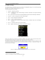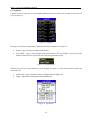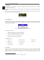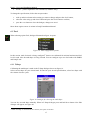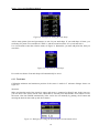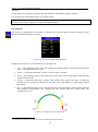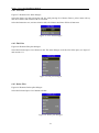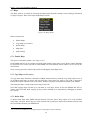
1
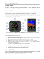
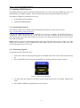
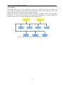
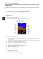
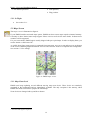
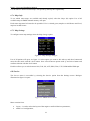
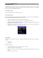
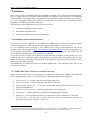
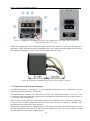
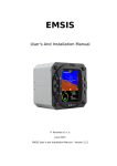
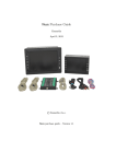
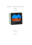
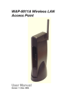
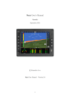
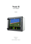
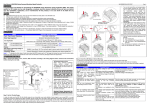
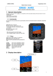
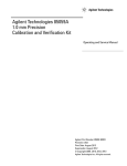
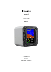
Emsis User's and Installation Manual Kanardia © Kanardia d. o. o. February 2014 Emsis User's and Installation Manual – Version 2.8 Contact Information Publisher and producer: Kanardia d.o.o. Ulica heroja Rojška 70 SI-3000 Celje Slovenia Tel: +386 40 360 512 Email: [email protected] A lot of useful and recent information can be also found on the Internet. See http://www.kanardia.eu for more details. Copyright This document is published under the Creative Commons, Attribution-ShareAlike 3.0 Unported license. Full license is available on http://creativecommons.org/licenses/by-sa/3.0/legalcode web page and a bit more human readable summary is given on http://creativecommons.org/licenses/by-sa/3.0/. In short, the license gives you right to copy, reproduce and modify this document if: you cite Kanardia d.o.o. as the author of the original work and you distribute the resulting work only under the same or similar license to this one. Credits Most of the figures were drawn using Open Office Draw and Inkscape applications. Photos and scanned material was processed using Gimp. All document sources are freely available on request under the license mentioned above and can be obtained by e-mail. Please send requests to [email protected]. Revision History The following table shows the revision history of this document. Revision Date Description Document File 1.0 Nov 2012 Initial release EmsisUserManual-100.pdf 2.0 Feb 2013 Added Installation EmsisUserManual-110.pdf 2.6 May 2013 Added Maps EmsisManual.pdf 2.8 Feb 2014 Added Logbook, Pilots, Map Settings, FW update EmsisManual.pdf Document can be downloaded from Kanardia web site http://www.kanardia.eu/downloads/emsis. 1 INTRODUCTION ....................................................................................................................................................4 2 EMSIS BASICS.........................................................................................................................................................5 2.1 Command Panel ................................................................................................................................................5 2.2 Turning ON/OFF.................................................................................................................................................5 2.3 Updating EMSIS Software ..................................................................................................................................6 2.3.1 Downloading Software ..................................................................................................................................... 6 2.3.2 Performing Upgrade ......................................................................................................................................... 6 3 GENERAL INFORMATION ABOUT EMSIS PFD .............................................................................................7 4 GENERAL INFORMATION ABOUT EMSIS EMS.............................................................................................8 4.1 Engine Sensors ..................................................................................................................................................8 4.2 CAN Bus .............................................................................................................................................................9 5 MAIN SCREEN ..................................................................................................................................................... 10 5.1 AHRS Screen ....................................................................................................................................................10 5.1.1 In Flight ........................................................................................................................................................... 11 5.2 Engine Monitoring Screen ...............................................................................................................................11 5.2.1 In Flight ........................................................................................................................................................... 12 5.3 Maps Screen ....................................................................................................................................................12 5.3.1 Maps Zoom Level ............................................................................................................................................ 12 6 EMSIS SETTINGS ................................................................................................................................................ 13 6.1 Logbook...........................................................................................................................................................14 6.2 Engine .............................................................................................................................................................15 6.2.1 Engine Type .................................................................................................................................................... 15 6.2.2 Sensors ........................................................................................................................................................... 15 6.3 Tank .................................................................................................................................................................17 6.3.1 T Shape ........................................................................................................................................................... 17 6.3.2 T min/max ...................................................................................................................................................... 18 6.4 Airspeed ..........................................................................................................................................................19 6.5 Units ................................................................................................................................................................20 6.6 Pilots ...............................................................................................................................................................20 6.6.1 New Pilot ........................................................................................................................................................ 21 6.6.2 Edit Pilot ......................................................................................................................................................... 21 6.6.3 Delete Pilot ..................................................................................................................................................... 21 6.7 Maps ...............................................................................................................................................................22 6.7.1 Enable Maps ................................................................................................................................................... 22 6.7.2 Copy Maps (or Licenses) ................................................................................................................................. 22 6.7.3 Delete Maps ................................................................................................................................................... 22 6.7.4 Maps Info ........................................................................................................................................................ 23 6.7.5 Map Settings ................................................................................................................................................... 23 6.8 Service .............................................................................................................................................................23 6.8.1 Layout ............................................................................................................................................................. 24 6.8.2 AHRS Level ...................................................................................................................................................... 24 6.8.3 Firmware update ............................................................................................................................................ 25 6.8.4 RamBoot update............................................................................................................................................. 25 6.8.5 Logger Settings ............................................................................................................................................... 25 6.8.6 Up/Down ........................................................................................................................................................ 25 6.9 About ..............................................................................................................................................................26 7 INSTALLATION ................................................................................................................................................... 27 7.1 Installation to the Instrument Panel ................................................................................................................27 7.1.1 EMSIS Back Panel Connectors and Cable Clearance ....................................................................................... 27 7.2 Connection to the Electrical System .................................................................................................................28 7.3 Pitostatic Connection.......................................................................................................................................29 7.4 Outside Air Temperature Probe Installation .....................................................................................................29 7.5 Connection to the CAN Network ......................................................................................................................30 7.6 Connection to the 485 Network .......................................................................................................................30 7.7 GPS Antenna Installation .................................................................................................................................30 Emsis – User’s and Installation Manual 1 Introduction First of all, we would like to thank you for purchasing our product. The EMSIS system is a set of complex electronics devices and we strongly recommend to carefully read this manual before installing and using EMSIS system. EMSIS is a name for a line of flight instruments which can be used as: primary flight display (PFD), engine monitoring system (EMS). The introduction chapter contains some general information about the instrument and its operation. Later chapters describe EMSIS use and reveal the details. 4 Emsis – User’s and Installation Manual 2 EMSIS Basics This chapter describes the organization of the EMSIS instrument. It teaches you about the individual buttons and their meaning. After reading it, you will be familiar with basic EMSIS operations. 2.1 Command Panel EMSIS instruments come in two physical sizes. The first one is a standard aviation size, which is 80 mm diagonal, while the second one is non-standard and is characterized with a 3.5" screen diameter. The EMSIS command panel is organized according to figure 1. It uses six (80 mm version) or five (3.5" screen version) small push buttons to manipulate the user interface. Additionally, it has micro SD card slot for software, maps and data updates. Figure 1: Organization of EMSIS front panel. EMSIS 80 mm version (left), EMSIS 3.5" screen version (right). Here is a brief description of individual items: 1. The up arrow button is used to move the menu selection, to change a value or a letter within active control or some other page special function. 2. The check button confirms selection and can be also viewed as an OK button. 3. The down arrow button does the same as the up arrow button, just in a reverse direction. 4. The power ON/OFF symbol button is normally not used. However on some EMSIS instruments, it is used to turn the instrument ON. Note that 3.5" screen EMSIS does not have a power ON/OFF button. 5. The cross button serves as the close command and can be also viewed as cancel button. 6. The page selector button is used to switch between pages (screens). 7. Micro SD card slot is used for software, maps and data updates. 2.2 Turning ON/OFF EMSIS is connected to the avionics power bus, therefore the instrument normally turns ON as soon as the avionics is switched ON and a couple of seconds later, it is ready for the operation. Some versions use power ON/OFF button to turn EMSIS ON. 5 Emsis – User’s and Installation Manual 2.3 Updating EMSIS Software The EMSIS software is under constant development and if you want to keep your EMSIS up to date, you should update your EMSIS regularly. This section describes actions required to update the software. The update for EMSIS is performed in two steps: downloading software updates, performing EMSIS upgrade. 2.3.1 Downloading Software The software updates can be found in the Downloads/Emsis/Software section of our web site; http://www.kanardia.eu/downloads/emsis. Click on the update file and save it to a hard drive of your PC computer. The update file name is “Update.kus”. Never change the name of the file. This file must be copied on micro SD card, more precisely into the base (root) folder of the card. Once file was copied, please make sure to safely remove micro SD card from PC. EMSIS software versions 2.4 and earlier support only micro SD cards with capacity 2 GB or less. The EMSIS unit is unable to recognize HDSD cards with a higher capacity. Please make sure that micro SD card is formatted as FAT 32 file system. 2.3.2 Performing Upgrade To upgrade correctly, follow this steps: 1. Insert micro SD card with program upgrade into EMSIS micro SD card slot with contacts facing up. 2. Press and hold the down button and turn EMSIS ON. Dialogue similar to figure 2 appears. Figure 2: Boot options dialogue. 3. Use the up and down button to select the Upgrade option and press the check button. Upgrade will begin. 4. Once finished, EMSIS programmed up to date will start. 6 Emsis – User’s and Installation Manual 3 General Information about EMSIS PFD EMSIS PFD consists of electronic units which work closely together to bring flight information onto graphical display. The system consists of the following electronic components: Airu (AHRS and GPS unit) – further on referred only as an AHRS unit – is an inertial navigation unit aided by the GPS and pressure sensors. AHRS provides attitude, position and velocities. AHRS unit is hidden inside EMSIS PFD unit. EMSIS PFD unit – presents all relevant information that appears on the CAN bus in a pilot friendly form on LCD screen. Most of this manual describes how to access, read and interact with the EMSIS display. EMSIS PFD unit uses state of the art MEMS1 sensors to read various physical quantities. Since all sensors are solid state, it has no moving parts. This means it has fewer problems with fatigue and ageing. The following MEMS sensors are used in the EMSIS PFD system: The angular rate sensors, also known as gyros, are used in the attitude calculation. The angular rates are integrated in time in order to predict new attitude from the old one. We could say that they give short-time attitude prediction. They are also used in gravity vector calculation. The acceleration sensors are measuring apparent gravity vector. The true gravity vector is calculated assuming coordinated flight and readings from the other sensors (velocity and angular rate sensors). The ball slip indicator is directly obtained from the acceleration sensors. The absolute pressure sensor is used to calculate altitude and vertical velocity (vario). The differential pressure sensor provides indicated airspeed (IAS). When it is coupled with the outside air temperature (OAT) sensor, it also calculates true air speed (TAS). Assuming coordinated flight, we calculate the referencing attitude from the gravity vector and heading. These values are then compared with the short-term prediction of the attitude. Non-linear Kalman filters are used to combine the short-term prediction and referencing attitude solution into one most probable solution. This is what you see on the attitude indicator. In a very similar way, short-term inertial position prediction is compared with the GPS position. Again, Kalman filtering is used to obtain the final solution. When engine monitoring unit (DAQU) is present on CAN bus, EMSIS PFD can also show relevant engine and fuel information. When maps are enabled and licensed, EMSIS PFD can also show raster maps on graphical display. Further chapters reveal the details. 1 MEMS - micro-electromechanical systems, a.k.a micro machines, a.k.a micro systems technology. 7 Emsis – User’s and Installation Manual 4 General Information about EMSIS EMS EMSIS EMS consists of electronic units which work closely together to bring engine and fuel information onto graphical display. The system is presented on figure 3. The system consists of the following electronic components: Engine monitoring unit (DAQU) is used to connect the engine, fuel and electric sensors. EMSIS EMS unit presents all relevant information that appears on the CAN bus in a pilot friendly form on LCD screen. Most of this manual describes how to access, read and interact with the EMSIS display. Figure 3: Illustration of EMSIS EMS configuration. When AHRS unit is present on CAN bus, EMSIS EMS can also show flight information on graphical display. When maps are enabled and licensed, and AHRS unit is present on CAN bus, EMSIS EMS can also show raster maps on graphical display. Further chapters reveal the details. 4.1 Engine Sensors Engine related sensors are connected to the engine monitoring unit (DAQU). DAQU unit is designed to be installed on the engine side of the firewall. This has two advantages: Since the unit is close to the engine all cables are short and no extensions are needed. This means less weight and makes installation simpler, too. We need only one tiny hole through the firewall for the CAN bus cable. The cable transfers all the information and provides the power supply for DAQU unit. DAQU unit is designed to monitor engine sensors for various engines such as Rotax, Jabiru, Lycoming, etc. When an engine is equipped with proper sensors, it can measure engine RPM, cylinder head temperature (CHT), exhaust gas temperature (EGT), oil pressure, oil temperature, fuel pressure, fuel flow, fuel level, manifold pressure, carburetor air temperature, voltage, battery current, alternator current, coolant temperature and more. In the case of gyrocopter or helicopter installation, it also reads the rotor RPM sensor. The results of all these measurements are then transmitted on the CAN bus, where all other units are able to read them. More about DAQU unit and engine sensors is written in DAQU Installation Manual. 8 Emsis – User’s and Installation Manual 4.2 CAN Bus The EMSIS system can be easily extended into a much more complex form, shown on figure 4. We achieved this by introducing CAN bus for the communication between the units. The CAN bus does the magic of the all possible known and unknown future extensions. Imagine the CAN bus as a kind of computer network. Just like new computers can be easily connected to the network, we connect all new devices to CAN. This allows introduction of secondary EMSIS unit, autopilot, weather service, external warning panel lights, transponder, etc. Figure 4: Illustration of EMSIS configuration using CAN bus. 9 Emsis – User’s and Installation Manual 5 Main Screen The EMSIS unit can toggle between three (or more) different main screens depending on your EMSIS type. Most common are: AHRS screen – with artificial horizon with flight information, Engine monitoring screen – with relevant engine and fuel information, Maps screen – with graphical display of raster maps. 5.1 AHRS Screen The AHRS screen is illustrated on figure 5. It is an artificial horizon with the flight information displayed on the screen. Figure 5: EMSIS AHRS screen. The screen consists of the following items: 1. Quality of the GPS fix. Three green bars mean 3D fix, two yellow bars are 2D fix and cross means no signal from GPS. 2. The turning rate scale. Inner points indicate one minute turn (6 degrees per second) while outer points indicate 30 seconds turn (12 degrees per second). 3. GPS track – active only when ground speed is over 20 km/h. 4. The vertical speed indicator (vario) scale. 5. The vario label displays current value of the vertical speed. 6. The baro corrected altitude value. 7. Current QNH setting (baro-correction). 8. Indicated airspeed (IAS). 9. Outside air temperature (OAT). 10. The inclinometer (slip-skid) indicator. 11. Artificial horizon with roll and pitch indications. 10 Emsis – User’s and Installation Manual 5.1.1 In Flight While in flight, two options can be set: push and hold up button sets current pitch, see figure 6, Figure 6: Setting pitch. up and down button sets brightness or QNH, depending of settings, see section 6.6.4. 5.2 Engine Monitoring Screen The engine monitoring screen is illustrated on figure 7. It can be designed differently for each EMSIS unit regarding to the wishes of the pilot. Figure 7: EMSIS engine monitoring screen. The screen consists of the following items: Screen can optionally also show: 1. Engine RPM indicator. CHTs, 2. Manifold pressure indicator. EGTs, 3. Fuel level indicator (up to two tanks). Rotor RPM, 4. Fuel consumption info. Fuel flow, 5. Engine time. Pneumatic pressure, 6. Alternator current. Airspeed (IAS and/or TAS), 7. System voltage. Altitude, 8. Oil and water (coolant) temperatures. Vario, 11 Emsis – User’s and Installation Manual Trim position, 9. Oil and fuel pressures. Flap position. 5.2.1 In Flight See section 5.1.1. 5.3 Maps Screen The maps screen is illustrated on figure 8. If your EMSIS unit has activated maps option, EMSIS can show raster maps copied to internal memory. Currently we have limited raster maps support. Please visit our web site for more details. In future more countries will be supported. For your convenience EMSIS unit is usually shipped with pre-copied maps. In order to display them, you need to obtain a valid license file2. As visible from figure, maps screen is composed from raster map, one row on top and two rows on bottom of the screen containing flight information. All rows and each box inside it are optional and configurable. See section 6.7.5 for settings. Figure 8: EMSIS maps screen. 5.3.1 Maps Zoom Level EMSIS unit keeps updating several different moving map zoom levels. These levels are seamlessly computed in the background and are immediately available. The only exception is the start-up, when EMSIS unit needs some time to prepare the initial maps. Zoom levels are changed with up and down button. 2 An active GPS signal is required. 12 Emsis – User’s and Installation Manual 6 EMSIS Settings The EMSIS Settings screen allows you to set several user configurable settings. It is accessed by pressing the page selector button. Figure 9 illustrates the screen. The following options are available: Logbook – displays the pilot log. Engine – configures the engine related settings and sensors connected to the engine monitoring unit (DAQU)3. Tank – opens menu for the fuel level measuring hardware and for the fuel tank shape calibration3. Airspeed – is used to configure the aircraft airspeed ranges4. Units – is used to change the instrument units. Pilots – is used to manipulate with pilots. Maps – is used to copy and delete maps and maps licenses, configure maps screen and display maps info. Service – is a gateway to the service specific settings. About – displays information about software and hardware version. Figure 9: EMSIS settings screen. Some user options are not shown on secondary EMSIS, some options require password entry before proceeding and some options are available only when correct hardware is detected. The factory password is 314, first three most significant digits of number π as seen on figure 10. The password was introduced in order to prevent unwanted accidental alterations of important settings. The password cannot be changed. Figure 10: EMSIS password is required in order to access certain options. 3 Engine monitoring unit (DAQU) is required. 4 Option is not available for aircrafts with predetermined ranges. 13 Emsis – User’s and Installation Manual 6.1 Logbook Logbook serves as a pilot log. It records flights and displays them on the list. An example of such record is given on figure 11. Figure 11: Logbook. Pressing check button in Logbook list, opens the following commands, see figure 12: Details – opens log entry and displays the details. Copy flight – copies selected flight to the inserted micro SD card. Flight is saved in kml file format (*.kml) and can be opened on a PC with Google Earth program. Figure 12: Logbook menu. Each log entry reveals several details of a selected flight, see figure 13. These entries in the log have the following rows: General info – date, pilot name, number of flights and total flight time. Flight – takeoff time, landing time and flight duration. Figure 13: Log details. 14 Emsis – User’s and Installation Manual 6.2 Engine The Engine menu is accessible by selecting the Engine option from the Settings screen. Dialogue illustrated on figure 14 opens. In menu, you can set the engine type and configure sensor parameters for the engine monitoring unit (DAQU)5. With up and down button select the option you want to configure and push the check button to access the menu. The cross button closes the Engine menu. Figure 14: Engine menu. 6.2.1 Engine Type Depending on specifications of your aircraft, select the correct engine. Figure 15 shows the engine selection dialogue. Setting the engine type allows EMSIS unit to calculate fuel consumption and has no other effect on the instrument. Figure 15: Dialogue for setting the engine type. When dialogue is opened: push the check button to start selecting an engine, with up and down button select the correct engine, push the check button to confirm the decision, push the cross button to exit the dialogue. Available engines are: Generic Rotax 912 100 Jabiru 2200 Rotax 582 65 Rotax 912 100A Jabiru 3300 Rotax 912 80 Rotax 912 iS Rotax 912 80A Rotax 914 6.2.2 Sensors DAQU is able to read many different sensors and these sensors can be connected to different DAQU channels. Using the table illustrated on figure 16 we tell DAQU which sensor is connected to which channel and what is the role of that sensor. Additionally, some other configuration parameters can be also set. 5 When no DAQU is connected to the CAN bus, this option is obsolete. 15 Emsis – User’s and Installation Manual Figure 16: List of sensors connected to DAQU unit. Each row in the table corresponds to one DAQU channel. Channels are labeled as combination of one capital letter and one number. Letter defines the channel type, while the number enumerates channels of each type. Four channel types are used in DAQU: A: analog channels with –2.5 V to +2.5 V input, which are typically used to connect resistive sensors and thermocouples. B: analog channels with 0 to +5 V input, used to read active sensors. Active sensors require power in order to operate properly. C: analog channel with 0 to +30 V input, used to read higher voltage levels. Z: digital channels, used to measure time between pulses. See DAQU Installation Manual for more details. After sensors are connected to the DAQU unit, each sensor needs to be configured. Select the appropriable channel from the list by using up and down button and confirm selection by pushing the check button. Dialogue illustrated on figure 17 opens. Figure 17: Dialogue for setting a sensor on DAQU channel. Dialogue consists of: Function – what is sensor used for. Depending of the channel type, different functions are available. Sensor – type or model of sensor installed. Isolated – if sensor is isolated or not (only for CHTs and EGTs). Filter time constant – how quickly DAQU unit reacts to a sensor change. Large value means slower reactions. 16 Emsis – User’s and Installation Manual Divider – pulses required for one event/turn (Z channels only). To change the specifications, follow the next procedure: 1. with up and down button select setting you want to change and press the check button, 2. select the value using up and down button and press the check button to confirm, 3. press the cross button to close the dialogue, changes are saved. More about engine sensors is written in DAQU Installation Manual. 6.3 Tank When selecting option Tank, dialogue illustrated on figure 18 opens. Figure 18: Tank configuration options. In this section, tank of aircraft is being configured6. Sensors are calibrated for minimal and maximal fuel level in tank. Also the tank shape is being selected. You can configure up to two fuel tanks with EMSIS and DAQU unit. 6.3.1 T Shape Calibrating the tank shape is made in the T Shape dialogue shown on figure 19. Select correct shape for your aircraft tank. If none fits your aircraft specifications, select box shape with the volume closest to yours. Figure 19: Dialogue for selecting the tank shape. You can also set tank shape manually. When in T Shape dialogue press and hold down button. New Edit dialogue will appear, see figure 20. 6 When no DAQU is connected to the CAN bus, this option is obsolete. 17 Emsis – User’s and Installation Manual Figure 20: Dialogue for editing the tank shape. Add as many points (liters and percentages) as suit for your tank shape. If your tank shape is linear, you need only two points. First would be 0 l and 0 %, and the second would be size of tank and 100 %. Use check button to enter the selection menu, see figure 21. Remember, you must add point first, then you can edit it. Figure 21: Edit point for tank shape. Exit with cross button. Your tank shape will automatically be saved. 6.3.2 T min/max Calibrating minimum and maximum position of the sensor is made in T min/max dialogue shown on figure 22. Minimum: Make sure that the tank of the aircraft is empty and sensor is connected to DAQU unit. In the Sens row you can observe the sensor current value. When Min is selected press and hold the check button to write the sensor value into EMSIS automatically. Value can be also set manually by pushing check button and entering the desired value with up and down buttons. Figure 22: Dialogue for setting the tank minimum and maximum values. 18 Emsis – User’s and Installation Manual Maximum: Do the same as for minimum, but make sure that the tank is full and Max option is selected. Cross button closes the dialogue and saves inserted values. Note that it is not possible to exit without saving new values into DAQU unit. If you do not want to save new values, the only possibility is to switch the EMSIS unit OFF. 6.4 Airspeed The Airspeed configuration is accessible by selecting the Airspeed option7 from the Settings screen. Dialogue illustrated on figure 23 opens. Figure 23: Airspeed configuration dialogue. Change can be done for five scale limits as seen on figure 24: 1. Low – is the beginning of the scale. The scale shows nothing until the aircraft exceeds this speed limit – only numerical value is seen. 2. Yellow1 – to this limit the range is yellow. Yellow1 range is optional. 3. Green – the maximum value for the green range. Green range is the normal range of the operating speeds for the aircraft. 4. Yellow2 – to this limit the range is yellow. The second yellow range is the range, in which the aircraft may be operated in smooth air, and then only with caution to avoid abrupt control movement. 5. Red – to this limit the range is red – also the end of the scale. Beginning of the red range indicates the maximum demonstrated safe airspeed that the aircraft must not exceed under any circumstances (VNE). Figure 24: Example of an airspeed scale. 7 Not available for all layouts. Some layouts have predetermined speed ranges. 19 Emsis – User’s and Installation Manual 6.5 Units Units configuration is accessible by selecting the Units option from the Settings screen. Dialogue illustrated on figure 25 opens. Figure 25: List of configurable units in EMSIS unit. EMSIS uses several units for different physical quantities like distance, velocity, mass, volume, etc. Table 1 shows available units. Physical quantity Available Units Latitude/longitude D°MM’SS’’, D°MM.MM’ Heading True, Magnetic UTC difference ± hour(s) Distance (length) nm, sm, km Speed (velocity) km/h, kts, mph Vario (vertical velocity) m/s, ft/min, kts Wind m/s, km/h, kts, mph Altitude (length) meter, feet QNH (pressure) hPa, inHg Mass kg, lbs. Temperature C, F Pressure (used in engine) bar, psi Volume l, US gal Flow l/h, gal/h Table 1: Available units for individual physical quantity. 6.6 Pilots Pilots menu allows to add, edit or delete pilots. Dialogue is illustrated on figure 26. Figure 26: Pilots configuration options. 20 Emsis – User’s and Installation Manual 6.6.1 New Pilot Figure 27 illustrates New Pilot dialogue. Select the Name row and activate the edit box with pressing check button. Enter a pilot’s name with up and down buttons and confirm with check button. Select the Instructor row, activate selection with check button and chose if Pilot is Instructor. Figure 27: New Pilot dialogue. 6.6.2 Edit Pilot Figure 28 illustrates Edit pilot dialogue. Select the Pilot and press check button to edit. The same dialogue as for the New Pilot opens, see figure 27 and section 6.6.1. Figure 28: Edit pilot dialogue. 6.6.3 Delete Pilot Figure 29 illustrates Delete pilot dialogue. Select the Pilot and press check button to delete. Figure 29: Delete pilot dialogue. 21 Emsis – User’s and Installation Manual 6.7 Maps The Maps menu is accessible by selecting the Maps option from the Settings screen. Dialogue illustrated on figure 30 opens. Here raster maps manipulation is done. Figure 30: Maps menu. Menu consists from: Enable Maps, Copy Maps (or licenses), Delete Maps, Maps Info, Map Settings. 6.7.1 Enable Maps This option is needed to enable raster maps screen. Each EMSIS unit has its own unique password which enables raster maps screen. Please contact Kanardia for password. You need to provide us with EMSIS unit serial number. Serial number can be seen in the About menu. Once correct password is entered, this option will disappear from Maps menu. 6.7.2 Copy Maps (or Licenses) To copy raster maps from micro SD card to EMSIS internal memory select the Copy Maps option. List of all available raster maps on micro SD card will open. Select map you want to copy with up and down button and confirm selection with check button. Wait for copying to be finished and restart your EMSIS. The same procedure is used for the raster maps license file. Note that copying maps can take up to one hour or even more. Please do not turn EMSIS unit OFF or remove micro SD card while copying. It may result in EMSIS to be inoperable by damaging its internal file system8. 6.7.3 Delete Maps To delete raster maps from EMSIS internal memory select the Delete Maps option. List of all available raster maps will open. Select map you want to delete with up and down button and confirm selection with the check button. Restart your EMSIS unit. 8 For convenience, EMSIS unit is shipped with pre-coped maps to internal memory. 22 Emsis – User’s and Installation Manual It is advisable to delete obsolete maps. This speeds up start-up time significantly. 6.7.4 Maps Info To see which raster maps are available and already copied, select the Maps Info option. List of all available maps in EMSIS internal memory will open. Each raster map must be licensed to be operable. If Lic is colored green, map has a valid license and if red, map has invalid license. 6.7.5 Map Settings To configure raster map settings select the Map Settings option. Figure 31: Map Settings dialogue. List of all options will open, see figure 31. Select option you want to edit with up and down button and enter the edit mode with the check button. Now select between options with up and down button and confirm selection with the check button Each box allows you to select between IAS, TAS, GS, ALT, HDG, Time, UTC, RPM and ROTOR rpm. 6.8 Service The Service menu is accessible by selecting the Service option from the Settings screen. Dialogue illustrated on figure 32 opens. Figure 32: EMSIS Service menu. Menu consists from: Layout – is used to select the layout of the engine or artificial horizon parameters, AHRS level configuration, 23 Emsis – User’s and Installation Manual Firmware update, RamBoot update, Logger settings, Up/down button configuration. 6.8.1 Layout The Layout setting is accessible by selecting the Layout option from the Service screen. In most cases the correct layout is set in the factory and you do not need to change it unless we advise you to do so. If not, depending on specifications of the aircraft, select the correct layout for your EMSIS instrument. Figure 33 shows a dialogue for selecting the correct layout. Figure 33: Dialogue for setting EMSIS layout. When dialogue is opened: push the check button to start selecting the layout, with up and down button select the correct layout and confirm with check button, push the cross button to save and exit the dialogue. EMSIS will restart. 6.8.2 AHRS Level During the assembly of the AHRS unit into the EMSIS unit and during the installation of the EMSIS unit into the instrument panel, a small misalignment may appear. This means that internal axes of the AHRS unit are not parallel to the airplane axes – the AHRS unit is slightly rotated. Such misalignment can be perfectly adjusted without loss of precision using the procedure described next. Please make sure that airplane is level for both, roll and pitch. Make also sure that EMSIS unit is turned ON for at least five minutes – this warms up the internal electronics and stabilizes numerical filters. Once the airplane is level and steady, select the AHRS level option to start the automatic calibration procedure. Window illustrated on figure 34 opens. Figure 34: Calibrating the AHRS level. Wait for the progress bar to finish and observe the roll and pitch numerical values. At the end they should be close to zero. 24 Emsis – User’s and Installation Manual 6.8.3 Firmware update This function allows to update firmware of units connected to your EMSIS. This units can be AIRU (artificial horizon unit), DAQU (engine monitoring unit) or MAGU (magnetic compass). It is advisable to use this function when updating EMSIS software. 6.8.4 RamBoot update Do not use this function unless we advise you to do so. 6.8.5 Logger Settings This function can help you adjust logger sensitivity. Basically this means you can set low/high border for logger to start/stop logging data to internal memory. You can set: Takeoff – when plane reaches this speed, takeoff will be detected. Landing – when plane’s speed will go below this value, landing will be detected. Rotor RPM – when rpms rise above this value, rotor ignition is detected, and when rpms descend bellow this value, rotor shutdown is detected. Engine RPM – when rpms rise above this value, ignition for engine is detected, and when rpms descend bellow this value, engine shutdown is detected. Figure 35: Logger Settings. 6.8.6 Up/Down The function of up and down button can be configured. Referring to the pilot wishes, two options are available: set brightness, set QNH. Procedure for changing: 1. from the Service menu, select the Up/Down option, see figure 32, 2. push the check button to activate selection, 3. with up and down button select the desired option (brightness/QNH) and confirm it with check button, 4. exit and save with cross button. 25 Emsis – User’s and Installation Manual 6.9 About The About is accessible by selecting the About option from the Settings screen. New window illustrated on figure 36 opens with information about: program version, program date, bootloader version, serial number, hobbs time, credits. Figure 36: About. 26 Emsis – User’s and Installation Manual 7 Installation This section provides information about the installation of EMSIS unit to the aircraft instrument panel. Here we assume that you are familiar with the EMSIS user interface system. Therefore we recommend reading EMSIS User’s Manual from the beginning before proceeding with the installation. As a customer you are not obligated to follow these steps but it is really wise to use some tips we learned after many installations of EMSIS systems done in the past. The following system components are covered in next sections: installation of EMSIS unit (all versions), GPS antenna installation and Outside air temperature (OAT) sensor installation. 7.1 Installation to the Instrument Panel This section covers the installation of the EMSIS unit. EMSIS 80 mm version is presented (standard avionics unit dimension), while the same principles apply for the EMSIS 3.5” screen version. Cut your instrument panel according to your EMSIS version using cut-out dimensions and cut-out template given in the Appendix or http://www.kanardia.eu/downloads/emsis. Print the corresponding page on a hard paper. After printing take precise ruler or measuring tape and make sure that printed sizes are correct. Drill the mounting holes in the panel using 4.5 mm drill. If you do not want to cut the panel yourself, you may consider to machine cut the opening in a local workshop using CNC equipment (a laser cutting machine is typically used). After cutting make sure, that EMSIS fits into the new opening. You can powder paint the panel using non-reflective dark paint. This makes excellent results in practice. The EMSIS unit is mounted from the back. Position EMSIS unit in the instrument panel and use the screws to fix it in place. 7.1.1 EMSIS Back Panel Connectors and Cable Clearance EMSIS units are divided into two main groups (according to the back panel), EMSIS with AHRS unit built-in and all the others. Here is a brief description of individual connectors from figure 37: 1. Total pressure port – must be connected to the total pressure tube. 2. Static pressure port – must be connected to the static pressure tube. 3. Standard GPS antenna port – is used for external GPS antenna needed by the GPS receiver integrated on AHRS unit. 4. Outside air temperature port – connects to the Kanardia OAT digital probe. 5. Encoder port – connects with external encoder for regulating QNH (optional). 6. RS-485 port – used to connect with devices via 485 protocol such as indicators or LX Cluster. 7. Two CAN ports9 – they are used to connect other CAN devices. Connectors are equivalent so either one can be used to connect a CAN device. 9 EMSIS PFD is shipped with a connector inserted into one CAN port. It is a 120 Ω network terminator resistor to start and terminate the network. When DAQU unit is connected, terminator can be disconnected. 27 Emsis – User’s and Installation Manual Figure 37: EMSIS unit with AHRS unit built-in (left), EMSIS slave unit (right). Both versions are available, 80 mm and 3.5" screen. EMSIS unit requires about 6 cm additional clearance behind. This clearance is needed for the connectors and cables. Figure 38 shows the photo of EMSIS 80 mm version taken from side together with all cables and connectors. EMSIS 3.5" screen version requires similar clearance space. Figure 38: Side photo of EMSIS 80 mm version with all cables connected. 7.2 Connection to the Electrical System The EMSIS unit must be connected to a 12 V DC standard aircraft power source. Additionally it can be connected to the backup battery – UPSU unit. The EMSIS display consumes very little power (less than 2 W), which means about 0.15 A at 12 V. We recommend connecting EMSIS using appropriately rated breaker or replaceable fuse on the power input. A 1 – 2.5 ampere fuse is appropriate. Make sure that all units share the same common ground. There should be none or minimal voltage (up to 10 mA) between common ground and each unit ground, when all units are turned on. Otherwise your aircraft electrical system needs a good inspection. EMSIS with AHRS unit built-in is shipped with 1 m long power cable with 2 pin female connector on one side and unterminated solid lines on the other. Red line connects to the 12 V DC avionics power bus and blue line connects to the aircraft common ground. 28 Emsis – User’s and Installation Manual If you find power cable too long, you can shorten it to any length, saving some precious weight. When you use more than one EMSIS unit in the cockpit, other EMSIS units get power via CAN cable. In Appendix at the back of this document you will find connection schema for EMSIS unit with or without UPSU unit. 7.3 Pitostatic Connection In most avionics installations there are several instruments that need to be connected to the pitostatic system. A typical instrument panel has at least a mechanical airspeed indicator and altimeter. EMSIS PFD unit shares the same pitostatic source with them. Pitostatic consists of static pressure tubing and total pressure tubing. In order to connect to the static source, cut the static tube on an appropriate place and insert plastic T junction. Cut some new tube to length and connect T junction with the EMSIS PFD static port. We recommend use of hose clamps on all junctions and connections to secure against slippage and to reduce chance of static pressure leak. Use the procedure above for the total pressure tube as well: cut the total pressure tube, insert T junction, connect T junction and EMSIS total port and secure connections using hose clamps. We strongly recommend labeling each tube before connecting to the EMSIS PFD or any other instrument. If you ever have to remove EMSIS PFD from the instrument panel, this will help a lot when you will reinstall it. 7.4 Outside Air Temperature Probe Installation Although the OAT probe is a simple element in the EMSIS PFD system, its installation requires some attention. Outside air temperature (OAT) probe is shipped with the EMSIS PFD unit. This is a digital temperature sensor inserted into a threaded aluminium tube. The default OAT cable length is 1.5 meters but other lengths are available on request. OAT information is required to calculate the true airspeed from the indicated airspeed and altitude, as well as to provide you with the outside temperature information. In order to provide accurate measurements, the OAT probe must be installed on a proper place where the probe is not exposed to the disturbing sources of heat: engine heat and exhaust heat, direct sunlight, heated air exited from cabin. We also do not recommend installing the probe in the cabin area, since the elevated temperature in the cabin may influence the back side of the probe, though such influence is usually small. Please follow these steps to install the OAT probe: 1. Locate a spot in the aircraft taking into account the considerations from above and drill a ϕ 8 mm hole. 2. Remove the external nut from the probe but keep the washer, internal nut and plastic insulation tube on the probe. 3. Install the probe into the hole from the interior. Guide the cable trough the aircraft to the EMSIS PFD back panel. 29 Emsis – User’s and Installation Manual 4. Apply some lock-tight and thread the external nut to the probe. The avoid losing the cap due to vibrations. lock-tight is necessary to 5. Tighten the internal nut so that the probe sits firmly and apply lock-tight on the nut. Do not over tight it. 6. Slide the plastic insulation tube over the exposed threads of the probe and cover as much threads as possible. Shrink the tube using hot air blower. Do not use open flame. Plastic insulation (shrink) tube also serves as internal isolation. Figure 39: Inserting the OAT probe (left), cap is in place, tighten the internal nut, slide the insulation tube (right). 7.5 Connection to the CAN Network Both CAN ports at the back of the EMSIS unit are equivalent. In most standard configurations with EMSIS EMS, one CAN port is used to connect with DAQU (engine monitoring unit), while the other is unused or connected to other EMSIS unit. In standard configurations with EMSIS PFD, one CAN port is connected to terminator, while the other is unused or connected to other EMSIS unit. One CAN port may be used to connect with DAQU (engine monitoring unit), in this case terminator can be disconnected. Just to remind you, DAQU unit has a 120 Ω CAN network terminator resistor built-in to start and terminate the network. 7.6 Connection to the 485 Network The RS-485 connector is used to connect with devices via 485 protocol. Most common devices to connect with EMSIS are various (57 mm, 80 mm …) indicators and LX Cluster. 7.7 GPS Antenna Installation Please, consider mounting the GPS antenna using the following recommendations: Find a good spot in a cabin where the antenna is able to “see” blue sky during most of the aircraft movement. Such a good spot can be usually found on the top of the instrument panel cover, just below the canopy. Mounting surface should be flat, clean and rigid. Avoid close proximity to any transmitting antennas like radio stations, transponders or any other active GPS antennas (GPS antennas may interfere each other). Antenna must not be covered or obstructed by metals (metals sheets, conductive material (like carbon fibers). rods) or any other The supplied antenna length is 1.2 meter, but other lengths are available on request. The triangle/GPS text must point upwards – to the sky. For the installation use self-adhesive tape and fix the antenna on a rigid and clean surface. 30 Emsis – User’s and Installation Manual The supplied antenna is not intended to be installed on the aircraft exterior. If you need to install the antenna on the external surface, search a suitable antenna in your local avionics shop. Any 3.3 V active antenna with SMA male connector can be used. The AHRS unit, which is hosted by the EMSIS PFD unit, has an internal super capacitor which provides power for the GPS for about 14 days after the last flight. It enables so called hot-start of the GPS module. A hot-start means that GPS constellation almanac is kept in the GPS module memory after the EMSIS unit was powered OFF. Note: On a first start up, on a cold-start or when EMSIS PFD is moved for a significant distance without receiving GPS signal (shipping across the Globe), GPS receiver needs to download almanac from the constellation. This requires a good GPS signal and may take a few minutes. 31