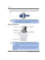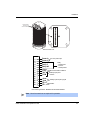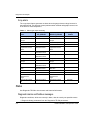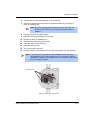
1
Operating Instructions DSGD® Radiation-Based Detector with GEN2000® Electronics for Foundation Fieldbus® Applications Measuring Density Document ID: 31628 Nuclear Revision history Version Description Date 1.0 Initial release. Formerly 245959-EN. Changed CD art number 32700, Corrected copyright and registered marks Electronics revision Added certification information and IECex label Changed company name, logo, and website 051201 1.1 1.2 1.3 1.4 061208 090306 090814 110301 Copyright© 2011 VEGA Americas, Inc., Cincinnati, Ohio. All rights reserved. This document contains proprietary information of VEGA Americas, Inc. It shall not be reproduced in whole or in part, in any form, without the expressed written permission of VEGA Americas, Inc. The material in this document is provided for informational purposes and is subject to change without notice. GEN2000® is a registered trademark of the VEGA Americas, Inc.. HART® is a registered trademark of The HART© Communication Foundation. FOUNDATION Fieldbus is a trademark of the Fieldbus Foundation. NI-FBUS Configurator is a registered trademark of National Instruments® . ISO 9001 approval by Lloyd's Register Quality Assurance Limited, to the following Quality Management System Standards: ISO 9001:2000, ANSI/ASQC Q9001-2000, Approval Certificate No. 107563. VEGA Americas, Inc. 4170 Rosslyn Drive Cincinnati, Ohio 45209-1599 USA Tel: +1 513-272-0131 Fax: +1 513-272-0133 Website: www.vega-americas.com Warning: To ensure CE compliance, use this equipment only in the manner that this manual describes, per VEGA specifications. Otherwise, damage to the unit or personal injury may result. NOTES DSGD Installation and Operation Guide Table of Contents Revision history . . . . . . . . . . . . . . . . . . . . . . . . . . . . . . . . . . . . 1-ii Chapter 2: Preface . . . . . . . . . . . . . . . . . . . . . . . . . . . . . . . . . . . . . . . . . . . . . . . . . . . . . . .2-xi Explanation of Symbols . . . . . . . . . . . . . . . . . . . . . . . . . . . . . . . . 2-xi Your comments. . . . . . . . . . . . . . . . . . . . . . . . . . . . . . . . . . . . . 2-xii Chapter 1: Introduction. . . . . . . . . . . . . . . . . . . . . . . . . . . . . . . . . . . . . . . . . . . . . . . . . . . 1-1 Nuclear materials notice . . . . . . . . . . Unpacking the equipment . . . . . . . . . Storing the equipment . . . . . . . . . . . Source holder . . . . . . . . . . . . . Gauge . . . . . . . . . . . . . . . . . Certifications . . . . . . . . . . . . . . . . Safety Information for EX Areas . . . . DSGD specifications . . . . . . . . . . . . Typical applications . . . . . . . . . . . . Principle of operation. . . . . . . . . . . . System overview . . . . . . . . . . . . . . Source holder . . . . . . . . . . . Detector assembly. . . . . . . . . Communicating with the gauge . . . . . . Accessing the transducer blocks . . . Parameter lists, menus, and methods . Menus and Methods . . . . . . . . Parameters . . . . . . . . . . . . Customer Service . . . . . . . . . . . . . Worldwide . . . . . . . . . . . . . . . Have this information ready . . . . . . . . . . . . . . . . . . . . . . . . . . . . . . . . . . . . . . . . . . . . . . . . . . . . . . . . . . . . . . . . . . . . . . . . . . . . . . . . . . . . . . . . . . . . . . . . . . . . . . . . . . . . . . . . . . . . . . . . . . . . . . . . . . . . . . . . . . . . . . . . . . . . . . . . . . . . . . . . . . . . . . . . . . . . . . . . . . . . . . . . . . . . . . . . . . . . . . . . . . . . . . . . . . . . . . . . . . . . . . . . . . . . . . . . . . . . . . . . . . . . . . . . . . . . . . . . . . . . . . . . . . . . . . . . . . . . . . . . . . . . . . . . . . . . . . . . . . . . . . . . . . . . . . . . . . . . . . . . . . . . . . . . . . . . . . . . . . . . . . . . . . . . . . . . . . . . . . . . . . . . . . . . . . . . . . . . . . . . . . . . . . . . . . . . . . . . . . . . . . . . . . . . . . . . . . . . . . . . . . . . . . . . . . . . . . . . . . . . . . . . . . . . 1-1 . 1-2 . 1-3 . 1-3 . 1-3 . 1-3 . 1-4 . 1-5 . 1-6 . 1-6 . 1-7 . 1-7 . 1-7 . 1-8 . 1-8 . 1-9 . 1-9 . 1-9 . 1-10 . 1-10 . 1-10 Chapter 2: Installation . . . . . . . . . . . . . . . . . . . . . . . . . . . . . . . . . . . . . . . . . . . . . . . . . . . . 2-1 Testing on the bench . . . . . . . . . . . . . . . . . . . . . . . . . Location considerations . . . . . . . . . . . . . . . . . . . . . . . Vertical pipe with upward flow . . . . . . . . . . . . . . . . . . Pump considerations . . . . . . . . . . . . . . . . . . . . . . No line hammering. . . . . . . . . . . . . . . . . . . . . . . . Stable temperature. . . . . . . . . . . . . . . . . . . . . . . . No air entrainment . . . . . . . . . . . . . . . . . . . . . . . . Standardization considerations . . . . . . . . . . . . . . . . . Protect insulation . . . . . . . . . . . . . . . . . . . . . . . . Avoid source cross-talk . . . . . . . . . . . . . . . . . . . . . Mounting the measuring assembly. . . . . . . . . . . . . . . . . . Mounting Options . . . . . . . . . . . . . . . . . . . . . . . . Wiring the equipment . . . . . . . . . . . . . . . . . . . . . . . . Power . . . . . . . . . . . . . . . . . . . . . . . . . . . . . . Special installation, maintenance, or operating instructions . LFXG-D Installation and Operation Guide . . . . . . . . . . . . . . . . . . . . . . . . . . . . . . . . . . . . . . . . . . . . . . . . . . . . . . . . . . . . . . . . . . . . . . . . . . . . . . . . . . . . . . . . . . . . . . . . . . . . . . . . . . . . . . . . . . . . . . . . . . . . . . . . . . . . . . . 2-1 2-2 2-2 2-2 2-2 2-2 2-3 2-3 2-3 2-3 2-3 2-3 2-4 2-6 2-6 iii Switch for CE compliance . . . . . . . Fieldbus signal cable . . . . . . . . . . . Communication . . . . . . . . . . . . . . Conduit. . . . . . . . . . . . . . . . . . . Commissioning the gauge . . . . . . . . . . . Can you remove the source holder lock? . Field service commissioning call checklist. . . . . . . . . . . . . . . . . . . . . . . . . . . . . . . . . . . . . . . . . . . . . . . . . . . . . . . . . . . . . . . . . . . . . . . . . . . . . . . . . . . . . . . . . . . . . . . . . . . . . . . . . . . . . . . . . . . . . . . . . . . . . . . . . . . . . . . 2-7 . 2-8 . 2-8 . 2-8 . 2-9 . 2-9 . 2-10 Chapter 3: Setup . . . . . . . . . . . . . . . . . . . . . . . . . . . . . . . . . . . . . . . . . . . . . . . . . . . . . . . . 3-1 List of AI Block Channels . . . . . . . Process setup . . . . . . . . . . . . . . . . . Primary value range . . . . . . . . . . . . Calibration parameters. . . . . . . . . . . Data collect interval . . . . . . . . . . Warning delta . . . . . . . . . . . . . Process standardization configuration. Standardize interval . . . . . . . . . . Filtering. . . . . . . . . . . . . . . . . . . . . Filter type (RC exponential or digital) . . . RC exponential . . . . . . . . . . . . . . Digital filtering . . . . . . . . . . . . . . . Primary filter value . . . . . . . . . . . . . Fast cutoff . . . . . . . . . . . . . . . . . System setup. . . . . . . . . . . . . . . . . . System parameters . . . . . . . . . . . . Source type . . . . . . . . . . . . . . Source functions. . . . . . . . . . . . Alarm setup . . . . . . . . . . . . . . . . . . X-ray alarm setup . . . . . . . . . . . . . Threshold . . . . . . . . . . . . . . . . . Diagnostic alarm setup . . . . . . . . . . . . . Auxiliary input setup . . . . . . . . . . . . . . Secondary filter value . . . . . . . . . . . Compensation type selection . . . . . . . Compensation source . . . . . . . . . . . . . . . . . . . . . . . . . . . . . . . . . . . . . . . . . . . . . . . . . . . . . . . . . . . . . . . . . . . . . . . . . . . . . . . . . . . . . . . . . . . . . . . . . . . . . . . . . . . . . . . . . . . . . . . . . . . . . . . . . . . . . . . . . . . . . . . . . . . . . . . . . . . . . . . . . . . . . . . . . . . . . . . . . . . . . . . . . . . . . . . . . . . . . . . . . . . . . . . . . . . . . . . . . . . . . . . . . . . . . . . . . . . . . . . . . . . . . . . . . . . . . . . . . . . . . . . . . . . . . . . . . . . . . . . . . . . . . . . . . . . . . . . . . . . . . . . . . . . . . . . . . . . . . . . . . . . . . . . . . . . . . . . . . . . . . . . . . . . . . . . . . . . . . . . . . . . . . . . . . . . . . . . . . . . . . . . . . . . . . . . . . . . . . . . . . . . . . . . . . . . . . . . . . . . . . . . . . . . . . . . . . . . . . . . . . . . . . . . . . . . . . . . . . . . . . . . . . . . . . . . . . . . . . . . . . . . . . . . . . . . . . . . . . . . . . . . . . . 3-3 . 3-3 . 3-3 . 3-5 . 3-6 . 3-6 . 3-6 . 3-7 . 3-8 . 3-8 . 3-8 . 3-9 . 3-9 . 3-9 . 3-10 . 3-10 . 3-10 . 3-10 . 3-12 . 3-12 . 3-12 . 3-13 . 3-13 . 3-14 . 3-14 . 3-14 Chapter 4: Calibration . . . . . . . . . . . . . . . . . . . . . . . . . . . . . . . . . . . . . . . . . . . . . . . . . . . . 4-1 Calibration . . . . . . . . . . . . . . Choosing the linearizer type . . . Non-linear table . . . . . . . Table, linear . . . . . . . . . Equation . . . . . . . . . . . Choosing a linearizer method Checking the gauge repeatability iv . . . . . . . . . . . . . . . . . . . . . . . . . . . . . . . . . . . . . . . . . . . . . . . . . . . . . . . . . . . . . . . . . . . . . . . . . . . . . . . . . . . . . . . . . . . . . . . . . . . . . . . . . . . . . . . . . . . . . . . . . . . . . . . . . . . . . . . . . . . . . . . . . . . . . . . . . . . . . . . . . . . . . . . . . . . . . . . 4-1 4-1 4-2 4-2 4-2 4-3 4-3 LFXG-D Installation and Operation Guide Calibrating the process . . . . . . . . . One-point process calibration . . . . Recommended two-point calibration Step 2: Set high density . . . . . . . Step 3: Calculate calibration . . . . . When a new calibration may be necessary . Periodic process standardization. . . . . . . Automatic standardization reminder . . . Performing a standardization . . . . . . Standardization on water . . . . . . Standardization on process . . . . . Standardization on absorber plates . . . . . . . . . . . . . . . . . . . . . . . . . . . . . . . . . . . . . . . . . . . . . . . . . . . . . . . . . . . . . . . . . . . . . . . . . . . . . . . . . . . . . . . . . . . . . . . . . . . . . . . . . . . . . . . . . . . . . . . . . . . . . . . . . . . . . . . . . . . . . . . . . . . . . . . . . . . . . . . . . . . . . . . . . . . . . . . . . . . . . . . . . . . . . . . . . . . . . . . . . . . . . . . . . . . . . . . . . . . . . . . . . . . . . . . . . . . . . . . . . . . . . . . . . . . . . 4-4 4-4 4-5 4-6 4-7 4-7 4-7 4-8 4-8 4-8 4-9 4-9 Chapter 5: Advanced Functions . . . . . . . . . . . . . . . . . . . . . . . . . . . . . . . . . . . . . . . . . . . 5-1 Primary channel . . . . . . . . . . . . . . . . . . . . . . . . . . . . . . . . . . . . 5-2 Process chain . . . . . . . . . . . . . . . . . . . . . . . . . . . . . . . . . . . 5-2 Process variables . . . . . . . . . . . . . . . . . . . . . . . . . . . . . . . . . . . 5-4 Aux channel chain . . . . . . . . . . . . . . . . . . . . . . . . . . . . . . . . . . . 5-6 Min/Max history . . . . . . . . . . . . . . . . . . . . . . . . . . . . . . . . . . . . 5-6 Resetting the minimum and maximum history . . . . . . . . . . . . . . . . . . . 5-7 New hardware or EEPROM corrupt . . . . . . . . . . . . . . . . . . . . . . . . . . 5-7 Proper response to "New hardware found" message if new hardware has been installed 5-8 Proper response to New hardware found" message if new hardware has not been installed . . . . . . . . . . . . . . . . . . . . . . . . . . . . . . . . . . . . . . 5-8 CPU EEPROM Corrupt message or Sensor EEPROM Corrupt message . . 5-8 Test modes . . . . . . . . . . . . . . . . . . . . . . . . . . . . . . . . . . . . . . . 5-9 Sensor test mode . . . . . . . . . . . . . . . . . . . . . . . . . . . . . . . . . 5-9 Auxiliary input test mode. . . . . . . . . . . . . . . . . . . . . . . . . . . . . . 5-10 Relay test mode . . . . . . . . . . . . . . . . . . . . . . . . . . . . . . . . . . 5-11 Temperature test mode . . . . . . . . . . . . . . . . . . . . . . . . . . . . . . 5-11 Other advanced functions . . . . . . . . . . . . . . . . . . . . . . . . . . . . . . . 5-12 Select gauge type . . . . . . . . . . . . . . . . . . . . . . . . . . . . . . . . . 5-13 Chapter 6: Diagnostics and Repair . . . . . . . . . . . . . . . . . . . . . . . . . . . . . . . . . . . . . . . . . 6-1 Software diagnostics . . . . . . . . . . . . . . Diagnostic alarm . . . . . . . . . . . . . . Process alarm . . . . . . . . . . . . . . . X-ray alarm . . . . . . . . . . . . . . . . Status . . . . . . . . . . . . . . . . . . . . . Diagnostic alarms and fieldbus messages. Diagnostic history parameters . . . . . Process alarm . . . . . . . . . . . . . . . X-ray alarm . . . . . . . . . . . . . . . . LFXG-D Installation and Operation Guide . . . . . . . . . . . . . . . . . . . . . . . . . . . . . . . . . . . . . . . . . . . . . . . . . . . . . . . . . . . . . . . . . . . . . . . . . . . . . . . . . . . . . . . . . . . . . . . . . . . . . . . . . . . . . . . . . . . . . . . . . . . . . . . . . . . . . . . . . . . . . . . . . . . . . . . . . . . . . . . . . . . . . . . . . . . . . . . . . . . . 6-1 6-1 6-1 6-2 6-2 6-2 6-3 6-4 6-5 v History information . . . . . . . . . . . . . . . . . . . . . . . . Viewing diagnostic history . . . . . . . . . . . . . . . . . . Hardware diagnostics . . . . . . . . . . . . . . . . . . . . . . Special installation, maintenance, or operating instructions . Test points . . . . . . . . . . . . . . . . . . . . . . . . . . Jumpers . . . . . . . . . . . . . . . . . . . . . . . . . . . Power supply board LED indicators . . . . . . . . . . . . . CPU board LED indicators. . . . . . . . . . . . . . . . . . FLASH corrupt LED pattern . . . . . . . . . . . . . . . Troubleshooting . . . . . . . . . . . . . . . . . . . . . . . . . Fieldbus physical layer setup / diagnostics . . . . . . . . . Maintenance and repair . . . . . . . . . . . . . . . . . . . . . Periodic maintenance schedule . . . . . . . . . . . . . . . Source wipe and shutter check recording . . . . . . . . Spare parts . . . . . . . . . . . . . . . . . . . . . . . . . . . . Field repair procedures. . . . . . . . . . . . . . . . . . . . . . Replacing the CPU or Power supply board . . . . . . . . . Requesting field service . . . . . . . . . . . . . . . . . . . . . Returning equipment for repair to VEGA. . . . . . . . . . . . . vi . . . . . . . . . . . . . . . . . . . . . . . . . . . . . . . . . . . . . . . . . . . . . . . . . . . . . . . . . . . . . . . . . . . . . . . . . . . . . . . . . . . . . . . . . . . . . . . . . . . . . . . . . . . . . . . . . . . . . . . . . . . . . . . . . . . . . . . . . . . . . . . . . . . . . . . . . . . . . . . . . . . . . . . . . . . . . . . . . . . . . . . . . . . . . . . 6-5 . 6-6 . 6-8 . 6-8 . 6-11 . 6-11 . 6-12 . 6-12 . 6-12 . 6-14 . 6-14 . 6-16 . 6-16 . 6-17 . 6-18 . 6-18 . 6-18 . 6-20 . 6-20 LFXG-D Installation and Operation Guide List of Tables 1 Explanation of symbols . . . . . . . . . . . . . . . . . 1.1 LSGH specifications . . . . . . . . . . . . . . . . . . 1.2 Contact information . . . . . . . . . . . . . . . . . . 2.1 Terminal names and descriptions . . . . . . . . . . . 3.1 Calibration methods . . . . . . . . . . . . . . . . . . 3.2 Standard method calibration . . . . . . . . . . . . . . 3.3 Simple method calibration . . . . . . . . . . . . . . . 3.4 Standard calibration sensor counts and levels record . 4.1 Primary channel screen-display values . . . . . . . . 4.2 Process variable screen display values . . . . . . . . 4.3 Auxiliary channel chain screen display values . . . . . 4.4 Min/Max history screen-display values . . . . . . . . 4.5 Other advanced functions descriptions . . . . . . . . 5.1 Alarm types . . . . . . . . . . . . . . . . . . . . . . 5.2 Alarm type outputs . . . . . . . . . . . . . . . . . . . 5.3 Diagnostic alarm conditions . . . . . . . . . . . . . . 5.4 Power supply board test point labels and descriptions 5.5 CPU test point labels and descriptions . . . . . . . . 5.6 Jumper settings . . . . . . . . . . . . . . . . . . . . 5.7 Power supply board LED summary . . . . . . . . . . 5.8 CPU board LED summary . . . . . . . . . . . . . . . 5.9 Periodic maintenance schedule . . . . . . . . . . . . 5.10 Spare part numbers. . . . . . . . . . . . . . . . . . . . . . . . . . . . . . . . . . . . . . . . . . . . . . . . . . . . . . . . . . . . . . . . . . . . . . . . . . . . . . . . . . . . . . . A.1 A.2 A.3 A.4 A.5 A.6 B.1 B.2 B.3 C.1 C.2 . . . . . . . . . . . . . . . . . . . . . . . . . . . . . . . . . Calibration parameters and descriptions . Setting process values of 0% and 100% . Diagnostic alarm conditions . . . . . . . Analog alarm conditions . . . . . . . . . Process relay set alarm conditions . . . . X-ray parameters and descriptions . . . . LSGF spare parts. . . . . . . . . . . . . Initial setting and calibration locations . . Heater kit part numbers. . . . . . . . . . Smart Pro data record . . . . . . . . . . Linearizer record . . . . . . . . . . . . . LSGH User Manual v1.1 . . . . . . . . . . . . . . . . . . . . . . . . . . . . . . . . . . . . . . . . . . . . . . . . . . . . . . . . . . . . . . . . . . . . . . . . . . . . . . . . . . . . . . . . . . . . . . . . . . . . . . . . . . . . . . . . . . . . . . . . . . . . . . . . . . . . . . . . . . . . . . . . . . . . . . . . . . . . . . . . . . . . . . . . . . . . . . . . . . . . . . . . . . . . . . . . . . . . . . . . . . . . . . . . . . . . . . . . . . . . . . . . . . . . . . . . . . . . . . . . . . . . . . . . . . . . . . . . . . . . . . . . . . . . . . . . . . . . . . . . . . . . . . . . . . . . . . . . . . . . . . . . . . . . . . . . . . . . . . . . . . . . . . . . . . . . . . . . . . . . . . . . . . . . . . . . . . . . . . . . . . . . . . . . . . . . . . . . . . . . . . . . . . . . . . . . . . . . . . . . . . . . . . . . . . . . . . . . . . . . . . . . . . . . . . . . . . . . . . . . . . . . . . . . . . . . . . . . . . . . . . . . . . . . . . . . . . . . . . . . . . . . . . . . . . . . . . . . . . . . . . . . . . . . . . . . . . . . . . . . . . . . . . . . . . 1-xi . 1-4 . 1-6 . 2-6 . 3-4 . 3-6 . 3-8 . 3-14 . 4-1 . 4-3 . 4-3 . 4-4 . 4-11 . 5-1 . 5-2 . 5-4 . 5-10 . 5-11 . 5-11 . 5-12 . 5-13 . 5-14 . 5-15 . . A-4 . . A-8 . A-13 . A-14 . A-15 . A-16 . . B-3 . . B-6 . B-31 . . C-2 . . C-2 vii viii LSGH User Manual v1.1 List of Figures 1.1 System overview . . . . . . . . . . . . . . . . . . . . . . . . . 1.2 Typical source holder . . . . . . . . . . . . . . . . . . . . . . 1.3 LSGH exploded view. . . . . . . . . . . . . . . . . . . . . . . 1.4 Scintillator material. . . . . . . . . . . . . . . . . . . . . . . . 1.5 HART hand-held communicator . . . . . . . . . . . . . . . . . 1.6 Example of VEGA View software . . . . . . . . . . . . . . . . 1.7 Example of Ohmview 2000 software. . . . . . . . . . . . . . . 2.1 Bench test setup . . . . . . . . . . . . . . . . . . . . . . . . . 2.2 Mounting the detector . . . . . . . . . . . . . . . . . . . . . . 2.3 LSGH internal and external ground screw . . . . . . . . . . . . 2.4 Interconnect . . . . . . . . . . . . . . . . . . . . . . . . . . . 2.5 LSGH wiring diagram . . . . . . . . . . . . . . . . . . . . . . 3.1 Measuring the current loop output . . . . . . . . . . . . . . . . 3.2 Standard method calibration flow chart . . . . . . . . . . . . . 3.3 Simple method calibration flow chart . . . . . . . . . . . . . . 3.4 Linearizer data collected at various process levels . . . . . . . 3.5 Raw counts vs. actual level with linearizers . . . . . . . . . . . 3.6 %Count range vs. %span (shown in linearizer table) . . . . . . 3.7 Indicated level vs. actual level . . . . . . . . . . . . . . . . . . 5.1 X-ray interference alarm output . . . . . . . . . . . . . . . . . 5.2 Circuit board identifications . . . . . . . . . . . . . . . . . . . 5.3 Power supply and CPU board – simplified component layout . . 5.4 LED indicators . . . . . . . . . . . . . . . . . . . . . . . . . . A.1 RC exponential filtering . . . . . . . . . . . . . . . . . . . . . A.2 Rectangular window filtering . . . . . . . . . . . . . . . . . . A.3 X-ray interference alarm output . . . . . . . . . . . . . . . . B.1 Multiple detectors summation . . . . . . . . . . . . . . . . . . B.2 Placement of multiple detectors . . . . . . . . . . . . . . . . . B.3 Interconnect – Multiple detector . . . . . . . . . . . . . . . . . B.4 Multiple detector interconnect terminals . . . . . . . . . . . . B.5 Typical installation – vapor compensation & auto zero . . . . . B.6 Interconnect-GEN2000 RS-485 multiple detectors/transmitters B.7 Ohmview 2000 Launcher program . . . . . . . . . . . . . . . B.8 Ohmview 2000 RS-485 main screen . . . . . . . . . . . . . . B.9 RS-485 Master Main menu screen . . . . . . . . . . . . . . . B.10 RS-485 Responder gauge data screen . . . . . . . . . . . . B.11 RS-485 Responder Function screen . . . . . . . . . . . . . B.12 Responder function pull-down menu . . . . . . . . . . . . . B.13 RS-485 Communication Statistics screen . . . . . . . . . . . B.14 RS-485 Master Configuration screen . . . . . . . . . . . . . B.15 Responder Main Screen . . . . . . . . . . . . . . . . . . . . LSGH User Manual v1.1 . . . . . . . . . . . . . . . . . . . . . . . . . . . . . . . . . . . . . . . . . . . . . . . . . . . . . . . . . . . . . . . . . . . . . . . . . . . . . . . . . . . . . . . . . . . . . . . . . . . . . . . . . . . . . . . . . . . . . . . . . . . . . . . . . . . . . . . . . . . . . . . . . . . . . . . . . . . . . . . . . . . . . . . . . . . . . . . . . . . . . . . . . . . . . . . . . . . . . . . . . . . . . . . . . . . . . . . . . . . . . . . . . . . . . . . . . . . . . . . . . . . . . . . . . . . . . . . . . . . . . . . . . . . . . . . . . . . . . . . . . . . . . . . . . . . . . . . . . . . . . . . . . . . . . . . . . . . . . . . . . . . . . . . . . . . . . . . . . . . . . . . . . . . . . . . . . . . . . . . . . . . . . . . . . . . . . . . . . . . . . . . . . . . . . . . . . . . . . . . . . . . . . . . . . . . 1-7 . 1-8 . 1-8 . 1-9 . 1-10 . 1-11 . 1-12 . 2-1 . 2-4 . 2-5 . 2-6 . 2-8 . 3-2 . 3-5 . 3-7 . 3-9 . 3-10 . 3-11 . 3-11 . 5-7 . 5-9 . 5-10 .5-11 . A-5 . A-6 A-16 . B-2 . B-4 . B-5 . B-6 . B-8 . B-9 B-10 B-11 B-12 B-13 B-13 B-14 B-15 B-15 B-16 ix B.16 NORM compensation system . . . . . . . . . . B.17 Placement of detectors for NORM compensation B.18 Interconnect – LSGF with LSGH . . . . . . . . B.19 Dual detector interconnect terminals . . . . . . B.20 Vapor compensation system . . . . . . . . . . B.21 Interconnect DSGH with LSGH . . . . . . . . . D.1 HART screen – Transmitter not connected . . . . D.2 HART screen – Online . . . . . . . . . . . . . . D.3 Initial setup . . . . . . . . . . . . . . . . . . . . D.4 Process parameters . . . . . . . . . . . . . . . D.5 System parameters . . . . . . . . . . . . . . . . D.6 Alarms . . . . . . . . . . . . . . . . . . . . . . D.7 Auxiliary input . . . . . . . . . . . . . . . . . . . D.8 View settings . . . . . . . . . . . . . . . . . . . D.9 Calibrations . . . . . . . . . . . . . . . . . . . . D.10 Initial cal . . . . . . . . . . . . . . . . . . . . . D.11 Process stdz . . . . . . . . . . . . . . . . . . . D.12 Data collect . . . . . . . . . . . . . . . . . . . D.13 Current loop Cal . . . . . . . . . . . . . . . . . D.14 Linearizer . . . . . . . . . . . . . . . . . . . . D.15 Gauge status . . . . . . . . . . . . . . . . . . D.16 Advanced Fxns . . . . . . . . . . . . . . . . . D.17 Process chain . . . . . . . . . . . . . . . . . . D.18 Min/max history . . . . . . . . . . . . . . . . . D.19 New hardware . . . . . . . . . . . . . . . . . . D.20 Test mode . . . . . . . . . . . . . . . . . . . . D.21 Other advanced . . . . . . . . . . . . . . . . . D.22 Select gage type . . . . . . . . . . . . . . . . . D.23 Select gage location . . . . . . . . . . . . . . . x . . . . . . . . . . . . . . . . . . . . . . . . . . . . . . . . . . . . . . . . . . . . . . . . . . . . . . . . . . . . . . . . . . . . . . . . . . . . . . . . . . . . . . . . . . . . . . . . . . . . . . . . . . . . . . . . . . . . . . . . . . . . . . . . . . . . . . . . . . . . . . . . . . . . . . . . . . . . . . . . . . . . . . . . . . . . . . . . . . . . . . . . . . . . . . . . . . . . . . . . . . . . . . . . . . . . . . . . . . . . . . . . . . . . . . . . . . . . . . . . . . . . . . . . . . . . . . . . . . . . . . . . . . . . . . . . . . . . . . . . . . . . . . . . . . . . . . . . . . . . . . . . . . . . . . . . . . . . . . . . . . . . . . . . . . . . . . . . . . . . . . . . . . . . . . . . . . . . . . . . . . . . . . . . . . . . . . . . . . . . . . . . . . . . . . . . . . . . . . . . . . . . . . . . . . . . . . . . . . . . . . . . . . . . . . . . . . . . . . . . . . . . . . . . . . . . . . . . . . . . . . . . . . . . . . . . . . . . . . . . . . . . . . . . . . . . . B-22 B-23 B-24 B-25 B-27 B-28 . D-2 . D-3 . D-4 . D-5 . D-6 . D-7 . D-8 . D-9 D-10 D-11 D-12 D-12 D-12 D-13 D-14 D-15 D-16 D-17 D-18 D-19 D-20 D-21 D-21 LSGH User Manual v1.1 PREFACE Chapter 0 Explanation of Symbols In the manual Radiation notice Introduces information concerning radioactive materials or radiation safety. Caution Introduces warnings concerning potential damage to the equipment or bodily harm. On the instrument AC current or voltage A terminal to which or from which an alternating (sine wave) current or voltage may be applied or supplied. DC current or voltage A terminal to which or from which a direct current voltage may be applied or supplied. Potentially hazardous voltages A terminal on which potentially hazardous voltage exists. Protective ground terminal Identifies location of terminal intended for connection to an external conductor. DSGD Installation and Operation Guide xi Preface Your comments Manual: DSGD Installation and Operation Guide Date: ______________ Customer Order Number: ___________________ Your contact information (optional): Name: ______________________________________________ Title: ______________________________________________ Company: ______________________________________________ Address: ______________________________________________ ______________________________________________ ______________________________________________ ______________________________________________ Did you find errors in this manual? If so, specify the error and page number. ______________________________________________________________________ ______________________________________________________________________ ______________________________________________________________________ Did you find this manual understandable, usable, and well organized? Please make suggestions for improvement. ______________________________________________________________________ ______________________________________________________________________ ______________________________________________________________________ Was information you needed or would find helpful not in this manual? Please specify. ______________________________________________________________________ ______________________________________________________________________ ______________________________________________________________________ Please send your comments to: VEGA Americas, Inc. Director of Engineering 4241 Allendorf Drive Cincinnati, OH 45209-1599 USA Fax: +1 513-272-0133 xii DSGD Installation and Operation Guide C HAPTER 1 INTRODUCTION Chapter 1 Nuclear materials notice This equipment contains radioactive source material that emits gamma radiation. Gamma radiation is a form of high-energy electromagnetic radiation. In many cases, only persons with a specific license from the U.S. NRC or other nuclear regulatory body may perform the following to the source holder: • Dismantle • Install • Maintain • Relocate • Repair • Test VEGA Field Service engineers have the specific license to install and commission nuclear gauges, and can instruct you to safely operate your gauge. See page 1-9 for contact information. Note: See the Radiation Safety for U.S. General and Specific Licensees, Canadian and International Users Manual and the Radiation Safety Manual Addendum of Reference Information CD that came with the source holder and the appropriate current regulations for details. DSGD Installation and Operation Guide 1-1 Introduction Unpacking the equipment Caution: You must be familiar with radiation safety practices in accordance with your U.S. Agreement State, U.S. NRC, or other nuclear regulatory body before unpacking the equipment. Unpack the unit in a clean, dry area. Inspect the shipment for completeness. Check against the packing slip. Inspect the shipment for damage during shipment or storage. If the detector is included as a separate package in the shipment, inspect the assembly for damage that may have occurred during shipment or storage. If there was damage to the unit during shipment, file a claim against the carrier, reporting the damage in detail. Any claims against VEGA for shortages, errors in shipment, etc., must be made within 30 days of receipt of the shipment. If you must return the equipment, refer to page 6-20. After unpacking the equipment, inspect each source holder in the shipment to ensure that the operating handle is in the OFF position. If you find the handle in the ON position, place it in the OFF position immediately and secure it. Note: This applies to some source holders. Other types of source holders may have a different type of shielding. Note: Most source holder models accept a lock. Call VEGA Field Service (see page 1-9 for contact information) immediately for further instructions if: l The source holder does accept a lock and there is no lock on it. l The lock is not secured. l You cannot secure the lock. l The operating handle does not properly move into the OFF position. See the Radiation Safety for U.S. General and Specific Licensees, Canadian and International Users Manual 23929 and the Radiation Safety Manual Addendum of Reference Information CD 244316 that came with the source holder and the appropriate current regulations for details. Storing the equipment Source holder If you must store it, do so in a clean, dry area. Be sure its shutter is in the OFF or CLOSED position (if applicable). Check the current local regulations (U.S. NRC, Agreement State, or other) to determine whether this area must have any restrictions. 1-2 DSGD Installation and Operation Guide Introduction Gauge Avoid storage at temperatures below freezing. Store the gauge indoors in an area that has temperature control between +10 °C ... +35 °C (+50 °F ... + 95 °F) and < 50% relative humidity. Store equipment in dry conditions until installation. Certifications This gauge is designed for certification compliance from the following agencies” • ATEX Standard • CCOE (India) • CEPEL/INMETRO (Brazil) • CSA • FM Standard • GOST-B Standard • COST-R Standard • IECex • JIS (Japan) • KTL (Korea) • NEPSI (China) Safety Information for EX Areas Please note the EX-specific safety information for installation and operation in EX areas. CINCINNATI, OHIO U.S.A. 45209 Patent No. 6,198,103 GEN2000 MODEL: INPUT:115V , 25 W, 50/60 Hz CONTACT RATINGS: 240VAC, 2A, OR 24VDC, 2A, OR 1/4HP @ 120VAC Ex d IIC T6 Ta = -20°C TO +60°C OR Ex d IIB+H2 T6 Ta = -50°C TO +60°C, IP66 MAR 2000 247861 TM IECEx CSA 09.0005X WARNING: USE A CABLE OR WIRING RATED FOR AT LEAST 90° C WARNING: POTENTIAL ELECTROSTATIC CHARGING HAZARD - SEE INSTRUCTIONS WARNING: DO NOT OPEN WHEN AN EXPLOSIVE ATMOSPHERE MAY BE PRESENT IECex Label DSGD Installation and Operation Guide 1-3 Introduction DSGD specifications Table 1.1 DSGD specifications System Accuracy Typical Sources ±1% of span typical Cesium-137 Cobalt-60 Power Requirements* AC DC Wiring Signal Cable Maximum length FB signal GEN2000® Electronics Housing 4-wire hookup with DC Safety information for EX areas Accuracy depends on specific application parameters 0.66 MeV gamma radiation emitter, 30.2 year half life 1.2 and 1.3 MeV gamma radiation emitter, 5.3 year half life 90–254VAC at 50/60 Hz, at15W (without heater) or 25W (with optional heater) maximum power consumption (25 VA with heater) CE compliance requires 100–230 ±10% VAC. The fieldbus gauge draws 16mA/ from the fieldbus power supply. 20–60VDC (< 100mV, 1/1,000 Hz ripple) at 10 VA CE compliance requires 24 VDC ± 10% Type A—1.02mm (#18AWG)or Type B—(#22AWG) with insulation suitable for at least 250V. Type A—1900m (6232ft.) Type B—1200m (3936ft.) Type A—1.02mm (#18AWG) shielded, twisted pair Type B—1.02mm (#22AWG) with insulation suitable for at least 250 V. 1.02mm (#18AWG) 4-conductor shielded CSA Class I, Div 1, Groups A,B,D, & D CSA Class I, Div 2, Groups A, B, C, & D CSA Class II, Div 1, Groups E, F, & G CSA Class II, Div 2, Groups E, F, & G ATEX Certificate #112 G/D EEx d T6 IP66 -20 °C ... +60 °C (-4 °F ... + 140 °F) or II2 G EEx d IIB+H2 T6 -50 °C ... +60 °C (-58 °F ... +140 °F) Enclosure rating Ambient temperature Humidity Vibration Material Paint 1-4 NEMA 4X IP-66 -20 °C ... +60 °C (-4 °F ... +140 °F) option for lower temperatures available 0 – 95%, non-condensing Tested to IEC 68-2-6, IEC 68-2-27, and IEC 68-2-36 Cast aluminum ASTM A 357 Polyester Powder Coating DSGD Installation and Operation Guide Introduction Table 1.1 DSGD specifications (continued) Weight Relay Output Housing detector Software user-settleable Rating Fieldbus Communication Auxiliary Input Capability Fieldbus Protocol 5.44 kg (12 lb) Diagnostic alarm or process high/low alarm function 6 A at 240 VAC, or 6 A 24 VDC (SPDT Form C), or 1/4 HP at 120 VAC Foundation Fieldbus protocol Type Possible function Frequency input (0/100 kHz) Optional Mass Flow or Temperature compensation, multiple gauge linking, and others Electronics On-board memory FLASH and 2 EEPROMs Real-time clock Maintains time, date, source decay compensation, and is Y2K compatible Diagnostics LED indication +6V, Memory Corruption, Fieldbus communication, CPU Active, Auxiliary, High Voltage, Relay and Field Strength Power specifications change to 115VAC or 230VAC if an internal heater kit is used. Typical applications VEGA’s density gauges accurately indicate: • Density (mass per volume) of liquids or slurries through a pipe or vessel wall without contact to the material • Percent of solids in a carrier • Interface between liquids flowing in a pipe, when the liquids differ in density Principle of operation The gauge receives a shaped or collimated beam of radiation from the source holder through the process material. The material in the vessel shields part of the detector from exposure to the radiation field. As the process material mass decreases, the detector senses more radiation, and vice versa. Calibrating the gauge associates the detector readings (or counts) with the density of the material in engineering units. The output range of the gauge is a 4 ... 20 mA current loop signal, in proportion to the density of the process. DSGD Installation and Operation Guide 1-5 Introduction System overview The gauge uses VEGA’s GEN2000®, VEGA’s newest compact electronics that support 4 ... 20 mA HART® protocol, frequency, or fieldbus output. The density measurement system includes: • Source holder • Detector assembly • Communication device (HART modem with PC and VEGA software or Emerson Field Communicator 375) Source holder • A cast or welded steel device that houses a radiation-emitting source capsule • Directs the radiation in a narrow collimated beam through the process vessel • Shields the radiation elsewhere • The model chosen for each system depends on the source capsule inside and the radiation specifications • Its shutter completely shields the radiation (source off) or lets it pass through the process (source on) (if applicable) Detector assembly • Mounts opposite the source holder. • Inside the detector is a scintillator material, which produces light in proportion to the intensity of its exposure to radiation. • A photomultiplier tube detects the scintillator's light and converts it into voltage pulses. • The microprocessor receives these voltage pulses after amplification and conditioning by the photomultiplier tube. • The microprocessor and associated electronics convert the pulses into an output that can be calibrated. 1-6 DSGD Installation and Operation Guide Introduction Power Supply Board Terminal Block RS-485 ground (if applicable) Internal Housing Ground Screw CPU Board Mounting Bracket GEN2000 Communicating with the gauge Pow er Source holder DSGD 6A relay alarm Fieldbus pow er supply Fieldbus host Accessing the transducer blocks The host DCS acquires information from the VEGA fieldbus gauge from one of the three fieldbus transducer blocks (TB). • Process TB (usually labeled TRANSDUCER 449) DSGD Installation and Operation Guide 1-7 Introduction • Setup TB (usually labeled TRANSDUCER 508) • Diagnostics TB (usually labeled TRANSDUCER 569) You must set the Target mode to AUTO for each block before the DCS can use any of the measurement information. If the target mode for any of the TBs is set to Out Of Service (OOS), the actual mode for each TB goes to OOS. Parameter lists, menus, and methods Each TB has an associated list of parameters that is accessible using the DCS host. The interaction between the lists of parameters and the gauge is a requirement for setting up linearizer table points, performing data collects, and calibration functions, and other functions. Menus and Methods VEGA has programmed the Device Description Language (DDL) to simplify the use of the most frequently used functions. We refer to them as Menus and Methods: • Menus: logical arrangement of Methods that is useful for quickly finding a Method to perform a specific gauge function. • Methods: scripts that perform several related steps of a given operation in a predefined sequence. Note: Not all DCS hosts support the use of menus. If your DCS system does not support menus, you must use the list of Methods to find the function. Parameters This section lists the transducer and AI block parameters, descriptions, and modes that are important for the set up and calibration of the DSGD. The minimum parameters that must be set for density measurement are: • Transducer Blocks • DEVICE_SELECT (set to Density) in Process TB 449 • FILTER_TYPE in Setup TB 508 • FAST_CUTOFF in Setup TB 508 • DATA_COLLECT_INTERVAL in Setup TB 508 • PRIMARY_VALUE_RANGE in both Process TB 449 and Setup 508 • LINEARIZER_TYPE in Setup TB 508 • LINEARIZER_VALUE (optional-only if using the table-non-linear type) in Diagnostics TB 569 1-8 DSGD Installation and Operation Guide Introduction • LINEARIZER COUNTS (optional-only if using the table-non-linear type) in Diagnostics TB 569 • AI block • XD_SCALE • OUT_SCALE • CHANNEL (set to primary channel) • AO block (for external source auxiliary input) • MODE_BLOCK • XD_SCALE • OUT_SCALE • CHANNEL (set to primary channel) Customer Service On-site field service is available in many locations. For emergencies (example: line shut down because of VEGA equipment), you can reach us 24 hours a day. Table 1.2 Contact information Tel (Monday – Friday 8:00 A.M. – 5:00 P.M. EST) Tel (emergencies: follow the voice mail instructions) Fax +1 513-272-0131 +1 513-272-0131 +1 513-272-0133 Worldwide Contact your local VEGA representative for parts, service, and repairs. Have this information ready VEGA Customer Order (C.O.) Number Located on the source holder’s engraved label Gauge‘s serial number Located on the gauge’s external housing DSGD Installation and Operation Guide 1-9 Introduction 1-10 DSGD Installation and Operation Guide C HAPTER 2 INSTALLATION Chapter 2 Testing on the bench To ensure a quick start up after installation, you can test the detector assembly with the fieldbus configuration device (a personal computer). Bench testing enables you to check the following: • Power • Communication • Initial setup software parameters • Some diagnostics Fieldbus power supply + AC or DC power 1 2 1 1 3 4 Fieldbus pow er supply distribution block (with two terminators) Fieldbus conf igurat ion device DSGD Installation and Operation Guide 2-1 Installation Location considerations When you ordered the gauge, VEGA sized the source for optimal performance. Notify VEGA before installing the gauge if its location differs. Satisfactory operation depends on proper location. Note: Locate the source holder where process material cannot coat it. This ensures the continuing proper operation of the source ON/OFF mechanism (if applicable). Many regulatory bodies (for example, the U.S. NRC) require periodic testing of the ON/OFF mechanism. See the Radiation Safety for U.S. General and Specific Licensees, Canadian and International Users Manual and the Radiation Safety Manual Addendum of Reference Information CD that came with the source holder and the appropriate current regulations for details. Vertical pipe with upward flow Mount the measuring assembly on a vertical pipe with upward flow of the process material. This position provides the best possible self-cleaning action, with a minimum possibility of gas or heavy solids collecting in the measuring section. You can mount the gauge on a horizontal pipe but a vertical flow is preferable. Keep the velocity above five feet per second to avoid build-up on the pipe walls and to keep the heavier solids in suspension. This is particularly true in sludge applications. Pump considerations Mounting the DSGD near a pump can be good or bad depending on the application. Check with VEGA application engineers for a recommendation on your application. No line hammering The design of the DSGD requires operation in low-vibration conditions. Install it in a location with no line hammering or excessive vibration. Quickly changing flow conditions may cause line hammering. If necessary, you can physically mount the DSGD apart from the vessel or pipe, but notify VEGA at the time of the order to ensure proper source size and shielding. Stable temperature Mount the DSGD on a portion of the line where the temperature of the process material is relatively stable. Process temperature change results in a density change that may affect 2-2 DSGD Installation and Operation Guide Installation the gauge indication. The amount of the effect depends upon the following: • Sensitivity of the gauge • Temperature coefficient of the process material Temperature compensation is available, but requires an VEGA temperature probe in the process as an input to the DSGD. No air entrainment Mount the DSGD on a portion of the line where there is no possibility of air or gas entrainment and where the pipe is always full of process material. Air or gas entrainment in the process, or a partially full pipe, results in an erroneous gauge indication because it measures the density of the air with the density of the process material. Standardization considerations The DSGD requires periodic standardization. Use process, absorber plates, or other easily repeatable reference fluid, such as water, for this standardization. You must be able to empty or fill the pipe with water if you plan to standardize with absorber plates or water. Often, you can purge the measuring section of a pipe by rerouting the process material through a bypass section. Protect insulation If insulation is between the measuring assembly and the process, protect the insulation from liquids. The absorption of a liquid, such as water, can affect the gauge indication because the DSGD measurement includes the density of the liquid in the insulation. Avoid source cross-talk When multiple adjacent pipes or vessels have nuclear gauges, you must consider the orientation of the source beams so that each detector senses radiation only from its appropriate source. The best orientation, in this case, is for the source holders to be on the inside with radiation beams pointing away from each other. Mounting the measuring assembly Mounting Options You can mount the density gauge on the pipe by positioning the detector housing and DSGD Installation and Operation Guide 2-3 Installation source holder brackets with the bolts that VEGA provides. If the pipe has insulation, the DSGD and source holder should have external support to prevent crushing of the insulation. Note: In some cases, the handle on the source holder operates a rotating shutter. When installing or removing the assembly from the pipe, you must turn the handle to the closed or Off position and lock the handle with the combination lock that VEGA provides. Wiring the equipment Power Supply Board Terminal Block RS-485 ground (if applicable) Internal Housing Ground Screw CPU Board Mounting Bracket DSG Exploded View Note: If you have received an interconnect drawing from VEGA or the engineering contractor and the instructions differ from the instructions in this manual, use the drawing. It may contain special instructions specific to your order. Use the drawing notes and the steps that follow to make the input and output connections. Make the connections at the removable terminal strips mounted on the power board. To access the power board, remove the explosion-proof housing cap. 2-4 DSGD Installation and Operation Guide Installation Customer Earth Ground and Ground to Housing 1 2 3 4 5 6 7 8 9 10 11 12 13 14 DSG Perforated View 1 2 3 4 5 6 7 8 9 10 11 12 13 14 Power in Power in Relay NO Relay C Relay NC Freq + Freq +6V COM +Aux - Aux FB + FB - AC or DC power input Relay - normally open - common - normally closed Not used in HART or Fieldbus Auxiliary input power Common Auxiliary input frequency signal Fieldbus Interconnecting terminals - GEN2000 with Foundation Fieldbus Note: Not all connections are required for operation. DSGD Installation and Operation Guide 2-5 Installation Table 2.1 Terminal names and descriptions Terminal Name Description 1 2 3 4 5 6 7 8 9 10 11 12 13 14 L1 L2 RY NO RY C RY NC Freq+ Freq– +6V COM FBGND Aux+ Aux– FB+ FB– AC or DC power input AC or DC power input Relay normally open Relay common Relay normally closed Not used in FB applications Not used in FB applications Auxiliary input power Auxiliary input power common Fieldbus ground (Internal use only) Auxiliary input frequency signal Auxiliary input frequency signal Fieldbus positive terminal Fieldbus negative terminal Note: The power input terminals are not polarity sensitive. Power Caution: DO NOT APPLY POWER until a thorough check of all the wiring is complete. Special installation, maintenance, or operating instructions If it is necessary to open the sensor, the following warning applies: Caution: EXPLOSION HAZARD - Do not disconnect equipment unless power has been switched off or the area is known to be non-hazardous. Caution: AVERTISSEMENT: - RISQUE D'EXPLOSION - AVANT DE DÉCONNECTER L'ÉQUIPEMENT, COUPER LE COURANT OU S'ASSURER QUE L’EMPLACEMENT EST DÉSIGNÉ NON DANGEREUX. 2-6 DSGD Installation and Operation Guide Installation Caution: Allow a minimum of 10 minutes before opening the GEN2000® for internal inspection. This allows time for the gauge to de-energize, cool, and fully discharge the capacitor. Caution: Open circuits before removing cover. An explosion-proof seal shall be installed within 450 mm (18”) of the enclosure. Caution: AVERTISSEMENT: - Ouvrir les circuits avant d’enlever le couvercle. Un scellement doit être installé à moins de 450 mm du boîtier. AC power requirements for the DSGD are: • 4-wire hookup (15W of AC) • AC power source voltage input is 90–254VAC at 50/60 Hz, at 15W (without heater) or 25W (with optional heater) maximum power consumption • AC power must not be shared with transient producing loads • Use an individual AC lighting circuit • Supply an extra earth ground DC power requirements for the DSGD are: • DC power source voltage input is 20–60VDC (24VDC10% for CE compliance) less than 100 mV, 1/1.000 Hz ripple at 10VA maximum power consumption • Power is polarity independent • Supply an extra earth ground • DC power allows the use of a single cable • Use a 4-wire hookup with two wires for power and two for fieldbus communication • The fieldbus gauge draws 16 mA from the fieldbus power supply. All wiring must have insulation suitable for at least 250V. Switch for CE compliance For CE compliance, install a power line switch no more than one meter from the operator control station. DSGD Installation and Operation Guide 2-7 Installation Fieldbus signal cable Fieldbus signal that is available on terminal P1-13 is positive and P1-14 is negative. The preferred fieldbus cable for conformance testing has the following specifications: • Shielded, twisted pair • #18AWG (.8mm2) • Maximum total length including spurs 1,900m (6,232ft) • Maximum spur length 120m (394ft) An alternate preferred field bus cable has the following specifications: • Multiple twisted pair with an overall shield • Size—#22AWG (.32mm2) • Maximum total length including spurs—1,200m (3,936ft) • Maximum spur length 100m (328ft) Use of this cable will be in both new and retrofit installations where multiple fieldbus systems are run in the same area of the plant. If using DC power, signal and power can run on a single cable 4-wire hookup (two wires for power, two for fieldbus interconnect). All wiring must have insulation suitable for at least 250V. Caution: Use supply wires suitable for +40 °C (+104 °F) above surrounding ambient temperature. Communication To install and configure the hardware and software for your fieldbus system, refer to the manuals that came with your fieldbus hardware and software. The installation and configuration may vary depending on the operating system. Conduit Conduit runs must be continuous and you must provide protection to prevent conduit moisture condensation from dripping into any of the housings or junction boxes. Use sealant in the conduit, or arrange the runs so that they are below the entries to the housings and use weep holes where permitted. You must use a conduit seal-off in the proximity of the housing when the location is in a hazardous area. Requirements for the actual distance must be in accordance with local code. If you use only one conduit hub, plug the other hub to prevent dirt and moisture from entering. 2-8 DSGD Installation and Operation Guide Installation Commissioning the gauge The process of commissioning the gauge includes the following: • Taking appropriate radiation field tests • Checking the pre-programmed setup parameters • Calibrating on process • Verifying the working of the gauge VEGA Field Service Engineers typically commission the gauge. It is necessary to remove the source holder lock the first time the gauge takes measurements in the field. Only persons with a specific license from the U.S. NRC, Agreement State, or other appropriate nuclear regulatory body may remove the source holder lock. Note: Users outside the U.S. must comply with the appropriate nuclear regulatory body regulations in matters pertaining to licensing and handling the equipment. Can you remove the source holder lock? If you are in doubt whether you have permission to remove the source holder lock…Do not! The license sets limits on what the user can do with the gauge. Licenses fall into two categories: 1. General 2. Specific It is up to the user to review the license to determine if they have the appropriate permission to perform any of the following: • Disassemble • Install • Relocate • Repair • Test • Unlock You can remove the source lock if installation of the gauge is in the U.S. and you have the specific license to remove the source holder lock. Confirm that your license specifically states that you have the permission to perform this operation and then contact VEGA Field Service Radiation Safety for the combination. Do not remove the lock if the gauge has a general license tag, installation is in the U.S., DSGD Installation and Operation Guide 2-9 Installation and you do not have the specific license that gives you permission to remove the lock. You can verify whether the gauge is a general license gauge by checking the source holder for the general license tag. If it is not there, it is not a general license device. If you do not have permission to remove the source holder lock, an VEGA Field Service Engineer or another person with this specific license must remove it for you. Field service commissioning call checklist In many U.S. installations, an VEGA Field Service Engineer commissions the gauge. To reduce service time and costs, use this checklist to ensure the gauge is ready for commission before the Field Service Engineer arrives: Mount the source holder and detector per the certified drawings provided by VEGA. Allow access for future maintenance. Make all wiring connections per the certified drawings and the “Wiring the Equipment” section in this manual. Tie in the wiring from the field transmitter to the DCS/PLC/ fieldbus system. Ensure that the AC power to the transmitter is a regulated transient-free power source. UPS type power is the best. If using DC power, verify that the ripple is less than 100mV. . Note: The equipment warranty is void if there is damage to the gauge due to incorrect wiring not checked by the VEGA Field Service Engineer. Have process ready for calibration. Do not remove the lock on the source holder. Notify VEGA Field Service if there is damage to the lock or it is missing. 2-10 DSGD Installation and Operation Guide C HAPTER 3 SETUP Chapter 3 Manufacturer number, unit serial #, and Ohmart/VEGA specific info Resource block Sensor Source holder DSGD Ohmart/VEGA gauge has 3 transducer blocks for specific data manipulation Transducer blocks: Process, Setup, and Diagnostics Pow er 6A relay alarm Fieldbus pow er supply Fieldbus host Function block Software Analog input/output: Two AI One AO Network cable Using VEGA's Foundation Fieldbus Device Description (DD), you can view or edit the variables in VEGA's Foundation Fieldbus gauge transducer block in two of the following ways: • Use the transducer blocks variable list directly • Use menus provided by VEGA's DD DSGD Installation and Operation Guide 3-1 Setup The menu structure in VEGA's DD provides an easier access to the most commonly used variables and methods. Under the menus, the variables are separated by functions, such as: • Setup parameters • Information parameters • Calibration parameters Note: Not all host systems support this menus capability. If your host does support menus capabilities, the host software documentation will describe how to access these menus. The transducer blocks enable access to all of the parameters. For ease of use, VEGA has divided the parameters and user methods by function into the three transducer blocks: 1. Process (usually labeled TRANSDUCER 449) 2. Setup (usually labeled TRANSDUCER 508) 3. Diagnostics (usually labeled TRANSDUCER 569) There are four main setup requirements. They are: 1. Process (Primary Value Range, Calibration Parameters, and Filtering) 2. System (Source Type and Source Functions) 3. Alarm (X-ray Threshold) 4. Auxiliary (Secondary Filter Value, Compensation Select, and Compensation Source) The following TRANSDUCER BLOCK and AI_BLOCK parameters are the only variables that must be set up for a basic density measurement. PROCESS TRANSDUCER BLOCK (449) • DEVICE SELECT (set to Density) • PRIMARY VALUE_RANGE SETUP TRANSDUCER BLOCK (508) • FILTER TYPE • FAST CUTOFF (default is 0) • DATA COLLECT INTERVAL • LINEARIZER TYPE DIAGNOSTICS TRANSDUCER BLOCK (569) • LINEARIZER VALUE (optional-only if using the table-nonlinear type) • LINEARIZER COUNTS (optional-only if using the table-linear type) 3-2 DSGD Installation and Operation Guide Setup AI BLOCK • XD_SCALE • OUT_SCALE • CHANNEL (set to Primary Value, channel = 1) List of AI Block Channels 0 = No Transducer Connection 1 = Primary Value 2 = Secondary Value 3 = Primary Value Counts 4 = Primary Relay with Relay Status 5 = Secondary Value with Relay Status 6 = Primary Counts with Relay Status Process setup Process configuration requires the set up of the following parameters: • Primary value range • Calibration parameters • Filtering You can setup the process configuration directly in the various transducer block parameters. If you have a menus interface, you can access some of these parameters from the transducer blocks submenus. Primary value range Process value range is the lowest and highest (EU_0 and EU_100) measurement with the gauge. The gauge calibrates within these settings. These define the endpoints for the calibration and linearizer curve. DSGD Installation and Operation Guide 3-3 Setup Note: The minimum and maximum density values for the process value range are essential to proper calibration of the system. You must enter the minimum and maximum density for process value range before you perform an initial calibration. You must perform a new initial process calibration procedure if there is a change in the process range minimum or maximum values. The primary value is set in the PRIMARY_VALUE_RANGE sub-parameters. You must set up the following sub-parameters for the primary value: • EU at 100%-The value that represents the upper end of range (maximum density) of the process density (sub-parameter EU_100). • EU at 0%- The value that represents the lower end of range (minimum density) of the process density (sub-parameter EU_0). For example, 0% can equal the lowest end of the density range. • Units Index-The DD units code index for the engineering unit descriptor for the associated block value (sub-parameter UNITS_INDEX). • Decimal-The number of digits to the right of the decimal point that should be used by an interface device in displaying the specified parameter (sub-parameter DECIMAL). Procedure 3.1: To set the process value 3-4 1. From Process TB 449, click PRIMARY_VALUE_RANGE parameter 2. From the PRIMARY_VALUE_RANGE parameter, click EU_100 sub-parameter 3. Type the EU_100 value 4. From the PRIMARY_VALUE_RANGE parameter, click EU_0 sub-parameter 5. Type the EU_0 value 6. From the PRIMARY_VALUE_RANGE parameter, click UNITS_INDEX subparameter 7. Scroll and click on one of the following unit types: DSGD Installation and Operation Guide Setup • unitless • counts per second • SGU • g/cm3 • kg/m3 • deg API • lb/ft3 • g/ml • deg Baum lt • deg Baum hv • deg Twad • % • lb/gal • kg/L • g/L • lb/in3 • STon/yd3 • %sol/vol • %sol/wt 8. From the PRIMARY_VALUE_RANGE parameter, click DECIMAL sub-parameter 9. Type the number of places to the right of the decimal that you want to display. Note: The process transducer block 449's PRIMARY_VALUE_RANGE units (UNITS_INDEX) sub-parameter must match the units (UNITS_INDEX) in the Analog Input (AI) block, sub-parameter (XD_SCALE and PV_SCALE). An error message displays if this is not set correctly and the AI block will not switch to AUTO mode. Calibration parameters Calibration parameters include the following: • Data collect interval • Warning delta DSGD Installation and Operation Guide 3-5 Setup • Process standardization config • Standardize interval Data collect interval Data collection interval is the time in seconds over which the system collects a process measurement. Use this interval time to collect data for the following: • Initial process calibration • Linearizer data points • Standardization • Diagnostic Warning delta Warning percentage span calibration is the difference between the two initial calibration points (cal low and high density values) as a percent of span that causes a warning to appear. For a good calibration, it is important for the two initial calibration points to be as far apart as possible. The default value is 25%. The user typically does not need to change this value for most applications. Process standardization configuration Standardization adjusts the system by resetting one point of the calibration curve to an independently measured or known density. The frequency of standardization depends on several factors, including desired accuracy of the reading. Set up the following sub-parameters for standardization: • STANDARDIZE_POINT • STANDARDIZE_TYPE Standardize point Process value recorded for the last standardization. Standardize type Process standardize type determines how you enter the actual process value of a standardize sample. If this is set as Use Lab sample value, the software screens prompts entry of the sample value during a standardize. If this is set as Use Default value, the software always uses the Default standardize PV as the sample value. 3-6 DSGD Installation and Operation Guide Setup Standardize default value Default standardize is the default density value in engineering units that you use in the standardization procedure. At standardization, enter the actual density of the process material to override this default. Standardize interval Standardize interval is the interval in days between standardize alarms. The gauge alarms to indicate that a standardize procedure is due if the diagnostic alarm, Standardize due, is set. Procedure 3.2: To set the Data Collect parameter 1. From Setup TB 508, click DATA_COLLECT_INTERVAL 2. Type the time in seconds that the system will use to average the sensor counts. Procedure 3.3: To set the Warning Delta parameter 1. From Setup TB 508, click WARNING_DELTA 2. Type the difference between the two initial calibration points (cal low and high density values) as a percent of span that causes a warning to appear. The default value is 25%. Procedure 3.4: To set the Process Standardization Configuration parameter 1. From Setup TB 508, click STANDARDIZE_TYPE 2. Select one of the following: • Use Lab sample value • Use Default value Procedure 3.5: To set the Standardize Point parameter 1. From Setup TB 508, click STANDARDIZE_POINT 2. Type the process value recorded for the last standardization. Procedure 3.6: To set the Standardize Interval parameter 1. From Setup TB 508, click STANDARDIZE_INTERVAL 2. Type the number of days desired between each standardize. DSGD Installation and Operation Guide 3-7 Setup Filtering This feature enables change to the response time of the system by increasing or decreasing the averaging time that is used to filter the noise in the signal. An increased time for averaging enables the accumulation of a greater number of readings and therefore produces a greater statistical accuracy. However, this is at the expense of response time to changes in the process. Filtering parameters include: • Filter type • Primary filter value • Fast cutoff Filter type (RC exponential or digital) The gauge offers a choice of signal filters, RC exponential or rectangular window (digital). The gauge has a sample rate of about 1 sample/second, but process variables generally change measurably on the order of minutes. Electrical and source noise occur on the order of seconds, so they can be filtered out with a low pass filter, leaving only the change in the process variable in the signal. RC exponential Sample Weighting RC exponential filtering simulates the traditional Resistance/Capacitance filtering. It provides an infinite impulse, in which all of the previous samples contribute less and less to the average, but all contribute somewhat. The most recent samples are weighted most heavily in computing the average. Compared to digital filtering, RC exponential filtering provides a quicker response to step changes in the process but has a larger noise band. Damping 100% 63% Time T=1 time constant 3-8 DSGD Installation and Operation Guide Setup Digital filtering Digital filtering computes an average based only on a specified (finite) number of samples. All samples are weighted equally in the average. Although it provides a slower step response (since the most recent measurements are weighted the same as those further back in time), it produces a less noisy signal. Generally, digital averaging by itself produces results similar to combining RC exponential filtering with the fast cutoff feature. Primary filter value The primary filter value is the filter time constant applied to the final PV output. The type of filter you choose determines the primary filter value. With the RC exponential method, the primary filter value entry is equivalent to a time constant; that is, the amount of time (in seconds) that it takes for the gauge reading to achieve 63.2% of a step change in process. A range of integer values from 1–600 seconds is possible for this time constant entry. With the digital filtering, the primary filter value entry determines how many samples to use when calculating the average, responding to 100% of a process step change. The maximum damping entry is 100 with this type of filtering. Fast cutoff Fast cutoff temporarily bypasses the RC or digital filtering when the change in process exceeds this value (in engineering units) between successive samples. This enables the gauge to respond immediately to large step changes while filtering the smaller variations in the signal caused by noise and normal process variations. To turn off the fast cutoff filter, set the value to zero. Procedure 3.7: To set up the filter type parameter 1. From Setup TB 508, click FILTER_TYPE 2. Select either: • rc filter • digital filter Procedure 3.8: To set up the primary filter value parameter 1. From Setup TB 508, click PRIMARY_FILTER_VALUE 2. Type the filter time constant to apply to the final PV output. DSGD Installation and Operation Guide 3-9 Setup Procedure 3.9: To set up the fast cutoff parameter 1. From Setup TB 508, click FAST_CUTOFF 2. Type the correct value for a fast cutoff response or zero to turn the fast cutoff feature off. System setup The system parameters define settings for the internal operation of the density transmitter and the radiation source. Source functions can be set in the transducer block parameters. System parameters System configuration requires the setup of the following: • Source type • Source functions Source type Use the source type feature to view or enter the isotope in the source holder that produces the radiation signal. The VEGA factory enters this parameter based on information received at the time of the order. You can check the isotope type against the source holder label. Procedure 3.10: To set the source type parameter 1. From Setup TB 508, click SOURCE_TYPE 2. Scroll and select one of the following radiation sources: • Cs137 • Co60 • AM241 • CF252 • No source Source functions Source functions can be set in the transducer block parameters. Complete the system configuration by setting up the following: 3-10 DSGD Installation and Operation Guide Setup • Wipe interval • Shutter check interval Wipe interval Use the wipe interval feature to view or enter the interval in days between successive source wipe diagnostic alarms. Check with current applicable regulations. Record wipe now Use the record wipe feature to reset the diagnostic alarm "source wipe due." For more information, see the "Diagnostics and Repair" chapter. Shutter check interval Use the shutter check interval feature to enter the number of days between successive shutter check diagnostic alarms. Check with current applicable regulations for recommendations on shutter check intervals. Record shutter check now Use the Record shutter check now feature to reset the diagnostic alarm "shutter check due." For more information, see the "Diagnostics and Repair" chapter. Days until wipe Use the days until wipe feature to view the number of days until the next source wipe alarm. For more information, see the "Diagnostics and Repair" chapter. Days until shutter check Use the days until shutter check feature to view the number of days until the shutter check alarm. For more information, see the "Diagnostics and Repair" chapter. Procedure 3.11: To set the wipe interval parameter 1. From Setup TB 508, click WIPE_INTERVAL 2. Type the interval (in days) between successive Source Wipe Due messages. Set according to license, source, and applicable regulations. DSGD Installation and Operation Guide 3-11 Setup Procedure 3.12: To set up shutter check interval parameter 1. From Setup TB 508, click SHUTTER_CHECK_INTERVAL 2. Type the interval (in days) between successive Shutter Check Due messages. Set the interval according to license, source holder model, and applicable regulations. Alarm setup Alarm configuration enables the setup of the x-ray threshold. X-ray alarm setup The x-ray alarm compensates for false indicated process values that occur when the gauge detects external radiographic sources. Vessel weld inspections often use portable radiographic sources. Detection of x-rays by the gauge causes a false low reading and adversely affects any control based on the gauge output. When the gauge detects a radiation field above a set threshold (as a percentage of the cal low counts value), it sets the PV output at its value 10 seconds before the detection of the x-ray interference until the radiation field is back to the normal level or until a time-out period of 60 minutes. Note: Only VEGA Field Service can adjust the time-out period of 60 minutes and the reversion to 10 seconds before the x-ray detection. Threshold Threshold is the percentage beyond the calibration low counts that triggers x-ray interference suppression. The default value is 100%. Procedure 3.13: To set the x-ray alarm parameters 1. From Setup TB 508 parameters, click XRAY_THRESHOLD 2. Type the percentage value beyond the calibration low counts that triggers xray interference suppression. Note: Setting the threshold to a value of 0% effectively turns off the x-ray detect feature by setting the internal limit to a very high level (equivalent to 400%). 3-12 DSGD Installation and Operation Guide Setup Diagnostic alarm setup Diagnostic alarms give information about the condition of the DSGD and can provide reminders to perform periodic maintenance procedures. The reminders appear as messages in the DEVICE_ERR parameter. In addition, the quality status limits are set if any of the alarm conditions below occur. In the setup, there is a list of every possible diagnostic alarm condition that can flag On or Off. If the condition flag is Off, that condition does not cause the data to be marked as bad. The following table lists the available diagnostic alarms conditions. See the "Diagnostics and Repair" chapter for more details. Diagnostic alarm conditions Relay alarm mask RAM corrupt Standardize due CPU EEPROM corrupt Sensor EEPROM corrupt Source wipe due Shutter check due Flash corrupt New hardware found Process out of measurement range Real time clock X-ray detected Sensor temp Calibration error Sensor fail Sensor high voltage fail Table 3.1 In the Process TB 449 is the RELAY_ALARM_MASK parameter. Clicking on this parameter causes a pop up window to appear with the list of conditions that appear in Table 3.1, each one with a checkbox. Any of the alarm conditions can be masked off by clicking its associated checkbox. Auxiliary input setup Auxiliary input or compensation configuration requires the setup of the following: • Secondary filter value • Compensation selection DSGD Installation and Operation Guide 3-13 Setup • Compensation source The auxiliary input is an option for the fieldbus density transmitter to receive a frequency signal. With special software, the frequency signal incorporates into the final output. Auxiliary input is configured in the Process TB 449 parameters. Secondary filter value Secondary filter value is the auxiliary input signal with application of the time constant. The filter type (RC or digital) applied to the auxiliary input is the same as the primary channel. Compensation type selection The software provides special settings for three typical uses of a frequency input: • Temperature Compensated PV • Summation • Mass Flow PV Compensation source This parameter defines the source of the compensation input frequency. There are two types of compensation sources: • Compensation input frequency supplied by a frequency gauge wired to the auxiliary input (AI) of the Foundation Field gauge (pins 11 and 12 of the power supply terminal block) • Compensation input frequency supplied from the auxiliary output (AO) block of the gauge (See note.) Note: The compensation input frequency supplied from the auxiliary output (AO) block of the gauge is not functional in the current implementation. Procedure 3.14: To set the auxiliary input filter and compensation type 3-14 1. From Setup TB 508, click SECONDARY_FILTER_VALUE 2. Type the value DSGD Installation and Operation Guide Setup 3. From Process TB 449, click COMPENSATION_SELECT 4. Select one of the following: • Undefined • None • Temperature Compensated PV • Summation • Mass Flow PV There are two choices for compensation sources with Auxiliary Input: 1. Internal - Gauge uses the Aux Input terminals for compensation required 2. External - Gauge gets the compensation signal from the Fieldbus link. (Compensation Value) Not available, see note below. Note: The external choice feature is not functional in the current implementation. Note: You must also set up the AO_BLOCK if the compensation frequency input is coming from an external source. The following AO block parameters must be setup as follows: l CHANNEL=Compensation value l PV_SCALE|UNITS_INDEX=Counts per second l XD_SCALE|UNITS_INDEX=Counts per second l MODE_BLOCK=Cascade Procedure 3.15: To set the compensation source and AO_BLOCK parameters 1. From Process TB 449, select COMPENSATION_SOURCE 2. Click on the Value field and select either of the following: • Undefined • None • Internal (default) • External 3. If it is an external source, perform steps 4 through 8. 4. Select the AO_BLOCK 5. From the AO_BLOCK parameters, click CHANNEL and select Compensation value from the list DSGD Installation and Operation Guide 3-15 Setup 3-16 6. Click PV_SCALE and the sub-parameter UNITS_INDEX and select counts per second 7. Click XD_SCALE and the sub-parameter UNITS_INDEX and select counts per second 8. Click MODE_BLOCK parameter and select Cascade. DSGD Installation and Operation Guide C HAPTER 4 CALIBRATION Chapter 4 Before using the gauge to make measurements, you must perform the following: • Calibrate the gauge to relate the detection of radiation from the source to the density of the process material • Periodically, you must standardize the system on process to adjust for changes over time Calibration Calibration establishes a reference point or points that relate the detector output to actual (or known) values of the process. You must make a process calibration before the gauge can make accurate measurements. Perform the process calibration after the installation and commission of the gauge at the field site. You do not need to repeat the calibration procedures if certain critical process and equipment conditions remain unchanged. The gauge requires only a periodic standardization to compensate for changing conditions. Choosing the linearizer type The gauge's response curve is non-linear, due to the measurement method of radiation transmission. The linearizer determines the shape of the compensation curve between the endpoints. As part of the signal processing necessary to produce a linear final output with respect to the change in density of process material, the density gauge offers the following choices: • Non-linear table • Linear table DSGD Installation and Operation Guide 4-1 Calibration • Equation Note: For density applications, the equation is the default, and we recommend it in most circumstances. VEGA recommends using the equation linearizer method first. If results are not satisfactory, contact VEGA Field Service at 513-272-0131. The vast majority of applications do not require any method other than equation. Non-linear table The non-linear table is more accurate than the linear table. This is because the non-linear table takes into account the inherent non-linearity of a nuclear transmission measurement. The non-linear table can use data from the following: • Actual process samples • Linearizer data from an earlier model VEGA density gauge • Table, linear This option enables you to use a linear (straight-line) set of data for a linearizer look up table. You do not need to collect linearizer table data points. This is because the straightline linearizer calculates from the high and low-density initial calibration points. This is not as accurate because it does not compensate for the non-linearity of a radiation transmission measurement. Note: If using the table-linear setting, ignore all entries in the LINEARIZER_PERCENT_SPAN tables. The gauge does not use these values. Equation The linearizer equation calculates a density reading for a given count reading at the detector. To make the correct calculation, it relies on the following information: • Vessel's inner diameter system parameter. Vessel ID is setup at the factory. It can be viewed in the Setup TB 508, VESSEL_ID parameter. The engineering units of the vessel parameter are in the Setup TB 508, LINEAR_UNITS parameter. • Primary Value Range • Data used in the initial calibration • Absorption co-efficient (Set to a default value of 0.2) 4-2 DSGD Installation and Operation Guide Calibration Choosing a linearizer method Procedure 4.1: To choose a linearizer method 1. From Setup TB 508 parameters list, select LINEARIZER_TYPE 2. Click the scroll bar to see the choices 3. Select either table-linear, equations, or table-nonlinear. Note: Use Equation for most applications. Checking the gauge repeatability Check the gauge measurement repeatability before performing the calibration. If using the menus interface, access the Data collect function from the Calibrations menu (Process TB 449) to enable simple measurement of the process, without altering the calibration or standardization values. It enables the system to measure the process and report the number of sensor counts. For more information about counts and the calculations performed to produce the final process value, see the "Process Chain" section in the "Advanced Functions" chapter. You can perform a data collect three or four times on the process to check the repeatability of the sensor. If the sensor counts vary widely, you should increase the DATA_COLLECT_INTERVAL parameter from the Setup TB 508. Refer to page page 3-7 for further information. Procedure 4.2: To perform a data collect 1. In Setup TB 508, click DATA_COLLECT_INTERVAL 2. Type the number of seconds that the counts are averaged when calculating the calibration counts (usually the value is 60 seconds or greater) 3. In Setup TB 508, select DATA_COLLECT_EXECUTE parameter, and select execute data collect The TIME_REMAINING variable counts down until it reaches zero. This variable displays the number of seconds remaining for the data collect. 4. View the AVERAGE_COUNTS in the Process TB 449 5. Record the count for use in later procedures. DSGD Installation and Operation Guide 4-3 Calibration Calibrating the process The two-point calibration method involves three main steps: 1. Setting the low density and collecting Cal low data* 2. Setting the high density and collecting Cal high data* 3. Calculating the calibration *Perform these data collection steps in any sequence. Your ability to change the process density determines the best sequence. If using the two-point calibration method, you may find it helpful to record the sensor counts and PVs at each step. Recommended two-point calibration In most installations, obtaining the high and low-process conditions for a calibration is the best method. The two-point calibration method involves three main steps: 1. Setting the low density 2. Setting the high density 3. Calculating the calibration Step 1: Set low density Setting the low level for calibration requires the following activities • Measurement with the gauge of the low process density • Entry of the actual density of a sample Perform this procedure either before or after setting the high density. Note: You must perform data collection for the low and high density within ten days of each other for a good calibration. The low and high values must be more than 10 percent of the process span apart for the most accurate calibration. Increasing the process span usually increases the gauge accuracy. Before starting the cal low data collection: Verify that the parameters are correct Fill vessel or pipe with low density process Power up the gauge one hour before starting the calibration 4-4 DSGD Installation and Operation Guide Calibration Prepare to draw a sample while the gauge is collecting data Perform the following procedure to set the cal low density the Process TB 449 parameters. Procedure 4.3: To set the cal low density 1. Complete the data collect procedure for the low density 2. In Process TB 449, select CAL_POINT_LO_COUNTS and type the value of the AVERAGE_COUNTS recorded for the cal low density data collection 3. Select CAL_POINT_LO and type the process setting value. Step 2: Set high density Setting the high density for calibration requires the following activities: • Measurement with the density gauge of the high process sample • Entry of the actual density This sets the "gain" of the calibration curve. Perform this procedure either before or after setting the low density. Note: You must perform data collection for the low and high density within ten days of each other for a good calibration. The low and high values must be more than 10 percent of the process span apart for the most accurate calibration. Increasing the process span usually increases the gauge accuracy. Before starting the cal high data collection: Fill vessel or pipe with high process, or close the source holder shutter to simulate high process Prepare to draw a sample while the gauge collects data Perform the following procedure if you are using the Process TB 449 parameters. Procedure 4.4: To set the cal high density 1. Complete the data collect procedure for the high density 2. In Process TB 449, select CAL_POINT_HI_COUNTS and type the AVERAGE_COUNTS value 3. Select CAL_POINT_HI and type the process density. DSGD Installation and Operation Guide 4-5 Calibration Step 3: Calculate calibration After collecting the high and low density calibration data and calculating the linearity, the gauge is ready to make the calibration calculation. Calculate the calibration using the Process TB 449 parameter list. Procedure 4.5: To calculate the calibration results 1. From Process TB 449, select CALCULATE_CALIBRATION_NOW This variable automatically reverts back to NO_CALIBRATION_CALCULATION after the calibration recalculation. 2. Select COUNTS_LOW and COUNTS_HIGH to see the calibration results. When a new calibration may be necessary Under most circumstances, you do not need to repeat the calibration procedure. The system requires only periodic standardization to compensate for drifts over time. However, certain events necessitate a new calibration. The events are: • Measurement of a new process application (contact VEGA for recommendations) • Process requires a new measurement span • Entry of a new measurement span setting into the software • Installation of a new radiation source holder • Moving the gauge to another location (in U.S. only specifically licensed persons may relocate the gauge) • Changes to the process vessel, for example: lining, insulation, or agitator • Excessive build up or erosion of the pipe or vessel that standardization cannot compensate for (check standardize gain) • Standardize gain is greater than 1.2 after a standardization, indicating it made a 20% adjustment from the initial calibration Periodic process standardization Standardization adjusts the system by resetting one point of the calibration curve to an independently measured or known sample. The frequency of standardization depends on several factors, including desired accuracy of the reading. During the standardization procedure, the system displays either: • A default value for the standardization condition 4-6 DSGD Installation and Operation Guide Calibration • A prompt to enter the actual density of the standardization condition (refer to page 3-7) Refer to Chapter 3: Setup for details on how to set up the software for either prompt. Automatic standardization reminder If you enable the standardization due alarm, the gauge alarms when standardization is due. The standardize interval is programmed into the calibration parameters setup. Refer to Chapter 3 for details on the following: • Output relay setup • Standardization due alarm • Standardization interval Performing a standardization Use process, water (or other repeatable fluid), or absorber plates During the standardization procedure the system displays the default value for the standardization material. The choice of standardization methods depends on several factors. This section includes an explanation of the advantages and disadvantages for each method. Standardization on water This method may be the best choice if water is readily obtainable. For example, it is best to standardize on water if the process is water based or if the process is slurry with water as the carrier. Advantages: If the source of water is of consistent purity (city water is better than pond water), standardization on water is highly accurate. Water is the best choice if the density of the process is around 1.0 SpG because standardization on water would be within the process span. This ensures high accuracy at that point on the calibration curve. Disadvantages: You must be able to empty and fill the process pipe with a consistent source of water. Procedure 4.6: To standardize the gauge on water 1. Place Setup TB 508 into OOS mode 2. Select DATA_COLLECT_EXECUTE, and select execute data collect 3. Monitor the TIME_REMAINING variable counts down until it reaches zero This variable displays the number of seconds remaining for the data collect. DSGD Installation and Operation Guide 4-7 Calibration 4. From Setup TB 508, select the STANDARDIZE_POINT parameter and enter a value of 1.0 5. From Process TB 449, select the STANDARDIZE_GAIN parameter and read the value. If the value is greater than 1.2 then you may need to perform a new calibration. Standardization on process To perform the standardization on process you must measure process in the pipe with the DSGD and enter the lab-measured density value into the software. Advantages: Standardization on process is the easiest method. It ensures that the gauge reads what the lab reads at the same density. Disadvantages: It is not the most accurate or repeatable method. In addition, it relies on the laboratory for results. Procedure 4.7: To standardize the gauge on process 1. Place Setup TB 508 into OOS mode 2. Select DATA_COLLECT_EXECUTE, and select execute data collect 3. Collect a sample of the process material while the gauge is sampling 4. Analyze the actual sample in the laboratory to determine its density 5. Monitor the TIME_REMAINING variable counts down until it reaches zero This variable displays the number of seconds remaining for the data collect. 6. From Setup TB 508, select the STANDARDIZE_POINT parameter to the value of the density measured by the laboratory 7. Place the Setup TB 508 into AUTO mode 8. From Process TB 449, select the STANDARDIZE_GAIN parameter and read the value. If the value is greater than 1.2 then you may need to perform a new calibration. Standardization on absorber plates Absorber plates are usually made of lead. They are inserted in front of the gauge for the standardization procedure. Both the abosorber plates and the mounting kit (required) are available from VEGA. and are inserted into the front of the gauge. 4-8 DSGD Installation and Operation Guide Calibration Note: Use must use the same absorber plates for every standardization. This ensures a consistent absorption of radiation (this is a substitute for the radiation absorption of the material in the pipe). Note: You cannot use absorber plates for the process calibration. You must determine the equivalent value of the absorber plates after the calibration with the gauge mounted on the pipe. Advantages: Absorber plates provide the greatest long-term repeatability and precision in comparison to the other standardization methods. Disadvantages: Requires emptying the pipe of process and access to the measuring assembly. Emptying the process from the pipe or vessel is not always possible. You must have physical access to the measuring assembly and must use the same plates repeatedly. Procedure 4.8: To standardize the gauge on absorber plates 1. Place Setup TB 508 into OOS mode 2. Empty pipe or vessel and flush the pips if there is process buildup 3. Insert the absorber plates into the slots 4. Select DATA_COLLECT_EXECUTE, and select execute data collect 5. Monitor the TIME_REMAINING variable counts down until it reaches zero This variable displays the number of seconds remaining for the data collect. 6. From Setup TB 508, select the STANDARDIZE_POINT parameter to the value of the density measured by the laboratory 7. Place the Setup TB 508 into AUTO mode 8. From Process TB 449, select the STANDARDIZE_GAIN parameter and read the value. If the value is greater than 1.2 then you may need to perform a new calibration. DSGD Installation and Operation Guide 4-9 Calibration Notes 4-10 DSGD Installation and Operation Guide C HAPTER 5 ADVANCED FUNCTIONS Chapter 5 Advanced functions are primarily for use by VEGA personnel for advanced troubleshooting and repair. This chapter gives a basic explanation of these functions. Note: VEGA strongly recommends that you ask our advice before using any of these advanced functions. Advanced functions includes the following features: • Process chain • Primary channel • Process variables • Aux channel • Min/Max history • Primary counts • Secondary counts • Sensor temperature • New hardware • New CPU • No new hardware • Test mode • Sensor test • Auxiliary input test • Relay test mode • Temperature test mode DSGD Installation and Operation Guide 5-1 Advanced Functions • Other advanced functions • High voltage monitor • Firmware version • Hardware version • CPU serial number • Sensor serial number • Sensor temperature coefficients • Sensor location Primary channel The process chain is a description of the transmitter software's calculation of a density measurement from a radiation reading. Use the Process TB 449 Advanced Functions|Process chain submenu or the specific transducer block parameters to view intermediate values of the calculation to verify proper functionality of the software. Process chain Use the transducer block parameters to view the parameter values. Table 5.1 5-2 Process chain values and parameters Value Name Parameter Description Sensor temp TEMPERATURE_VALUE Sensor counts PRIMARY_RAW_COUNTS Temp comp counts TEMP_COMP_VALUE Raw counts UNIFORMITY_GAIN_COUNTS Displays the internal probe's measurement of the sensor temperature. Displays the sensor counts that are true counts that are output from the sensor, before application of the following: • Temperature compensation • Standardize • Sensor uniformity gains Displays temperature compensated counts that are sensor counts with application of sensor temperature compensation. Displays raw counts that are temperature compensated counts with application of uniformity gain. DSGD Installation and Operation Guide Advanced Functions Table 5.1 Process chain values and parameters Value Name Parameter Description Adjusted counts SUMMATION_COUNTS Source decay counts SOURCE_DECAY_COUNTS .Stdz counts STANDARD_COUNTS % count range COUNT_RANGE_PERCENT % process span PERCENT_SPAN Initial PV UNFILTERED_VALUE Final PV PRIMARY_VALUE Displays adjusted or sum counts that are raw counts plus auxiliary raw counts. In most applications that do not use auxiliary input, sum counts are equal to raw counts. Displays source decay counts that are sum counts with application of source decay gain. Displays standardize counts that are source decay counts with application of standardization gain. Displays compensated measurement counts expressed as a percent of the counts at the high and low-endpoints of the calibration (determined with the two point initial calibration.) This quantity shows where the current measurement is in relation to the total count range. % count range = 100 x (CL - CS) / (CL CH ) where CS = STDZ_COUNTS CL,CH = counts at Cal low density and Cal high density CL-CH = counts range Displays the measurement value as a percent of the measurement span. The maximum and minimum density values are input in the Setup parameters. A graph of percent count range vs. percent process span indicates the non-linearity of the radiation transmission measurement. If using a table linearizer, the values in the table are percent count range and percent process span. Displays the PV without the time constant or rectangular window filter. Displays the process value that is the PV or other indication in engineering units, after applying the filter. DSGD Installation and Operation Guide 5-3 Advanced Functions Procedure 5.1: To view process chain values 1. From Process TB 449, select the following parameters: • TEMPERATURE_VALUE • PRIMARY_RAW_COUNTS • TEMP_COMP_VALUE • UNIFORMITY_GAIN_COUNTS • SUMMATION_COUNTS • SOURCE_DECAY_COUNTS • STANDARD_COUNTS • COUNT_RANGE_PERCENT • PERCENT_SPAN • UNFILTERED _VALUE • PRIMARY_VALUE 2. The value for each parameter displays. Process variables Use the Process TB 449 parameters to verify proper functionality of the software. Table 5.2 5-4 Process variables values and parameters Value Name Parameter Description Counts low COUNTS_LOW Counts high COUNTS_HIGH Cal high point CAL_POINT_HI Cal low point CAL_POINT_LO Displays the sensor counts at the minimum density. Displays the sensor counts at the maximum density. Displays the maximum density that is the value, in process units, as entered in the TB parameters. Use this to calculate the measurement span. Displays the minimum density that is the value, in process units, as entered in TRANSDUCER BLOCK parameters. Use this to calculate the measurement span. DSGD Installation and Operation Guide Advanced Functions Table 5.2 Process variables values and parameters Value Name Parameter Description Temp comp gain TEMP_COMP_GAIN Source decay gain SOURCE_DECAY_GAIN Standardize gain STANDARDIZE_GAIN Displays the gain term applied to the raw sensor counts. Use this to adjust for inherent sensor output change with temperature. Displays the current value of the source decay gain. Use this to compensate for the natural decay of the radiation source that produces a lower field over time. Displays the current value of the standardize gain that adjusts with each standardize procedure. Procedure 5.2: To view process variables 1. From Process TB 449, select one of the following parameters: • • • • • • • • COUNTS_LOW COUNTS_HIGH CAL_POINT_HI CAL_POINT_LO TEMP_COMP_GAIN SOURCE_DECAY_GAIN STANDARDIZE_GAIN HIGH_VOLTAGE_SETTING 2. From Diagnostics TB 569, select UNIFORMITY_GAIN 3. View the process variable parameter value fields. DSGD Installation and Operation Guide 5-5 Advanced Functions Aux channel chain The display values for the auxiliary channel chain parameters. Table 5.3 Auxiliary channel values and parameters Value Name Parameter Description Aux counts SECONDARY_RAW_CO UNTS Aux filtered counts SECONDARY_COUNTS Displays the frequency-input counts from optional auxiliary input. Displays the filtered auxiliary counts. The filter dampening value is the number to enter for the auxiliary input filter time constant. Procedure 5.3: To view the auxiliary channel chain parameters 1. From Process TB 449, select SECONDARY_RAW_COUNTS 2. From Diagnostic TB 569, select SECONDARY_COUNTS 3. View the auxiliary channel chain parameter value fields. Min/Max history The min/max history displays the minimum and maximum value for parameters since the last min/max reset. Table 5.4 Minimum and maximum history values and parameters Value Name Primary counts Secondary counts Sensor temp Last reset 5-6 Parameter Description MIN_PRIMARY_COUNTS and MAX_PRIMARY_COUNTS MIN_SECONDARY_COUNTS and MAX_SECONDARY_COUNTS MIN_SENSOR_TEMP and MAX_SENSOR_TEMP LAST_RESET Displays raw uncompensated counts from the detector. Displays auxiliary input (if used) counts. Displays the internal temperature of the scintillator sensor in the gauge. Displays the date and time of the last history reset. DSGD Installation and Operation Guide Advanced Functions Procedure 5.4: To view the minimum and maximum history 1. From Diagnostic TB 569, select the following: • • • • • • • 2. MIN_PRIMARY_COUNTS MAX_PRIMARY_COUNTS MIN_SECONDARY_COUNTS MAX_SECONDARY_COUNTS MIN_SENSOR_TEMP MAX_SENSOR_TEMP LAST_RESET View the minimum and maximum history parameters value fields. Resetting the minimum and maximum history You can reset the minimum and maximum history values so that they record from the time of the reset. Procedure 5.5: To reset the minimum and maximum history 1. From Diagnostic TB 569, select the RESET_MIN_MAX_HISTORY 2. The following choices are available: • idle • execute 3. Select execute. After selecting execute the date of the reset is recorded in the LAST_RESET parameter and the RESET_MIN_MAX_HISTORY value returns to idle. New hardware or EEPROM corrupt The transmitter contains two electrically erasable programmable read only memory (EEPROM) chips. The EEPROMs store all data specific to that sensor/electronics pair for the installation. The locations of the EEPROMs are: • On the CPU board • On the sensor board Each EEPROM contains a backup of the other EEPROM. The system monitors both EEPROMs at power-up to assure an accurate backup. If you install a new CPU board, the EEPROM backups on the CPU and sensor boards do not match. The software signals the discrepancy with the error message, New Hardware DSGD Installation and Operation Guide 5-7 Advanced Functions Found. The transmitter does not automatically perform a backup in case the discrepancy is not due to new hardware, but some corruption of the EEPROM. Note: Only use the New Hardware functions if you replace the CPU board or receive a corrupt EEPROM message. This function is not necessary if installing a completely new detector assembly. The new detector assembly includes the CPU board and the sensor assembly. Proper response to "New hardware found" message if new hardware has been installed When you install a new CPU board, you must verify installation in the Diagnostics TB 569 parameters. This function enables new backups of the EEPROMs. If a new CPU board has been installed, perform the following procedure. Procedure 5.6: To acknowledge new hardware found message with new CPU board 1. From Diagnostic TB 569, select COPY_NV_MEMORY 2. Select sensor main cpu backup 3. Wait 60 seconds for the transfer to complete. Proper response to New hardware found" message if new hardware has not been installed CPU EEPROM Corrupt message or Sensor EEPROM Corrupt message If there has not been an installation of a new CPU board and the error message, New Hardware Found, displays, then one of the EEPROMs is probably corrupt. You normally can repair the corruption with the EEPROM backup. Caution: If you suspect that an EEPROM is corrupt, we recommend you call VEGA Field Service for advice before performing the following procedure. Procedure 5.7: To repair the corruption from the EEPROM backup 1. From Diagnostic TB 569, select COPY_NV_MEMORY 2. Select main mems backup mems 3. Wait 60 seconds for the transfer to complete. 5-8 DSGD Installation and Operation Guide Advanced Functions Test modes Four independent test modes are available. These test modes are: 1. Sensor 2. Auxiliary 3. Relay 4. Temperature In the test modes, the transmitter stops measuring the process material and allows manual adjustment of critical variables for troubleshooting. The test modes enable independently; however, you can use them in combination to test multiple variable effects. All of the test modes time out automatically after one hour if you do not manually exit. To use the test modes, the Diagnostic TB 569 must be in Out of Service (OOS) mode. Once the gauge is in test mode, the Diagnostic TB 569 can be placed back into automatic (AUTO) mode. Caution: While in a test mode, the transmitter is not measuring process and so its primary value does not reflect the process value. Be sure to remove the system from automatic control before entering or exiting a test mode. Sensor test mode The sensor test mode simulates the sensor output at a user-defined number of raw counts. This is before application of the following: • Temperature compensation • Sensor uniformity gain • Standardize gain The true sensor output is ignored while the transmitter is in sensor test mode. Sensor test mode is extremely useful for verifying the electronics and software response to input counts without having to perform the following: • Change the process • Shield the source • Vary the radiation field While in sensor test mode, after entering the desired number of counts, it may be useful to look at the Process chain parameters to view the variables affected by the raw counts value. To view the Process chain parameters refer to page 5-2. The transmitter continues to operate in sensor test mode until it times out after one hour or until you choose Exit test mode. DSGD Installation and Operation Guide 5-9 Advanced Functions Procedure 5.8: To start sensor test mode 1. From Diagnostic TB 569, select SENSOR_TEST_MODE 2. Select In test mode 3. From Diagnostic TB 569, select PRIMARY_RAW_COUNTS to write the test mode counts. Procedure 5.9: To exit sensor test mode 1. From Diagnostic TB 569, select SENSOR_TEST_MODE 2. Select Normal mode. Auxiliary input test mode The auxiliary input test mode simulates the auxiliary input frequency at a user-defined number of counts. The effect of auxiliary input counts depends on the auxiliary input mode. Examples are: • Temperature probe • Flow meter • Second transmitter While in auxiliary input test mode, after you enter the desired number of counts, it may be useful to look at the Process chain screen to view the variables affected by the auxiliary input counts value. To view the Process chain parameters, refer to page 5-2. The transmitter continues to operate in auxiliary input test mode until it times out after one hour or until you choose Exit auxiliary input test mode. Procedure 5.10: To start auxiliary test mode 1. From Diagnostic TB 569, select SECONDARY_TEST_MODE 2. Select In test mode 3. From Diagnostic TB 569, write the test mode counts to variable SECONDARY_COUNTS. Procedure 5.11: To exit auxiliary test mode 5-10 1. From Diagnostic TB 569, select SECONDARY_TEST_MODE 2. Select Normal mode. DSGD Installation and Operation Guide Advanced Functions Relay test mode Relay test mode enables the user to manually toggle the relay on or off to test the contacts. This is useful for verifying the functioning of alarm annunciators. Procedure 5.12: To start relay test mode 1. From Process TB 449, select RELAY_STATUS_TEST 2. Type 1 to energize or 2 to de-energize and click OK. Procedure 5.13: To exit relay test mode 1. From Process TB 449, select RELAY_STATUS_TEST 2. Type 0 and click OK to exit test mode. Temperature test mode The temperature test mode enables the user to manually force the DSGD sensor temperature probe output to a specified value. This is useful for verifying the scintillator sensor temperature compensation. Procedure 5.14: To start temperature test mode 1. From Diagnostic TB 569, select TEMPERATURE_TEST_MODE 2. Select In test mode 3. Select TEMPERATURE_VALUE 4. Type in the new temperature value. Procedure 5.15: To exit temperature test mode 1. From Diagnostic TB 569, select TEMPERATURE_TEST_MODE 2. Select Normal mode. DSGD Installation and Operation Guide 5-11 Advanced Functions Other advanced functions Other advanced function parameters provides information that may be required for diagnostics. Table 5.5 Other advanced function values and parameters Value Name Sensor voltage Firmware version Hardware version CPU serial number Sensor serial number Sensor temperature coefficients Sensor location 5-12 Parameter HIGH_VOLTAGE_MONITOR Description Displays the scintillator sensor voltage. FIRMWARE_VERSION Displays the firmware version number. HARDWARE_VERSION Displays the hardware version number. CPU_SERIAL_NUMBER Displays the CPU serial number. SENSOR_SERIAL_NUMBER Displays the sensor serial number. SENSOR_TEMP_COEFF0 and SENSOR_TEMP_COEFF1 and SENSOR_TEMP_COEFF2 and SENSOR_TEMP_COEFF3 SENSOR_LOCATION The algorithm that compensates for variations in measurement output with changes in temperature uses temperature coefficients. The VEGA factory determines the coefficients through rigorous testing. You cannot change these values through normal operation. The local gauge refers to a gauge that has its sensor electronics and processing electronics all contained in the same housing. Set a gauge to remote if the sensor electronics and processing electronics are in separate housings and the process signal connects to the auxiliary input of the processing electronics. DSGD Installation and Operation Guide Advanced Functions Procedure 5.16: To view other advanced functions 1. From Diagnostic TB 569, select one of the following parameters: • • • • • 2. From Setup TB 508, select one of the following parameters: • • • • • 3. HIGH_VOLTAGE_MONITOR FIRMWARE_VERSION HARDWARE_VERSION CPU_SERIAL_NUMBER SENSOR_SERIAL_NUMBER SENSOR_TEMP_COEFF0 SENSOR_TEMP_COEFF1 SENSOR_TEMP_COEFF2 SENSOR_TEMP_COEFF3 SENSOR_LOCATION View the parameter value field. Select gauge type VEGA's nuclear density gauges use much of the same hardware and software as the VEGA level gauges. If your gauge indicates level as the process variable, it was set incorrectly for a density application. Select gauge type enables the users to set the software to operate as either a density or a level gauge. Procedure 5.17: To select gauge type 1. From the Process TB 449, select DEVICE_SELECT 2. Select Density 3. In order to have the proper gauge DD running, remove the VEGA gauge from the host device list and then re-initialize the gauge with the host 4. Verify that the correct DD is operating by selecting the gauge RESOURCE_BLOCK and view the MANUFAC_ID parameter. The parameter value should say VEGA Density. DSGD Installation and Operation Guide 5-13 Advanced Functions Notes 5-14 DSGD Installation and Operation Guide C HAPTER 6 DIAGNOSTICS AND REPAIR Chapter 6 Software diagnostics The density gauge system can alert users to potential problems by: • Posting messages on the screen • Tracking the current status and history in the Status feature Three classes of alarms are available to track the status and history in the Status feature. These alarms are: 1. Diagnostic 2. Process 3. X-ray Diagnostic alarm The diagnostic alarm feature provides information about the density transmitter system and alerts the user when periodic procedures are due. Process alarm The process alarm enables an alert to be generated when the process density is either above or below the process span. DSGD Installation and Operation Guide 6-1 Diagnostics and Repair X-ray alarm The x-ray alarm feature generates an alarm when the gauge detects a large increase in the radiation field. This prevents control problems when external radiographic sources are in the area for vessel inspections. Table 6.1 Alarm type output summary Error RAM corrupt (LSB) Sensor EEPROM corrupt FLASH corrupt Real time clock fail Internal temperature sensor failure Standardize due Source wipe due X-ray detected CPU EEPROM corrupt Shutter check due New hardware/new CPU Calibration error Sensor fail Process out of measurement range Sensor high voltage fail XD_ERROR Memory Failure Lost Static Data Memory Failure Electronics Failure Device Needs Maintenance Now Device Needs Maintenance Soon Device Needs Maintenance Soon Input Failure Lost Static Data Device Needs Maintenance Soon Device Needs Maintenance Now Calibration Error Electronics Failure 00 Electronics Failure DEVICE_ERROR PRIMARY_VALUE Status RAM Corrupt Sensor EEPROM Corrupt FLASH Corrupt Real time clock fail Internal temperature sensor failure STDZ due Unaffected Source wipe due Unaffected X-ray detected CPU EEPROM corrupt Shutter check due Uncertain Uncertain New Hardware/ New CPU Calibration Error Sensor Fail Process out of measurement range Sensor high voltage fail Uncertain Uncertain Uncertain Uncertain Uncertain Unaffected Uncertain Uncertain Uncertain Bad Uncertain Status Use Diagnostic TB 569 to check status and historical information. Diagnostic alarms and fieldbus messages Diagnostic conditions, which are currently in alarm, alert the user by two possible means: • Diagnostic history parameters from the Diagnostics TB 569 parameters. 6-2 DSGD Installation and Operation Guide Diagnostics and Repair • Fieldbus messages that appear when a fieldbus device connects if the alarm is setup Diagnostic history parameters To check the status of the system you can use the Diagnostic History parameters (refer to page 6-6). These parameters only indicate the status; historical occurrences are stored in the Min/Max History parameters. Some conditions are self-repairing, for example RAM and EEPROM corruption. Therefore, these may appear in the history screens but not in the diagnostic screens. Procedure 6.1: Diagnostic alarm conditions Device Error Conditions Flash Corrupt Real Time Clock Fail Diagnostic Description RAM memory corruption occurred and resolved internally. Repeated triggering of alarm suggests hardware problem. A critical memory corruption occurred on the sensor pre-amp board EEPROM that may not be resolved internally. Checksum error detected in the Flash ROM memory The clock stopped. This can cause a miscalculation of timed events. Internal Temperature Sensor Failure The sensor temperature probe may not be functioning, which results in erroneous measurements. Source Wipe Due According to your initial setup, it is time to perform a source wipe. CPU EEPROM Corrupt A critical memory corruption occurred on the CPU board EEPROM that may not be resolved internally. If the alarm recurs, there is a hardware problem. RAM Corrupt Sensor EEPROM Corrupt DSGD Installation and Operation Guide Action Consult VEGA Field Service. If it persists, contact VEGA Field Service for advice. Contact VEGA Field Service. Contact VEGA Field Service if the clock does not run to get firmware version 2200.06 or higher. Verify the sensor temperature. If the temperature reads -0.5 °C constantly, the probe may be broken and the CPU board may need replacement. Contact VEGA Field Service. Log a shutter check in Diagnostics TB 569 parameters list. To check for recurrence, cycle the power to the unit.If it persists, contact VEGA Field Service for advice. 6-3 Diagnostics and Repair Procedure 6.1: Diagnostic alarm conditions Device Error Conditions Sensor Fail Sensor High Voltage Fail Standardize Due Shutter Check Due New Hardware / New CPU Found Process Out of Range X-Ray Detected Command Failure Diagnostic Description Less than 1 count seen in the last 10 seconds (configurable by Field Service.) Indicates the sensor is malfunctioning. Sensor high voltage fail/High voltage on the PMT is outside the usable range. According to your initial setup, it is time to perform standardization. According to your initial setup, it is time to perform a shutter check. The CPU board detects a configuration mismatch. The CPU board or sensor assembly may have been replaced or one of the EEPROM configurations is incorrect. The current process value is not within the limits set by the Max density and Min density in the gauge span settings. Note that there are high levels of xray radiation in your area that can affect your process measurement. Power was cycled on the gauge electronics but not to the Fieldbus network. Action Contact VEGA Field Service. Contact VEGA Field Service. Perform a new standardization procedure. Perform a shutter check. Acknowledge record shutter check-new in the Diagnostics Transducer Block parameters list. Contact VEGA Field Service first. If they concur, identify the new hardware using the Diagnostics TB 569 parameter list. Contact VEGA Field Service. Contact VEGA for further information. Acknowledge alarm in the Diagnostics TB (TB 569) parameter list. Set the HART-RESET-INFO parameter to 1, apply changes. Process alarm The process alarm alerts users when the process density is above or below the process span. The process alarm works only with the output relay. Process alarms information is not saved for any fieldbus messages, gauge status diagnostics, or history information. The gauge acknowledges or resets the process alarm when the process value returns back to within span. Depending on your usage of the process alarm relay, you may want 6-4 DSGD Installation and Operation Guide Diagnostics and Repair to install a process alarm override switch to manually turn OFF an annunciator when the gauge relay energizes. X-ray alarm The x-ray alarm compensates for false indicated process values that occur when the gauge detects external radiographic sources. For example, vessel weld inspectors often use portable radiographic (x-ray) sources. X-rays, that the gauge detects, cause a false low reading and adversely affect any control based on the gauge output. The x-ray alarm can alter the output to indicate the alarm condition. The density transmitter enters the x-ray alarm condition when it detects a radiation field above a set threshold. The gauge sets the output to its value 10 seconds before the condition. The PRIMARY_VALUE status is set to uncertain and the DEVICE_ERROR is set to X-ray detected. The XD_ERROR parameter is set to Input Failure. The standard x-ray alarm only triggers when the counts are greater than the cal low count value. These counts are found on the process variable menu. If the x-ray source is setup so that the counts increase but do not go above the cal low counts, the x-ray alarm does not trigger and the gauge reads the x-ray interference as a true process shift. History information You can use the transducer block parameters to view the following critical events: • RAM corrupt • Sensor EEPROM corrupt • FLASH corrupt • Real time clock fail • Sensor temperature fail • Standardize due • Source wipe due • New hardware found • Alarm Type 3 • CPU EEPROM • Alarm Type 1 • Alarm Type 2 • Shutter check due • Sensor fail DSGD Installation and Operation Guide 6-5 Diagnostics and Repair • Process out of range • Sensor voltage out of spec Use this information to determine if a problem has recently occurred and internally repaired. An example of this would be an EEPROM corruption. Viewing diagnostic history Use the Diagnostic History parameters and sub-parameters to view the most recent and oldest dates of critical events. Procedure 6.2: To view diagnostic alarms 1. From Diagnostics TB 569, select DIAG_HISTORY_NEWEST_1 The sub-parameters display the following diagnostic errors: 2. Sub-parameter Description DIAG_HISTORY_NEWEST_1 RAM corrupt DIAG_HISTORY_NEWEST_1 Sensor EEPROM corrupt DIAG_HISTORY_NEWEST_1 FLASH corrupt DIAG_HISTORY_NEWEST_1 Real time clock fail DIAG_HISTORY_NEWEST_1 Sensor temp fail DIAG_HISTORY_NEWEST_1 Standardize due DIAG_HISTORY_NEWEST_1 Source wipe due DIAG_HISTORY_NEWEST_1 New hardware found From Diagnostics TB 569, select DIAG_HISTORY_NEWEST_2 The sub-parameters display the following diagnostic errors: 6-6 Sub-parameter Description DIAG_HISTORY_NEWEST_2 Alarm Type 3 DIAG_HISTORY_NEWEST_2 CPU EEPROM DIAG_HISTORY_NEWEST_2 Alarm type 1 DIAG_HISTORY_NEWEST_2 Alarm type 2 DIAG_HISTORY_NEWEST_2 Shutter check due DIAG_HISTORY_NEWEST_2 Sensor fail DIAG_HISTORY_NEWEST_2 Process out of range DSGD Installation and Operation Guide Diagnostics and Repair Procedure 6.2: To view diagnostic alarms DIAG_HISTORY_NEWEST_2 3. Sensor voltage out of spec From Diagnostics TB 569, select DIAG_HISTORY_OLDEST_1 The sub-parameters display the following diagnostic errors: 4. Sub-parameter Description DIAG_HISTORY_OLDEST_1 RAM corrupt DIAG_HISTORY_OLDEST_1 Sensor EEPROM corrupt DIAG_HISTORY_OLDEST_1 FLASH corrupt DIAG_HISTORY_OLDEST_1 Real time clock fail DIAG_HISTORY_OLDEST_1 Sensor temp fail DIAG_HISTORY_OLDEST_1 Standardize due DIAG_HISTORY_OLDEST_1 Source wipe due DIAG_HISTORY_OLDEST_1 New hardware found From Diagnostics TB 569, select DIAG_HISTORY_OLDEST_2. The sub-parameters display the following diagnostic errors: 5. Sub-parameter Description DIAG_HISTORY_OLDEST_2 Alarm Type 3 DIAG_HISTORY_OLDEST_2 CPU EEPROM DIAG_HISTORY_OLDEST_2 Alarm type 1 DIAG_HISTORY_OLDEST_2 Alarm type 2 DIAG_HISTORY_OLDEST_2 Shutter check due DIAG_HISTORY_OLDEST_2 Sensor fail DIAG_HISTORY_OLDEST_2 Process out of range DIAG_HISTORY_OLDEST_2 Sensor voltage out of spec DSGD Installation and Operation Guide 6-7 Diagnostics and Repair Hardware diagnostics Special installation, maintenance, or operating instructions If it is necessary to open the sensor, the following warnings apply: Warning: EXPLOSION HAZARD - Do not disconnect equipment unless power has been switched off or the area is known to be non-hazardous. Warning: AVERTISSEMENT: - RISQUE D'EXPLOSION - AVANT DE DÉCONNECTER L'ÉQUIPEMENT, COUPER LE COURANT OU S'ASSURER QUE L'EMPLACEMENT EST DÉSIGNÉ NON DANGEREUX. Caution: Open circuits before removing cover. An explosion-proof seal shall be installed within 450 mm (18") of the enclosure. Caution: AVERTISSEMENT: - Ouvrir les circuits avant d'enlever le couvercle. Un scellement doit être installé à moins de 450 mm du boîtier. Caution: Allow a minimum of 10 minutes before opening the GEN2000 for internal inspection. This allows time for the gauge to deenergize, cool, and fully discharge the capacitor. 6-8 DSGD Installation and Operation Guide Diagnostics and Repair Two circuit boards in the DSGD are field replaceable. Power Supply Board Terminal Block RS-485 ground (if applicable) Internal Housing Ground Screw CPU Board Mounting Bracket GEN2000 DSGD Installation and Operation Guide 6-9 Diagnostics and Repair Power Supply and CPU Boards Note: Jumper positions for JP1, JP2, and JP3 are set to NORM. 6-10 DSGD Installation and Operation Guide Diagnostics and Repair Test points Table 6.2 Power supply board test point labels and descriptions Label Description +3V +6.4V FBRX FBTX FBGND FB FB + +5VDC DGND Voltage generated on the FDIP board Voltage generated on the FDIP board Non-Isolated FB Rx signal (Factory Diagnostics) Non-Isolated FB Tx signal (Factory Diagnostics) Isolated FB ground FB (-) signal, same as P1-14 FB (+) signal, same as P1-13 Gauge generated logic supply Ground for +5V logic Table 6.3 Label Count GND U5 pin 8 CPU board test point labels and descriptions Description Raw input signal coming from the preamplifier Logic ground +5V power supply test point, referenced to logic ground Jumpers The DSGD does not use jumpers J1-J4 on the CPU board. DSGD Installation and Operation Guide 6-11 Diagnostics and Repair Power supply board LED indicators Table 6.4 Power supply board LED descriptions, conditions, and recommendations LED Description +24V Intermediate voltage level (Factory Diagnostics only) Relay condition indicator Relay Normal Condition Error Condition ON OFF Call VEGA Field Service. ON-relay is energized OFF-relay is de-energized None Check against relay output terminals 3, 4, and 5. If no relay output, replace power supply board. Recommendation CPU board LED indicators Use the LED indicators on the CPU board to check the basic functioning of the gauge. They are visible when you remove the explosion-proof housing pipe cap. On Blinking Off Normal LED pattern Memory corrupt pattern FLASH corrupt LED pattern The FLASH chip stores the gauge firmware. The transmitter does not operate if the FLASH chip is corrupt. A fieldbus device that connects to the transmitter displays the message, No Device Found. In this situation, the LED bank displays a distinctive pattern shown below. Note: If the LED band displays the Memory Corrupt pattern, call VEGA Field Service to report this condition. The gauge does not operate if the FLASH chip is corrupt. 6-12 DSGD Installation and Operation Guide Diagnostics and Repair Table 6.5 CPU board LED summary LED Description Mem Memory corruption Normal Condition Error Condition OFF Blink Pattern 1-CPU EEPROM corrupt Recommendation Check software diagnostics. Call VEGA Field service. 2-Sensor EEPROM corrupt 3-Both EEPROMs corrupt 4-RAM corrupt HART Fieldbus communication indicator OFF-blinks when receiving Fieldbus messages CPU Central processing unit Blinks at rate of once per second Aux Auxiliary input frequency signal indicator Blinks if auxiliary input is present Off if no auxiliary input is present DSGD Installation and Operation Guide 5-Flash memory corrupt ON solidCombination of errors None LED does not blink. CPU not functioning None Check Fieldbus device connection on loop and Fieldbus device Check power input. Replace CPU board. Check auxiliary input wiring terminals 11 and 12 with a meter for frequency signal. Check auxiliary input equipment. 6-13 Diagnostics and Repair Table 6.5 CPU board LED summary LED Description HV Sensor high voltage Field Radiation field indicator Normal Condition Error Condition On-high voltage is within specification Cycles in proportion to radiation field intensity at detector. On for 10 seconds for each mR/ hr, then off for 2 seconds. (Use LED 5, which blinks 1 time/second to time LED1 for field indicator.) Off-high voltage is outside of specification None Recommendation Call VEGA Field Service. Check for closed source shutter, buildup, and/or insulation. Troubleshooting The following tables and flow charts may be useful to determine the source of a problem. They cover these topics: • Fieldbus communication problems • DSGD transmitter not responding Hardware troubleshooting is available at the board, not the component level. Essentially, only the following two hardware components are field-replaceable: • CPU board • Power supply board Fieldbus physical layer setup / diagnostics Perform the following steps to establish or troubleshoot Foundation Fieldbus communications with an VEGA nuclear gauge. To establish or troubleshoot communications • Review the wiring to any devices on the Fieldbus segment. VEGA recommends the use of 18-gauge shielded cable (total cable, including spurs, not to exceed 1900 meters). Make sure there are exactly two terminators on the fieldbus segment. One 6-14 DSGD Installation and Operation Guide Diagnostics and Repair terminator should be at the control room junction box and the other terminator should be at the farthest field junction box. • Verify that the shielding is continuous over the entire length of the cable and is tied to the earth ground at only one point. • Check the voltage across power supply connector P1, terminals 13 and 14, at each gauge. To meet Fieldbus specifications, the voltage must be between 9 and 32 volts at each gauge on the segment. • If a Relcom FBT-3 Fieldbus monitor is available, connect it to the Fieldbus segment at the gauge. It detects Fieldbus activity and reports the number of Fieldbus units seen on the segment. • If the FBT-3 monitor is unable to detect Fieldbus communication activity, there is a wiring problem within the Fieldbus segment. Use the FBT-3 monitor to work backwards through the wiring, towards the control room, until Fieldbus activity is detected. Correct the wiring in that area. • If the host DCS system is able to detect the Fieldbus gauge but is unable to get measurement data from the gauge, check the HART LED on the gauge CPU board. The HART LED normally is in the OFF state. It flashes briefly when the Fieldbus interface board (FDIP) tries to communicate with the gauge CPU. If this LED does not flash, replace the CPU board. Table 6.6 Fieldbus troubleshooting summary Problems Possible Causes Recommended Actions Block is not going into automode (stays in OOS) Resource block is out of service The resource block is in OOS mode Improper setup Set the target mode of the resource block to AUTO. If the resource block is out of service, nothing else can be in service. Block alarm active parameters Invalid feature selection The A/O block units do not match the transducer block units. A/O block must be in cascade mode Verify that the SP High Lim and SP Low Lim are set to the PV Scale range. The device is in an invalid state Reset the device. Using external compensation When using external compensation, the compensation value does not update properly. You receive frequent communication errors when you try to read or write to a device DSGD Installation and Operation Guide 6-15 Diagnostics and Repair Table 6.6 Fieldbus troubleshooting summary Problems Possible Causes Recommended Actions A device does not transmit alarms You have not configured the alarms You are unable to write to a block parameter You receive a status of Bad:Device Failure • The parameter is readonly • The blocks are in an incorrect mode • The data is out of range The communication parameters are incorrect An error exists with the hardware For instructions on how to configure alarms, refer to the user manual for information on configuring alarms. If the parameter is not readonly, refer to the user manual that came with your host system. A function block alternates between IMAN and AUTO modes. The status of the input parameter is Bad:No comm The AI does not transition to AUTO mode from OOS mode The function block and communication schedules do not have enough time between them The configuration is incorrect or incomplete A device does not appear in the Project window Refer to the user manual that came with your host system. Set the RESTART parameter in the Block window to Processor or Default. If the problem persists, replace the device. Refer to the user manual that came with your host system. Refer to the user manual that came with your host system. Maintenance and repair Periodic maintenance schedule Since the VEGA density gauge contains no moving parts, very little periodic maintenance is required. We suggest the following schedule to prevent problems and to comply with radiation regulations. Table 6.7 6-16 Periodic maintenance schedule Description Frequency Procedure Standardize As required by process conditions Calibration chapter DSGD Installation and Operation Guide Diagnostics and Repair Table 6.7 Periodic maintenance schedule Description Frequency Procedure Source holder shutter check Every six months unless otherwise required by applicable nuclear regulatory agency Every three years unless otherwise required by applicable nuclear regulatory agency Radiation safety instructions shipped separately with source holder and following instructions Source wipe Radiation safety instructions shipped separately with source holder and following instructions Source wipe and shutter check recording The gauge can automatically remind users when a source wipe and shutter check are due, using the diagnostic alarms. If you use this feature, you must record the source wipes and shutter checks in the software to acknowledge the alarm and to reset the timer.Always refer to the safety instructions in this guide and the country specific installation standards. Follow the prevailing safety regulations and accident prevention rules of your company and country. Perform the following procedure after a source wipe or a shutter check. Refer to the Radiation Safety Manual and CD that came with your source holder (O/V part numbers 239291 and 244316). Procedure 6.3: To record a source wipe 1. From Diagnostics TB 569, select RECORD_WIPE_NOW 2. Click the value field The following selection displays: • idle • execute 3. Select execute. Procedure 6.4: To record a shutter check 1. From Diagnostics TB 569, select RECORD_SHUTTER_CHECK_NOW 2. Click the value field The following selection displays: • idle • execute 3. Select execute. DSGD Installation and Operation Guide 6-17 Diagnostics and Repair Procedure 6.5: To view due date of source wipe 1. From Diagnostics TB 569, select DAYS_TILL_WIPE 2. The parameter values displays when the next source wipe or leak test is due. Procedure 6.6: To view due date of shutter check 1. From Diagnostics TB 569, select DAYS_TILL_SHUTTER_CHK The parameter values displays when the next source wipe or leak test is due. Spare parts Contact VEGA Field Service at +1 513-272-0131 for parts, service, and repairs. Outside the U.S., contact your local VEGA representative for parts, service, and repairs. Field repair procedures Very few parts are field repairable, but you can replace entire assemblies or boards. The following parts are replaceable: • CPU circuit board • Power supply circuit board Caution: Use great care to prevent damage to the electrical components of the gauge. VEGA recommends appropriate electrostatic discharge procedures. Replacing the CPU or Power supply board You may have to replace a circuit board if there is damage to one of its components. Before replacing a circuit board, check the troubleshooting section or call VEGA Field Service to be sure a replacement is necessary. The sensor EEPROM contains a backup of the CPU board EEPROM. After physically replacing the CPU board, you must perform a memory backup to update the CPU board EEPROM with the information in the sensor board EEPROM. 6-18 1. Shut off the power to the gauge 2. Remove the housing cover 3. Remove the plastic electronics cover 4. Remove the terminal wiring connector 5. Remove the three (3) screws holding the electronics package in place. DSGD Installation and Operation Guide Diagnostics and Repair 6. Carefully pull the electronics package out of the housing. 7. Remove the appropriate board from the clamshell assembly by removing the three (3) mounting nuts. Note: If you are changing the CPU board, you must move the old firmware chip to the new board if the new board firmware is different. 8. Carefully reconnect any ribbon cables. 9. Install the electronics package in the housing. 10. Replace the three (3) mounting nuts. 11. Reconnect the terminal wiring connector. 12. Install the plastic electronics cover. 13. Install the housing cover. 14. Turn on the power to the unit. 15. Connect a HART communicator to the unit and verify that the unit is operational. Note: If you change the CPU board, a New Hardware Found error alarm generates when you connect with the host. This is normal. Follow the procedure for installing new hardware so the non-volatile memory on the CPU can configure properly. Mounting Nuts Replace Power Supply or CPU Board DSGD Installation and Operation Guide 6-19 Diagnostics and Repair Requesting field service Contact VEGA Field Service at +1 513-272-0131 for parts, service, and repairs. Returning equipment for repair to VEGA When calling VEGA to arrange repair service, have the following information available: Product model that is being returned for repair Description of the problem VEGA Customer Order (C.O.) Number Purchase order number for the repair service Shipping address Billing address Date needed Method of shipment Tax information Procedure 6.7: To return equipment for repair 1. Contact your local VEGA representative See Customer Service on page 1-9 for contact information. Ask for repair service. 2. VEGA assigns the job a material return authorization (MRA) number You must first contact VEGA and receive a material return authorization number (MRA) before returning any equipment. VEGA reserves the right to refuse any shipment not marked with the MRA number. 6-20 3. Indicate the MRA on the repair service purchase order 4. Clearly mark the shipping package with the MRA number 5. Send the confirming purchase order and the equipment to VEGA (in the U.S.) or your local representative (outside the U.S.), to the attention of the repair department. DSGD Installation and Operation Guide Index Symbols % count range, 5-4 % Process Span, 5-5 Numerics 00, 6-2 125mA fuse on power supply, 6-21 2A fuse on power supply, 6-21 A absorber plates, 4-13 Acknowledge alarm, 6-4 Adjusted counts, 5-4 AI BLOCK, 3-3 Alarm setup, 3-15 Alarm type output, 6-2 applications, 1-6 Automatic standardization reminder, 4-11 Aux counts, 5-8 Aux filtered counts, 5-8 Auxiliary input setup, 3-17 Auxiliary input test mode, 5-15 C Cal high point, 5-6 Cal low point, 5-6 Calculate calibration, 4-9 Calibrating the process, 4-5 Calibration, 3-7 Calibration error, 3-16, 6-2 Calibration parameters, 3-4, 3-7 CHANNEL, 3-3 Checking the gauge repeatability, 4-4 Choosing a linearizer method, 4-3 Choosing the linearizer type, 4-2 Command Failure, 6-4 Commissioning checklist for field service, 2-13 commissioning requirements, 2-12 Commissioning the gauge, 2-12 Communication, 2-11 communication requirements, 2-11 Compensation selection, 3-17 Compensation source, 3-17 DSGD Installation and Operation Guide Compensation type selection, 3-17 conduit requirements, 2-11 corrupt, 5-12 Counts high, 5-6 Counts low, 5-6 CPU board LED indicators, 6-14 CPU board test point, 6-12 CPU EEPROM Corrupt, 5-12, 6-4 CPU EEPROM corrupt, 3-16, 6-2 CPU serial number, 5-18 CPU_SERIAL_NUMBER, 5-19 current loop calibrating on the bench, 2-1 Customer Order (C.O.) Number, 1-13 D data collect, 4-4 DATA COLLECT INTERVAL, 3-2 Data collect interval, 3-7 Days till shutter check, 3-14 Days till wipe, 3-14 DD, 3-1 Decimal, 3-4 Device Description, 3-1 Device Needs Maintenance Now, 6-2 Device Needs Maintenance Soon, 6-2 DEVICE SELECT, 3-2 Diagnostic alarm, 6-1 Diagnostic alarm conditions, 3-16 Diagnostic alarm setup, 3-16 Diagnostic alarms, 6-3 Diagnostic History, 6-7 Diagnostic history parameters, 6-3 Diagnostics, 3-2 DIAGNOSTICS TRANSDUCER BLOCK (569), 3-2 Digital filtering, 3-11 DSGD CPU board, 6-21 E Electronics Failure, 6-2 Equation, 4-3 EU at 0%, 3-4 EU at 100%, 3-4 Index-1 F FAST CUTOFF, 3-2 Fast cutoff, 3-11 Field repair, 6-22 Field service. See VEGA Customer Service, 1-13 fieldbus messages, 6-3 Fieldbus troubleshooting summary, 6-18 FILTER TYPE, 3-2 Filter type (RC exponential or digital), 3-10 Filtering, 3-4, 3-10 Filtering parameters, 3-10 Final PV, 5-5 Firmware version, 5-18 FIRMWARE_VERSION, 5-19 FLASH corrupt, 6-2 Flash Corrupt, 6-3 Flash corrupt, 3-16 FLASH corrupt LED pattern, 6-14 List of AI Block Channels, 3-3 Lost Static Data, 6-2 M Mass Flow PV, 3-17 MAX_PRIMARY_COUNTS, 5-9 MAX_SECONDARY_COUNTS, 5-9 MAX_SENSOR_TEMP, 5-9 Memory Failure, 6-2 MIN_PRIMARY_COUNTS, 5-9 MIN_SECONDARY_COUNTS, 5-9 MIN_SENSOR_TEMP, 5-9 N gauge type, 5-20 new calibration, 4-10 New hardware, 5-11 New Hardware / New CPU Found, 6-4 New hardware found, 3-16, 5-12 new hardware has been installed, 5-11 new hardware has not been installed, 5-12 New hardware/new CPU, 6-2 No Transducer Connection, 3-3 Non-linear table, 4-2 H O Hardware diagnostics, 6-9 Hardware version, 5-18 HARDWARE_VERSION, 5-19 HIGH_VOLTAGE_MONITOR, 5-19 One-point process calibration, 4-5 one-point process calibration, 4-5 Other advanced functions, 5-18 OUT_SCALE, 3-3 I P Initial PV, 5-5 Input Failure, 6-2 Internal Temperature Sensor Failure, 6-3 Internal temperature sensor failure, 6-2 Parameters, calibration, 3-7 Performing a standardization, 4-11 Periodic process standardization, 4-11 power line switch, 2-10 Power requirements G gauge commissioning, 2-12 J Jumper positions for JP1, JP2, and JP3, 6-11 L Last reset, 5-9 LAST_RESET, 5-9 LINEARIZER COUNTS, 3-3 linearizer method, 4-3 LINEARIZER TYPE, 3-2 LINEARIZER VALUE, 3-2 Index-2 AC and DC, 2-9 Power supply board, 6-21 Power supply board test point, 6-12 Primary counts, 5-9 Primary Counts with Relay Status, 3-3 Primary filter value, 3-11 Primary Relay with Relay Status, 3-3 Primary Value, 3-3 primary value, 3-4 Primary Value Counts, 3-3 DSGD Installation and Operation Guide Primary value range, 3-4 PRIMARY VALUE_RANGE, 3-2 PRIMARY_VALUE_RANGE units, 3-6 Process, 3-2 Process alarm, 6-1 Process out of measurement range, 3-16, 6-2 Process Out of Range, 6-4 Process setup, 3-4 Process standardization config, 3-7 Process standardization configuration, 3-7 PROCESS TRANSDUCER BLOCK (449), 3-2 Process variables, 5-6 R RAM Corrupt, 6-3 RAM corrupt, 3-16, 6-2 Raw counts, 5-4 RC exponential, 3-10 Real time clock, 3-16 Real Time Clock Fail, 6-3 Real time clock fail, 6-2 Recommended calibration method, 4-6 Record shutter check now, 3-14 Record wipe now, 3-14 Relay alarm mask, 3-16 Relay test mode, 5-16 Resistance/Capacitance, 3-10 S Secondary counts, 5-9 Secondary filter value, 3-17 Secondary Value, 3-3 Secondary Value with Relay Status, 3-3 Select gauge type, 5-20 Sensor counts, 5-4 Sensor EEPROM Corrupt, 5-12, 6-3 Sensor EEPROM corrupt, 3-16, 6-2 Sensor Fail, 6-4 Sensor fail, 3-16, 6-2 Sensor High Voltage Fail, 6-4 Sensor high voltage fail, 3-16, 6-2 Sensor location, 5-18 Sensor serial number, 5-18 Sensor temp, 3-16, 5-4, 5-9 Sensor temperature coefficients, 5-18 Sensor test mode, 5-14 Sensor voltag, 5-18 DSGD Installation and Operation Guide SENSOR_LOCATION, 5-19 SENSOR_SERIAL_NUMBER, 5-19 SENSOR_TEMP_COEFF0, 5-19 SENSOR_TEMP_COEFF1, 5-19 SENSOR_TEMP_COEFF2, 5-19 SENSOR_TEMP_COEFF3, 5-19 Set high density, 4-8 Set low density, 4-6 set the auxiliary input filter, 3-18 set the x-ray alarm, 3-15 set up the fast cutoff, 3-12 set up the filter type, 3-11 set up the primary filter value, 3-11 Setup, 3-2 SETUP TRANSDUCER BLOCK (508), 3-2 shutter check, 6-20 Shutter Check Due, 6-4 Shutter check due, 3-16, 6-2 Shutter check interval, 3-14 shutter check interval, 3-14 signal cable, 2-10 Software diagnostics, 6-1 Source decay counts, 5-4 Source decay gain, 5-6 Source functions, 3-13 source holder lock, 2-12 Source type, 3-13 Source Wipe Due, 6-3 Source wipe due, 3-16, 6-2 Spare part numbers, 6-21 Special installation, maintenance, or operating instructions, 6-9 specifications DSGD, 1-4 Standardization on absorber plates, 4-13 Standardization on process, 4-12 Standardization on water, 4-11 Standardize default value, 3-8 Standardize Due, 6-4 Standardize due, 3-16, 6-2 Standardize gain, 5-6 Standardize interval, 3-7, 3-8 Standardize point, 3-7 Standardize type, 3-8 Status, 6-3 Stdz counts, 5-4 storage, 1-3 Summation, 3-17 Index-3 System parameters, 3-13 System setup, 3-13 V T VEGA Field Service, 1-13 view diagnostic alarms, 6-7 view due date of shutter check, 6-20 Viewing diagnostic history, 6-7 VEGA Customer Service, 1-13 Field Service, 1-13 Table, linear, 4-3 Temp comp counts, 5-4 Temp comp gain, 5-6 Temperature Compensated PV, 3-17 Temperature test mode, 5-17 terminalnames, 2-8 Test modes, 5-13 testing, 2-1 Threshold, 3-15 TRANSDUCER 449, 3-2 TRANSDUCER 508, 3-2 TRANSDUCER 569, 3-2 transducer blocks, 3-1 two-point calibration, 4-6 U unit types, 3-5 Units Index, 3-4 Index-4 W Warning delta, 3-7 Wipe interval, 3-14 wipe interval, 3-14 wiring, 2-7 X XD_SCALE, 3-3 X-ray alarm, 6-2 X-ray alarm setup, 3-15 X-Ray Detected, 6-4 X-ray detected, 3-16, 6-2 DSGD Installation and Operation Guide VEGA Americas, Inc. 4170 Rosslyn Drive Cincinnati, Ohio 45209 USA Phone: 1.513.272.0131 Fax: 1.513.272.0133 E-mail: [email protected] www.vega-americas.com All statements concerning scope of delivery, application, practical use, and operating conditions of the sensors and processing systems correspond to the information available at the time of printing. © VEGA Americas, Inc. Cincinnati, Ohio, USA 2011 Subject to change without prior notice 31628US-111121