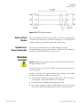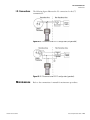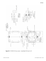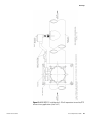
1
ConsistencyPRO Nuclear Density Detector / Transmitter User Guide P/N 900-000082 Revision F Part of Thermo Fisher Scientific ConsistencyPRO Nuclear Density Detector / Transmitter User Guide P/N 900-000082 Revision F © 2011 Thermo Fisher Scientific Inc. All rights reserved. “HART” is a registered trademark of the HART Communication Foundation. “Emerson” is a registered trademark of Emerson Electric Co. “FOUNDATION fieldbus” is a registered trademark of Fieldbus Foundation. All other trademarks are the property of Thermo Fisher Scientific Inc. and its subsidiaries. Thermo Fisher Scientific Inc. (Thermo Fisher) makes every effort to ensure the accuracy and completeness of this manual. However, we cannot be responsible for errors, omissions, or any loss of data as the result of errors or omissions. Thermo Fisher reserves the right to make changes to the manual or improvements to the product at any time without notice. The material in this manual is proprietary and cannot be reproduced in any form without expressed written consent from Thermo Fisher. This page intentionally left blank. Revision History Thermo Fisher Scientific Revision Date Comments 6/95 06-1995 Initial release for HART Communicator version (under P/N 900000072). 10/95 10-1995 Update for CE Mark. A00 03-1997 Modified to reflect address and company name changes. 00 03-2000 Changed P/N to 900-000082. Modified to reflect percent consistency applications only. A 08-2007 Revised per ECO 5917. B 08-2008 Revised per ECO 6520. C 12-2008 Revised per ECO 6721. D 09-2009 Revised per ECO 7126. E 01-2010 Revised per ECO 7253. F 09-2011 Revised per ECO 7808. ConsistencyPRO User Guide v This page intentionally left blank. Contents Safety Summary .................................................................................................. xi Safety Considerations ............................................................................. xi Safety Summary ..................................................................................... xi Intended Users ...................................................................................... xii Quick Setup ........................................................................................................xiii Thermo Fisher Scientific Chapter 1 Introduction ........................................................................................................ 1-1 Product Overview ............................................................................... 1-1 Principles of Operation ....................................................................... 1-1 Scintillation Detector ....................................................................... 1-3 Pulse Signal Conditioning ................................................................ 1-3 Microprocessor, ROM, Clock .......................................................... 1-3 External Connections ....................................................................... 1-3 Analog Output ................................................................................. 1-3 Process Temperature Conditioning .................................................. 1-4 Modem ............................................................................................ 1-4 RS423 Interface ............................................................................... 1-4 Power Supply ................................................................................... 1-4 Associated Documentation .................................................................. 1-4 Chapter 2 Installation ......................................................................................................... 2-1 General ............................................................................................... 2-1 Requirements for Consistency Applications ........................................ 2-2 Installation Considerations .................................................................. 2-2 Sampling .......................................................................................... 2-3 Voids or Air Entrainment................................................................. 2-4 Stratification .................................................................................... 2-4 Gamma Beam Sensitivity ................................................................. 2-4 Environment .................................................................................... 2-5 Electrical/Power Considerations ....................................................... 2-5 Wiring ................................................................................................ 2-6 Removing the Terminal Compartment Cover .................................. 2-6 Sensor Connections.......................................................................... 2-7 Analog HART Output ..................................................................... 2-8 Bell 202 Lease Line Communications .............................................. 2-9 Communication Speed/Modems ...................................................... 2-9 4-Wire Leased Line ........................................................................ 2-10 ConsistencyPRO User Guide vii Contents 2-Wire Leased Line ........................................................................ 2-10 4-Wire Leased Line Multiple Remote Sites..................................... 2-11 Automatic Dial-Up ........................................................................ 2-11 Multi-Drop Communications ........................................................ 2-12 RS423 Digital Connection ............................................................. 2-12 Optional Alarm Module................................................................. 2-13 Optional Loop-Powered Indication ................................................ 2-13 Hazardous Locations ......................................................................... 2-13 Shock & Vibration Environments ..................................................... 2-14 viii Chapter 3 Start-Up Testing................................................................................................. 3-1 General ............................................................................................... 3-1 Equipment & Loop Test ..................................................................... 3-2 Device Test ...................................................................................... 3-2 Loop Test ......................................................................................... 3-3 Reviewing Configuration Data ............................................................ 3-4 Chapter 4 Device Setup ...................................................................................................... 4-1 PV....................................................................................................... 4-1 Application Select – Auto Setup .......................................................... 4-2 Manual Setup ...................................................................................... 4-2 Basic Setup ....................................................................................... 4-2 Tag ............................................................................................... 4-2 Range & Units .............................................................................. 4-2 Date & Time ................................................................................ 4-4 Damping ....................................................................................... 4-4 AO Alarm Type ............................................................................ 4-5 Detailed Setup ................................................................................. 4-6 Temperature Compensation.......................................................... 4-6 Output Trim................................................................................. 4-7 Field Device Information .............................................................. 4-9 Diag/Service ...................................................................................... 4-10 Calibration ..................................................................................... 4-10 General ....................................................................................... 4-10 Auto Reference & Calibration ..................................................... 4-11 Manual Reference & Calibration ................................................... 4-12 Process Samples ........................................................................... 4-14 Density Offset ............................................................................. 4-14 Review .............................................................................................. 4-15 Menu Charts ..................................................................................... 4-15 Chapter 5 Maintenance ...................................................................................................... 5-1 Chapter 6 Troubleshooting & Service ............................................................................. 6-1 Communicator Diagnostics................................................................. 6-1 ConsistencyPRO User Guide Thermo Fisher Scientific Contents Service & Returns ............................................................................... 6-1 Warranty ............................................................................................. 6-2 Thermo Fisher Scientific Appendix A Ordering Information ....................................................................................... A-1 Appendix B Specifications................................................................................................... B-1 Appendix C The 275 Communicator.....................................................................................C-1 Introduction....................................................................................... C-1 User Interface ..................................................................................... C-1 The Display .................................................................................... C-2 Function Keys ................................................................................. C-2 On/Off Key .................................................................................... C-3 Hot Key .......................................................................................... C-3 Arrow Keys ..................................................................................... C-3 Alphanumeric Keypad ..................................................................... C-4 Shift Keys ........................................................................................ C-4 Connections ....................................................................................... C-4 Load Resistor Connection ............................................................... C-5 I.S. Port Connection ....................................................................... C-5 Maintenance ...................................................................................... C-6 Software Diagnostics .......................................................................... C-6 Communicator Diagnostics............................................................. C-6 ConsistencyPRO Diagnostics .......................................................... C-9 Appendix D The 375 Communicator.................................................................................... D-1 Introduction....................................................................................... D-1 User Interface ..................................................................................... D-1 The Display .................................................................................... D-1 Keys ................................................................................................ D-2 Multifunction LED ......................................................................... D-2 Connections ....................................................................................... D-3 Connecting to a HART Loop ......................................................... D-3 Connecting Directly to HART Device ............................................ D-4 Connecting to the Load Resistor ..................................................... D-4 I.S. Connections.............................................................................. D-5 Maintenance ...................................................................................... D-5 Software Diagnostics .......................................................................... D-6 ConsistencyPRO Diagnostics .......................................................... D-9 Appendix E Drawings ............................................................................................................ E-1 Appendix F Toxic & Hazardous Substances Tables........................................................ F-1 ConsistencyPRO User Guide ix This page intentionally left blank. Safety Summary This chapter contains information that must be read and understood by all persons installing, using, or maintaining this equipment. Safety Considerations Failure to follow appropriate safety procedures or inappropriate use of the equipment described in this manual can lead to equipment damage or injury to personnel. Any person working with or on the equipment described in this manual is required to evaluate all functions and operations for potential safety hazards before commencing work. Appropriate precautions must be taken as necessary to prevent potential damage to equipment or injury to personnel. The information in this manual is designed to aid personnel to correctly and safely install, operate, and/or maintain the system described; however, personnel are still responsible for considering all actions and procedures for potential hazards or conditions that may not have been anticipated in the written procedures. If a procedure cannot be performed safely, it must not be performed until appropriate actions can be taken to ensure the safety of the equipment and personnel. The procedures in this manual are not designed to replace or supersede required or common sense safety practices. All safety warnings listed in any documentation applicable to equipment and parts used in or with the system described in this manual must be read and understood prior to working on or with any part of the system. Failure to correctly perform the instructions and procedures in this manual or other documents pertaining to this system can result in equipment malfunction, equipment damage, and/or injury to personnel. Safety Summary The following admonitions are used throughout this manual to alert users to potential hazards or important information. Failure to heed the warnings and cautions in this manual can lead to injury or equipment damage. Warning Warnings notify users of procedures, practices, conditions, etc. which may result in injury or death if not carefully observed or followed. The triangular icon displayed with a warning varies depending on the type of hazard (general, electrical, radiation). Thermo Fisher Scientific ConsistencyPRO User Guide xi Safety Summary Intended Users Caution Cautions notify users of operating procedures, practices, conditions, etc. which may result in equipment damage if not carefully observed or followed. Note Notes emphasize important or essential information or a statement of company policy regarding an operating procedure, practice, condition, etc. Intended Users This publication is for technical personnel responsible for the installation, operation, and maintenance of this product. These individuals include: xii ConsistencyPRO User Guide Installation personnel: Should be an electrician or a person with a solid background in electronic instrumentation. The person should be familiar with the National Electrical Code (NEC), proper grounding and safety procedures, and local wiring regulations. Handling of the source and source housing must be conducted or supervised by a licensed individual. Operating personnel: Should have knowledge of the process and should read and understand this guide before attempting any operating procedure. Maintenance personnel: Should have a background in electricity and be able to recognize shock hazards. Personnel should also be familiar with electronic process control instrumentation and have a good understanding of troubleshooting procedures. Thermo Fisher Scientific Quick Setup This procedure takes you through the auto setup function. This is adequate for most percent consistency applications. For additional information, refer to the remainder of this guide. The procedure assumes that the gauge has been correctly installed and the communicator is properly connected (see Chapter 2). It also assumes that the start-up tests have been performed (see Chapter 3). 1. Turn on the communicator and go to Device Setup > Application Select > %Cs Auto Setup. The communicator asks you to set the loop to manual if you have not already done so. 2. Enter the following information when prompted: date, time, unit tag, output at 4 mA, output at 20 mA, and pipe ID. 3. Enter the auto reference cycle. 4. When prompted, obtain three samples, which will be used to determine the actual process %Cs in a lab (to be used as part of the first calibration point in the calibration curve). Ensure the temperature sensor is properly connected and functional. 5. The value of the process temperature at the time of referencing is entered automatically as a reference temperature. The default time constant for one reference cycle is 30 seconds. Total sample time is ten times the reference time constant. 6. After the first 30 seconds, the system checks if the process was stable. If it was, the system will complete the remaining nine reference cycles. If the process was not stable, you are alerted to the fact first, then prompted to accept or reject the reference. 7. When you accept the reference, you are prompted to enter the lab result of the samples taken during the reference. 8. The system then calculates the second point on the calibration curve, which is the lab result plus 5% consistency. You are prompted to accept the calibration. When you do so, you can return the loop to automatic control. Thermo Fisher Scientific ConsistencyPRO User Guide xiii This page intentionally left blank. Chapter 1 Introduction Product Overview The Thermo Scientific ConsistencyPRO gamma density system is a microprocessor-based instrument that consists of the following major components: Density detector/electronics (transmitter) Gamma source Vibration collar RTD or external temperature transmitter These components are externally mounted and provide consistency information without contacting the process material. This transmitter is designed for compatibility with the HART communicator interface. The communicator can be used to interrogate, configure, test, or format (reference and calibrate) this transmitter. It can communicate with the transmitter from the control room, the transmitter site, or any other wiring termination point in the output loop. Principles of Operation The system is based on the principle of gamma ray absorption by the process material to be measured. The transmitter is mounted on the process pipe opposite its companion source housing. The gamma rays emitted by the source are detected by a plastic scintillator-photomultiplier tube combination, and the resulting pulses are counted to determine the degree of absorption by the process material. The count is then processed by the microprocessor to provide an output. The instrument provides a standard 4–20 mA output. In addition, a digital output using the HART communications protocol is superimposed on the analog output or read via an intrinsically safe local transmitter connection. Alternatively, digital communication may be established via a separate RS423 port on the transmitter. All calibration and configuration data can be read or written through any of these communications ports. The instrument requires a process temperature input for temperature compensation or temperature correction of the main process variable output. This input can be either an RTD or a 4–20 mA temperature transmitter. Thermo Fisher Scientific ConsistencyPRO User Guide 1-1 Introduction Principles of Operation Figure 1–1. ConsistencyPRO block diagram 1-2 ConsistencyPRO User Guide Thermo Fisher Scientific Introduction Principles of Operation Scintillation Detector The scintillation detector assembly consists of the plastic scintillator, the photomultiplier tube (PMT), and a pre-amplifier. Each gamma ray striking the scintillator produces a flash of light, which is converted by the PMT into a brief current pulse. The pre-amplifier amplifies the pulses to a level suitable for passing on to the signal conditioning circuit. Pulse Signal Conditioning The pulse signal conditioning circuit detects all pulses above predetermined thresholds, which are dependent upon the type of gamma source installed. These counts are passed on to the microprocessor for further processing. The ratio of the two counts is used to stabilize the gain of the PMT against temperature fluctuations, while the larger of the two counts provides the raw density signal. Microprocessor, ROM, Clock The microprocessor includes an onboard nonvolatile memory (EEPROM), which stores all calibration and configuration data for the instrument. The microprocessor is responsible for: Performing unit calculations and temperature compensation of the process variable Controlling the PMT gain Communicating with external host devices Performing diagnostic self-testing The software and all factory default constants reside in EPROM. A realtime clock is included to allow for source decay compensation. This clock is not protected against power failure. External Connections External connections are provided for power, analog output, process temperature input, RS423 communications, and intrinsically safe communications. Each set of connections is isolated from all other connections to the instrument, with the exception of the intrinsically safe output, which is connected to ground. Analog Output The analog output circuitry converts the process variable produced by the microprocessor into a standard 4–20 mA analog signal. In addition, it superimposes the HART communication signal onto this analog output. Thermo Fisher Scientific ConsistencyPRO User Guide 1-3 Introduction Associated Documentation Process Temperature Conditioning Modem The HART protocol specifies the Bell-202 standard as the signal carrier. The digital signal to and from the microprocessor is converted by the modem section into a Bell-202 signal. This signal is then routed to the analog current output and to the intrinsically safe connections. RS423 Interface In addition to the Bell-202 interface, the instrument also communicates digitally using the RS423 standard. Power Supply Associated Documentation 1-4 The process temperature signal conditioning circuitry accepts a signal from a 3-wire RTD, a self-powered 4–20 mA temperature transmitter, or an externally powered 4–20 mA transmitter. This circuitry then converts the temperature signal into digital form for use by the microprocessor. ConsistencyPRO User Guide The instrument can be powered by 90–250 Vac, 50/60 Hz or by 18–36 Vdc. The incoming voltage is filtered against conducted noise, transformed and rectified if necessary, and applied to a switching power supply input. The switching power supply allows operation over the very wide continuous input range specified and provides regulated, isolated power for all circuits in the instrument. When the unit is AC powered and a DC backup is provided, if the AC voltage drops out of range, the transmitter will automatically switch to the DC backup power. This switch takes place with no loss of signal. Once the AC power is restored, the transmitter reverts to it for power supply. A separate circuit generates a variable highvoltage supply for the photomultiplier tube. In addition to this guide, the Gamma Radiation Safety Guide (p/n 717904) must be read and understood by all persons installing, using, or maintaining this equipment. Thermo Fisher Scientific Chapter 2 Installation General This section describes the recommended installation procedures for consistency applications. If these procedures are inadequate for a particular consistency application, consult Thermo Fisher Scientific for specific recommendations. In all cases, radiation safety has been a primary concern in the design and manufacture of the unit. The ConsistencyPRO gauge presents no personnel hazards in either installation or operation if all procedures are followed correctly. Except for the small beam port, the gamma source is completely surrounded by lead and steel shielding. The beam port is equipped with a movable lead shutter block. The source unit is shipped with the source shutter locked in the OFF position. Warning The source shutter must remain in the locked position until the installation has been completed and the equipment is ready for start-up and calibration. Warning Only a licensed individual may commission the source for use. Consult Thermo Fisher for information or assistance. Note In addition to the figures in this chapter, reference the drawings in Appendix E. Thermo Fisher Scientific ConsistencyPRO User Guide 2-1 Installation Requirements for Consistency Applications Requirements for Consistency Applications The answer to each of the following questions must be YES for proper gauge operation. 1. Is minimum process pressure 25 psig or more? 2. Is pipe size 6” or greater? 3. Is % consistency 2 % or greater? 4. Does the temperature input device use thermowell? 5. Is vibration isolation mount used? 6. Are there 10 pipe diameters of clear, straight pipe prior to the gauge? 7. If mounting on a horizontal pipe, is the gauge horizontal? 8. Is there a sample valve within two pipe diameters downstream of the gauge? 9. Is the variation of ash or liquor solids less than 1%? 10. Is entrained air constant? Installation Considerations To ensure proper operation of the system, carefully plan the location of the system installation. A number of factors concerning both ease of calibration and system accuracy should be considered before the system is permanently installed. Transmitter installation consists of mounting the vibration collar to a stable non-vibrating section of floor or support structure. A vibration collar consists of two sections of pipe that are clamped around the process pipe to prevent contact and the transmission of vibration from the process pipe. The recommended system location is on a vertical pipe with upward flow that is at least ten straight pipe diameters downstream of any elbows, valves, or reducers. Line pressure should be 25 psig or greater. It is also necessary to take into account the need for access to the transmitter and source housing. 2-2 ConsistencyPRO User Guide Thermo Fisher Scientific Installation Installation Considerations The source housing should be mounted with the shutter handle on the right hand side when the source housing is viewed from the rear. Following are examples of mounting configurations. Your particular configuration may be different. Figure 2–1. Mounting configurations Note Refer to Appendix E for other application drawings. Sampling Thermo Fisher Scientific In all cases, initial system calibration will consist of collecting samples of the product and comparing the laboratory analysis of the sample with the transmitter signal reading. Users should use/follow the TAPPI approved sampling procedure for all sampling and sample collecting. A number of samples throughout the consistency range of the process will provide an accurate correlation between product consistency and system response. It is important that the sample be drawn as close to the transmitter as possible to ensure that it is representative of the product being measured by the system. Thus, when possible, the installation should include a nearby sample valve that can take samples from the middle of the sample stream. ConsistencyPRO User Guide 2-3 Installation Installation Considerations Voids or Air Entrainment Air in the process line will cause the system to indicate a product consistency different from the laboratory analysis. The pressure in the line must be 25 psig or higher to minimize the effects of any entrained air. The effect of air entrainment occurs because the density of a void is many times lower than that of any actual material being measured. Therefore, even a small amount of air entrainment will displace enough product to cause low and unstable consistency indications. To prevent air entrainment in the process, check all seals and pipe connections. If the gauge is to be mounted near a pump, place it upstream of the pump on the suction side. Being on the suction side of the pump eliminates the possibility of the gauge seeing air that might be introduced to the process stream by the pumping action. There must be a minimum of five pipe diameters upstream of the pump inlet. When it is physically impossible to mount the gauge upstream of the pump, a downstream mounting may be permissible, but additional considerations must be observed. In this situation, the gauge must be mounted a minimum of 10 pipe diameters downstream of the pump or any elbow valves or reducers. This length of pipe run is usually adequate to allow the reestablishment of normal flow following the disruptions caused by the devices mentioned previously. Maintaining a line pressure of 25 psig or greater reduces the effects of entrained air by collapsing the bubble and forcing the air into solution in the water, eliminating the void. 2-4 Stratification When dealing with consistency, another factor to consider is stratification of the product. Keeping the product as homogeneous as possible will prevent errors in measurement between the laboratory analysis and the transmitter reading. Maintain the process velocity so that the mixture of solids and liquids remains as homogenous as possible. Mounting the gauge on a vertical pipe section with upward flow is recommended, as such a mounting arrangement will help keep the product uniform. If a horizontal pipe must be used, mount the detector and gamma source so that the centerlines of both are horizontal. Gamma Beam Sensitivity Because the instrument is highly sensitive to small changes in gamma beam intensity, ensure that the detector only measures radiation generated from the correct gamma source. ConsistencyPRO User Guide Thermo Fisher Scientific Installation Installation Considerations Environment Electrical/Power Considerations The environment must also be considered prior to installation. The transmitter must be mounted in such a way that ambient temperature changes are minimized. The ambient temperature operating limits of the transmitter are -4°F to +122°F (-20°C to +50°C). Vibration, mechanical shock, and external contact with corrosive materials must be avoided. The signal terminals are located in a compartment of the transmitter housing separate from the transmitter electronics. Connections for the communicator are accessible through an external I.S. plug on the side of the terminal housing. All conduit connections should be properly installed to prevent moisture from entering the terminal compartment. Figure 2–2. Terminal strip – electrical connections The instrument may be powered by AC line power or from a DC supply. The transmitter will operate on 90–250 Vac with no alteration required to the input connections. Line frequencies from 45 to 60 Hz are acceptable. Live and neutral connections are made to the terminals marked ACH and ACN on the terminal strip, and a separate ground connection may be made to the Earth stud in the terminal compartment. The DC supply can vary between 18 and 36 V, nominally 24 Vdc. The supply is connected to the terminals marked +DC and -DC on the terminal strip. Note The - DC terminal is connected directly to the instrument chassis. Negative ground DC supply must be used. Voltage and polarity must be strictly observed. Thermo Fisher Scientific ConsistencyPRO User Guide 2-5 Installation Wiring Either or both AC and DC supplies may be connected to the transmitter at any time. The transmitter will draw power from whichever source gives the higher DC voltage (in the case of AC line power, after transformation and rectification). For instance, the transmitter may be normally powered by AC line power and be backed up by a standby 24 V battery supply to guard against power failures with no additional switching required. The transmitter uses internal filtering to prevent interference from the input power. However, for optimum reliability, use fused, smoothed, and filtered power sources. The maximum power requirements of the transmitter are 15 VA maximum for both AC and DC. The input voltage is protected by fuses FS1 and FS2. Both are rated at 1 amp, type “F” (Fast Blow). Wiring Removing the Terminal Compartment Cover The terminal compartment cover must be removed to access the signal terminals. 1. Loosen the 12 captive screws holding the cover in place. The screws are captivated in the cover and cannot be removed. 2. Use the four set/jack screws on the terminal cover to break the cover free from the transmitter. Turn each of the set/jack screws a few turns clockwise until the gasket seal breaks. 3. Remove the cover. Do not use a screwdriver or other tool to pry off the cover. 4. To replace the cover, turn the set/jack screws back so that they are recessed from the inside surface of the cover. Push the cover back in place and cross-torque or alternately tighten the captive screws. 2-6 ConsistencyPRO User Guide Thermo Fisher Scientific Installation Wiring Sensor Connections The transmitter will accept a 4–20 mA temperature or 100-ohm platinum RTD input. A temperature input is required for consistency applications. Optional sensors available from Thermo Fisher include a surface mount RTD, a 1-inch (25 mm) thermowell, and a 2.5-inch (37.5 mm) thermowell. Figure 2–3 shows the possible connections for both sensor types. Figure 2–3. Temperature sensor connections If the transmitter is mounted remotely from a RTD, operation will be within specifications for lead wire resistance of up to 10 ohms per lead. The leads between the RTD and the transmitter should be shielded. If only two leads are used on the RTD, both are in series with the sensor element, so significant errors – greater than 1% – can occur if the lead lengths exceed 20 feet of 20 AWG wire. The temperature sensor should be located close to the density measurement point for best accuracy. If the sensor is a 4–20 mA transmitter, its current loop output can be powered either from the instrument or by an external power supply. The voltage available to drive the current loop from the instrument is 10 volts minimum. The input load presented by the instrument when the temperature transmitter is externally powered is 240 ohms in series with a 2.0 V constant voltage device. The sensor input terminals on the instrument are electrically isolated from all other connections with a maximum common-mode voltage limit of 500 volts. This allows the sensor input wiring to be separately grounded. The transmitter will operate with input either floating or grounded, but to Thermo Fisher Scientific ConsistencyPRO User Guide 2-7 Installation Wiring guard against induced noise, it is preferable to ground the wiring at one point. In an externally powered system this may be at the power supply negative terminal; otherwise the instrument 0V terminal (terminal #9) is a suitable point. If shielded wiring is used, ground the shield at the same point as the rest of the wiring. Analog HART Output The density output is provided by the transmitter in the form of an industry standard 4–20 mA current loop signal. Superimposed on this is the HART digital signal that provides two-way digital communication with the transmitter. The analog output may be connected directly to a remote indicator, recorder, or control system if required. The dc voltage available from the instrument output terminals to drive the current loop is a minimum of 10 volts. Alternatively, an external power source may be connected in series with the loop to increase the available drive voltage. The maximum voltage that can be connected in this way is 24 volts, so that the maximum loop drive voltage is 34 volts. The analog output terminals are electrically isolated from all other connections with a maximum common mode voltage of 500 volts. This isolation allows the current loop to be grounded at any convenient point. Caution The minimum resistance in the loop external to the transmitter is 250 ohms. This resistance is required by the HART protocol. The maximum load resistance that can be driven by the transmitter with no external voltage supply is 500 ohms. If a 375 Field Communicator is used, it may be necessary to install an Emerson Model 340 HART filter in the 4–20 mA loop signal. This is not required if an older communicator (268 or 275) is used. Figure 2–4. Analog output connections 2-8 ConsistencyPRO User Guide Thermo Fisher Scientific Installation Wiring Bell 202 Lease Line Communications For certain remote locations it may be desirable to take advantage of the communications capability resident in the system. The system provides standard HART protocol communication on a Bell 202 signal superimposed on the 4–20 mA DC output. This output can be directly coupled into a remote telemetry unit (RTU). It is possible to couple the instrument directly to standard communication equipment common to lease line operations without the need for an RTU. A standard Bell 202 modem can be directly connected to the other end of the lease line and interfaced with a PLC, PC, or other host. Consult Thermo Fisher for documentation on the HART protocol. Communication Speed/Modems HART transmitters communicate at 1200 baud. The return of a Process Variable (PV) value when polled by the host occurs once every half second. For multi-drop installations, the time to inquire and receive a PV value from a particular device can be determined from the following relation: seconds to receive PV value = number of transmitters / 2. A number of Bell 202 modems may be interfaced with devices using the HART protocol. The equipment list provided is for information only. Recommendation of a specific supplier should not be implied. Table 2–1. Manufacturer Model Number Application Racal-Vadic VA1251G Leased line only Universal Data UDS202T Leased line only Codex 2219 Leased line dial-up Modem Settings Thermo Fisher Scientific Terminal Control Disabled Soft Carrier Timing Disabled Turn-around Time Disabled Local Copy Disabled Line Configuration 2-wire Clear to Send Delay 8.3 ms Received Data in Digital Loopback RX Disabled Carrier Detect Timing 6ms to ON /6ms to OFF Data Set Ready Control Disabled Constant Carrier Disabled Transmitter Output Level -4 dBm ConsistencyPRO User Guide 2-9 Installation Wiring 4-Wire Leased Line A 4-wire leased line installation is recommended particularly for unconditioned phone lines. The figure below shows the equipment and connections that can be used. The equipment identified is for example only. Recommendation of a specific supplier should not be implied. Figure 2–5. 4-wire leased line 2-Wire Leased Line The equipment identified is for example only. Recommendation of a specific supplier should not be implied. Note The 7201 is required only for lines with large losses. The 5 MFD capacitor shown in Figure 2–6 is not required when the 4421 is used. Note A 600-ohm coupling transformer can be used in place of the Tellabs equipment where phase distortion is an issue. Figure 2–6. 2-wire leased line 2-10 ConsistencyPRO User Guide Thermo Fisher Scientific Installation Wiring 4-Wire Leased Line Multiple Remote Sites The equipment identified is for example only. Recommendation of a specific supplier should not be implied. The section titled “Multi-Drop Communication” defines how multiple transmitters can be configured to operate on one communication line. Figure 2–7. 4-wire leased line multiple remote sites Automatic Dial-Up The equipment identified is for example only. Recommendation of a specific supplier should not be implied. Figure 2–8. Automatic dial-up Thermo Fisher Scientific ConsistencyPRO User Guide 2-11 Installation Wiring Multi-Drop Communications The instrument supports HART multi-drop communication. Up to 15 transmitters may be connected in parallel across a single loop pair and may be separately addressed. Refer to the figure below. In this case, setting the transmitter address to a nonzero value enables multi-drop mode and forces the analog output to 4 mA. No analog 4–20 mA signal is available from multi-dropped transmitters. Figure 2–9. Multi-drop communications RS423 Digital Connection It is possible to communicate with the instrument over a separate port that uses the EIA RS423 data communication standard. This port provides a three-wire medium in which one wire carries the transmitted signal, one carries the received signal, and the third is the common return. Figure 2–10 shows these connections. The communication data rate used is 1200 bits per second. This rate allows communication up to a maximum cable length of 3000 feet. The software protocol is identical to the HART protocol. The RS423 terminals are electrically isolated from all other connections with a maximum common-mode voltage limit of 500 volts. The link will operate either floating or grounded, but to guard against induced noise the common return should be grounded at a convenient point, normally at the connection to the remote host. Shielded cable should be used for long runs with the shield grounded at the same points as the common return. 2-12 ConsistencyPRO User Guide Thermo Fisher Scientific Installation Hazardous Locations Figure 2–10. RS423 digital connection Optional Alarm Module Optional LoopPowered Indication Hazardous Locations The optional alarm module is provided with a universal mounting bracket. The unit may be mounted on a 2-inch (50 mm) pipe or on a flat wall. Two conduit openings are provided for input and output wiring. The loop-powered indication is provided to display consistency information along any remote point in the 4–20 mA loop. The indication may be mounted in the field or in a control room. Caution Individual transmitters are clearly marked with a label indicating the approvals they carry. For future orders, contact Thermo Fisher for the most current information on these approvals. In order to conform to the expected explosion proof rating for the installed transmitter, the following conditions must be met: Thermo Fisher Scientific At least six threads must be engaged on the end cap. The cover must be on hand-tight, and the threads must not be damaged. Conduits must be installed with the appropriate seals. If one of the conduit connections on the housing is not used, it must be closed with a threaded metal plug with at least five threads engaged. ConsistencyPRO User Guide 2-13 Installation Shock & Vibration Environments Shock & Vibration Environments The source housing is a heavy, lead-filled container that holds and shields the radioactive source. The detector contains a PM tube that can be damaged if subjected to excessive vibration. In all consistency applications, the unit must be mounted on a vibration collar. Typical installations that can involve high levels of shock and vibration include, but are not limited to an installation near a large pump that causes the pipe to vibrate excessively or a blowline in a pulp mill having high levels of vibration. Warning If you have an application with vibration or shock level similar to the examples mentioned above, contact Thermo Fisher to review the installation. Failure to heed this warning may cause mechanical failure. 2-14 ConsistencyPRO User Guide Thermo Fisher Scientific Chapter 3 Start-Up Testing General Before putting the instrument into operation, you should test it using the communicator. This process consists of testing the transmitter and loop and verifying transmitter configuration data. To test on the bench, hook up the transmitter and the communicator as shown in Figure C–2 for the 275. Alternatively, you can plug the communicator directly into the access port located on the side of the terminal compartment. A source of gamma radiation will be required for the detectors and high voltage circuits to stabilize. For the 375, refer to Figure D–2. After the bench check, connect the equipment as shown in Figure 3–1. Press the On/Off key to turn on the communicator. The communicator will display its software revision level and conduct a self-test. If a transmitter is detected, the communicator briefly displays the online menu. Note Specific screens are not provided in this chapter, as screen appearance differs between the 275 and 375 communicators; however, the general start-up testing and processes are the same. If a “Device Disconnected” message appears, check the connections and retry. Note If the transmitter is not communicating and loop connections are correct, it could be that the transmitter is operating in the multi-drop mode. To determine this, access the poll function (refer to the communicator’s user manual). If the poll function cannot locate any transmitters in the loop, or if any other error message appears, refer to the diagnostics sections of Appendix C for the 275 or Appendix D for the 375. Thermo Fisher Scientific ConsistencyPRO User Guide 3-1 Start-Up Testing Equipment & Loop Test Figure 3–1. Bench hookup Equipment & Loop Test Device Test Although the status of the transmitter is included in every communication between the transmitter and communicator and the user is notified if a failure is detected, the user-initiated test functions verify that the transmitter, the communicator, and the loop are working properly. Testing is recommended whenever you suspect component failure or a problem with loop performance. In most cases, these tests can isolate a problem to the subassembly level. To initiate the test functions, go to the Device Setup menu and enter the Diag/Service submenu. From this submenu, you can perform a device test or a loop test. The instrument performs continuous self-diagnostics and notifies the communicator of its status with every communication message. A more extensive diagnostic routine can be initiated with the device test function. This routine can identify a failure down to the subassembly level. Note A message will appear reminding you to set the loop to manual because these tests can affect the output of the transmitter. If the transmitter is being tested on the bench and is not connected to the control loop, this is unnecessary. If the transmitter passes the test, a message is displayed indicating that the test is complete and the transmitter passed. If a problem is detected, a message indicating the source of the problem is displayed. Refer to the diagnostics sections of Appendix C for the 275 or Appendix D for the 375. You may perform other tests or end the test session. After you exit, return the loop to automatic control. The display then returns to the top-level function screen (online menu). 3-2 ConsistencyPRO User Guide Thermo Fisher Scientific Start-Up Testing Equipment & Loop Test Loop Test The loop test allows you to verify the output of the transmitter, the integrity of the loop, and the operation of any recorders or similar devices. Note A message will appear reminding you to set the loop to manual. Do so before continuing with the test. 1. When prompted, select a discrete mA level for the transmitter to output. You can select 4 mA, 20 mA, or a value between 4 and 20 mA (Other). If you enter a value not between 4 and 20 mA, an error message appears. 2. Use a current meter installed in the test loop to verify that it is reading correctly. If so, press or tap OK. If the output is not correct, the transmitter requires a digital trim. The display returns to the loop test screen and allows you to choose another output value. 3. After completing the loop test, return to the loop test menu previously shown and press or tap OK. The communicator notifies you that it is returning the transmitter to its original output. 4. The display then returns to the test function menu. Press or tap OK again. The display prompts you to return the loop to automatic control. Do so, and press or tap OK. This returns you to the top-level function menu. Thermo Fisher Scientific ConsistencyPRO User Guide 3-3 Start-Up Testing Reviewing Configuration Data Figure 3–2. Loop test flowchart Reviewing Configuration Data 3-4 ConsistencyPRO User Guide It is a good idea to review the configuration parameters currently stored in the transmitter. To do so, go to the online menu and select Device Setup > Review. You can step through all the configuration data and review each group in detail. Percent consistency is represented by %Cs in the menus. Thermo Fisher Scientific Chapter 4 Device Setup Note Specific screens are not provided in this chapter, as screen appearance differs between the 275 and 375 communicators; however, the steps for setting up the device are generally the same. When you apply power to the communicator, it will go through its start-up screens and perform a self-test. If it is properly connected to the instrument, the communicator will then display the Device Setup menu. The Device Setup menu contains five submenus: PV (process variables), Application Select, Manual Setup, Diag/Service, and Review. Charts illustrating the structures of several menu and submenus are provided at the end of this chapter. PV There are five menu items within the PV submenu. 1. PV: Provides access to the process variables for viewing output variable values in the selected unit of measure. 2. PV % rnge: Shows the percentage of the selected range of output. 3. PV Output: Shows the electric-current loop’s output value in mA. 4. PV Units: This item shows the selected output unit of measure. 5. Temp: Displays the process temperature. Thermo Fisher Scientific ConsistencyPRO User Guide 4-1 Device Setup Application Select – Auto Setup Application Select – Auto Setup The Application Select submenu displays four applications. For the ConsistencyPRO, select %Cs Auto Setup. Note There are two methods of setting up the instrument – auto setup and manual setup. It is recommended that you select the auto setup method if initially setting up the instrument or performing a recalibration. Manual setup is recommended only for adjusting individual parameters, not for performing full calibrations. 1. After selecting %Cs Auto Setup, the communicator asks you to set the loop to manual if you have not already done so. 2. Enter the following information when prompted: date, time, unit tag, output at 4 mA, output at 20 mA, and pipe ID. 3. Enter the auto reference cycle. See “Diag/Service” later in this chapter for a description of the auto referencing process. Manual Setup This submenu allows you to select a basic or detailed setup. Note Manual setup is recommended only for adjusting individual parameters, not for performing full calibrations. Basic Setup Tag Range & Units 4-2 ConsistencyPRO User Guide You can access the following items through the Basic Setup submenu: tag name, range and units, date and time, damping, and AO alarm type. The tag identifies the transmitter. It can be up to eight alphanumeric digits. One of the most common configuration changes involves reranging the transmitter’s 4 and 20 mA points. The following will take you through the process. Thermo Fisher Scientific Device Setup Manual Setup 1. PV Units: This menu item allows you to change the output unit of measure. The following units are available: SGU* g/cm3 kg/m3 lb/gal lb/ft 3 g/ml kg/L g/L lb/in 3 STon/yd 3 °Twad** °Brix** °Baum hv** °Baum lt** API % sol-wt % sol-vol % Cs SGU 15C *These options are for SGU and SGU15 applications. **These units are typically referenced to a specific temperature (i.e., 60°F). It is recommended that temperature compensation be on when these units are selected. 2. URV and LRV: Upper range value and lower range value. The URV menu item allows you to change the 20 mA set point, and the LRV item allows you to change the 4 mA set point. 3. USL and LSL: Upper sensor limit and lower sensor limit. USL displays the upper limit of the range and is equal to 10 %Cs. LSL displays the lower limit of the range and is equal to 0 %Cs. These are read-only values. Thermo Fisher Scientific ConsistencyPRO User Guide 4-3 Device Setup Manual Setup 4. Density of Carrier: From this menu item, you can view and/or change the current value for the density of the carrier. Note Carrier density must be less than the solids density. If it is not, the transmitter will return an error. 5. Density of Material: View and/or change the current value for the density of the material (solids) in g/cc. If changing the value, be sure to enter the values for percentage solids by weight (% sol-wt) and percentage solids by volume (% sol-vol) in g/cc. The default value is 1.53 g/cc. Date & Time The instrument automatically compensates for source decay. The internal clock must be set with the current date and time in order for the compensation to work. Note If power to the transmitter has been removed or interrupted, you will need to reset the time. The communicator will display a message indicating that the time has been corrupted. Generally, this is not a significant error, as the clock resets to midnight when power is restored. Damping The ConsistencyPRO uses an electronic damping time constant that can increase the response time of the transmitter to smooth the output when there are rapid input variations. 1. PV Damp: Signal damping should be used to average out variations in the process that occur continuously. Damping time should be long enough to eliminate these fluctuations in the output signal as necessary. In a control situation, the control loop should be tuned based on this value. Assign a PV damping value. The value must be in increments of 0.5 seconds. 4-4 ConsistencyPRO User Guide Thermo Fisher Scientific Device Setup Manual Setup 2. Adaptive Damping: Adaptive damping allows the instrument to track rapid process variations that cause the signal to exceed the defined threshold (i.e., 5% of span). This value may be used when longer damping times are being used and a step change in the process must be tracked. When the instrument observes a selected percent change, the damping time is reduced to the adaptive damping time for three adaptive damping time periods. Damping time then returns to the normal damping time. In most cases, this action will change the output to the changed process value in line with a real-time condition. Adaptive Damp Status: Access this menu to turn adaptive damping on or off. Adaptive Damping Value: Enter the adaptive damping time. The value must be smaller than or equal to the normal damping value. When required for percent consistency applications, recommended adaptive damping is 3 seconds. Damping Threshold: The threshold setting is displayed as a percentage of full scale output. Fast damping time is used by the instrument only if the output signal fluctuates beyond the threshold. If the change in process output exceeds the value and adaptive damping is turned on, the output will be tracked and smoothed using the fast damping value. Note The adaptive damping threshold should be set above the statistical fluctuation level so as to allow for only true process changes and not a statistical variation. AO Alarm Type Thermo Fisher Scientific The AO Alarm Type parameter allows you to select what state the current output assumes in the event of an alarm. The options are: Low (3.5 mA fault condition) High (21.8 mA fault condition) Hold last value. ConsistencyPRO User Guide 4-5 Device Setup Manual Setup Detailed Setup Temperature Compensation You can access the following items through the Detailed Setup submenu: temperature compensation, output trim, and field device information. 1. Temperature Compensation Status: A different temperature correction algorithm is used for percent consistency applications. Leave this parameters turned off. Turning this parameter on will introduce errors, as the unit will begin performing two corrections. 2. Temperature Units: This item will only be displayed if temperature compensation is on and a temperature compensation sensor is connected to the system. 3. Compensation Parameters: The only parameter used in a percent consistency application is a reference temperature. It is automatically entered during the auto-referencing process. If manual referencing is necessary, access this menu item to enter your specific reference temperature 4. Sensor Type: Access this item to use the instrument with temperature compensation to recalculate the measured density to a density at the reference temperature. The communicator will display the current external input for measuring temperature as selected. You can select RTD or 4–20 mA. a. RTD – Input Trim: The input trim function allows you to calibrate the external temperature input using an external resistance or current standard. The communicator will prompt you to enter input values at the keypad while applying precise ohm or mA inputs of the same value. You can choose a factory trim, which sets the values to the factory defaults, or choose a user trim, which uses the values you enter. If you choose to do a user trim, the communicator will prompt you to connect the low set point resistance to the transmitter at the external input terminal. The transmitter will then adjust its internal gain to correct the discrepancies between the value indicated on the communicator display and the actual input. Enter the exact reference value and continue. Then communicator will indicate that the low set point is being changed and accepted. Note If you use a precision resistance box, use 100 ohms for the resistance value, and enter the value “99.27” into the instrument. 4-6 ConsistencyPRO User Guide Thermo Fisher Scientific Device Setup Manual Setup The communicator will then prompt you to connect the high set point to the external input. Enter the exact high set point and continue. Note If you use a precision resistance box, use 138.5 ohms for the resistance value, and enter the value “137.2” into the instrument. Note Although this guide refers to zero and span reference inputs, the gauge can use any two known points within its input range. The allowable input range is 70–20 ohms for RTD inputs. For maximum accuracy, make the two reference points as far apart as possible. b. 4–20 mA: If you select the 4–20 mA external input, the communicator will prompt you to enter the temperatures that correspond to the 4 and 20 mA inputs. Once you do this, you can select to perform a factory or user trim. The procedure for a user trim is identical to the procedure described for trimming with an RTD except you will enter “4” for the reference value when a low set point (4 mA) is connected and “20” for the reference value when a high set point (20 mA) is connected. Note Although this guide refers to zero and span reference inputs, the gauge can use any two known points within its input range. The allowable input range is 3.5–20.8 mA for current inputs. For maximum accuracy, make the two reference points as far apart as possible. Output Trim After the microprocessor conditions the sensor signals, it outputs a digital word. The output digital-to-analog (D/A) circuitry converts the word to an analog signal for the 4–20 mA communications line. It may be necessary to check and trim this circuitry. The 4–20 mA trim function can also be used to make adjustment to allow for peculiarities of a particular readout device in the loop. To determine whether you need to trim the output, connect the communicator and a precision milliamp meter capable of reading ±1 µA as shown in Figure 3–1. Enter the loop test mode (described in Chapter 3), and drive the transmitter to a 4 mA output. Check the milliamp meter. The reading should be 4 mA ±3 µA. Next, drive the transmitter to a 20 mA output, and check the milliamp meter. The reading should be 20 mA ±3 µA. If the values on the meter exceed the tolerance range, trim the output. Thermo Fisher Scientific ConsistencyPRO User Guide 4-7 Device Setup Manual Setup Using the communicator, you can trim the D/A converter with a current meter or voltage meter. If using a current meter, choose D/A Trim. If using a voltage meter, or if your meter’s output display does not read out in 4–20 mA, select Scaled D/A Trim. D/A Trim 1. Connect a precision current meter capable of reading ±1 µmA, and wait for the communicator to confirm the connection. 2. Enter the value as shown on the milliamp meter. The communicator will ask if the output reading on the display is equal to that on the current meter. If the display reading is not within ±3 µA of the current meter reading, choose No. 3. Repeat step 2 until the readings are within ±3 µA. 4. Repeat this process to set the 20 mA point. Scaled D/A Trim 1. To trim the output using a voltage meter or other meter, connect the meter across a resistor in the loop. For best accuracy, use a precision resistor. 2. The communicator will indicate that it is setting the field device output and will then ask if the changes are correct. If the output reading on the display is not within ±3 µA converted to the scale of the meter, choose No. 3. Repeat step 2 until the readings are within ±3 µA. 4. Repeat this process to set the 20 mA point. 4-8 ConsistencyPRO User Guide Thermo Fisher Scientific Device Setup Manual Setup Changing the Reading 1. You can scale the 4–20 mA reading to correspond to the desired scaled reading by selecting Change within the Scaled D/A Trim menu. 2. Enter the meter reading that would be displayed with a 4 mA input signal. For example, the voltage across a 500-ohm resistor will be 2.000 V at 4 mA and 10.000 V at 20 mA (actual values displayed will be within ±1.5 mV of these theoretical values). 3. The communicator will then prompt you to enter the meter reading for the 20 mA input signal. Field Device Information The Field Device Information item allows you to set other information types into the transmitter. 1. Source Type: Select the type of source used – Cs-137, Co-60, or Am241. 2. Last Setup Location: This item shows you where the last setup location was. 3. Sensor Serial Number: This item shows the sensor serial number. 4. Universal Variables: This submenu contains three items – Manufacturer, Model, and Poll Addresses. The Manufacturer and Model items are read-only. The Poll Address item allows you to change the unit’s polling address. 5. Pipe Description: Enter a description that will help you identify the pipe upon which the gauge is installed. You can use up to 12 characters. 6. Pipe ID: Enter the pipe ID if required. 7. Process Description: Enter a description that will help you identify the process material being measured. You can use up to 28 characters. Thermo Fisher Scientific ConsistencyPRO User Guide 4-9 Device Setup Diag/Service 8. Message: The message may contain information such as transmitter location or service record. You can use up to 32 characters. 9. Descriptor: Use this field for additional information about the transmitter, such as use or location. You can use up to 16 characters. 10. Final Assembly Number: View or change the factory-set final assembly number. 11. Software Revision: View the software revision installed in the gauge. This information is required when calling Thermo Fisher for technical support. Diag/Service This menu provides access to the Test Device, Loop Test, and Calibrate items. The device and loop tests are discussed in Chapter 3. Calibrating the ConsistencyPRO consists of four parts: referencing, calibration curve, process sample, and density offset. Calibration General Calibration of the ConsistencyPRO involves establishing a linear calibration curve that relates detector signal to percent consistency in the process line. Although the calibration curve can consist of multiple linear segments connecting calibration points, it is generally a simpler, single linear segment defined by two data points. Each data point consists of a consistency value (D) and a corresponding signal value (S): [D1,S1], [D2,S2]. The signal value, Sn, is not an actual detector count value but rather the result of a simple equation that relates the signal value to the reference count. The signal value is calculated as follows: Sn = ln(countref/countn), where countn represents the detector count at calibration and countref represents the detector count at reference. For example, if the reference count is 400,000 and the gauge sees a detector count of 200,000 during the calibration process, the signal value under these conditions is: Sn 4-10 ConsistencyPRO User Guide = ln(400,000/200,000) = ln(2) = 0.6931 Thermo Fisher Scientific Device Setup Diag/Service If the lab reports that the samples taken during the above calibration are 3.5 percent consistency, then the calibration point is (3.5, 0.6931). In practice, the reference point is typically used as the first calibration point. So the first calibration point is: [Lab Result, Sn = ln(countref/countref)] [Lab Result, Sn = ln(1.0)] [Lab Result, 0.0]. Based on the reference count (countref) and the other process information the % Cs Auto Setup function, the gauge will always calculate the second calibration point at the reference consistency plus 5%. For example, if the Lab Result in the calculation immediately above is 3.6% consistency, the second calibration point is calculated at 8.6% consistency. Using these examples, the resulting calibration curve is ([3.6,0.0], [8.6,S2]). If you are not using the % Cs Auto Setup function, then the signal values must be derived manually. Auto Reference & Calibration The automatic reference and calibration functions are accessible through the Diag/Service menu. 1. When you enter the auto reference cycle, the communicator asks if the loop is set to manual control. Do so, if you have not already and return to this screen. 2. Enter the following information when prompted: the current date and time, the device tag number, the measurement span, and the pipe ID. 3. When prompted, obtain three samples, which will be used to determine the actual process %Cs in a lab (to be used as part of the first calibration point in the calibration curve). Ensure the temperature sensor is properly connected and functional. 4. The value of the process temperature at the time of referencing is entered automatically as a reference temperature. The default time constant for one reference cycle is 30 seconds. Total sample time is ten times the reference time constant. 5. After the first 30 seconds, the system checks if the process was stable. If it was, the system will complete the remaining nine reference cycles. If the process was not stable, you are alerted to the fact first, then prompted to accept or reject the reference. Thermo Fisher Scientific ConsistencyPRO User Guide 4-11 Device Setup Diag/Service 6. When you accept the reference, you are prompted to enter the lab result of the samples taken during the reference. 7. The system then calculates the second point on the calibration curve, which is the lab result plus 5% consistency. You are prompted to accept the calibration. When you do so, you can return the loop to automatic control. Manual Reference & Calibration To access the manual reference function, exit the Diag/Service menu and follow this path: Device Setup > Application Select > General Density > Calibration > Reference. Manual calibration enables you to build the calibration curve with more than two points or correct the point established during auto calibration. 1. Ensure the date and time are correct. 2. When you select Reference, the date and time of the last reference and the reference signal are briefly displayed. If you have not referenced the transmitter before, the factory default values are displayed. The date is also displayed beside the Last Reference menu item. 3. Counts: Access this item to view the last reference count rate. 4. Reference Material: Several selections are available for the reference material. For %Cs, scroll through the list and select Unknown. 5. New Reference: Access this item to begin the new reference. The communicator displays the length of time the procedure will take. The referencing cycle is ten times the damping value (selected through the Basic Setup menu). Note If the process variable is changing significantly, it may be better to repeat the referencing procedure over a longer time period by increasing the damping value. Be sure to return the damping to its original value after completing the procedure. It may also be necessary to change the reference condition to make it stable enough to be repeatable over time. 4-12 ConsistencyPRO User Guide Thermo Fisher Scientific Device Setup Diag/Service 6. When the reference procedure is complete, the communicator will display the new value and ask if you want to accept or reject it. If you reject the value, the communicator will return to the previous screen and reference value, where you may take another reference. If you accept the value, the communicator will make the change permanent and display the new reference time, date, and value. 7. To establish a calibration curve manually, go to Device Setup > Application Select > General Density > Calibration > Calibration Curve. The calibration curve is derived using the data collected during the sample operation (described in next section). Data pairs consist of the transmitter signal values for each of the samples matched to the corresponding lab %Cs value. In the %Cs application, typically two data pairs are required to construct the calibration curve. Note The communicator displays references to “density value.” Consider this as the %Cs value. 8. Select the curve point you want to change. You can change the density and signal values, but make sure that the pairs remain matched. When changing density, note that if a density value is set to zero, that data pair is ignored in the construction of the calibration curve regardless of the signal value. Additionally, the software does not accept a zero density value. The value must be at least “0.0001.” Select End Changes when finished changing the calibration points. The communicator asks if you want to accept or reject the changes. Accept the changes to establish the new curve. This will re-zero the offset so the relationship between the calibration curve and the reference is in a normalized condition. If you reject the changes, all changes will be discarded. Thermo Fisher Scientific ConsistencyPRO User Guide 4-13 Device Setup Diag/Service Process Samples You can collect data and obtain the signal value using the sample function if you are checking the factory calibration curve or establishing a new curve. 1. Sample: This item displays the sensor signal for the last sample signal. The sample value is the average signal values taken during the set duration time. The formula is: Sn = ln(countref/countn) 2. Sample Duration: The sample duration must be greater than or equal to the damping value. Note that a longer duration allows for samples that are more accurate. 3. New Sample: Ensure the process conditions are stable. When ready, start the sample process. Upon completion, the new sample sensor signal is displayed. Keep a list of these signals to compare with the density values determined in the lab. Each time you take a sample with the transmitter, the lab should analyze the %Cs of the same sample. Match the %Cs values determined by the lab with the corresponding transmitter sample sensor signal values. Note If the lab results vary by more than 0.2 %Cs, reject the samples and take new ones, as this indicates a problem with sampling or lab repeatability. Density Offset The offset function allows you to modify the calibration curve with an offset values. If the current density calibration curve is giving incorrect density values by a fixed amount, there are three ways to correct the problem: modify the calibration curve, reference the transmitter, or apply an offset. If you are unable to establish reference conditions, use the offset function to shift the entire calibration curve using an offset factor. Enter the offset factor in the process variable units shown on the screen. The maximum offset is ± 1.0. Note If you reference after you have selected the offset factor, the offset value will be reset to zero. Changing the calibration curve will also reset the offset to zero. 4-14 ConsistencyPRO User Guide Thermo Fisher Scientific Device Setup Review Review Menu Charts Thermo Fisher Scientific Through the Review item, you can step through all the configuration data and review each group in detail. Percent consistency is represented by %Cs in the menus. The following charts illustrate the Device Setup menu and the Basic and Detailed Setup submenus. ConsistencyPRO User Guide 4-15 Device Setup Menu Charts Figure 4–3. Device Setup menu 4-16 ConsistencyPRO User Guide Thermo Fisher Scientific Device Setup Menu Charts Figure 4–4. Basic and Detailed Setup menus Thermo Fisher Scientific ConsistencyPRO User Guide 4-17 This page intentionally left blank. Chapter 5 Maintenance Every six months, perform a physical inventory of the sources and check the shutter. Use the form on the following page as a guide to perform these checks. Thermo Fisher Scientific ConsistencyPRO User Guide 5-1 This page intentionally left blank. Am-241-Be Assay: Status: Date: Measured <0.05 uCi Comments: In storage (5) Overall Condition: Verified by: (4) Shutter Operation: (3) Shutter lock: (2)On/Off Indicator: (1) Nameplate: Needs to be replaced Severe corrosion Mild to moderate corrosion Okay Response Survey Missing Stuck off Stuck on Needs lubrication Needs cleaning Okay Needs to be replaced Okay Needs to be replaced Needs cleaning Okay Needs to be replaced Needs cleaning Okay Five Point Safety Check Instructions: This form is/may be used to record the visual inspection and leak testing of a nuclear gauge. A preprinted inventory label may be placed over the user and product information blanks for convenience. When this form is used for leak test certification, the survey meter information must be completed. As you complete the inspection, check all of the blanks that apply. Use comments to document the findings and/or recommended corrective actions as needed. Signature: Name: Company: Performed By Measure >0.05 uCi Contact RSO Not performed Leak Test Background: Cal Date: Locked off Model: Serial: Unlocked Mounted but not in use: In use Brand: Survey Meter (required for leak test certification only) Activity: Co-60 Analyzer Tag: Isotope: Insertion source Location: Strip source Model: Serial: Weigh scale Density State: Brand: Continuous level City: Neutron backscatter Dual point level Address: Product Point level Company: Cs-137 Application: User Zip: System Information Gauge Inspection and Leak Test Certificate This page intentionally left blank. Chapter 6 Troubleshooting & Service Communicator Diagnostics Service & Returns Refer to the Software Diagnostics section in Appendix C (for 275 communicator) or Appendix D (for 375 communicator). If the unit is not performing satisfactorily, the local representative is your first contact for support and is well equipped to answer questions and provide application assistance. You can also contact Thermo Fisher directly. Process Instruments 14 Gormley Industrial Avenue Gormley, Ontario L0H 1G0 CANADA Unit 702-715, 7/F Tower West Yonghe Plaza No. 28 Andingmen East Street, Beijing 100007 CHINA +1 (800) 437-7979 +1 (713) 272-0404 direct +1 (713) 4573 fax +1 (905) 888-8808 +1 (905) 888-8828 fax +86 (10) 8419-3588 +86 (10) 8419-3580 fax A-101, 1CC Trade Tower Senapati Bapat Road Pune 411 016 Maharashtra, INDIA Ion Path, Road Three Winsford, Cheshire CW7 3GA UNITED KINGDOM 1410 Gillingham Lane Sugar Land, TX 77478 USA +91 (20) 6626 7000 +91 (20) 6626 7001 fax +44 (0) 1606 548700 +44 (0) 1606 548711 fax www.thermoscientific.com For returns, contact Thermo Fisher for specific instructions. Thermo Fisher Scientific ConsistencyPRO User Guide 6-1 Troubleshooting & Service Warranty Warranty Thermo Scientific products are warranted to be free from defects in material and workmanship at the time of shipment and for one year thereafter. Any claimed defects in Thermo Scientific products must be reported within the warranty period. Thermo Fisher Scientific shall have the right to inspect such products at Buyer’s plant or to require Buyer to return such products to Thermo Fisher plant. In the event Thermo Fisher requests return of its products, Buyer shall ship with transportation charges paid by the Buyer to Thermo Fisher plant. Shipment of repaired or replacement goods from Thermo Fisher plant shall be F.O.B. Thermo Fisher plant. A quotation of proposed work will be sent to the customer. Thermo Fisher shall be liable only to replace or repair, at its option, free of charge, products which are found by Thermo Fisher to be defective in material or workmanship, and which are reported to Thermo Fisher within the warranty period as provided above. This right to replacement shall be Buyer’s exclusive remedy against Thermo Fisher. Thermo Fisher shall not be liable for labor charges or other losses or damages of any kind or description, including but not limited to, incidental, special or consequential damages caused by defective products. This warranty shall be void if recommendations provided by Thermo Fisher or its Sales Representatives are not followed concerning methods of operation, usage and storage or exposure to harsh conditions. Materials and/or products furnished to Thermo Fisher by other suppliers shall carry no warranty except such suppliers’ warranties as to materials and workmanship. Thermo Fisher disclaims all warranties, expressed or implied, with respect to such products. EXCEPT AS OTHERWISE AGREED TO IN WRITING BY Thermo Fisher, THE WARRANTIES GIVEN ABOVE ARE IN LIEU OF ALL OTHER WARRANTIES, EXPRESSED OR IMPLIED, AND Thermo Fisher HEREBY DISCLAIMS ALL OTHER WARRANTIES, INCLUDING THOSE OF MERCHANTABILITY AND FITNESS FOR PURPOSE. 6-2 ConsistencyPRO User Guide Thermo Fisher Scientific Appendix A Ordering Information Table A–1. Code Model CONP ConsistencyPRO gamma density system Code Labels/Approvals C English/ Canadian FM: Class I, Div. 1, Groups B, C, & D Class II, Div. 1 & 2, Groups E, F, & G Class III, Div. 1 & 2 AIS, NEMA 4X CSA: Class I, Div. 1, Groups B, C, & D Class II, Div. 1 & 2, Groups E, F, & G Class III, Div. 1 & 2 [Exia], Encl. 3 Code Detector B Consistency detector/electronics includes: RTD thermowell (P/N 137-000019), local indicator (P/N 200-751009) Code Pipe Mounting Bracket EC 6” (150 mm) isolation mount pipe saddle (model 7630-6) FC 8” (200 mm) isolation mount pipe saddle (model 7630-8) GC 10” (250 mm) isolation mount pipe saddle (model 7630-10) HC 12” (300 mm) isolation mount pipe saddle (model 7630-12) JC 14” (350 mm) isolation radial pipe saddle (model 7630-14) KC 16” (400 mm) isolation radial pipe saddle (model 7630-16) LC 18” (450 mm) isolation radial pipe saddle (model 7630-18) MC 20” (500 mm) isolation radial pipe saddle (model 7630-20) SC 24” (600 mm) isolation radial pipe saddle (model 7630-24) OS Special mounting Typical part number: CONP-C-B-EC Thermo Fisher Scientific ConsistencyPRO User Guide A-1 This page intentionally left blank. Appendix B Specifications Results may vary under different operating conditions. Table B–1. Performance specifications Thermo Fisher Scientific Accuracy Maximum accuracy of ±0.0001 g/cc; dependent upon field calibration, reference data, and system configuration Repeatability ±0.0015 g/cc (99% confidence) typical conditions Stability Drift less than ±0.05% of radiation change over six months Resolution Analog output 16-bit internal instrumental IEEE 754 floating point Magnetic field effect No effect on output when tested to IEC 770 para. 6.2.9 Ambient temperature effect ±0.006% of radiation change per °C for 3680XB designated transmitters Surface radiation Maximum surface radiation (with no additional shielding) of 0.75 mR/hr for: - 10” (250 mm) and 12” (300 mm) pipes with 100 mCi source - 8” (200 mm) pipes and smaller with 50 mCi source EMI/RFI effect No effect on output when tested to: - IEC 801-2 level 3 air discharge ESD - IEC 801-3 Radiated RF from 10–1000 MHz with 30 V/M field strength Power supply effect No effect on operation over specified power supply ranges ConsistencyPRO User Guide B-1 Specifications Table B–2. Functional specifications Detector/electronics Power supply: All voltages from 90–250 Vac, 50/60 Hz and/or 18–36 Vdc Unit automatically switches to dc backup (if available) with no loss of signal Power consumption 15 W max. Operation & storage temperature limits Operating: -4°F to +122°F (-20°C to +50°C) Storage: -22°F to +149°F (-30°C to +65°C) Input for optional temperature compensation RTD 3-wire 100-ohm temperature sensor and 4–20 mA temperature transmitter inputs are available Internal 24 Vdc loop source available to power the temperature transmitter Output signals 4–20 mA, internally powered, up to 500 ohm load RS423 or Bell-202 interface using HART protocol Digital signal superimposed on 4–20 mA signal using HART protocol, available for control system interface Digital signal available via I.S. (intrinsically safe) connection for the HART communicator Source decay compensation Selectable: Cs-137, Co-60, Am-241 Linearization Logarithmic and multipoint characterization Analog output adjustment Engineering units and range values user selected All analog trim and adjustments made through software commands Adjustable damping Adjusts between 0.5 and 600 sec. in 0.5-sec. increments Adaptive damping Optionally selectable on or off Time constant adjustable 0.5 to 30 sec. in 0.5-sec. increments Activation threshold adjustable 0–100% of span Table B–3. Physical specifications B-2 ConsistencyPRO User Guide Electrical connections Five ½” NPT conduit connections and CM20 conduit with adapter Barrier terminal strip accepts #12 AWG and smaller wiring or 0.312” wide spade tags HART communicator connects directly into 4–20 mA loop and/or I.S. connection behind removable cover Materials of construction Housing: Low copper aluminum alloy Paint: Epoxy-polyester Case seals: O-rings and gaskets are Nitrile (Buna-N) rubber Weight Detector/Electronics: 55 lb. (22 kg) Thermo Fisher Scientific Specifications Table B–4. Approvals Thermo Fisher Scientific FM Class I, Div. 1, Groups B, C, & D Class II, Div. 1 & 2, Groups E, F, & G Class III, Div. 1 & 2 AIS, NEMA 4X CSA Class I, Div. 1, Groups B, C, & D Class II, Div. 1 & 2, Groups E, F, & G Class III, Div. 1 & 2 [Exia], Enclosure 3 ConsistencyPRO User Guide B-3 This page intentionally left blank. Appendix C The 275 Communicator Introduction The HART Communicator is the handheld interface that provides a common communication link to all HART-compatible, microprocessorbased instruments. Note The instrument is compatible with the 275 or 375 Communicator. There are slight differences in operating the two communicators. We recommend consulting the manual supplied with the communicator. The 375 Communicator is introduced in the next appendix. The HART Communicator interfaces with a HART instrument from any wiring termination point in a 4–20 mA loop, provided a minimum load resistance of 250 ohms is present in the 1oop. The communicator uses the Bell-202 Frequency-Shift Keying (FSK) technique. This technique uses high-frequency digital communication signals superimposed on the standard 4–20 mA transmitter current loop. Because the net energy added to the loop is zero, communication does not disturb the 4–20 mA signal. User Interface Figure C–1. HART 275 Communicator interface Thermo Fisher Scientific ConsistencyPRO User Guide C-1 The 275 Communicator User Interface The Display Function Keys The display is an 8 x 21 LCD that provides communication between the user and the connected device. When the 275 is connected to a HARTcompatible device, the top line of each online menu displays the model name of the device and its tag; the bottom line is reserved to dynamically label the four software defined function keys discussed in following sections. There are four function keys, marked F1 through F4, located immediately below the display. As you move through menus, a label may appear on the bottom line of the display, above the function keys. Pressing the associated function key causes the instrument to perform the function noted by the label. For instance, in menus providing access to online help, the "HELP" label may appear above the F1 key. Press it to access help. The table below provides descriptions of each label. Table C–1. 275 Communicator function key labels F1 F2 F3 F4 ALL: Include current hot key item on Hot Key menu for all devices DEL: Delete current character or Hot Key menu item ABORT: Terminate current task ENTER: Accept userrelated data EXIT: Leave the current menu ON/OFF: Activates or deactivates a binary variable ADD: Add current item to Hot Key menu EXIT: Leave the current menu HELP: Access online help PGUP: Move up one help screen BACK: Go back to menu from which HOME was pressed NO: Answer to Yes/No question RETRY: Try to reestablish communication PREV: Go to previous message in a list of messages EDIT: Edit a variable value OK: Acknowledge information on screen YES: Answer to Yes/No question SEND: Send data to device or mark data to send ESC: Leave a value unchanged ONE: Include Hot Key menu item for one device HOME: Go to the top (online) menu in the device description SKIP: Do not mark variable to be send in offline configuration NEXT: Go to the next message in a list of messages PGDN: Move down one help screen QUIT: Terminate session due to a communication error C-2 ConsistencyPRO User Guide Thermo Fisher Scientific The 275 Communicator User Interface F1 F2 F3 F4 SAVE: Save information to communicator SEND: Send data to device or mark data to send On/Off Key Use this key to power the communicator on and off. When you apply power, the communicator searches for a HART-compatible device on the 4–20 mA loop. Note If no device is found, the "No Device Found Press OK" message appears. Check the connections and press OK (F4) to retry. If a device is found, the online menu appears. Note When performing certain operations, the message "OFF KEY DISABLED” informs you that the communicator cannot be powered off. This feature helps avoid situations in which the communicator could be unintentionally powered off while the output of a device is fixed or when a user is editing a variable that could affect an output. Hot Key Arrow Keys Thermo Fisher Scientific When using a HART-compatible device, you can use the hot key to customize a menu that contains up to 20 of your most frequently used menu options. Refer to the communicator’s user manual for instructions. Use these keys to move through the menus. The up and down arrows also allow you to scroll through lists of available character input when editing a field that accepts both alpha and numeric data. You can use the left arrow to move the cursor to the left or to back out of a menu, and you can use the right arrow to move the cursor to the right or to perform the selected menu options. ConsistencyPRO User Guide C-3 The 275 Communicator Connections Alphanumeric Keypad You can use the alphanumeric keypad to perform a fast selection of menu options and enter data in conjunction with the shift keys. Shift Keys Numeric data entry: Some menus require data entry. Use these keys to enter numbers 0 through 9, decimal points, or dashes. The shift keys are used to customize the Hot Key menu and to enter nonnumeric data. Connections Fast select feature: This feature provides a convenient alternative to using the arrow keys to select menu options. To do so, press the key with the number that corresponds to the desired menu option. For instance, you can use the fast select feature to directly access the Utility menu from the Main menu by pressing 5. Non-numeric data entry: Some menus require data entry. Each shift key enables you to enter one of the three letters or other symbols above the main character of an alphanumeric key. Press and release the shift key that corresponds to the position of the required letter or symbol. Then press the alphanumeric key. For example, to enter the letter R, press the right shift key followed by 6. The 275 can interface with a transmitter from the control room, the instrument site, or any wiring termination point in the loop through the rear connection panel (Figure C–2). Connect the communicator in parallel with the instrument or load resistor. The connections are non-polarized. Warning Explosions can result in death or serious injury. Do not make connections to the serial port or NiCad recharger jack in an explosive atmosphere. Figure C–2. 275 Communicator rear/top connection panel with optional NiCad recharger jack Note For the 275 to function properly, a minimum of 250 ohms resistance must be present in the loop. The communicator does not measure loop current directly. C-4 ConsistencyPRO User Guide Thermo Fisher Scientific The 275 Communicator Connections Load Resistor Connection Figures C–3 and C–4 show how to connect the 275 Communicator with a 250 ohm load resistor. Figure C–3. 275 Communicator to optional load resistor Figure C–4. 275 Communicator to 250 ohm transmitter loop I.S. Port Connection The 275 may be connected to the I.S. port of the ConsistencyPRO. This connection allows you to use the communicator in hazardous locations. Figure C–5. 275 Communicator to transmitter I.S. port Thermo Fisher Scientific ConsistencyPRO User Guide C-5 The 275 Communicator Maintenance Note The I.S. port may only be used with the 275 Communicator. Warning Explosions can result in death or serious injury. Before connecting the communicator in an explosive atmosphere, make sure the instruments in the loop are installed in accordance with intrinsically safe or non-incendive field wiring practices. Note Disconnect the communicator from the I.S. port after the task has been performed. Maintenance Refer to the communicator’s manual for maintenance procedures. Software Diagnostics Communicator Diagnostics C-6 ConsistencyPRO User Guide The following table lists communicator diagnostic messages that you may encounter while using the 275 with the ConsistencyPRO. Table C–2. Message Description Add item for ALL device types or only for this ONE device type Should new hot key item be added for all device types or only for the type of device that is connected? Command Not Implemented The connected device does not support this function. Communication Error Either a device sent back a response indicating that the message received was unintelligible or the 275 cannot understand the response from the device. Configuration memory not compatible with connected device Configuration stored in memory is not compatible with the device to which a transfer has been requested. DeviceBusy Connected device is performing another task. Device Disconnected The device is failing to respond to a command. Device write protected Data cannot be written because the device is in write-protected mode. Device write-protected. Do you still want to shut off? Select YES if you want to turn off the 275 and lose the unsent data. Display value of variable on hotkey menu? If item being added is a variable, should its value be displayed next to its label on the hot key menu item? Download data from configuration memory to device Select SEND to initiate a memory to device transfer. Thermo Fisher Scientific The 275 Communicator Software Diagnostics Thermo Fisher Scientific Message Description Exceed field width The field width for the current arithmetic variable exceeds what is specified in the device description edit format. ExceedPrecision The precision for the current arithmetic variable exceeds what is specified in the device description edit format. Ignore next 50 occurrences of status? Asked after displayed device status. Select YES to display the next 50 occurrences of device status. Illegalcharacter Invalid character for the variable type was entered. Illegaldate The day portion of the date is invalid. Illegalmonth The month portion of the date is invalid. Incomplete exponent The exponent of a scientific notation floating point variable is complete. Incompletefield Value entered is not complete for the variable type. Looking for a device Polling for multi-dropped devices. Mark as read only variable on hotkey menu? If item being added to hotkey menu is a variable, should the user should be allowed to edit the variable from the hot key menu? No device configuration in configuration memory There is no configuration saved in memory available to reconfigure offline or transfer to a device. No Device Found Poll of address zero fails to find a device, or poll of all addresses fails to find a device if auto-poll is enabled. No hotkey menu available for this device There is no menu named “hotkey” defined in the device description for this device. No offline devices available There are no device descriptions available to be used to configure a device offline. No simulation devices available There are no device descriptions available to simulate a device. No UPLOAD_VARIABLES in ddl for this device There is no menu named “up-load_variables” defined in the device description for this device. This menu is required for offline configuration. No valid items The selected menu or edit display contains no valid items. OFF KEY DISABLED Appears when the user attempts to turn the 275 off before sending modified data or before completing a method. Online device disconnected with unsent data. RETRY or OK to lose data. There is unsent data for previously connected device. Press RETRY to send data, or press OK to disconnect and lose unsent data. ConsistencyPRO User Guide C-7 The 275 Communicator Software Diagnostics C-8 ConsistencyPRO User Guide Message Description Out of memory for hotkey configuration. Delete unnecessary items There is no more memory available to store additional hotkey items. Unnecessary items should be deleted to make space available. Overwrite existing configuration memory The 275 is requesting permission to overwrite existing configuration either by a device to memory transfer or by an offline configuration. Press OK… This message usually appears after an error message from the application or as a result of HART Communications. Restore device value? The edited value that was sent to a device was not properly implemented. Restoring the device value returns the variable to its original value. Save data from device to configuration memory Data is being transferred from configuration memory to a device. There are write only variables which have not been edited. Please edit them. There are write-only variables which have not been set by the user. These variables should be set or invalid values may be sent to the device. There is unsent data. Send it before shutting off? Press YES to send unsent data and turn the 275 off. Press NO to turn the 275 off and lose the unsent data. Too few data bytes received Command returns fewer data bytes than expected as determined by the device description. Transmitter Fault Device returns a command response indicating a fault with the connected device. Units for << variable label>> has changed. Unit must be sent before editing, or invalid data will be sent. The engineering units for this variable have been edited. Send the data to the device before editing this variable. Unsent data to online device. SEND or LOSE data There is unsent data from a previously connected device that must be sent or thrown away before connecting to another device. Use up/down arrows to change contrast. Press ENTER when done. Direction to change the contrast of the 275 display. Value out of range The value entered is either not within the range for the given type and size of variable or not within the minimum /maximum specified by the device. <<message>> occurred reading/writing <<variable label>> Either a read/write command indicated too few data bytes received, transmitter fault, invalid response code, invalid response command, invalid reply data field, or failed pre- or post-read method; or a response code of any class other than SUCCESS is returned reading a particular variable. <<variable label>> has an unknown value. Unit must be sent before editing, or invalid data will be sent. A variable related to this variable has been edited to this variable has been edited. Send related variable to the device before editing this variable. Thermo Fisher Scientific The 275 Communicator Software Diagnostics ConsistencyPRO Diagnostics Thermo Fisher Scientific The tables below list the diagnostic messages you may receive from the 275 that pertain to the ConsistencyPRO. Table C–3. ConsistencyPRO software warnings Message Description Reference Measurement in Progress A hardware reference is in progress. Reference Measurement Complete Hardware reference is completed. Sample Measurement in Progress Sample measurement is in progress. Sample Measurement Complete Sample measurement is completed. Update in Progress The 275 has not received a correct data message for two consecutive data transfers from the ConsistencyPRO while monitoring the PV. When the correct data message is received, this message will be replaced with the PV data. Time corrupt Power applied to the ConsistencyPRO has been interrupted. The time and date must be reset as they are used to determine source decay compensation. The PV values may be incorrect if the time and date are not set properly. Default Values Used for User Calibration Improper values have been entered for input device calibration. Enter the proper values and proceed. Set to Nearest Possible Value When a value entered is not an even increment allowed, the ConsistencyPRO will set the input value to the nearest possible value, and this message will appear. External Input Not set to 4 –20 mA Temperature An attempt was made to enter a value into 4–20 mA input device settings, and the selection for the input device was not set to be a 4–20 mA device. ConsistencyPRO User Guide C-9 The 275 Communicator Software Diagnostics Table C–4. Hardware errors C-10 ConsistencyPRO User Guide Message Description Update Failure The 275 has not received a correct data message for more than two consecutive data transfers from the ConsistencyPRO while monitoring the PV. Check for noise on the loop that could be garbling communications. If no noise is present, test the 275 and transmitter. Too Few Data Bytes Received For any given data transmission, a fixed message length is required by the receiving unit. If the proper number of data bytes is not received, this message will appear. Check for noise on the loop that could be garbling communications. If no noise is present, test the 275 and transmitter. Photo Multiplier Tube Voltage Failure A failure in the PMT supply voltage has occurred. Contact the factory. Photo Multiplier Tube Control Not Settled The voltage has not settled to the PMT. Allow more time for the voltage to settle out. If this does not occur, contact the factory. Scintillation Counts Failure A failure in the counts from the PMT has occurred. Contact the factory. EE PROM Check sum Error A failure in the computer portion of the unit has occurred. Contact the factory. Ram Read/Write Error A failure in the computer portion of the unit has occurred. Contact the factory. Process Temperature A/D Failure A failure in the computer portion of the unit has occurred. Contact the factory. EE PROM Write Failure A failure in the computer portion of the unit has occurred. Contact the factory. Clock Error A failure in the computer portion of the unit has occurred. Contact the factory. Gamma Sensor A failure in the gamma sensor portion of the unit has occurred. Contact the factory. Electronics Error A failure in the electronics portion of the unit has occurred. Contact the factory. Thermo Fisher Scientific The 275 Communicator Software Diagnostics Table C–5. Mode errors Message Description Access Restricted An attempt was made to enter data into an area that is not allowed. This may be due to a prior function that has not completed its action (i.e., an attempt to change damping times during a referencing cycle). In Write-Protect Mode An attempt was made to alter a parameter that is protected from changes. Table C–6. Data entry errors Thermo Fisher Scientific Message Description Value was Too High Input value is higher than the allowable limit. Value was Too Low Input value is lower than the allowable limit Invalid Selection The parameter selection is not allowed. Carrier Density Too High Input value for the carrier density is higher than the allowable limit. Carrier Density Too Low Input value for the carrier density is lower than the allowable limit. Solids Density Too High Input value for the solids density is higher than the allowable limit. Solids Density Too Low Input value for the solids density is lower than the allowable limit. Carrier and Solids Density Out Of Limits Input value for the carrier or solids density is outside the allowable limits. Solids Density is less than or Equal to Carrier Density Input value for the solids density is less or equal to the carrier density. Temperature calibration Not Available Input value for a temperature input cannot be processed due to the temperature function. Calibration Location not Set to User Input value for the temperature calibration of user values is set to factory. Set the temperature calibration to user prior to changing user parameters. External Input Disabled Input value for a temperature input cannot be processed because the temperature function is disabled. Turn on the temperature input before entering temperature parameters. Invalid Calibration Point Calibration point selected is not one of the point’s available. Select a valid point. ConsistencyPRO User Guide C-11 The 275 Communicator Software Diagnostics Table C–7. Functional warnings C-12 ConsistencyPRO User Guide Message Description Warn-Remove Loop from Automatic Control Before sending. You may Return Loop to Automatic Control after Sending This message is displayed prior to allowing the sending of data that will change the output. Be sure that a change in the output will not cause an improper control system response when the data is sent, or set the control system to manual prior to sending the data. Warn-Loop should be Removed from Automatic Control This message is displayed prior to allowing the sending of data that will change the output. Be sure that a change in the output will not cause an improper control system response when the data is sent, or set the control system to manual prior to sending the data. Note-Loop May be Returned to Automatic Control This message is displayed after sending data that has changed the output. You may now return the control system to automatic operation. Scintillation Counts Too High This message will appear if the scintillation counts read exceed 1,000,000 counts per second. Ensure the pipe that the system is located on has process material in it and that the source size is the proper one for the application. Scintillation Counts Too Low This message will appear if the scintillation counts read were less than 200 counts per second. Ensure the pipe that the system is located on has process material in it and that the source size is the proper one for the application. Process Temperature Too High This message will appear if the read temperature has exceeded 250°C (the system limit). Correct the process temperature accordingly. Process Temperature Too Low This message will appear if the read temperature was less than -50°C (the system limit). Correct the process temperature accordingly. Thermo Fisher Scientific Appendix D The 375 Communicator Introduction The HART 375 Communicator is the handheld interface that provides a common communication link to all HART-compatible, microprocessorbased instruments. Note Also consult the manual supplied with the communicator. User Interface Figure D–1. 375 communicator The Display The touch screen display allows you to select and enter text by touching the window with the stylus or other blunt item. A single tap on the window selects a menu item or activates a control. A double tap moves you further into the menu level. Caution Using sharp instruments, such as screwdrivers, can damage the touch screen. Thermo Fisher Scientific ConsistencyPRO User Guide D-1 The 375 Communicator User Interface Keys Multifunction LED Table D–1. Communicator keys Key Description Function key The 375 has one function key. It allows you to enable alternate functionality on select keys. Alternate functionality is indicated on each key. When enabled, the orange multifunction LED appears. If the function key is enabled, press the key again to disable the alternate functionality. On/Off key Press this key to power the device on and off. Hot key Allows you to set up a menu containing 20 of your most frequently performed tasks. Once you are online, the hot key automatically appears in the toolbar on the touch screen. Arrow keys The arrow keys allow you to move through the menu structure of the applications. Use the right arrow to move further into the menu. Alphanumeric keypad Use to select letters, digits, and other characters, such as punctuation marks. In alphanumeric mode, enter text by pressing the desired keypad button repeatedly until the desired character appears. For example, to type the letter Z, press 9 four times. Enter key Press to perform the selected item or complete an editing action. Tab key Use to move between selectable controls. Backlight adjustment Adjust the intensity of the touch screen. Note that high intensities decrease battery life. The multifunction LED helps you recognize when the communicator is in various states. Refer to the table below. Table D–2. D-2 ConsistencyPRO User Guide LED Color Indication Green Communicator is on. Flashing green Communicator is in power saving mode. The display is off. Green and orange Function key is enabled. Flashing green and orange The on/off button has been held long enough to power on the unit. Thermo Fisher Scientific The 375 Communicator Connections Connections Connect the communicator with the appropriate connectors in parallel with the instrument or load resistor. The HART connections are not polarity sensitive. Note For the communicator to function properly, a minimum of 250 ohms resistance must be present in the HART loop. Note Dynamic variables shown while online represent the digital data being sent from the device. There are three terminals on the top of the communicator. Two of them are red and one is black. Each red terminal is a positive connection for its protocol. The black terminal is a common shared by both protocols. There is an access door to ensure that only one pair of terminals is exposed at any one time. Several markings indicate which pair of terminals is for which protocol. Figure D–2. HART terminal access door Connecting to a HART Loop The figure below illustrates how to connect the communicator to a HART loop. Figure D–3. 375 communicator to a HART loop Thermo Fisher Scientific ConsistencyPRO User Guide D-3 The 375 Communicator Connections Connecting Directly to HART Device The following figure illustrates how to connect the communicator directly to terminals of a HART device. Figure D–4. 375 communicator to a HART device Connecting to the Load Resistor The following figure illustrates how to connect the optional 250-ohm resistor. Attaching a resistor is necessary if less than 250 ohms resistance is present in the HART loop. Figure D–5. 375 communicator to optional 250 ohm load resistor To temporarily install the optional 250-ohm load resistor: 1. Insert the load resistor into the lead set jacks. 2. Open the loop to allow connection of the resistor in series in the loop. 3. Close the loop using the lead set connectors. D-4 ConsistencyPRO User Guide Thermo Fisher Scientific The 375 Communicator Maintenance I.S. Connections The following figures illustrate the I.S. connections for the 375 communicator. Figure D–6. 375 communicator FM I.S. configuration (not grounded) Figure D–7. 375 communicator FM I.S. configuration (grounded) Maintenance Thermo Fisher Scientific Refer to the communicator’s manual for maintenance procedures. ConsistencyPRO User Guide D-5 The 375 Communicator Software Diagnostics Software Diagnostics In the course of using the 375 communicator the ConsistencyPRO, you will encounter a variety of software diagnostic messages. These messages are listed in the tables below. Table D–3. General error messages D-6 ConsistencyPRO User Guide Message Description License file check failed – error code x. Please contact service to resolve this problem. Press OK to turn off. (Where x indicates the test that failed.) License file check failed during powerup. Battery power is less than 5%. You must recharge the 375 battery, switch to a spare battery pack, or use external power. Press OK to turn off. The power-up battery check detects the battery charge is below 5% while on battery. Battery power is less than 20%. You may need to recharge the 375 battery, switch to a spare battery pack, or use external power. The power-up battery check detects the battery charge is below 20% and more than or equal to 5% while on battery. Communication circuit is not responding. CDC is not responding during the powerup. Warning: System incompatibility detected – error code x. You may start List for PC mode and use the 375 Programming Utility to resolve this. Or you may turn off your 375 and contact service center to resolve this. (Where x is an error code indicating what the incompatibility detected was or related errors.) Hardware version or operating system is not compatible. Installation file is corrupt – error code x. Please call service center to resolve this problem. Press OK to turn off. (Where x is an error code indicating which cab file size is bad, getting file failure (which means file is missing), TAZrev.xml file checksum failure, or other related errors.) The .cab files size check or TAZrev.xml checksum check failed before it attempted to launch the program loader. The 375 needs to update its software. Battery power must be more than 20% to allow for this update. You must recharge the 375 battery, switch to a spare battery pack, or use external power. Press OK to turn off. Message occurs when on battery and battery percentage is less than 20 before attempting to launch program loader. This 375 is not licensed for HART. You are not licensed for HART functionality. This 375 is not licensed for FOUNDATION fieldbus. You are not licensed for FOUNDATION Fieldbus functionality. This 375 does not detect a System Card. Please make sure your System Card is properly installed in its slot. Press OK to turn off. The system card is not properly installed in its slot. Thermo Fisher Scientific The 375 Communicator Software Diagnostics Table D–4. HART error & help messages Thermo Fisher Scientific Message Description “Poll Using Long Tag” allows the user to enter the long tag of the device they want to connect to This is a help message. "Poll Using Tag" allows you to enter the tag of the device you want to connect to This is a help message. Enter Device Long Tag This is a help message. Enter the long tag that corresponds to the device you want to connect to This is a help message. Hart Application Error... “hc.ddl device revision x not found.”...Refresh System Card...See User's Manual and Programming Interface for details An expected version of hc.ddl is not found. Hart Application Error... “registry failure”...Reinstall System Files...See User's Manual for details The information describing the location of the DDs is not found in the registry. Voltage is currently detected at the Fieldbus Terminals. Reconfigure unit and try again. The HART application found voltage on the fieldbus connector during initialization and during reconnection to a device. CDC Error...“failure while switching to HART”...Reinstall System Files...See Users’ Manual for details The HART application fails to put the CDC in HART mode for talking to a HART device. DD Error…"tokenizer mismatch"…DD version <manufacture name, device name, dev. rev. #, and DD rev. #>; HART application <version x.y>; HART app version x.y...Reinstall DD…see Programming Interface for details The version of the tokenizer used to tokenize the DD is not what the HART application expects. DD Error…"linker mismatch"...DD version x.y; HART app version x.y...Reinstall DD…see Programming Interface for details The version of the linker used to link the DD is not what the HART application expects. DD Error…"developed-to mismatch"…DD version <manufacture name, device name, dev. rev. #, and DD rev. #>; HART application <version x.y> …see Programming Interface for solution. The DD was developed and tested using a later HART application revision. Warning: this DD is untested with the current Hart App ver <manufacture name, device name, dev. rev. #, and DD rev. #>…you may experience unexpected or inappropriate results…see Programming Interface for details on DD updates…Do you want to accept these risks and proceed? The DD was not tested and verified with the HART application. DD Error…"tested-to sequence mismatch"…DD version <manufacture name, device name, dev. rev. #, and DD rev. #>; HART application <version x.y>; HART app version x.y…see Programming The DD was tested with a previous version but not with this version of the HART application. ConsistencyPRO User Guide D-7 The 375 Communicator Software Diagnostics D-8 ConsistencyPRO User Guide Message Description DD Error…"tested-to sequence mismatch"…DD version <manufacture name, device name, dev. rev. #, and DD rev. #>; HART application <version x.y>; HART app version x.y…see Programming Interface for solution The DD was tested with a previous version but not with this version of the HART application. DD Error…"developed-to mismatch"...DD version <manufacture name, device name, dev. rev. #, and DD rev. #>; HART application <version x.y>; HART app version x.y...Reinstall DD…see Programming Interface for details The DD was developed using a later HART application revision. DD Error…"DD header file corrupted"...Reinstall Device version <manufacture name, device name, dev. rev. #, and DD rev. #>; HART application <version x.y> …see Programming Interface for details There is a checksum error in the DD header file. Hart Application Error…"data compression dll is missing"…Reinstall System Files...See User's Manual for details The data compression component cannot be located. Hart Application Error…"data compression dll is corrupted"…Reinstall System Files...See User's Manual for details A required functionality is missing from the data compression component. Memory Error…"data compression memory allocation error"…Restart Unit...See User's Manual for further details HART application is unable to acquire enough memory for data compression. DD Error…"failure while opening DD"...Reinstall Device Type x Device Rev x dd Rev x…see Programming Interface for details The system cannot open the DD file. DD Error…"failure while uncompressing DD"...Reinstall Device revision <manufacture name, device name, dev. rev. #, and DD rev. #> …see Programming Interface for details An error is detected while uncompressing the DD. Communication Error…"unexpected return value"…See User's Manual for solution An unexpected value returned from a function call. DD Error…"DD file corrupted"...Reinstall Device revision <manufacture name, device name, dev. rev. #, and DD rev. #>…see Programming Interface for details The checksum of the DD does not match with that described in the DD header file. Forward Compatibility Blocked…DD Device Type x Device Rev x dd Rev x cannot be used in forward compatibility mode…x… Do you wish to proceed in forward compatibility mode? The HART application is attempting to use a DD to run in forward compatibility mode but the DD is prevented from doing so DD Not Installed…DD device type x device rev x is not installed on the System Card…see Programming Interface for details on DD updates…Do you wish to proceed in forward compatibility mode? The DD for the connected device is not in the unit. Thermo Fisher Scientific The 375 Communicator Software Diagnostics ConsistencyPRO Diagnostics Thermo Fisher Scientific The tables below list the diagnostic messages you may receive from the 375 that pertain to the ConsistencyPRO. Table D–5. ConsistencyPRO software warnings Message Description Reference Measurement in Progress A hardware reference is in progress. Reference Measurement Complete Hardware reference is completed. Sample Measurement in Progress Sample measurement is in progress. Sample Measurement Complete Sample measurement is completed. Update in Progress The 375 has not received a correct data message for two consecutive data transfers from the ConsistencyPRO while monitoring the PV. When the correct data message is received, this message will be replaced with the PV data. Time corrupt Power applied to the ConsistencyPRO has been interrupted. The time and date must be reset as they are used to determine source decay compensation. The PV values may be incorrect if the time and date are not set properly. Default Values Used for User Calibration Improper values have been entered for input device calibration. Enter the proper values and proceed. Set to Nearest Possible Value When a value entered is not an even increment allowed, the ConsistencyPRO will set the input value to the nearest possible value, and this message will appear. External Input Not set to 4 –20 mA Temperature An attempt was made to enter a value into 4–20 mA input device settings, and the selection for the input device was not set to be a 4–20 mA device. ConsistencyPRO User Guide D-9 The 375 Communicator Software Diagnostics Table D–6. Hardware errors D-10 ConsistencyPRO User Guide Message Description Update Failure The 375 has not received a correct data message for more than two consecutive data transfers from the ConsistencyPRO while monitoring the PV. Check for noise on the loop that could be garbling communications. If no noise is present, test the 375 and transmitter. Too Few Data Bytes Received For any given data transmission, a fixed message length is required by the receiving unit. If the proper number of data bytes is not received, this message will appear. Check for noise on the loop that could be garbling communications. If no noise is present, test the 375 and transmitter. Photo Multiplier Tube Voltage Failure A failure in the PMT supply voltage has occurred. Contact the factory. Photo Multiplier Tube Control Not Settled The voltage has not settled to the PMT. Allow more time for the voltage to settle out. If this does not occur, contact the factory. Scintillation Counts Failure A failure in the counts from the PMT has occurred. Contact the factory. EE PROM Check sum Error A failure in the computer portion of the unit has occurred. Contact the factory. Ram Read/Write Error A failure in the computer portion of the unit has occurred. Contact the factory. Process Temperature A/D Failure A failure in the computer portion of the unit has occurred. Contact the factory. EE PROM Write Failure A failure in the computer portion of the unit has occurred. Contact the factory. Clock Error A failure in the computer portion of the unit has occurred. Contact the factory. Gamma Sensor A failure in the gamma sensor portion of the unit has occurred. Contact the factory. Electronics Error A failure in the electronics portion of the unit has occurred. Contact the factory. Thermo Fisher Scientific The 375 Communicator Software Diagnostics Table D–7. Mode errors Message Description Access Restricted An attempt was made to enter data into an area that is not allowed. This may be due to a prior function that has not completed its action (i.e., an attempt to change damping times during a referencing cycle). In Write-Protect Mode An attempt was made to alter a parameter that is protected from changes. Table D–8. Data entry errors Thermo Fisher Scientific Message Description Value was Too High Input value is higher than the allowable limit. Value was Too Low Input value is lower than the allowable limit Invalid Selection The parameter selection is not allowed. Carrier Density Too High Input value for the carrier density is higher than the allowable limit. Carrier Density Too Low Input value for the carrier density is lower than the allowable limit. Solids Density Too High Input value for the solids density is higher than the allowable limit. Solids Density Too Low Input value for the solids density is lower than the allowable limit. Carrier and Solids Density Out Of Limits Input value for the carrier or solids density is outside the allowable limits. Solids Density is less than or Equal to Carrier Density Input value for the solids density is less or equal to the carrier density. Temperature calibration Not Available Input value for a temperature input cannot be processed due to the temperature function. Calibration Location not Set to User Input value for the temperature calibration of user values is set to factory. Set the temperature calibration to user prior to changing user parameters. External Input Disabled Input value for a temperature input cannot be processed because the temperature function is disabled. Turn on the temperature input before entering temperature parameters. Invalid Calibration Point Calibration point selected is not one of the point’s available. Select a valid point. ConsistencyPRO User Guide D-11 The 375 Communicator Software Diagnostics Table D–9. Functional warnings D-12 ConsistencyPRO User Guide Message Description Warn-Remove Loop from Automatic Control Before sending. You may Return Loop to Automatic Control after Sending This message is displayed prior to allowing the sending of data that will change the output. Be sure that a change in the output will not cause an improper control system response when the data is sent, or set the control system to manual prior to sending the data. Warn-Loop should be Removed from Automatic Control This message is displayed prior to allowing the sending of data that will change the output. Be sure that a change in the output will not cause an improper control system response when the data is sent, or set the control system to manual prior to sending the data. Note-Loop May be Returned to Automatic Control This message is displayed after sending data that has changed the output. You may now return the control system to automatic operation. Scintillation Counts Too High This message will appear if the scintillation counts read exceed 1,000,000 counts per second. Ensure the pipe that the system is located on has process material in it and that the source size is the proper one for the application. Scintillation Counts Too Low This message will appear if the scintillation counts read were less than 200 counts per second. Ensure the pipe that the system is located on has process material in it and that the source size is the proper one for the application. Process Temperature Too High This message will appear if the read temperature has exceeded 250°C (the system limit). Correct the process temperature accordingly. Process Temperature Too Low This message will appear if the read temperature was less than -50°C (the system limit). Correct the process temperature accordingly. Thermo Fisher Scientific Appendix E Drawings Note Information presented in this chapter has been regenerated from original drawings. Every effort is made to maintain document accuracy. However, in order to enhance legibility, the documents may have been restructured and some information may have been intentionally excluded. Therefore, the drawings within this manual may not be exact duplicates of the original drawings. Note Drawings in this manual are included for reference only and may not be the current version. Contact the factory if you need a copy of the latest revision. Table E–1. Thermo Fisher Scientific Drawing Rev. Description Page 110-763014/24 A Pipe assembly – Isolator Model 7630 (2 sheets) E–2 952-000113 2 Vertical and horizontal process pipe installation with isolation pipe saddle (2 sheets) E–4 952-000122 0 Installation for 4–20 mA temperature transmitter/RTD for consistency applications (2 sheets) E–6 ConsistencyPRO User Guide E-1 Drawings Figure E–1. 110-763014/24: Pipe assembly – Isolator Model 7630 (sheet 1 of 2) E-2 ConsistencyPRO User Guide Thermo Fisher Scientific Drawings Figure E–2. 110-763014/24: Pipe assembly – Isolator Model 7630 (sheet 2 of 2) Thermo Fisher Scientific ConsistencyPRO User Guide E-3 Drawings Figure E–3. 952-000113: Vertical and horizontal process pipe installation with isolation pipe saddle (sheet 1 of 2) E-4 ConsistencyPRO User Guide Thermo Fisher Scientific Drawings Figure E–4. 952-000113: Vertical and horizontal process pipe installation with isolation pipe saddle (sheet 2 of 2) Thermo Fisher Scientific ConsistencyPRO User Guide E-5 Drawings Figure E–5. 952-000122: Installation for 4–20 mA temperature transmitter/RTD for consistency applications (sheet 1 of 2) E-6 ConsistencyPRO User Guide Thermo Fisher Scientific Drawings Figure E–6. 952-000122: Installation for 4–20 mA temperature transmitter/RTD for consistency applications (sheet 2 of 2) Thermo Fisher Scientific ConsistencyPRO User Guide E-7 This page intentionally left blank. Appendix F Toxic & Hazardous Substances Tables The English and Chinese versions of the Toxic and Hazardous Substances tables are shown below. Thermo Fisher Scientific ConsistencyPRO User Guide F-1 Toxic & Hazardous Substances Tables F-2 ConsistencyPRO User Guide Thermo Fisher Scientific Thermo Fisher Scientific 81 Wyman Street P.O. Box 9046 Waltham, Massachusetts 02454-9046 United States www.thermofisher.com