1
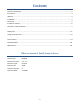
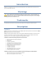
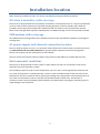
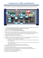
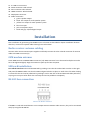
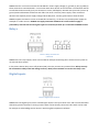
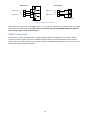
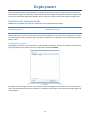
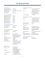
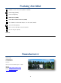
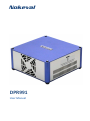
Nokeval DPR991 User Manual Contents Document information ...................................................................................................................................... 2 Introduction ....................................................................................................................................................... 3 Warnings............................................................................................................................................................ 3 Trademarks ........................................................................................................................................................ 3 Description ........................................................................................................................................................ 3 Installation location ........................................................................................................................................... 6 Connectors, LEDs and buttons........................................................................................................................... 7 Installation ......................................................................................................................................................... 8 Deployment ..................................................................................................................................................... 11 Usage and maintenance .................................................................................................................................. 12 Troubleshooting .............................................................................................................................................. 13 Technical data.................................................................................................................................................. 14 Packing checklist .............................................................................................................................................. 16 Manufacturer .................................................................................................................................................. 16 Document information Device Scope: Firmware Versions: DPR991 1.1 - 1.1 Document Type: Document ID: Document Version: Document Date: manual 3500 9 9.10.2012 2 Introduction DPR991 is an integrated in-house control and data acquisition unit for Nokeval radio transmitters and devices with RS-485 connection. Warnings Please read the user manual before installing and using this device. Incorrect installation can damage the device and cause a danger of electric shock. The warranty does not cover damage resulting from incorrect installation or use. Trademarks Any trademarks mentioned in this manual are the property of the respective trademark owners. Description Technical DPR991 is housed in air cooled aluminium case. DPR991 radio receiver operates on the license free 433,92 MHz ISM-band (Industrial, Scientific, Medical). DPR991 is the easy and fast solution, which can be used for building data acquisition or in-house control system by using wireless or wired transmitters. DPR991 replaces an ordinary computer used in data acquisition, but is a more reliable, integrated and energy efficient solution. In addition it includes the following components and connections: Radio transmitter for wireless transmitters GSM modem RS-485 bus connection Two digital inputs and output connections Flash-memory for report database backup HDMI, DisplayPort and DVI connections 4 x USB 2.0 connections 2 x USB 3.0 connections 10M/100M/1Gbps Ethernet-connection Analog and digital audio connections In addition to hardware and connections DPR991 includes the following pre-installed software: Nokeval PromoLog Server data acquisition software Nokeval PromoLog Web Interface software 3 Microsoft Windows 7 Professional operating system Microsoft SQL Server Express 2008 R2 database server Apache HTTP web server software PHP server-side scripting language This manual covers the installation and use of DPR991. PromoLog and PromoLog Web Interface software have their own manuals, which are good to get to know in addition to this manual. Transmitters DPR991 GSM SMS alarms Web based remote access Picture 1. Data acquisition system overview DPR991 in-house control unit includes a radio receiver for wireless transmitter data receiving and a GSM modem, which can send alarms as SMS messages. Several different types of wired and wireless transmitters for different measurement targets can be added to the system. Typical measuring targets are for example food cold storage temperatures. In-house control system’s core is the PromoLog data acquisition software, which is run on the internal computer of in-house control unit. Equipment DPR991 in-house control unit is delivered with the following equipment. Check contents for the following items: 4 1. 2. 3. 4. 5. 6. 7. 8. AC to DC power adapter (100-240V to 12VDC 5A 60 W) AC power cable (IEC-connector) Radio receiver BNC-BNC Coax cable (4,6 meters RG-58) Radio receiver antenna BNC FEMALE TO FEMALE BULKHEAD ADAPTOR Radio receiver antenna installation holder Radio receiver antenna GSM modem antenna DVI-VGA adapter (not seen in picture below) 2 4 1 3 Picture 2. DPR991 equipment 5 6 5 7 Installation location When choosing installation location for the unit, the following things should be considered: Wireless transmitter radio coverage The unit has to be positioned such that wireless transmitters’ transmissions reach it. It has to be positioned as close to the wireless transmitters as possible avoiding proximity of thick or metallic walls. With the included 5 meter long antenna cable and installation holder the antenna can be positioned to achieve better radio coverage. With repeaters FT20-Repeater or FTR960 coverage area can be improved if needed. GSM modem radio coverage Also GSM network coverage affects the installation location in the most difficult conditions at the edge of coverage area. AC power supply and ethernet connection location The unit needs AC power to work, so an AC power outlet needs to be located nearby. In-house control unit is recommended to be used with UPS device to guarantee data acquisition continuity during power failures. See chapter Use and maintenance for more details. The unit can be connected to ethernet network using CAT5 or CAT6 cable (not included with the unit). Environmental conditions The unit has to be positioned so that no water or other liquids can spill over it and where it will not be exposed to excessive humidity or steam. The installation space has to be in room temperature, not over +30 °C. The unit generates some heat too, so it must not be placed in a closed space like a closet or a box. Ventilation holes of the unit must not be blocked. The unit has a system fan that is operating according to the temperature. The fan blows warm air out of the case and takes in cool air from both the ventilation holes of both sides. The location of connectors and the space required by cables should be considered when choosing the mounting space to avoid damage to the connectors. 6 Connectors, LEDs and buttons All the LEDs, buttons and connectors are located in the back panel of the unit as seen in the picture below. The only exception is the SIM card slot of the GSM modem that is located on the right side of the unit. 4 9 11 14 1 2 15 5 3 17 6 7 19 8 10 12 13 17 16 18 20 Picture 3. DPR991 back panel 1. 12 V DC power supply input for the whole unit. Only use the external power supply that came with the unit. Using wrong type of power supply may damage the unit seriously. 2. Relays connector. Only for safety extra low voltage. 3. Digital inputs connector. Only for safety extra low voltage. 4. Radio receiver activity LED. Blinks when it is connected to PromoLog data acquisition program. 5. Radio receiver receiving LED. Blinks when receiving radio packet. If the LED stays lit for a longer period or continuously, the area may have radio interference in the 433.92 MHz frequency band. 6. Radio receiver antenna connector (BNC 50Ω). 7. RS-485 bus LED. Blinks when there is traffic in the bus. 8. RS-485 bus connector and 12V (200 mA) direct current output to supply devises connected to the bus. 9. GSM LED. This LED has 4 states, which indicate the state of the GSM modem: a. When LED is not lit, the modem is not operating. b. When LED blinks every second, the modem is on, but not connected to the network and cannot send any messages. c. When LED blinks more slowly (every 3 seconds), the modem is registered to the network and is ready to send messages. d. When LED is lit and not blinking at all, there is a call going on. 10. SSD (Solid State Disk) LED. Blinks when SSD drive is reading or writing data. 11. Power LED. Is lit when power is on. 12. Power button. Needs to be pressed in case the unit has not started automatically. 13. Reset button. The button is sunk deeper than the surface of the panel to avoid accidental use. 14. GSM modem antenna connector (SMA 50Ω). 15. Ethernet-connector (10/100/1000 Mbps) and LEDs. 16. 2 x USB 3.0 connectors. Blue colored. 7 17. 18. 19. 20. 21. 22. 4 x USB 2.0 connectors. eSATA connector. Red colored. DVI-I connector. Blue colored. HDMI connector. Black colored. DisplayPort connector. Audio connectors: a. green: speaker output b. black: line output for multi speaker system c. yellow: line output for multi speaker system d. blue: line input e. pink: microphone input f. black and grey: S/PDIF-digital output Installation Start installation by positioning the DPR991 unit to a location as described in chapter Installation location. After this, connect all required cables starting from radio cables. Radio receiver antenna cabling Connect radio receiver antenna parts together and finally connect the silver colored connector of antenna cable to the BNC connector (6). GSM modem antenna Screw GSM antenna to DPR991 ANT2 connector (14). SMA connector has to be turned multiple revs and it has to be tightened lightly. Align the antenna to point up for best reception. SIM card installation Turn off the unit first and install the SIM card by pushing it into the slot marked with a sticker in the right side panel of DPR991. Make sure that the SIM card gets locked to its place. A small click is felt when locking is successful. The card can be pulled out by pushing it until a new click is felt and SIM card slides pushed by a spring on its way out after which the card stops and can be pulled out completely. RS-485 bus connection +12V GND D1 D0 Picture 4. RS-485 bus connection If DPR991 is used with wired devices or for example external wireless radio receiver, they can be connected easily by using this RS-485 bus. 8 DPR991 has four connector terminals for RS-485 bus: Power supply voltage (1), ground (2), D1 (3) ja D0 (4). These work when connected with 1:1 connection with other devices in the same bus. Terminals D1 and D0 transfer data bi-directionally (only one direction at a time, half-duplex). Ground wire (terminal 2) evens up ground potential between the devices and offers the return route for power supply. If the connected devices have separate power supply voltage and RS-485 ports, connect ground wire to both of them. DPR991 supplies 12V direct current on RS-485 bus terminal (1), so this bus can provide power supply for example to a radio receiver. DPR991 can supply maximum of 200 mA of current and the supply is protected by internal self-recovering PTC type fuse. Ground (terminal 2) is connected to DPR991 chassis. Relays Picture 5. Relay connector and connection DPR991 has two relay outputs, which can be used for example connecting the in-house control system to an external alarm system. In the picture above relays are at off-position (NO). The relay contacts are potential free. Relays can only be connected to safety extra low voltage circuits (< 48 V). The maximum current for the relays is 5 A. Digital inputs Picture 6. Digital input connector DPR991 has two digital inputs, which suit NPN type outputs. The inputs float at 5 V and are activated when shorted to ground. Therefore a closing contact switch can be directly connected. This switch can be used for example to acknowledge active alarms in PromoLog data acquisition software. 9 NPN sensors Contact input Digital input 2 5 V 3 Digital input 2 5 V 3 GND 2 GND 2 Digital input 1 5 V 1 Digital input 1 5 V 1 Closing contact Picture 7. Digital input connection Digital input 1 is on terminal 1 and digital input 2 on in terminal 3. Ground is on terminal 2 and it is shared between the two digital inputs. Ground is also connected to the chassis of DPR991. Maximum allowed input voltage range is ±30 V for both inputs. Other connectors Connect also a mouse, a keyboard and a suitable display cable to the appropriate connectors. Finally connect the power supply connector to DPR991 power connector and the detachable power cord to a power outlet. The power supply’s green LED should light. If DPR991 network features are to be used, also an Ethernet cable should be connected. 10 Deployment After pressing the power switch Windows 7 Professional operating system and required services will load automatically. Login is also automatic. About 30 seconds after login PromoLog data acquisition program will launch with the default application template and is ready for creating custom data acquisition application. Default users and passwords DPR991 has two default user accounts, which both have administrator privileges. Default user: promolog Password: promolog Administrator user: Administrator Password: dontpanic Administrator user account is reserved for maintenance operations. For normal use, promolog user account is recommended to have automatic login. Password is needed in case Windows remote desktop connection (RDP) is used. Changing the password Changing the password can be done with normal methods in Windows, but after the change, the automatic login stops working and needs to be set on again with command netplwiz. Picture 8. User Accounts management opening with netplwiz command. To enable automatic login with the new password, click promolog user and then tick on ”Users must enter a user name and password to use this computer” and then tick it off again. Then press OK and input login and new password. 11 Connecting to a domain DPR991 can be connected to a domain like any normal Windows 7 Professional computer. However, after the operation, the user has to make sure, that automatic login is enabled with some method. In domain use the user becomes also responsible of automatic backup settings and functionality. Usage and maintenance UPS device DPR991 in-house control unit is meant for constant use, so its power supply is recommended to be protected with a UPS device that is available for purchase separately. The power consumption of DPR991 is moderate compared to an ordinary computer, so UPS devices designed for normal workstation use give over 30 minutes of reserve power. It is also recommended to connect UPS device to DPR991 in a way that UPS shuts operating system down and turns off hardware before battery power runs out. Instructions for this can be found in UPS device’s user manual. Automatic start If DPR991 power supply is interrupted regardless of all precautions, it will restart automatically with few seconds delay after power is back and logs in back to Windows with promolog user account. After this PromoLog data acquisition program starts automatically again. Windows Update and restart If DPR991 is connected to data network, Windows security updates have to be installed unquestionably and regularly, at least once a month. To finish installing updates DPR991 has to be restarted. This can be done when it is most convenient and disrupts use as least as possible. Installing updates and restarting DPR991 occasionally is recommended even without regular connection to data network. Anti-virus software Windows 7 Professional operating system comes with a basic firewall application, but with no anti-virus software. It is highly recommended to install some reliable anti-virus software. Even if DPR991 is not connected to any data networks, a virus or malware program may infect the system for example via connected USB memory. Also because of this, regular installation of Windows updates and anti-virus program’s updates are highly recommended. Warranty will not cover damage or problems caused by virus or malware programs. Installing other programs Installing other 3rd party software to DPR991 is not recommended. 12 Troubleshooting Problem: DPR991 is too wide to fit a narrow but high mounting location. Solution: Turn DPR991 on its side (put the side with no labels down). On application Nokeval will send selfadhesive rubber bumpers that can be attached to this side. Problem: Display is black and is not powering on from the power button. Solution: Some displays have their power button located under or behind the bottom edge of the display and in front right edge of the display there is a power button symbol, easily mistaken as a touch button, is there only to indicate in what vertical position real power button is located under/behind the edge. Problem: Display is black even though DPR991 is powered on. Solution: Check that DPR991 is really on (fan is rotating and PWR LED is lit) and that display cable connectors are inserted all the way and properly tightened from both ends. Problem: DPR991 was shut down during power failure and did not restart automatically after that. Solution: Start DPR991 with the PWR button deep in the back panel. See picture 3 and marker 12. Problem: DPR991 restarted after power failure, but failed to load the operating system. Solution: Remove possible USB memory, to avoid DPR991 trying to load operating system from it. Problem: GSM modem is not working. Solution: Shutdown DPR991 before plugging in or removing the SIM card. Plugging in the SIM card while powered on may damage the SIM card and/or the GSM modem. 13 Technical data Digital inputs, 2 pieces Environment Storage temperature Operating temperature Relative humidity Protection class Case material Connector -20…+50 °C +10…+30 °C 5…90 %RH, non-condensing IP20 aluminum Type External dimensions Height without cables Width without cables Depth without cables Height with cables Width with cables Depth with cables Weight without cables Weight with cables Maximum voltage 95 mm 200 mm 200 m 95 mm 200 mm 210 mm 2.0 kg 3.0 kg Relay outputs, 2 pieces Connector Type Maximum voltage Maximum current External power supply Input voltage range Output voltage Output power Type Display connectors USB connectors Network connector Standard PC, Mini-ITX HDMI, DisplayPort and DVI 4 x USB 2.0, 2 x USB 3.0 10/100/100 Mbps RJ45 Ethernet Audio connectors 5 x 3.5 mm stereo connector RAM 2 GB DDR3 Mass storage memory 40 GB SATA SSD drive Database backup memory 2-4 GB SSD or 4 GB CF 11.5…12.5 VDC Max. 60 W Radio receiver Antenna connector Type Sensitivity Maximum input power Bandwidth Selective filter Compatible devices 50 Ω BNC female License-free 433.92 MHz ERC/REC/70-03 sub band f -3 -100 dBm (BER 3x10 ) +10 dBm 180 kHz Yes, SAW-type Nokeval FT-, FTR- and MTRseries 433.92 MHz radio transmitters and FT20 and FTR960 repeater. Regulatory information EMC immunity EMC emission GSM modem Antenna connector Type Sensitivity Transmitting power SIM card 2 1.5 mm , detachable 4-pin screw post connector closing contact (NO) relay output, potential free, connected to the chassis 48 VDC 5A Computer 100…240 VAC 12 VDC Max. 60 W Internal power supply Input voltage range Output power 2 1.5 mm , detachable 3-pin screw post connector NPN type output, floats in 5 V and activates when grounded, ground is connected to the chassis -30…+30 V 50 Ω SMA female 4 band EGSM 850/900/1800/1900 MHz -107 dBm (850/900) -106 dBm (1800/1900) 2 W (850/950 MHz) 1 W (1800/1900 MHz) 1.8/3V automatic detection 14 EN 61326 EN 61326, class B 15 Packing checklist DPR991 in-house control unit (94520 or 94663) Power supply (94225) Power cord (93525) GSM antenna (95860) Coax cable with BNC connectors (93897) Female BNC to Female BNC adapter, nut and spacer (93233) Antenna holder (93657) Short antenna with BNC connector (91526) DVI-VGA adapter (95931) Packer ID: Manufacturer Nokeval Oy Yrittäjäkatu 12 FI-37100 Nokia Finland Phone +358 3 342 4800 (Mon-Fri 8:3016:00) WWW http://www.nokeval.com/ Email [email protected], [email protected] 16