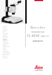
1
Transmittedlight Base
TL BFDF (MDG 29)
User Manual
Contents
Page
Overviews
Safety concept . . . . . . . . . . . . . . . . . . . . . . . . . . . . . . . . . . . . . . . . . . 4
Symbols . . . . . . . . . . . . . . . . . . . . . . . . . . . . . . . . . . . . . . . . . . . . . . . . 5
Safety regulations . . . . . . . . . . . . . . . . . . . . . . . . . . . . . . . . . . . . . . . 6
Controls . . . . . . . . . . . . . . . . . . . . . . . . . . . . . . . . . . . . . . . . . . . . . . . . 8
Assembly
First steps . . . . . . . . . . . . . . . . . . . . . . . . . . . . . . . . . . . . . . . . . . . . . 10
Removing the transport anchors . . . . . . . . . . . . . . . . . . . . . . . . . . 11
Unpacking and assembling the various components . . . . . . . . 12
Operation
Light intensity . . . . . . . . . . . . . . . . . . . . . . . . . . . . . . . . . . . . . . . . . . 14
Transmitted-light control . . . . . . . . . . . . . . . . . . . . . . . . . . . . . . . . 14
IsoPro™ cross-stage . . . . . . . . . . . . . . . . . . . . . . . . . . . . . . . . . . . . 14
Care, maintenance . . . . . . . . . . . . . . . . . . . . . . . . . . . . . . . . . . . . . 15
Expansion diagram . . . . . . . . . . . . . . . . . . . . . . . . . . . . . . . . . . . . . 16
Scope of delivery . . . . . . . . . . . . . . . . . . . . . . . . . . . . . . . . . . . . . . . 17
Dimensions . . . . . . . . . . . . . . . . . . . . . . . . . . . . . . . . . . . . . . . . . . . . 18
Technical data . . . . . . . . . . . . . . . . . . . . . . . . . . . . . . . . . . . . . . . . . 19
TL BFDF transmitted-light base – Contents
Dear User
Thank you very much for your trust in Leica Microsystems.
We hope you will enjoy working with our high-quality, efficient
products, and wish you much success.
In developing our instruments, we put much emphasis on a
simple, self-explanatory operation. However, take your time to
read the user manual, in order to familiarize yourself with your
stereomicroscope for optimal use of all its benefits and options.
Should you have any questions, please consult your local Leica
representative. You will find the address of the closest local
representative, as well as valuable information about products
and services from Leica Microsystems on our homepage at
www.leica-microsystems.com
We are gladly at your service. CUSTOMER SERVICE is a big
thing with us. Not only before the sale, but afterwards as well.
The user manual
This user manual is available in 20 additional languages on our
interactive CD-ROM.
User manuals and updates are also available for download on
our homepage at www.leica-microsystems.com.
The user manual at hand describes safety instructions, assembly, and handling of the TL BFDF transmitted-light base.
TL BFDF transmitted-light base – Contents
Safety concept
1.1 The user manual
The TL BFDF transmitted-light base comes with
an interactive CD-ROM containing all relevant
instructions in 20 additional languages. Keep this
CD-ROM in a safe place, where it is available to
the user. User manuals and updates are also available for download and printout on our homepage at
www.stereomicroscopy.com.
The TL BFDF transmitted-light base is a module
in the Leica M stereomicroscope series. This
user manual describes the special functions of
the transmitted-light base and contains important
instructions for operating safety, maintenance and
the accessory parts.
Before assembly, start up and use, please
read the user manuals mentioned above.
In particular, please observe all safety
instructions.
To maintain the unit in its original condition and
to ensure safe operation, the user must follow the
instructions and warnings contained in these user
manuals.
The M2-105-0 user manual for the Leica M stereomicroscopes contains additional safety rules for
the stereomicroscope, accessories and electrical
accessories, as well as instructions for maintenance.
TL BFDF transmitted-light base – Safety concept
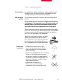
1.1.1 Symbols used
Warning of danger
This symbol indicates information, which
must be read and obeyed. Disregarding these
instructions
– can cause personal harm!
– can lead to malfunction and damage to
instruments.
Warning of dangerous electrical voltage
This symbol indicates information, which
must be read and obeyed.
Disregarding these instructions
– can cause personal harm!
– can lead to malfunction and damage to
instruments.
Important information
This symbol indicates additional information or explanations that intend to provide clarity.
Action
EThis symbol within the text indicates that
certain actions must be carried out.
Explanatory notes
• This symbol indicates additional notes and
explanations provided in the text.
Figures
(1.5) Numbers in brackets within the descriptions
relate to the figures and the items within those
figures. Example (1.3): Figure 1 is located, for
example, on Page 8, and item 3 is the adjustment
button for the light intensity.
Warning - hot surface
This symbol warns against touching hot
surfaces, e.g. those of light bulbs.
TL BFDF transmitted-light base – Safety concept
1.2 Safety regulations
Description
The TL BFDF transmitted-light base fulfills the
highest requirements for observation and documentation of the Leica M-series stereomicroscopes. It contains a path-folding mirror, a device
for partial pupil illumination and relief contrast
generation, a ground-glass screen, an additional
condenser and Fresnel lenses. The complete
stand consists of:
– TL BFDF transmitted-light base
– Column 300 mm or 500 mm long with focusing
drive, manual coarse/fine or motorized focus
– Glass stage plate, clear, 220×170×4mm
– external cold light source of your choice
Accessories:
– Gliding stage
– Leica MATS Thermocontrol System with
heating stage
– Polarization set
and many more (see Expansion diagram)
Intended uses
Units or accessories described in the user manual
have been checked for safety and possible dangers. For any changes to the instrument, modifications or combinations with non-Leica components
that exceed the scope of this manual, consult the
appropriate Leica office or the Leica headquarters
in Wetzlar!
Unauthorized changes of the unit or improper use
renders the warranty null and void.
Place of use
– Only use the TL BFDF transmitted-light base
in closed, dust free rooms and between +10°C
and +40°C. Make sure that the rooms are free
of oil vapors or other chemical vapors, and extreme humidity.
– Set up the electrical components at least 10cm
from walls and combustible objects.
– Avoid large deviations in temperature, direct
sunlight and shocks. This can cause faulty
measurements or microphotographs.
– In warm, or warm and humid climates, the
TL BFDF transmitted-light base requires special
care to prevent formation of fungus.
The TL BFDF transmitted-light base is used for assembling Leica M series stereomicroscopes with
column and microscope carrier.
Prohibited uses
Using the transmitted-light base TL BFDF, its components, and accessories in a way contrary to this
user manual, can lead to bodily harm and damage
to objects. Never:
– change, rebuild or take apart parts, if not specifically instructed to in this manual.
– allow non-authorized persons to open parts of
the instrument.
– use the TL BFDF transmitted-light base for examination and surgery of the human eye.
TL BFDF transmitted-light base – Safety concept
Operator responsibilities
Integration in third-party products
Make sure that
– only authorized and trained personnel is
allowed to operate, maintain and repair the
TL BFDF transmitted-light base and its accessories.
– all operators have read, understood and observe this user manual, and particularly the
safety instructions.
The following must be observed if Leica products
are built into third-party products: The manufacturer of the complete system or the person putting
it on the market is responsible for adhering to
applicable safety regulations, laws and guidelines.
Repairs, Service
– Only Leica Microsystems trained service
personnel or authorized technicians of your
company should repair the equipment.
– Only use original Leica Microsystems parts.
– Before opening the devices, turn off the power
and unplug the main power cables.
Disposal
The products described here must be disposed off
in accordance with applicable local environmental laws and regulations.
Legal requirements
Adhere to general and local regulations relating
to accident prevention and environmental protection.
EC declaration of conformity
Avoid contact with powered electrical
circuits which can lead to injury.
Transport
The TL BFDF transmitted-light base and the accessories have been constructed according to the
state of the art and issued with an EC declaration
of conformity.
– Use the original packaging for shipping or
transporting the TL BFDF transmitted-light base
and the accessory components.
– To prevent damage by vibrations, remove and
separately pack all the moving components
which you have installed yourself (as outlined
in the User Manual) and install the transport
anchors.
TL BFDF transmitted-light base – Safety concept
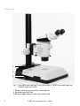
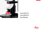
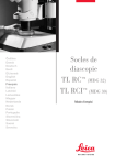
Controls
1
2
3
Fig. 1 L eica MZ16 with ErgoTube™, coarse/ fine drive, TL BFDF transmitted-light base,
standard stage and 4×slides
1 Adapter plate for easy assembly of focusing drives
2 Standard stage 10 447 269
3 Button to toggle between bright field and dark field
TL BFDF transmitted-light base – Controls
Fig. 2 TL BFDF transmitted-light base adapter
plate
Fig. 3 Adapter at the focusing drive
1
Fig. 4 Button to toggle between bright field/ dark
field (here: Button in dark field position)
Fig. 5 Rear side of TL BFDF transmitted-light base
1Connector for cold light sources (light conductor active f = 10mm, end tube f = 13mm)
TL BFDF transmitted-light base – Controls
Important information
before first use
Unpacking the Leica BFDF transmitted-light base
• Unpack the base on an adequately sized, level
and nonskid underlay.
• Read and understand the User Manual included
with this transmitted-light base.
10
TL BFDF transmitted-light base – Unpacking
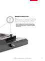
Removing the transport anchors
Before you can use the transmitted-light base
for the first time, it is absolutely necessary to
remove the two transport anchors as follows:
• from the rear side of the transmitted-light
base - remove anchor of the switching slide
• from the top of the base - remove the anchor
of the mirror
TL BFDF transmitted-light base – Transport anchors
11
Assembly
Before unpacking, make sure no
persons can be injured by falling
or tilting parts.
3.1 Unpacking the base
The base is delivered with the adapter plate
attached. The selected stage (IsoPro™ crossstage or standard stage 10 447 269), and the
focusing drive will have to be mounted later.
Make sure the devices are unpacked on a flat,
sufficiently dimensioned, and non-slip surface.
3.2.2 IsoPro™ cross-stage
Before the IsoPro™ cross-stage is mounted to the
base, the axis containing the control buttons is
attached either on the left or the right side of the
cross-stage.
If the controls shall be mounted on the left hand
side, the gear rod on the bottom side of the crossstage must be unscrewed and re-attached in
reverse.
ETake the glass plate from the cross-stage.
ETurn the cross-stage around and place it onto
a non-slip surface.
3.2 Stage assembly
The TL BFDF transmitted-light base can be
equipped with two different stages. The selected
stage is mounted on the base before startup. The
two stages can be easily exchanged at any time.
EChange the gear rod (6.2) from the left to the
right hand side.
ESkip the next two steps to mount the controls.
Control assembly
The following paragraph assumes the base without the stage mounted. Disassembly is performed
in reverse order of the following steps.
ETake the glass plate from the cross-stage.
ETurn the cross-stage around and place it onto
3.2.1 Standard stage
the desired side. The fastener snaps into the
cross-stage magnetically.
EAttach the axis with the two supplied Allen
screws.
EAttach the cover rail to the cross-stage.
ETake the glass plate from the rectangular gap in
the standard stage.
EPosition the stage on the transmitted-light base
in such way that the four holes align over those
in the base.
EAttach the stage to the base with the four
supplied Allen screws.
ERe-insert the glass plate back into the standard
stage.
12
a non-slip surface.
EAttach the axis with the control buttons (6.1) to
Cross-stage assembly
EPlace the cross-stage onto the base.
EPull the upper part of the cross-stage carefully
toward the user, fixing the lower part onto the
transmitted-light base.
EAttach the cross-stage evenly to the three
threaded holes.
EPush the cross-stage all the way back to the
fence in direction of column.
ERe-insert the glass plate back into the standard
stage.
TL BFDF transmitted-light base – Assembly
3.3 Focusing drive > column
EUnscrew the adapter plate (1.1) from the base
using the supplied Allen key.
EAttach your focusing drive column to the bottom
with the three Allen screws (2).
ERe-attach the adapter plate to its original
position with the three Allen screws.
1
2
3.4 Intermediate adapter assembly
The distance between focusing and optical axis is
larger on the new TL BFDF transmitted-light base.
To balance this, mount the supplied adapter between column and microscope carrier.
EAttach the adapter (3) to the focusing drive for
the pins to lock in recess.
EAttach the adapter using the supplied Allen key.
Fig 6 Rear side of IsoPro™ cross-stage
1 Axis with controls
2 Gear rack, mounted to cross-stage
3.5 Equipment assembly
Once the adapter is mounted to the focusing drive
the microscope carrier, optics carrier and
the entire equipment can be assembled as usual.
3.6 Connecting the cold light-source to
the TL BFDF transmitted-light base
EPush the appropriate end of the cold light guide
into the rear side of the base.
EFor further information about the use of cold
light sources refer to the instructions supplied
separately.
1
2
Fig. 7 Cross-stage controls
1 Control button for x-direction movement
2 Control button for y-direction movement
TL BFDF transmitted-light base – Assembly
13
Operation
4.1 Light intensity control
4.3 Operating the cross-stage IsoPro™
Please observe the user manual and in
particular the safety regulations of the
manufacturers of the light guide and cold light
source.
ETo move the stage in X direction rotate the
outer knob (7.1)
ETo move the stage in Y direction rotate the
inner control ring (7.2)
ETurn on the cold light source according to the
manufacturer's user manual and connect,
activate, and adjust the light intensity.
4.2 Transmitted-light control
The TL BFDF transmitted-light base has a potentiometer that switches the light from "bright field" to
"dark field".
4.2.1 Bright field
Bright field is suited for transparent objects with
structures that are rich in contrast. The object is
illuminated directly from the bottom to appear pin
sharp and in natural colors on a bright surface.
ETurn the control button to limit "BF"
("bright field").
4.2.2 Dark field
Ring illumination is used for dark field illumination,
so that no direct light reaches the objective without an object. Only the structure of semi-transparent, opaque objects, like foraminifera or fish
eggs, disperse the light, making the object visible
against a dark surface.
ETurn the control button to limit "DF" ("dark field").
14
TL BFDF transmitted-light base – Operation
Care, maintenance
In this chapter
we would like to explain and help you understand the careful
handling of your valuable instrument, and provide you with
some tips for proper maintenance and cleaning.
We guarantee
quality
You are using a precision instrument with many performance
features.
As appropriate for such instruments we guarantee the quality
of our products. This guarantee covers all manufacturing and
material defects of the original equipment, but not any damages that are the result of inappropriate use or negligence.
Please handle your valuable optical instrument with the appropriate care. If you do so you will be able to enjoy many decades
of accurate service by this equipment without any deterioration. This is the reputation of our equipment.
Should your equipment, however, no longer
provide accurate service, please contact
your authorized service representative, your
Leica distributor or directly Leica Microsystems (Switzerland) Ltd., CH-9435 Heerbrugg.
Protect your
instruments
• Protect from moisture, fumes, acids,
bases and corrosive materials. Do not
store any chemicals in close proximity
of the instrument.
• Protect from inappropriate use or handling.
Never use off-brand electrical connectors or wires; never disassemble optical
systems or mechanical components, if no
particular reference is made to that purpose in the instructions.
• Protect from oil and grease.
Slide surfaces and mechanical
components shall never be lubricated.
TL BFDF transmitted-light base – Care, maintenance
15
Expansion diagram
10 445 615 (300mm)
10 446 100 (500mm)
10 447 392
11 101 784
10 447 391
10 446 303
10 447 276
10 447 106 (300mm)
10 447 185 (500mm)
10 446 304
10 447 275
10 446 228
10 446 301
10 447 269
10 446 176 (300mm)
10 447 041 (500mm)
10 446 353
10 446 302
10 382 130
10 361 719
10 447 368
10 446 352
10 447 390
10 446 351
10 446 350
10 447 393
10 447 394
10 447 395
10 447 342
10 446 340
10 447 400
10 446 341
10 447 398
10 447 431
16
TL BFDF transmitted-light base – Expansion diagram
M1-218-4 / 11.05
10 447 443
Scope of delivery
Incident-light bases
10 446 340 Incident-light base for S series
10 446 341 Sub-base for transmitted-light for
S series incident light base
10 447 342 Incident-light base for M series
10 446 350 TL ST transmitted-light base
10 446 351 TL BFDF transmitted-light base
10 447 390 TL RC™ transmitted-light base for
external cold light sources
10 446 352 TL RCI™ transmitted-light base with
integrated halogen illumination
Stages
10 447 269Standard stage for TL BFDF, TL RC™
and TL RCI™ transmitted-light bases
10 446 353Cross-stage for TL BFDF, TL RC™,
TL RCI™ transmitted-light bases and
incident-light base (with adapter
10 447 368)
10 447 368Adapter between cross-stage and
10 447 342 incident light base
10 447 275
10 447 276
10 447 391
10 447 392
Thermo stage Leica MATS TL with
controller
Adapter for stages with ∅120mm
Stage for LifeOnStage accessory
Universal carrier for Petri dish,
slides (up to four pieces) etc.
11 101 784
Column adapter for micromanipulation
10 446 301 Sliding stage, ∅120mm
10 446 302 Polarization stage, ∅120mm
10 382 130 Object guide for polarization stage
10 361 719Compensator Red I for Pol rotating
stage
10 446 303 Cup stage, ∅120mm
10 446 304 Universal carrier, ∅120mm
10 446 228 Glass insert with Pol, ∅120mm
Focusing drives
10 445 615Focusing drive with profile 300mm
column for incident and transmittedlight bases
10 446 100Focusing drive with profile 500mm
column for incident and transmittedlight bases
10 447 106Focusing drive, coarse/fine, with
300mm profile column for incident
and transmitted-light bases
10 447 185Focusing drive, coarse/fine, with
500mm profile column for incident
and transmitted-light bases
10 446 176Motorized focus drive with 300mm
column and power supply for incident and transmitted-light bases
10 447 041Motorized focus drive with 500mm
column and power supply for incident and transmitted-light bases
Filter
10 447 400 Day light filter for TL ST base
10 447 394Fluorescence filter BG38 for transmitted-light bases TL RC™/ RCI™
10 447 395 UV filter for bases TL RC™/ RCI™
10 447 393 Filter ND (gray filter) for bases
TL RC™/ RCI™
Illumination
10 447 443Leica USB mouse, five key mouse,
freely assignable for connections
to transmitted-light bases TL RCI™
or PC
10 443 401USB cable to connect TL RCI™ base
to a PC
10 447 398 Foot switch with CAN bus connector
10 447 431
Ergonomic Accessories
Leica ErgoRest (palm rest for
fatigue-free operation)
TL BFDF transmitted-light base – Expansion diagram
17
Dimensions transmitted-light base
Dimensions in mm
370
154
390
90
116
154
340
18
TL BFDF transmitted-light base – Dimensions
MZ-16
Base
Technical data
Leica TL BFDF
Light source external via cold light source
Illuminated area 40mm
Connections
Connection for cold light conductor, active f=10mm, end tube f=13mm
Weight
5.8 kg
Illumination types
Bright field
yes
Dark field
yes
Oblique light
no
Relief Contrast System (RC™)
no
CCIC
no
(Constant Color Intensity Control)
Internal shutter/Lamp control yes*
Integrated filter holder
no
Coated optic to no
Raise of color temperature
Matching of high num. aperture
yes**
Remote control possibility
yes***
AntiShock™ Pads
yes
Size of the base (W×H×D, in mm)340×390×90
*with cold light source Leica CLS150 LS **concave mirror *** with external light source
TL BFDF transmitted-light base – Technical data
19
Leica Microsystems – the brand
for outstanding products
Leica, the leading brand for microscopes and scientific instruments, developed
from five brand names, all with a long tradition: Wild, Leitz, Reichert, Jung and
Cambridge Instruments. Yet Leica symbolizes innovation as well as tradition.
Leica Microsystems – an international company
with a strong network of customer services.
Australia:
Gladesville
Austria:
Vienna
Canada:
Richmond Hill/Ontario
Denmark:
Herlev
France:
Rueil-Malmaison
Germany:
Bensheim
Italy:
Milan
Japan:
Tokyo
Korea:
Seoul
Netherlands:
Rijswijk
People’s Rep. of China:Hong Kong
Portugal:
Lisbon
Singapore
Spain:
Barcelona
Sweden:
Sollentuna
Switzerland:
Glattbrugg
United Kingdom:
Milton Keynes
USA:
Bannockburn/lllinois
Tel. +61 2 9879 9700
Tel. +43 1 486 80 50 0
Tel. +1 905 762 2000
Tel. +45 4454 0101
Tel. +33 1 47 32 85 85
Tel. +49 6251 136 0
Tel. +39 0257 486.1
Tel. + 81 3 5421 2800
Tel. +82 2 514 65 43
Tel. +31 70 4132 100
Tel. +852 2564 6699
Tel. +351 21 388 9112
Tel. +65 6779 7823
Tel. +34 93 494 95 30
Tel. +46 8 625 45 45
Tel. +41 44 809 34 34
Tel. +44 1908 246 246
Tel. +1 847 405 0123
Fax +61 2 9817 8358
Fax +43 1 486 80 50 30
Fax +1 905 762 8937
Fax +45 4454 0111
Fax +33 1 47 32 85 86
Fax +49 6251 136 155
Fax +39 0257 40 3475
Fax +81 3 5421 2896
Fax +82 2 514 65 48
Fax +31 70 4132 109
Fax +852 2564 4163
Fax +351 21 385 4668
Fax +65 6773 0628
Fax +34 93 494 95 32
Fax +46 8 625 45 10
Fax +41 44 809 34 44
Fax +44 1908 609 992
Fax +1 847 405 0164
and representatives of Leica Microsystems
in more than 100 countries.
In accordance with the ISO 9001 certificate, Leica Microsystems (Switzerland) Ltd, Business
Unit Stereo & Macroscope Systems has at its disposal a management system that meets the requirements of the international standard for quality management. In addition, production meets
the requirements of the international standard ISO 14001 for environmental management.
www.leica-microsystems.com
The companies of the Leica Microsystems Group operate internationally in three business segments, where
we rank with the market leaders.
• Microscopy Systems
Our expertise in microscopy is the
basis for all our solutions for visualization, measurement and analysis of
micro-structures in life sciences and
industry. With confocal laser technology and image analysis systems, we
provide three-dimensional viewing
facilities and offer new solutions for
cytogenetics, pathology and materials sciences.
• Specimen Preparation
We provide comprehensive systems
and services for clinical histo- and
cytopathology applications, biomedical research and industrial
quality assurance. Our product range
includes instruments, systems and
consumables for tissue infiltration
and embedding, microtomes and cryostats as well as automated stainers
and coverslippers.
• Medical Equipment
Innovative technologies in our surgical microscopes offer new therapeutic approaches in microsurgery.
Illustrations, descriptions and technical data are non-binding – subject to change without notice.
M2-218-1en • © Leica Microsystems (Switzerland) Ltd • CH-9435 Heerbrugg, 2005 – en – VI.2007
Leica Microsystems’ mission is to be the world’s first-choice provider of innovative solutions to our customers’ needs for vision, measurement and analysis of
micro-structures.