1
Reference: VMLAB-UPM-TR1
Date: 15/09/2009
Issue: 1.5
Page: 1 of 85
ESTEC/Contract No. 21392/08/NL/JK
Guidelines for integrating device drivers
in the ASSERT Virtual Machine
Output of WP 300
Written by:
Juan Zamorano, Jorge López, Juan A. de la Puente
Revised by:
Juan A. de la Puente
Tullio Vardanega
Accepted by:
Maxime Perrotin
Organization
UPM
Organization
UPM
UPD
Organization
ESTEC
Date
15/09/2009
Date
15/09/2009
15/09/2009
Date
22/09/2009
Reference: VMLAB-UPM-TR1
Date: 15/09/2009
Issue: 1.5
Document Change Record
Issue/Revision
1.0
1.1
1.2
1.3
1.4
1.5
VMlab-UPM-TR1
Date
22/12/2008
15/01/2009
06/05/2009
24/07/2009
29/07/2009
15/09/2009
Change
First version for review
Revised as per review comments
Minor changes in section 2
Draft version for final review
Revised version for final review
Final version for acceptance review
Author
J. Zamorano, J, López
J. Zamorano, J, López
J. Zamorano, J, López
J.A. de la Puente, J. Zamorano
J.A. de la Puente, J. Zamorano
J.A. de la Puente, J. Zamorano
Last Modified on: September 23, 2009
page 2 of 85
Reference: VMLAB-UPM-TR1
Date: 15/09/2009
Issue: 1.5
Abstract
This document contains a set of guidelines for extending the ASSERT Virtual Machine kernel with device drivers.
The real-time kernel is a version of ORK+, the Open Ravenscar real-time Kernel, which supports the Ada Ravenscar profile as defined in the current Ada 2005 standard. It is integrated with the GNATforLEON compilation
system, and provides full support for the Ada Ravenscar subset, including low-level and system programming
facilities. The document shows how to develop device drivers in Ada using such facilities. The guidelines are illustrated with the development of a communications driver for a SpaceWire device which is part of the GR-RASTA
LEON2 computer board.
VMlab-UPM-TR1
Last Modified on: September 23, 2009
page 3 of 85
Reference: VMLAB-UPM-TR1
Date: 15/09/2009
Issue: 1.5
VMlab-UPM-TR1
Last Modified on: September 23, 2009
page 4 of 85
Reference: VMLAB-UPM-TR1
Date: 15/09/2009
Issue: 1.5
Contents
1
2
3
Introduction
1.1 Purpose . . . . . . . . . . . . . . .
1.2 Scope . . . . . . . . . . . . . . . .
1.3 Glossary . . . . . . . . . . . . . . .
1.3.1 Acronyms and abbreviations
1.4 Applicable and reference documents
1.4.1 Applicable documents . . .
1.4.2 Reference documents . . . .
1.4.3 Standards . . . . . . . . . .
1.4.4 Other documents . . . . . .
1.5 Overview . . . . . . . . . . . . . .
.
.
.
.
.
.
.
.
.
.
.
.
.
.
.
.
.
.
.
.
.
.
.
.
.
.
.
.
.
.
.
.
.
.
.
.
.
.
.
.
.
.
.
.
.
.
.
.
.
.
.
.
.
.
.
.
.
.
.
.
.
.
.
.
.
.
.
.
.
.
.
.
.
.
.
.
.
.
.
.
.
.
.
.
.
.
.
.
.
.
.
.
.
.
.
.
.
.
.
.
.
.
.
.
.
.
.
.
.
.
.
.
.
.
.
.
.
.
.
.
.
.
.
.
.
.
.
.
.
.
.
.
.
.
.
.
.
.
.
.
.
.
.
.
.
.
.
.
.
.
.
.
.
.
.
.
.
.
.
.
.
.
.
.
.
.
.
.
.
.
.
.
.
.
.
.
.
.
.
.
.
.
.
.
.
.
.
.
.
.
.
.
.
.
.
.
.
.
.
.
.
.
.
.
.
.
.
.
.
.
.
.
.
.
.
.
.
.
.
.
.
.
.
.
.
.
.
.
.
.
.
.
.
.
.
.
.
.
.
.
.
.
.
.
.
.
.
.
.
.
.
.
.
.
.
.
.
.
.
.
7
7
8
8
8
9
9
9
9
10
10
Driver architecture
2.1 I/O subsystem . . . . . . . . . . . . . . . . . . . .
2.1.1 I/O modules . . . . . . . . . . . . . . . . .
2.1.2 I/O operations . . . . . . . . . . . . . . . .
2.1.3 DMA I/O operations . . . . . . . . . . . .
2.2 Device interface . . . . . . . . . . . . . . . . . . .
2.2.1 Bus architecture . . . . . . . . . . . . . .
2.2.2 Bus hierarchy . . . . . . . . . . . . . . . .
2.2.3 Bus hierarchy in the GR-RASTA system .
2.3 Software architecture for device drivers . . . . . .
2.4 Bus configuration . . . . . . . . . . . . . . . . . .
2.5 Integrating drivers in the ASSERT Virtual Machine
.
.
.
.
.
.
.
.
.
.
.
.
.
.
.
.
.
.
.
.
.
.
.
.
.
.
.
.
.
.
.
.
.
.
.
.
.
.
.
.
.
.
.
.
.
.
.
.
.
.
.
.
.
.
.
.
.
.
.
.
.
.
.
.
.
.
.
.
.
.
.
.
.
.
.
.
.
.
.
.
.
.
.
.
.
.
.
.
.
.
.
.
.
.
.
.
.
.
.
.
.
.
.
.
.
.
.
.
.
.
.
.
.
.
.
.
.
.
.
.
.
.
.
.
.
.
.
.
.
.
.
.
.
.
.
.
.
.
.
.
.
.
.
.
.
.
.
.
.
.
.
.
.
.
.
.
.
.
.
.
.
.
.
.
.
.
.
.
.
.
.
.
.
.
.
.
.
.
.
.
.
.
.
.
.
.
.
.
.
.
.
.
.
.
.
.
.
.
.
.
.
.
.
.
.
.
.
.
.
.
.
.
.
.
.
.
.
.
.
.
.
.
.
.
.
.
.
.
.
.
.
.
.
.
.
.
.
.
.
.
.
.
.
.
.
.
.
.
.
.
.
.
.
.
.
.
.
.
.
.
.
.
.
.
.
.
.
.
.
.
.
.
.
.
.
13
13
13
14
14
15
15
15
18
20
21
21
Device register management
3.1 Device register definition
3.1.1 Internal codes . .
3.1.2 Register layout .
3.2 Device registers mapping
3.3 Device registers access .
3.3.1 Mirror objects . .
3.3.2 Shared addresses
3.4 Example . . . . . . . . .
.
.
.
.
.
.
.
.
.
.
.
.
.
.
.
.
.
.
.
.
.
.
.
.
.
.
.
.
.
.
.
.
.
.
.
.
.
.
.
.
.
.
.
.
.
.
.
.
.
.
.
.
.
.
.
.
.
.
.
.
.
.
.
.
.
.
.
.
.
.
.
.
.
.
.
.
.
.
.
.
.
.
.
.
.
.
.
.
.
.
.
.
.
.
.
.
.
.
.
.
.
.
.
.
.
.
.
.
.
.
.
.
.
.
.
.
.
.
.
.
.
.
.
.
.
.
.
.
.
.
.
.
.
.
.
.
.
.
.
.
.
.
.
.
.
.
.
.
.
.
.
.
.
.
.
.
.
.
.
.
.
.
.
.
.
.
.
.
.
.
.
.
.
.
.
.
.
.
.
.
.
.
.
.
.
.
.
.
.
.
.
.
.
.
.
.
.
.
.
.
23
23
23
24
26
27
27
27
28
VMlab-UPM-TR1
.
.
.
.
.
.
.
.
.
.
.
.
.
.
.
.
.
.
.
.
.
.
.
.
.
.
.
.
.
.
.
.
.
.
.
.
.
.
.
.
.
.
.
.
.
.
.
.
.
.
.
.
.
.
.
.
.
.
.
.
.
.
.
.
.
.
.
.
.
.
.
.
.
.
.
.
.
.
.
.
.
.
.
.
.
.
.
.
.
.
.
.
.
.
.
.
.
.
.
.
.
.
.
.
.
.
.
.
.
.
.
.
.
.
.
.
.
.
.
.
.
.
.
.
.
.
.
.
.
.
.
.
.
.
.
.
.
.
.
.
.
.
.
.
.
.
.
.
.
.
.
.
.
.
.
.
.
.
.
.
.
.
.
.
.
.
.
.
.
.
.
.
.
.
.
.
.
.
.
.
.
.
Last Modified on: September 23, 2009
page 5 of 85
Reference: VMLAB-UPM-TR1
Date: 15/09/2009
Issue: 1.5
4
5
6
Interrupt handling
4.1 Interrupt support in the ORK+ kernel .
4.1.1 Implementation details . . . .
4.2 Interrupt names . . . . . . . . . . . .
4.3 Priority ceiling . . . . . . . . . . . .
4.4 Interrupt handlers . . . . . . . . . . .
.
.
.
.
.
.
.
.
.
.
.
.
.
.
.
.
.
.
.
.
.
.
.
.
.
.
.
.
.
.
.
.
.
.
.
.
.
.
.
.
.
.
.
.
.
.
.
.
.
.
.
.
.
.
.
.
.
.
.
.
.
.
.
.
.
.
.
.
.
.
.
.
.
.
.
.
.
.
.
.
.
.
.
.
.
.
.
.
.
.
.
.
.
.
.
.
.
.
.
.
.
.
.
.
.
.
.
.
.
.
.
.
.
.
.
.
.
.
.
.
.
.
.
.
.
.
.
.
.
.
.
.
.
.
.
.
.
.
.
.
.
.
.
.
.
.
.
.
.
.
.
.
.
.
.
.
.
.
.
.
33
34
35
36
38
38
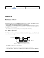
Sample driver
5.1 GRSPW Spacewire . . . . . . .
5.1.1 Link interface . . . . . .
Transmitter . . . . . . .
Receiver . . . . . . . .
5.1.2 Receiver DMA engine .
Receive descriptor table
Status bits . . . . . . . .
5.1.3 Transmitter DMA engine
Transmit descriptor table
5.1.4 RMAP . . . . . . . . .
5.1.5 AMBA interface . . . .
5.2 Driver architecture . . . . . . .
5.2.1 SpaceWire driver . . . .
5.2.2 RastaBoard . . . . . . .
5.2.3 PCI driver . . . . . . . .
5.2.4 AMBA driver . . . . . .
5.3 Source code . . . . . . . . . . .
5.3.1 SpaceWire . . . . . . .
SpaceWire.Parameters .
SpaceWire.HLInterface .
SpaceWire.Registers . .
SpaceWire.Core . . . .
5.3.2 RastaBoard . . . . . . .
5.3.3 RastaBoard.Registers . .
5.3.4 RastaBoard.Handler . .
5.3.5 PCI . . . . . . . . . . .
PCI.Registers . . . . . .
5.3.6 AMBA . . . . . . . . .
.
.
.
.
.
.
.
.
.
.
.
.
.
.
.
.
.
.
.
.
.
.
.
.
.
.
.
.
.
.
.
.
.
.
.
.
.
.
.
.
.
.
.
.
.
.
.
.
.
.
.
.
.
.
.
.
.
.
.
.
.
.
.
.
.
.
.
.
.
.
.
.
.
.
.
.
.
.
.
.
.
.
.
.
.
.
.
.
.
.
.
.
.
.
.
.
.
.
.
.
.
.
.
.
.
.
.
.
.
.
.
.
.
.
.
.
.
.
.
.
.
.
.
.
.
.
.
.
.
.
.
.
.
.
.
.
.
.
.
.
.
.
.
.
.
.
.
.
.
.
.
.
.
.
.
.
.
.
.
.
.
.
.
.
.
.
.
.
.
.
.
.
.
.
.
.
.
.
.
.
.
.
.
.
.
.
.
.
.
.
.
.
.
.
.
.
.
.
.
.
.
.
.
.
.
.
.
.
.
.
.
.
.
.
.
.
.
.
.
.
.
.
.
.
.
.
.
.
.
.
.
.
.
.
.
.
.
.
.
.
.
.
.
.
.
.
.
.
.
.
.
.
.
.
.
.
.
.
.
.
.
.
.
.
.
.
.
.
.
.
.
.
.
.
.
.
.
.
.
.
.
.
.
.
.
.
.
.
.
.
.
.
.
.
.
.
.
.
.
.
.
.
.
.
.
.
.
.
.
.
.
.
.
.
.
.
.
.
.
.
.
.
.
.
.
.
.
.
.
.
.
.
.
.
.
.
.
.
.
.
.
.
.
.
.
.
.
.
.
.
.
.
.
.
.
.
.
.
.
.
.
.
.
.
.
.
.
.
.
.
.
.
.
.
.
.
.
.
.
.
.
.
.
.
.
.
.
.
.
.
.
.
.
.
.
.
.
.
.
.
.
.
.
.
.
.
.
.
.
.
.
.
.
.
.
.
.
.
.
.
.
.
.
.
.
.
.
.
.
.
.
.
.
.
.
.
.
.
.
.
.
.
.
.
.
.
.
.
.
.
.
.
.
.
.
.
.
.
.
.
.
.
.
.
.
.
.
.
.
.
.
.
.
.
.
.
.
.
.
.
.
.
.
.
.
.
.
.
.
.
.
.
.
.
.
.
.
.
.
.
.
.
.
.
.
.
.
.
.
.
.
.
.
.
.
.
.
.
.
.
.
.
.
.
.
.
.
.
.
.
.
.
.
.
.
.
.
.
.
.
.
.
.
.
.
.
.
.
.
.
.
.
.
.
.
.
.
.
.
.
.
.
.
.
.
.
.
.
.
.
.
.
.
.
.
.
.
.
.
.
.
.
.
.
.
.
.
.
.
.
.
.
.
.
.
.
.
.
.
.
.
.
.
.
.
.
.
.
.
.
.
.
.
.
.
.
.
.
.
.
.
.
.
.
.
.
.
.
.
.
.
.
.
.
.
.
.
.
.
.
.
.
.
.
.
.
.
.
.
.
.
.
.
.
.
.
.
.
.
.
.
.
.
.
.
.
.
.
.
.
.
.
.
.
.
.
.
.
.
.
.
.
.
.
.
.
.
.
.
.
.
.
.
.
.
.
.
.
.
.
.
.
.
.
.
.
.
.
.
.
.
.
.
.
.
.
.
.
.
.
.
.
.
.
.
.
.
.
.
.
.
.
.
.
.
.
.
.
.
.
.
.
.
.
.
.
.
.
.
.
.
.
.
.
.
.
.
.
.
.
.
.
.
.
.
.
.
.
.
.
.
.
.
.
.
.
.
.
.
.
.
.
.
.
.
.
.
.
.
.
.
.
.
.
.
.
.
.
.
.
.
.
.
.
.
.
.
.
.
.
.
.
.
.
.
.
.
.
.
.
.
.
.
.
.
.
.
.
.
.
.
.
.
.
.
.
.
.
.
.
.
.
.
.
.
.
.
.
.
.
.
.
.
.
.
.
.
.
.
.
.
.
.
.
.
.
.
.
.
.
.
.
.
.
.
.
.
.
.
.
.
.
.
.
.
.
.
.
.
.
.
.
.
.
.
.
41
41
42
42
43
43
43
45
45
45
45
47
47
47
49
49
49
50
50
50
52
53
53
57
58
58
60
69
69
Build process
6.1 Source code arrangement . . . . . . . . . . . . . .
6.1.1 ORK+ with built-in drivers . . . . . . . . .
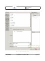
6.2 Project file . . . . . . . . . . . . . . . . . . . . . .
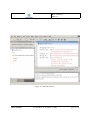
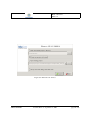
6.2.1 GPS Integrated Development Environment
6.2.2 GPRBuild configuration . . . . . . . . . .
6.3 Test program . . . . . . . . . . . . . . . . . . . .
6.4 Debugging . . . . . . . . . . . . . . . . . . . . . .
.
.
.
.
.
.
.
.
.
.
.
.
.
.
.
.
.
.
.
.
.
.
.
.
.
.
.
.
.
.
.
.
.
.
.
.
.
.
.
.
.
.
.
.
.
.
.
.
.
.
.
.
.
.
.
.
.
.
.
.
.
.
.
.
.
.
.
.
.
.
.
.
.
.
.
.
.
.
.
.
.
.
.
.
.
.
.
.
.
.
.
.
.
.
.
.
.
.
.
.
.
.
.
.
.
.
.
.
.
.
.
.
.
.
.
.
.
.
.
.
.
.
.
.
.
.
.
.
.
.
.
.
.
.
.
.
.
.
.
.
.
.
.
.
.
.
.
.
.
.
.
.
.
.
.
.
.
.
.
.
.
.
.
.
.
.
.
.
.
.
.
.
.
.
.
73
74
74
74
76
81
81
82
VMlab-UPM-TR1
.
.
.
.
.
.
.
.
.
.
.
.
.
.
.
.
.
.
.
.
.
.
.
.
.
.
.
.
.
.
.
.
.
.
.
.
.
.
.
.
.
.
.
.
.
.
.
.
.
.
.
.
.
.
.
.
.
.
.
.
.
.
.
.
.
.
.
.
.
.
.
.
.
.
.
.
.
.
.
.
.
.
.
.
Last Modified on: September 23, 2009
page 6 of 85
Reference: VMLAB-UPM-TR1
Date: 15/09/2009
Issue: 1.5
7
Conclusions
83
Bibliography
85
VMlab-UPM-TR1
Last Modified on: September 23, 2009
page 7 of 85
Reference: VMLAB-UPM-TR1
Date: 15/09/2009
Issue: 1.5
VMlab-UPM-TR1
Last Modified on: September 23, 2009
page 8 of 85
Reference: VMLAB-UPM-TR1
Date: 15/09/2009
Issue: 1.5
Chapter 1
Introduction
1.1
Purpose
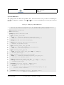
This document provides guidelines for writing device drivers for the ASSERT Virtual Machine. Device drivers
need not contain protocols and algorithms. They are to be made of simple, short and time-effective actions.
Protocols and algorithms are realized in the application code and, to fit the ASSERT methodology, are to respect
the Ravenscar restrictions.
The Wikipedia gives a good definition of what a device driver is:
“In computing, a device driver or software driver is a computer program allowing higher-level computer programs to interact with a hardware device.
A driver typically communicates with the device through the computer bus or communications subsystem to which the hardware is connected. When a calling program invokes a routine in the driver,
the driver issues commands to the device. Once the device sends data back to the driver, the driver
may invoke routines in the original calling program. Drivers are hardware-dependent and operatingsystem-specific. They usually provide the interrupt handling required for any necessary asynchronous
time-dependent hardware interface.”
Writing device drivers requires an in-depth understanding of the hardware functionality. In order to better
illustrate the issues related to hardware and software integration, this document includes an example of a physical communications driver that can be integrated with the logical communication layer of the ASSERT Virtual
Machine. The logical communication layer, which is part of the ASSERT VM middleware, is the higher-level
computer program that interacts with the communication device by means of the device driver.
Detailed knowledge of the computer bus is also needed for driver development. The buses of the GR-RASTA
development platform1 are used in the document as an example. Notwithstanding the notional use of a particular
driver and bus as a case study, the guidelines provided in the document are generic in nature, and are intended to
help developers build a large variety of device drivers and integrate them in the ASSERT Virtual Machine.
1 GR-RASTA is a modular system based on a LEON2 or LEON3 computer, using a cPCI (compact Peripheral Component Interconnect)
backplane bus. See http://www.gaisler.com/doc/gr-rasta_product_sheet.pdf for detailed information.
VMlab-UPM-TR1
Last Modified on: September 23, 2009
page 9 of 85
Reference: VMLAB-UPM-TR1
Date: 15/09/2009
Issue: 1.5
1.2
Scope
The target audience for this document are software engineers who are in charge of writing the lower-level components of onboard computer software.
1.3
1.3.1
Glossary
Acronyms and abbreviations
AHB
ALRM
AMBA
APB
API
ASB
ASSERT
AVM
BAR
cPCI
CCSDS
CPU
DMA
DSU
ECSS
EISA
EEP
EOP
FCT
FIFO
FPGA
FSM
GPS
GR
GRSPW
GNU
HI
I/O
IMASK
IOREQ
IRQ
ISR
Advanced High-performance Bus
Ada Language Reference Manual
Advanced Microcontroller Bus Architecture
Advanced Peripheral Bus
Application Programming Interface
Advanced System Bus
Automated proof-based System and Software Engineering for Real-Time applications
ASSERT Virtual Machine
Base Address Register / Bank Address Register (APB)
Compact Peripheral Component Interconnect
Consultative Committee for Space Data Systems
Central Processing Unit
Direct Memory Access
Debug Support Unit
European Cooperation on Space Standardization
Enhanced Industry Standard Architecture
Error End-of-Packet
End-Of-Packet Marker
Flow Control Token
First-In First-Out
Field Programmable Gate Array
Finite State Machine
GNAT Programming Studio
Gaisler Research
Gaisler Research SpaceWire
GNU is not Unix
High Integrity
Input/Output
Interrupt Mask Register
I/O request
Interrupt request
Interrupt Service Routine
VMlab-UPM-TR1
Last Modified on: September 23, 2009
page 10 of 85
Reference: VMLAB-UPM-TR1
Date: 15/09/2009
Issue: 1.5
LANCE
MEC
N-Chars
OBDH
ORK
PCI
PO
RASTA
RMAP
SOIS
SVAP
SVEP
SVVP
VM
VME
1.4
1.4.1
Local Area Network Controller for Ethernet
Memory Controller
Normal characters (data characters, EOP or EEP)
On-Board Data Handling
Open Ravenscar real-time Kernel
Peripheral Component Interconnect
(Ada) Protected Object
Reference Avionics System Testbench Activity
Remote Memory Access Protocol
CCSDS Spacecraft Onboard Interface Services
Software Validation Plan
Software Verification Plan
Software Verification & Validation Plan
Virtual Machine
Versa Module Europa (IEEE 1014)
Applicable and reference documents
Applicable documents
[A1] Lab activities — Improvement and documentation of the ASSERT Virtual Machine. ESTEC Statement of
Work TEC-SWE/07-104/MP, I1R3. 3 September, 2007.
[A2] Improvement and Documentation of the ASSERT Virtual Machine — Proposal for ESA Statement of Work
Ref: TEC-SWE/07-104/MP. University of Padova, École Nationale Supérieure des Télécommunications,
Universidad Politécnica de Madrid. I1R4. 7 January 2008.
1.4.2
Reference documents
[R1] ASSERT D3.3.2-2: Virtual Machine Architecture Definition. I1R1, July 2007.
[R2] ASSERT D3.3.2-3: Virtual Machine Components Specification. I1R1, July 2007.
[R3] GNATforLEON/ORK+ User Manual. Version 1.1. 18 November, 2008. Available at http://www.dit.
upm.es/ork.
[R4] PolyORB-HI User’s Guide. Available at http://aadl.enst.fr.
1.4.3
Standards
[S1] ECSS-E-ST-40C — Space engineering — Software. March 2009.
[S2] ECSS-E-50-11 Draft F. Remote Memory Access Protocol (RMAP). December 2006
[S3] ECSS-E-ST-50-12C — SpaceWire — Links, nodes, routers and networks. July 2008.
[S4] ISO SC22/WG9. Ada Reference Manual. Language and Standard Libraries. Consolidated Standard ISO/IEC
8652:1995(E) with Technical Corrigendum 1 and Amendment 1, 2005.
VMlab-UPM-TR1
Last Modified on: September 23, 2009
page 11 of 85
Reference: VMLAB-UPM-TR1
Date: 15/09/2009
Issue: 1.5
[S5] ISO SC22/WG14. Programming Languages — C. ISO/IEC 9899:1999.
[S6] ISO SC22/WG15. Portable Operating System Interface (POSIX). ISO/IEC 9945-2003.
1.4.4
Other documents
[D1] ISO/IEC. Guide for the use of the Ada programming language in high integrity systems. Technical report
ISO/IEC TR 15942:2000.
[D2] ISO/IEC. Guide for the use of the Ada Ravenscar Profile in high integrity systems. Technical report ISO/IEC
TR 24718:2005. Based on the University of York Technical Report YCS-2003-348 (2003).
[D3] Christine Ausnit-Hood, Kent A. Johnson, Robert G. Petit IV and Steven B. Opdahl, Ada 95 Quality and
Style. Springer-Verlag, LNCS 1344. 1995.
[D4] AdaCore. GNAT GPL User’s Guide. 2007.
[D5] AdaCore. GNAT Reference Manual. 2007.
[D6] The SPARC architecture manual: Version 8. Revision SAV080SI9308, 1992.
[D7] ATMEL. Rad-Hard 32 bit SPARC V8 Processor AT697E. Rev. 4226E–AERO–09/06.
With errata sheet Rev. 4409C–AERO–05/08.
[D8] GR-CPCI-AT697 Development Board User Manual. Version 1.1, June 2005. Gaisler Research/Pender Electronic Design, 2005.
[D9] GR-RASTA Board User Manual. Gaisler Research/Pender Electronic Design, 2007.
[D10] RASTA Interface Board FPGA User’s Manual. Version 1.0.0, June 2006. Gaisler Research, 2006.
[D11] GRLIB IP Core User’s Manual. Version 1.0.16, June 2007. Jiri Gaisler, Edvin Catovic, Marko Isomäki,
Kritoffer Glembo, Sandi Habinc. Gaisler Research, 2007.
[D12] GRSPW Spacewire Codec IP Core User’s Manual. Gaisler Research, December 2005.
[D13] ARM. AMBA(TM) Specification (Rev 2.0). ARM Limited 1999.
1.5
Overview
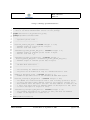
The rest of this document is organised as follows:
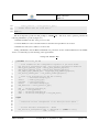
• Chapter 2 recalls basic foundations of computer structure to introduce the device drivers functionality and
the proposed software architecture.
• Chapter 3 describes the mechanisms to define, map, and access device registers in Ada and the peculiarities
of the GNATforLEON tool chain.
• Chapter 4 shows how to handle interrupts in Ada with the restrictions imposed by the Ravenscar Profile and
the characteristics of the ORK+ kernel.
VMlab-UPM-TR1
Last Modified on: September 23, 2009
page 12 of 85
Reference: VMLAB-UPM-TR1
Date: 15/09/2009
Issue: 1.5
• Chapter 5 describes a sample device driver for the SpaceWire chip of the GR-RASTA system.
• Chapter 6 provides guidance about organising device driver source code as well as about compilation and
testing.
• Chapter 7 concludes the report.
VMlab-UPM-TR1
Last Modified on: September 23, 2009
page 13 of 85
Reference: VMLAB-UPM-TR1
Date: 15/09/2009
Issue: 1.5
VMlab-UPM-TR1
Last Modified on: September 23, 2009
page 14 of 85
Reference: VMLAB-UPM-TR1
Date: 15/09/2009
Issue: 1.5
Chapter 2
Driver architecture
The development of a device driver requires a thorough knowledge of the underlying hardware device as well as
the supporting facilities of the target operating system or kernel. This chapter deals with the underlying hardware
devices and gives a description of general hardware devices and the peculiarities of the GR-RASTA system. Then,
the functionality of a device driver is summarized and a general software architecture is described.
2.1
I/O subsystem
Computer systems are composed of three mayor subsystems that interact with one another: CPU (Central Processing Unit), main memory and I/O (Input/Output) subsystem.
The I/O subsystem includes the so-called peripheral devices (or peripherals for short), which permit the system
to interact with the outside environment or provide auxiliary functions, such as timing or additional storage.
Modern CPUs are general-purpose devices, and the logic needed to deal with peripherals is typically placed
in separate devices, called I/O modules or I/O devices. In this way, the CPU only includes the logic needed to
communicate with the I/O modules in a uniform way, and leaves the peripherals management to the I/O modules.
The CPU capabilities required to communicate with the I/O modules are limited to the ability of reading and
writing the I/O module registers, which make up the I/O module interface. As a result, the I/O subsystem of a
modern digital computer is built up from the set of I/O modules connected to the computer.
2.1.1
I/O modules
Peripheral devices are attached to computers by links to I/O modules. These links are used to exchange data as well
as control and status information between I/O modules and peripheral devices. In turn, I/O modules are connected
to the computer through the system bus, and their interface to the CPU side consists of several registers. Device
registers can be classified as:
Status registers: store the status of the attached device. The CPU can check the status of a device by reading its
status registers.
Control registers: accept commands from the CPU which are decoded by the I/O module in order to issue the
corresponding request to the peripheral device.
VMlab-UPM-TR1
Last Modified on: September 23, 2009
page 15 of 85
Reference: VMLAB-UPM-TR1
Date: 15/09/2009
Issue: 1.5
Data registers: perform data buffering in order to decouple the different transfer rates of the main memory and
the peripheral device.
2.1.2
I/O operations
The aim of I/O modules is to provide a simple interface to perform I/O operations on peripheral devices. An I/O
operation consists in transferring data from main memory to a peripheral device or vice-versa.
The amount of data involved in an I/O operation depends on the nature of the peripheral device. For instance,
it can be a byte or character for a keyboard, or a fixed length block for a disk drive. The key issue is that the
timing of I/O operations depends on the individual peripheral device, and therefore device-related events occur
arbitrarily. As a result, the I/O modules and the processor need to be synchronized when performing I/O operations.
Synchronization can be done by polling I/O module status registers. However, a high amount of processor time
may be wasted on waiting until the I/O modules are ready to receive or transmit data (busy waiting). The common
alternative is to make I/O modules signal their asynchronous events by interrupting the processor through dedicated
bus lines (interrupt request lines).
When interrupts are used, after the processor issues a command for a peripheral device, it switches to doing
something else (typically switching to another thread of execution). When the command is completed, the I/O
module signals an interrupt. The processor reacts to the interrupt by saving the execution context of the current
thread and transferring control to an Interrupt Service Routine (ISR), which completes the I/O operation, possibly
by transferring additional data to or from the main memory.
The ASSERT Virtual Machine kernel provides a mechanism for setting user-defined procedures as ISR for the
11 interrupt sources available in the LEON processor. The standard Ada interrupt support approach is used for this
purpose, as explained in chapter 4.
2.1.3
DMA I/O operations
An I/O operation on a block peripheral device implies transferring a large amount of data, typically several hundreds or even thousands of bytes. In these cases, it is more effective to directly transfer the data between the
I/O module and the memory without any intervention from the CPU. This schema, called Direct Memory Access
(DMA), is widely used with block devices such as communication devices or disk drives.
It should be noticed that the I/O module must issue an interrupt in order to signal the completion of the I/O
operation to the CPU. The interrupt service routine polls the status registers so as to check if the operation has been
successfully completed.
It is possible to go further in reducing processor involvement in performing I/O operations. DMA I/O operations need little processor attention when an operation finishes, but issuing commands to I/O modules implies
transferring not only the command itself, but the memory address of the buffer and the amount of data involved
as well. Therefore, it is effective to create a structure in memory with several linked buffers, and then send an
access to it to the concerned I/O module at initialization time. In this way, the processor only has to command
the operation and service the completion interrupt routine. Furthermore, bidirectional peripheral devices usually
manage two sets of linked buffers, for input and output operations. Some I/O modules, such as LANCEs,1 awake
periodically and check for new output operations by polling the status of the output buffers, which in this case are
usually called rings.
Communication devices usually have the ability to deal with so-called linked DMA I/O operations. As a result,
the initialization procedure is more complex because it is not just a matter of setting proper values in I/O module
registers, but setting up the memory structures for linked I/O operations as well.
1 Local
Area Network Controller for Ethernet
VMlab-UPM-TR1
Last Modified on: September 23, 2009
page 16 of 85
Reference: VMLAB-UPM-TR1
Date: 15/09/2009
Issue: 1.5
2.2
Device interface
The I/O modules or devices have several registers which need to be allocated and make them accessible to the
processor. Processors may use the same instructions for accessing device registers as for main memory, or may
have special instructions for accessing device registers.
Processors with special instructions for accessing device registers have different address spaces for memory
locations and for I/O device registers. This scheme is commonly referred to as “isolated I/O map”: additional
bus lines (typically I/O request, IOREQ, lines) are needed to access the I/O map. Bus cycles using these lines are
generated when I/O instructions are executed (typically named in and out).
On the other hand, the most common approach is to share a single address space for memory locations and
I/O device registers. This is commonly known as “memory-mapped I/O”. Under this approach, load and store
instructions are used for accessing both memory and I/O devices.
SPARC processors use memory-mapped I/O and thus it is possible to use Ada representation clauses (see
section 3.1) to access I/O module registers, as shown in chapter 3.
2.2.1
Bus architecture
Although there are other ways for CPU, main memory and I/O subsystem to communicate with each other, most
commonly these subsystems are connected by means of a computer bus or, more often, a computer bus hierarchy. Therefore, the bus structure for accessing the I/O module interfaces has to be defined before starting the
development of device drivers.
A key issue is the allocation of device registers in the bus address space. I/O addresses for a single device are
always allocated in a contiguous region, and all that is needed is to set the so-called base address for the device.
Some modular buses, such as VME or EISA, provide jumpers or micro-switches for manually setting the base
addresses. However, setting up a system-wide base on several boards is error prone and must be done carefully.
Other modular buses, such as PCI, do not provide such low-level mechanisms, and the base address is written in
registers by using a separate configuration address space.
The configuration address space uses a so-called geographical addressing scheme, i.e. boards are addressed by
their physical location, which is where the boards are inserted in the bus backplane. Locations or slot numbers are
hard-wired into the backplane. It must be noticed that this approach forces a predefined number of addresses for
boards and thus can only be used for configuration.
As a result, as part of system startup a routine must initialize the configuration registers in order to properly set
up the system I/O configuration. This capability is usually known as “plug and play”. The cPCI modular bus of the
GR-RASTA system has a set of configuration registers that are accessed by geographical addressing, and therefore
a plug and play routine has to be developed in order to initialize the operation of I/O devices. On the other hand,
the the Advanced Microcontroller Bus Architecture (AMBA) bus, which is also part of the GR-RASTA subsystem,
uses a centralized address decoding scheme, and therefore the AMBA plug and play routine does not have to set
up any address registers. Its main function is to explore the AMBA configuration records of the devices in order to
find their preassigned base addresses.
It is worth mentioning that other bus configuration features such as interrupt request lines, bus request lines,
etc. are also set up in the same way.
2.2.2
Bus hierarchy
Computer systems with a large number of devices with transfer speeds several orders of magnitude apart use
multiple buses instead of a single bus interconnecting all the devices. These buses are generally laid out in a
VMlab-UPM-TR1
Last Modified on: September 23, 2009
page 17 of 85
Reference: VMLAB-UPM-TR1
Date: 15/09/2009
Issue: 1.5
hierarchy, with the higher speed bus at the top and the lower speed buses at the bottom. In this way, there is no loss
of performance due to bus length and saturation.
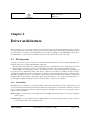
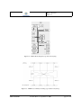
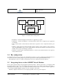
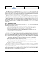
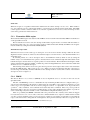
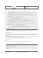
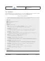
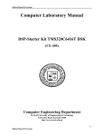
Bus hierarchies can be found at all levels inside a computer system. In particular, LEON processors use the
AMBA bus hierarchy which is shown in figure 2.1.
Figure 2.1: A typical AMBA system (reproduced from [D13]).
The AMBA specification [D13] defines three kinds of buses:
Advanced High-performance Bus (AHB): this is a high bandwidth bus intended to be used at the top of the
hierarchy, i.e. to connect processors with main memory and fast DMA I/O devices.
Advanced System Bus (ASB): this is also a high bandwidth bus intended for use at the top of the hierarchy.
However, it does not support burst transfers, and therefore there is a performance penalty when using it to
connect cache memories or burst DMA devices such as GR-SpaceWire.
Advanced Peripheral Bus (APB): this is a simpler and slower bus intended to be used at the lower levels of the
bus hierarchy. It usually connects slow I/O devices, and it communicates with the AHB or ASB through a
bridge.
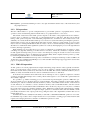
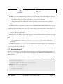
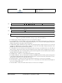
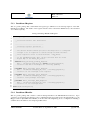
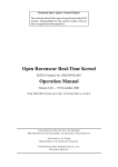
The ATMEL AT697E LEON2-FT processor has the structure shown in figure 2.2. It uses AHB as the local
bus, APB as the system bus, and PCI as an expansion bus.
System software is usually unaware of the bus hierarchy, aside from the configuration of the plug-and-play
feature. However, it is important to take into account the “endianness” of the different buses of the hierarchy as it
has a strong influence on the definition of device registers.
Endianness has to do with byte ordering in multibyte scalar values. Some machines store the least significant
byte in the lowest byte address: this disposition is known as little-endian. Other machines store the most significant
byte in the lowest byte address: this arrangement is known as big-endian 2 .
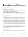
The SPARC v7 and v8 architectures, and therefore LEON, are big-endian. This is also the the byte ordering
of the AMBA buses in LEON processors. However, the PCI bus is little-endian, as it was mainly developed for
Intel x86 processors. In this way, I/O device multibyte registers will suffer byte twisting as shown in figure 2.3.
This issue must be taken into account for PCI I/O device multibyte registers as well as for DMA transfers.
Accordingly, PCI hosts and PCI DMA I/O devices must be properly initialized.
2 Both
terms come from Gulliver’s Travels by Jonathan Swift and refer to the ways of slicing boiled eggs open for English breakfast.
VMlab-UPM-TR1
Last Modified on: September 23, 2009
page 18 of 85
Reference: VMLAB-UPM-TR1
Date: 15/09/2009
Issue: 1.5
Figure 2.2: AT697 Block Diagram (reproduced from [D7]).
Figure 2.3: AMBA bus to PCI byte twisting (reproduced from [D11]).
VMlab-UPM-TR1
Last Modified on: September 23, 2009
page 19 of 85
Reference: VMLAB-UPM-TR1
Date: 15/09/2009
Issue: 1.5
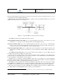
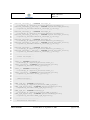
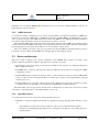
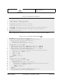
Figure 2.4: GR-CPCI-AT697 CPU Board Block Diagram (reproduced from [D8]).
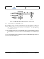
2.2.3
Bus hierarchy in the GR-RASTA system
The GR-RASTA is a computer system built on a cPCI backplane bus. This modular computer has two cPCI boards:
GR-CPCI-AT697: this is the processor board. It includes an Atmel AT697 LEON2-FT device, as well as memory,
a debug support unit and some I/O devices. Its structure is shown in figure 2.4. It has a PCI-AMBA bridge
to access the cPCI backplane bus.
GR-CPCI-XC4V: this is an interface board based on a FPGA which has several I/O modules, including three
SpaceWire links. Its design is based on an AMBA AHB to which the high-bandwidth units are connected.
Low-bandwidth units are connected to the APB. It also has a PCI-AMBA bridge to access the cPCI backplane
bus.
It must be noticed that I/O modules in the GR-CPCI-XC4V board are accessed through a PCI-AMBA bridge.
As a result, data going from I/O modules to main memory or CPU cross two PCI-AMBA bridges and suffer two
byte twists to revert to the original byte order.
VMlab-UPM-TR1
Last Modified on: September 23, 2009
page 20 of 85
Reference: VMLAB-UPM-TR1
Date: 15/09/2009
Issue: 1.5
Figure 2.5: RASTA Interface Board Block Diagram (reproduced from [D10]).
VMlab-UPM-TR1
Last Modified on: September 23, 2009
page 21 of 85
Reference: VMLAB-UPM-TR1
Date: 15/09/2009
Issue: 1.5
2.3
Software architecture for device drivers
According to the hardware organization described in the previous section, a device driver has to deal with peripheral
buses, in addition to device control, data registers and interrupts. The software architecture should ideally reflect
this organization, by providing separate components to handle peripheral devices and buses.
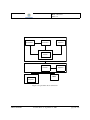
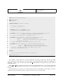
Figure 2.6 shows a generic architecture for a communications driver. It is modelled after other software architectures that have been successfully implemented for other communications devices [Mor95, Ber05, Sal08]. A
sample driver built on this architecture is described in chapter 5.
driver!
board!
PCI!
AMBA!
Figure 2.6: Generic driver architecture.
As shown in the figure, there are four components which support the communications device itself, the I/O
board mechanisms, the PCI functionality, and the AMBA bus, respectively. It must be noticed that the functionality
provided by the PCI hierarchy, as well as the AMBA bus exploration,3 can be used by all the drivers to configure
and locate PCI and AMBA devices, and therefore both PCI and AMBA have their own hierarchy.
• The AMBA component provides data type definitions and operations for scanning the AMBA configuration
records.
• The PCI component provides data type definitions and operations for reading and writing the PCI configuration registers.
• The Board component provides a higher-level interface for AMBA and PCI bus initialization, as well as
hooks for redirecting the board interrupt mechanism to the driver interrupt handler.
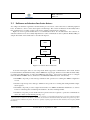
• The Driver component provides all the data and operations that are required to operate the communications
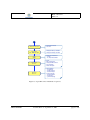
device. It contains several internal parts (fig. 2.7):
3 An Ada program will normally make use of a library of program units of general utility. The language provides means whereby individual
organizations can construct their own libraries. All libraries are structured in a hierarchical manner; this enables the logical decomposition
of a subsystem into individual components. The text of a separately compiled program unit must name the library units it requires [ALRM
Introduction].
VMlab-UPM-TR1
Last Modified on: September 23, 2009
page 22 of 85
Reference: VMLAB-UPM-TR1
Date: 15/09/2009
Issue: 1.5
Driver
Parameters
HLInterface
Registers
Core
Interrupt
Handler
Figure 2.7: Generic driver decomposition.
– HLInterface: contains the higher-level interface for application programs.
– Parameters: contains the definitions of all the parameters that can be configured by the application
programmer.
– Core: contains all the code that interacts with the device registers in order to implement the I/O operations.
– Handler: contains the device interrupt handler, which is invoked on the completion of I/O operations.
Since the GR-RASTA board provides a single hardware interrupt, this handler is invoked by the board
handler at the receipt of an interrupt occurrence.
– Registers: contains register and bit field definitions, as well as other definitions that can be required to
interact with the device.
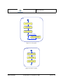
2.4
Bus configuration
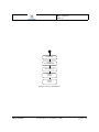
As explained in the previous sections, the peripheral buses must be properly configured and initialized before a
device driver can start operating. Figure 2.8 provides a general view of the required initialization steps.
The initialization steps for a sample communications driver are explained in detail in chapter 5.
2.5
Integrating drivers in the ASSERT Virtual Machine
Device drivers interact with low-level hardware and kernel features. Therefore they have to be integrated with
the real-time kernel component of the AVM. To this end, the source code of all the components of the driver —
including the bus modules— has to be compiled and linked with the kernel code (and also with the application
code) using the GNATforLEON compilation system. See [R3] for the details.
Detailed compilation instructions for the sample SpaceWire driver are given in chapter 6.
VMlab-UPM-TR1
Last Modified on: September 23, 2009
page 23 of 85
Reference: VMLAB-UPM-TR1
Date: 15/09/2009
Issue: 1.5
Initialize PCI
Configure
PCI-AMBA bridge
Scan AMBA bus
Configure
device
Operate
device
Figure 2.8: Device initialization.
VMlab-UPM-TR1
Last Modified on: September 23, 2009
page 24 of 85
Reference: VMLAB-UPM-TR1
Date: 15/09/2009
Issue: 1.5
Chapter 3
Device register management
A device interface consists of a set of registers which are read (loaded from) or written (stored into) with proper
values in order to interact with the hardware devices. For the sake of program abstraction and readability, device
registers have to be represented in an abstract way.
In this chapter, the facilities of the Ada programming language are used to specify the implementation of data
types that correspond to the various kinds of device registers which can be found in a particular architecture. These
facilities are the so-called representation clauses, which can be used to specify the way Ada objects and types are
mapped onto the underlying device registers.
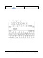
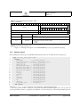
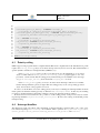
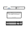
3.1
Device register definition
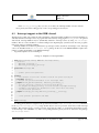
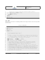
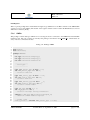
In order to illustrate the use of representation clauses, the 32-bit LEON2 interrupt mask register (IMASK) will
be used. Its 16 most significant bits can be used to enable or disable the corresponding interrupt in the LEON2
processor (figure 3.1).
3.1.1
Internal codes
The first step is to define an enumeration type that corresponds to the enable and disable status of each IMASK
bit.
1
type Interrupt_Status is (Disabled, Enabled);
In order to ensure that the internal code representation for Disabled and Enabled is 0 and 1, respectively, the
following enumeration representation clause should be used:
1
for Interrupt_Status use (Disabled => 0, Enabled => 1);
Notice that the predefined Boolean type could be used in this case because the language defines the low-level
representation of False and True to be 0 and 1, respectively. However, defining an enumeration type provides
better readability and is required for multi-bit internal codes.
Furthermore, the corresponding representation clauses can be included in the private part of the package. In
this way, implementation details are hidden and readability is improved.
VMlab-UPM-TR1
Last Modified on: September 23, 2009
page 25 of 85
Reference: VMLAB-UPM-TR1
Date: 15/09/2009
Issue: 1.5
AT697
Interrupt Registers
11
10
9
8
7
6
5
4
3
2
1
imask[15:1]
Mnemonic
I/O3
Timer1
of the AT697E LEON2 processor (reproduced from [D7]).
19 18
17
16 15 14
13 12
11
10
9
8
7
6
5
4
3
2
1
I/O3
Timer1
Timer2
unused
DSU
unused
unused
PCI
Register layout
unused
ipend[15:1]
reserved
After defining the required types, the LEON2 interrupt mask register can be defined in the following way:
r/w
r
0
reserved
20
AMBA
22 21
UART2
23
UART1
26 25 24
Timer2
Interrupt mask
indicates whether an interrupt is masked or enabled
‘0’ = masked
‘1’ = enabled
I/O0
imask[15:1]
Interrupt level
indicates whether an interrupt belongs to priority level 1 (ILEVEL[n]=1) or level 0 (ILEVEL[n]=0).
I/O1
15..1
Description
I/O2
ilevel[15:1]
unused
x
DSU
r/w
xxxx xxxx xxxx xxx
unused
r/w
x
unused
r/w
PCI
r/w
Table 68. Interrupt Pending Register - ITP
Address =
0x80000094
Figure
3.1: Interrupt mask register
3.1.2
0
reserved
13 12
xxxx xxxx xxxx xxx
31..17
29 28 27
16 15 14
ilevel[15:1]
Bit Number
31 30
17
AMBA
19 18
UART2
20
I/O0
22 21
UART1
23
I/O1
26 25 24
unused
29 28 27
reserved
31 30
I/O2
Table 67. Interrupt Mask and Priority Register - ITMP
Address = 0x80000090
r/w
reserved
AMBA
UART2
UART1
I/O0
I/O1
I/O2
I/O3
Timer1
Timer2
unused
DSU
unused
unused
PCI
unused
xxxx xxxx xxxx xxxx
0
0
0
0
0
0
0
0
0
0
0
0
0
0
0
x
1
type Interrupt_Mask_Register
is
2
record
Bit Number
Mnemonic
Description
3
Reserved1
: Interrupt_Status;
Interrupt pending
4
Correctable_Error_In_Memory
: Interrupt_Status;
whether an interrupt is pending
15..1
5
UART_2_RX_TXipend[15:1]
: indicates
Interrupt_Status;
“1” = interrupt pending
6
UART_1_RX_TX
: “0”Interrupt_Status;
= interrupt not pending
7
External_Interrupt_0 : Interrupt_Status;
When the:IUInterrupt_Status;
acknowledges the interrupt, the corresponding pending bit is automatically
8
External_Interrupt_1
cleared.
9
External_Interrupt_2 : Interrupt_Status;
10
External_Interrupt_3 : Interrupt_Status;
Force Register - ITF
11 Table 69. Interrupt
Timer_1
: Interrupt_Status;
12 Address = 0x80000098
Timer_2
: Interrupt_Status;
28 27 26 25 24 23 22 21 20
18 17 16 15 14 13 12 11 10 9
8
7
6
5
4
3
2
1
0
13 31 30 29 Unused_1
: 19
Interrupt_Status;
14
DSU
: Interrupt_Status;
iforce[15:1]
15
Unused_2 reserved
: Interrupt_Status;
16
Unused_3
: Interrupt_Status;
17
PCI
: Interrupt_Status;
r/w
r/w
r/w
18
Unused_4
: Interrupt_Status;
19
Interrupt_Level
: Unsigned_16;
xxxx xxxx xxxx xxxx
0
0
0
0
0
0
0
0
0
0
0
0
0
0
0
x
20
end record;
Where the Unsigned_16 type is assumed to be represented as a 16-bit unsigned integer.
103
The order, position and size of the basic components must match the actual register layout. Ada provides the
4226E–AERO–09/06
record representation clause to specify the representation of records. The layout of the interrupt mask register can
VMlab-UPM-TR1
Last Modified on: September 23, 2009
page 26 of 85
Reference: VMLAB-UPM-TR1
Date: 15/09/2009
Issue: 1.5
be defined as follows:
1
2
3
4
5
6
7
8
9
10
11
12
13
14
15
16
17
18
19
20
for Interrupt_Mask_Register use
record
Reserved1
at 0 range 31 .. 31;
Correctable_Error_In_Memory at 0 range 30 .. 30;
UART_2_RX_TX
at 0 range 29 .. 29;
UART_1_RX_TX
at 0 range 28 .. 28;
External_Interrupt_0 at 0 range 27 .. 27;
External_Interrupt_1 at 0 range 26 .. 26;
External_Interrupt_2 at 0 range 25 .. 25;
External_Interrupt_3 at 0 range 24 .. 24;
Timer_1
at 0 range 23 .. 23;
Timer_2
at 0 range 22 .. 22;
Unused_1
at 0 range 21 .. 21;
DSU
at 0 range 20 .. 20;
Unused_2
at 0 range 19 .. 19;
Unused_3
at 0 range 18 .. 18;
PCI
at 0 range 17 .. 17;
Unused_4
at 0 range 16 .. 16;
Interrupt_Level
at 0 range 0 .. 15;
end record;
The bit fields are specified by ranges which correspond with the actual position and size of the hardware
register. Notice that the SPARC v8 architecture has a big-endian representation, which means that the first byte
of a 32-bit word is the most significant one, i.e. the leftmost byte in figure 3.1. The ALRM (13.5.3) defines the
numbering of bits in the following way
If Word_Size = Storage_Unit, the default bit ordering is implementation defined. If Word_Size
> Storage_Unit, the default bit ordering is the same as the ordering of storage elements in a word,
when interpreted as an integer.
Consequently, since the order of the storage elements in SPARC is big-endian, the default bit ordering in Ada
is such that bit 0 is the leftmost bit in figure 3.1. This is contrary to the usual practice, and to the bit numbering
in the SPARC manual [D6] and the AT697E manual [D7]. This explains the difference between the numbering of
bits in the above listing and the figure.
The following representation clauses are also needed to specify the total size and the alignment of the register
in the I/O address space:
1
2
for Interrupt_Mask_Register’Size use 32;
for Interrupt_Mask_Register’Alignment use 4;
The Size clause guarantees that at least 32 bits are used for objects of the type. The Alignment clause
guarantees that aliased, imported, or exported objects of the type will have addresses divisible by 4.
In order to avoid compiler optimizations that can lead to an improper layout, the following pragma must be
included:
1
pragma Pack (Interrupt_Mask_Register);
VMlab-UPM-TR1
Last Modified on: September 23, 2009
page 27 of 85
Reference: VMLAB-UPM-TR1
Date: 15/09/2009
Issue: 1.5
Pragma Pack specifies that storage minimization should be the main criterion when selecting the representation
of the composite type. The components should be packed as tightly as possible subject to their sizes, and subject
to the record representation clauses.
The GNAT compiler generates initialization procedures for objects of packed Boolean array types and record
types that have components of these types. Therefore, the following specific GNAT pragma must be used in order
to avoid undesirable initialization which would result in improper values being set in the hardware register.
1
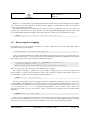
3.2
pragma Suppress_Initialization (Interrupt_Mask_Register);
Device registers mapping
Now that the type has been completely defined, it is possible to define the object for the actual register. This is
done with an Ada object declaration.
1
Interrupt_Mask : Interrupt_Mask_Register;
As above explained, initialization is usually undesirable because the hardware sets the proper values after reset.
The declared object has to correspond (in layout) to the actual interrupt mask register, which has a fixed address
in the address space. This is achieved with the following declarations:
1
2
3
Interrupt_Mask_Register_Address : constant System.Address :=
System’To_Address (16#8000_0090#);
for Interrupt_Mask’Address use Interrupt_Mask_Register_Address;
In this way, the object is allocated exactly at the hardware register address.
The compiler can attempt to optimize the code by reading or writing a local copy of the object instead of the
memory address. To prevent such optimizations and force the compiler to generate read and write operations at
the actual memory address, the following pragma must be included:
1
pragma Volatile (Interrupt_Mask);
The above representation clauses and pragmas should be enough in the general case. However, the memory
controller (MEC) of the LEON2 processors raises memory exceptions when undesirable instructions such as STH
(store half word) are generated, because accessing the whole word is mandatory. The workaround is to use pragma
Atomic instead of pragma Volatile, together with using auxiliary or mirror objects in order to always read
and update the whole object (see next section). This is a clean solution, although with some small semantic
differences.
1
pragma Atomic (Interrupt_Mask);
In this way the compiler back-end generates word instructions when writing the object, because an update of
an atomic object is indivisible from a concurrency point of view. Nothing is said in [ALRM, C6] about the reading
of the object; however, tests have shown that reading the object is also atomic when using the pragma.
VMlab-UPM-TR1
Last Modified on: September 23, 2009
page 28 of 85
Reference: VMLAB-UPM-TR1
Date: 15/09/2009
Issue: 1.5
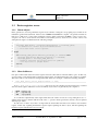
3.3
3.3.1
Device registers access
Mirror objects
In the general case, accessing a hardware register is just a matter of using the corresponding object, which can be
included in general Ada statements. However, the ASSERT Virtual Machine compiler1 can generate instructions
that access a half word or a byte when reading the registers. This would cause the MEC to raise a storage error
exception. In order to avoid such incorrect behavior, an auxiliary (mirror) object has to be used in order to read
and update the register, as illustrated in the following example:
1
2
3
4
5
6
7
8
9
10
11
12
13
14
...
Interrupt_Mask_Mirror : Interrupt_Mask_Register := Interrupt_Mask;
-- Declaration of a mirror object initialized with
--+ the actual value of the register.
...
begin
...
if Interrupt_Mask_Mirror.External_Interrupt_2 = Disabled then
Interrupt_Mask_Mirror.External_Interrupt_2 := Enabled;
Interrupt_Mask := Interrupt_Mask_Mirror;
-- Compiler generates word instructions for updating
--+ the object due to pragma Atomic
end if;
...
3.3.2
Shared addresses
It is quite common that status and control registers share the same address in the I/O address space. In this way,
a read operation on the shared address returns the status register, and when writing the control register is updated.
This may result in some statements causing undesirable effects. For example, consider the following statement:
1
Byte_Wide_Device_Control_Register.Reset := True;
As Byte_Wide_Device_Control_Register has a byte size, the compiler generates instructions to read and
write the whole register without the need of an auxiliary object. The code generated by the compiler is:
1
2
3
ldub
or
stb
[%g2+3], %g1
%g1, 64, %g1
%g1, [%g2+3]
As a result the complementary status register that shares the address is read, the corresponding bit is set to 1,
and the status register is written with the result of the or operation. In the general case, the bit codes are updated
with improper values.
In such cases, a mirror object has to be kept with the actual values that have been written to the hardware
register. In this way, updating the hardware register requires updating the mirror object, and then updating the
hardware register with the mirror object contents.
1 gcc-4.1.3
in the current version
VMlab-UPM-TR1
Last Modified on: September 23, 2009
page 29 of 85
Reference: VMLAB-UPM-TR1
Date: 15/09/2009
Issue: 1.5
1
2
3
4
5
6
7
8
Byte_Wide_Device_Control_Register_Mirror :
Type_Byte_Wide_Device_Control_Register := Control_Register_Initial_Values;
...
begin
...
Byte_Wide_Device_Control_Register_Mirror.Reset := True;
Byte_Wide_Device_Control_Register := Byte_Wide_Device_Control_Register_Mirror;
...
It must be noticed that updates may in principle be performed by several tasks in a concurrent way, so that
race-condition situations may consequently arise. Therefore, both updates must be atomic and thus a protected
object should be used to encapsulate them.
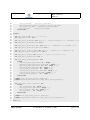
3.4
Example
As an example, consider a 3-axis robotic arm with a grabber claw, 4 DC motors, 4 limit or reference switches,
and 4 pulse counter switches for travel measurement. The robotic arm is connected through 8 digital inputs to
read the status of the 8 switches and 8 digital output to command the 4 digital motors. There are 3 different motor
commands and one unused code.
The digital inputs and outputs are grouped in bytes mapped onto the I/O address space, and it can thus be
considered the status and control register of the robot. The following Ada package is a self-explanatory abstraction
of the robot:
Listing 3.1: Register layout definition
1
2
3
4
5
6
7
8
9
10
11
12
13
14
15
16
17
18
19
20
21
22
package Robot is
type
type
type
type
type
Type_Switch is (On, Off);
Type_Motor_Turntable is (Stop, Counterclockwise, Clockwise);
Type_Motor_Horizontal_Axis is (Stop, Backward, Forward);
Type_Motor_Vertical_Axis is (Stop, Upward, Downward);
Type_Motor_Gripper is (Stop, Open, Close);
type Type_Robot_Status_Register is
record
Reference_Switch_Turntable : Type_Switch;
Reference_Switch_Horizontal_Axis : Type_Switch;
Reference_Switch_Vertical_Axis : Type_Switch;
Reference_Switch_Gripper : Type_Switch;
Pulse_Counter_Turntable : Type_Switch;
Pulse_Counter_Horizontal_Axis : Type_Switch;
Pulse_Counter_Vertical_Axis : Type_Switch;
Pulse_Counter_Gripper
: Type_Switch;
end record;
type Type_Robot_Control_Register is
record
VMlab-UPM-TR1
Last Modified on: September 23, 2009
page 30 of 85
Reference: VMLAB-UPM-TR1
Date: 15/09/2009
Issue: 1.5
23
24
25
26
27
28
29
30
31
32
33
34
35
36
37
38
39
40
41
42
43
44
45
46
47
48
49
50
51
52
53
54
55
56
57
58
59
60
61
62
63
64
65
66
67
68
69
70
71
72
Motor_Turntable : Type_Motor_Turntable;
Motor_Horizontal_Axis : Type_Motor_Horizontal_Axis;
Motor_Vertical_Axis : Type_Motor_Vertical_Axis;
Motor_Gripper
: Type_Motor_Gripper;
end record;
private
for Type_Switch use (On => 0, Off =>1);
for Type_Switch’size use 1;
for Type_Motor_Turntable use (Stop => 0, Counterclockwise => 1, Clockwise => 2);
for Type_Motor_Turntable’size use 2;
for Type_Motor_Horizontal_Axis use (Stop => 0, Backward => 1, Forward => 2);
for Type_Motor_Horizontal_Axis’size use 2;
for Type_Motor_Vertical_Axis use (Stop => 0, Upward => 1, Downward => 2);
for Type_Motor_Vertical_Axis’size use 2;
for Type_Motor_Gripper use (Stop => 0, Open => 1, Close => 2);
for Type_Motor_Gripper’size use 2;
for Type_Robot_Status_Register use
record
Reference_Switch_Turntable at 0 range 0..0;
Reference_Switch_Horizontal_Axis at 0 range 1..1;
Reference_Switch_Vertical_Axis at 0 range 2..2;
Reference_Switch_Gripper at 0 range 3..3;
Pulse_Counter_Turntable at 0 range 4..4;
Pulse_Counter_Horizontal_Axis at 0 range 5..5;
Pulse_Counter_Vertical_Axis at 0 range 6..6;
Pulse_Counter_Gripper
at 0 range 7..7;
end record;
pragma Pack (Type_Robot_Status_Register);
pragma Suppress_Initialization (Type_Robot_Status_Register);
for Type_Robot_Control_Register use
record
Motor_Turntable at 0 range 0..1;
Motor_Horizontal_Axis at 0 range 2..3;
Motor_Vertical_Axis at 0 range 4..5;
Motor_Gripper
at 0 range 6..7;
end record;
pragma Pack (Type_Robot_Control_Register);
pragma Suppress_Initialization (Type_Robot_Control_Register);
end Robot;
VMlab-UPM-TR1
Last Modified on: September 23, 2009
page 31 of 85
Reference: VMLAB-UPM-TR1
Date: 15/09/2009
Issue: 1.5
If the address of the status and control register is 16#8000_8000#, the registers can be defined in the following
child library unit:
Listing 3.2: Register mapping
1
2
3
4
5
6
7
8
9
10
11
12
13
14
15
16
17
18
with System;
package Robot.Registers is
Robot_Control_Register_Address : constant System.Address
:= System’To_Address (16#80_008_000#);
Robot_Status_Register_Address : constant System.Address
:= System’To_Address (16#80_008_000#);
Robot_Control : Type_Robot_Control_Register;
for Robot_Control’Address use Robot_Control_Register_Address;
pragma Atomic (Robot_Control);
Robot_Status : Type_Robot_Status_Register;
for Robot_Status’Address use Robot_Status_Register_Address;
pragma Atomic (Robot_Status);
end Robot.Registers;
Now a main procedure for moving the arm upward until the limit in a polling-based manner can be coded in
the following naive way:
Listing 3.3: Naive register usage
1
2
3
4
5
6
7
8
9
10
11
12
13
14
with Robot.Registers;
use Robot.Registers;
use Robot;
procedure Upward_Naive is
begin
while Robot_Status.Reference_Switch_Vertical_Axis = Off loop
Robot_Control.Motor_Vertical_Axis := Upward;
end loop;
Robot_Control.Motor_Vertical_Axis := Stop;
end Upward_Naive;
VMlab-UPM-TR1
Last Modified on: September 23, 2009
page 32 of 85
Reference: VMLAB-UPM-TR1
Date: 15/09/2009
Issue: 1.5
It must be noticed that the code shown in listing 3.3 commands the vertical axis motor properly, but the other
3 motors are also inadvertently commanded with the corresponding bit codes of the Robot_Status register. As a
result, undesirable actions could be performed because the following assembly code is generated by the compiler
to start the motor:
1
2
3
4
ldub
and
or
stb
[%g2], %g1
%g1, −13, %g1
%g1, 4, %g1
%g1, [%g2]
The proper way to circumvent the problem is to use a mirror register as in the following procedure:
Listing 3.4: Proper register usage
1
2
3
4
5
6
7
8
9
10
11
12
13
14
15
16
with Robot.Registers;
use Robot.Registers;
use Robot;
procedure Upward is
Robot_Control_Mirror : Type_Robot_Control_Register := (Stop, Stop, Stop, Stop);
begin
while Robot_Status.Reference_Switch_Vertical_Axis = Off loop
Robot_Control_Mirror.Motor_Vertical_Axis := Upward;
Robot_Control := Robot_Control_Mirror;
end loop;
Robot_Control_Mirror.Motor_Vertical_Axis := Stop;
Robot_Control := Robot_Control_Mirror;
end Upward;
VMlab-UPM-TR1
Last Modified on: September 23, 2009
page 33 of 85
Reference: VMLAB-UPM-TR1
Date: 15/09/2009
Issue: 1.5
VMlab-UPM-TR1
Last Modified on: September 23, 2009
page 34 of 85
Reference: VMLAB-UPM-TR1
Date: 15/09/2009
Issue: 1.5
Chapter 4
Interrupt handling
Hardware devices indicate events requiring attention from the CPU by issuing interrupt requests. Therefore, a
key part of device drivers has to deal with interrupt handling. Interrupts can be handled in Ada by attaching
parameterless protected procedures to hardware interrupt sources. In this way, parameterless protected procedures
are executed when the hardware signals the associated interrupts.
The dynamic semantics of Ada interrupt handling is fully supported by the ASSERT Virtual Machine. The
ALRM (C.3) defines the dynamic semantics as follows:
An interrupt represents a class of events that are detected by the hardware or the system software.
Interrupts are said to occur. An occurrence of an interrupt is separable into generation and delivery.
Generation of an interrupt is the event in the underlying hardware or system that makes the interrupt
available to the program. Delivery is the action that invokes part of the program as response to the interrupt occurrence. Between generation and delivery, the interrupt occurrence (or interrupt) is pending.
Some or all interrupts may be blocked. When an interrupt is blocked, all occurrences of that interrupt
are prevented from being delivered. Certain interrupts are reserved. The set of reserved interrupts is
implementation defined. A reserved interrupt is either an interrupt for which user-defined handlers are
not supported, or one which already has an attached handler by some other implementation-defined
means. Program units can be connected to non-reserved interrupts. While connected, the program
unit is said to be attached to that interrupt. The execution of that program unit, the interrupt handler,
is invoked upon delivery of the interrupt occurrence.
While a handler is attached to an interrupt, it is called once for each delivered occurrence of that
interrupt. While the handler executes, the corresponding interrupt is blocked.
While an interrupt is blocked, all occurrences of that interrupt are prevented from being delivered.
Whether such occurrences remain pending or are lost is implementation defined.
Each interrupt has a default treatment which determines the system’s response to an occurrence
of that interrupt when no user-defined handler is attached. The set of possible default treatments is
implementation defined, as is the method (if one exists) for configuring the default treatments for
interrupts.
An interrupt is delivered to the handler (or default treatment) that is in effect for that interrupt at
the time of delivery.
An exception propagated from a handler that is invoked by an interrupt has no effect.
VMlab-UPM-TR1
Last Modified on: September 23, 2009
page 35 of 85
Reference: VMLAB-UPM-TR1
Date: 15/09/2009
Issue: 1.5
If the Ceiling_Locking policy (see D.3) is in effect, the interrupt handler executes with the
active priority that is the ceiling priority of the corresponding protected object.
4.1
Interrupt support in the ORK+ kernel
The Ravenscar profile only permits the static attachment of interrupt handlers. In Ravescar, interrupt handlers are
statically attached to interrupt sources at program elaboration time by using pragma Attach_Handler. In general
Ada instead, interrupt handlers may be dynamically attached to interrupt sources by using Ada.Interrupts
facilities. The use of those facilities is considered dangerous in high-integrity systems because incorrect programs
may lead to improper interrupt handling.
Interrupt handlers are declared as parameterless protected procedures, attached to an interrupt source. Interrupt
sources are identified in the Ada.Interrupts.Names package. In the case of the GNATforLEON compiler, this
package contains the identifiers of the LEON2 interrupts.
A general template is shown in listing 4.1.
Listing 4.1: Template for interrupt handlers.
1
2
3
4
5
6
7
8
9
10
11
12
13
14
15
16
17
18
19
20
21
22
23
24
with Ada.Interrupt.Names; use Ada.Interrupt.Names;
-- used for:
-External_Interrupt_0,
-External_Interrupt_0_Priority
protected Interrupt is
-- public protected operations
private
-- The handler need not be visible outside the protected object
procedure Handler;
-- Attach the protected handler to an interrupt name:
pragma Attach_Handler(Handler, External_Interrupt_0);
-- Set the priority ceiling of the Protected Object.
-- As pragma Interrupt_Priority is used instead of pragma Priority,
-- hardware interrupts are disabled to that level when executing
-- the protected operations.
pragma Interrupt_Priority(External_Interrupt_0_Priority);
-- other private operations and data
end Interrupt;
A ceiling priority must be assigned to the protected object with pragma Interrupt_Priority. Priorities
in the System.Interrupt_Priority range should only be used for protected objects that contain interrupt
handlers. The interrupt priority of such a protected object must be equal to or greater than the hardware priority
of the interrupt source (ALRM C.3.1). The corresponding hardware priority levels are declared in the package
Ada.Interrupt.Names.
VMlab-UPM-TR1
Last Modified on: September 23, 2009
page 36 of 85
Reference: VMLAB-UPM-TR1
Date: 15/09/2009
Issue: 1.5
The ORK+ kernel has 15 priority levels in the System.Interrupt_Priority range, corresponding to the
LEON2 interrupt levels. The kernel provides a nested interrupt schema, i.e. a lower priority interrupt handler can
be interrupted by a higher priority one. Lower priority interrupts are blocked while the application executes within
the System.Interrupt_Priority range. On the contrary, higher priority interrupt occurrences are delivered to
the processor. In this way, the latency of higher priority interrupts is minimized.
If the active priority of a running task is equal to or greater than the an interrupt priority, the interrupt is not
recognized by the processor and thus becomes blocked. The interrupt remains pending until the active priority of
the running task becomes lower than the priority of the interrupt, and only then will the interrupt be recognized by
the processor and delivered.
An important implication of this interrupt model is that users should always use distinct priorities for tasks and
interrupt handlers; otherwise, tasks could delay the handling of interrupts. The implication of this (correct and
important) recommendation is that the user should not assign priorities in the Interrupt_Priority range to
software tasks.
4.1.1
Implementation details
The ALRM also sets implementation and documentation requirements (C.3). Some of them are applicable to the
ORK+ kernel and are clarified in this section:
The implementation shall provide a mechanism to determine the minimum stack space that is
needed for each interrupt handler and to reserve that space for the execution of the handler. This space
should accommodate nested invocations of the handler where the system permits this.
The implementation shall document which run-time stack an interrupt handler uses when it executes as a result of an interrupt delivery; if this is configurable, what is the mechanism to do so; how
to specify how much space to reserve on that stack.
In ORK+, interrupt handlers are always executed using their own interrupt stacks. The default size of an
interrupt stack is 4 kB, but it can be modified by the user by changing the value of System.BB.Parameters
.Interrupt_Stack_ Size. The procedures for tailoring the kernel and changing this and other parameters is
described in the GNATforLEON and ORK+ user’s guide [R3]. The dynamic semantics of interrupts in Ada implies
that the only way that nested invocations of a handler can occur is by calling the handler from the handler itself.
This kind of self call is allowed by the language, but it is dangerous.
If the hardware or the underlying system holds pending interrupt occurrences, the implementation
shall provide for later delivery of these occurrences to the program.
The implementation shall document for each interrupt, which interrupts are blocked from delivery
when a handler attached to that interrupt executes (either as a result of an interrupt delivery or of an
ordinary call on a procedure of the corresponding protected object).
The implementation shall document any interrupts that cannot be blocked, and the effect of attaching handlers to such interrupts, if this is permitted.
The SPARC v8 architecture has 15 processor interrupt priority levels and does not have any non-maskable
hardware interrupts, i.e. interrupt requests will be processed if and only if current processor interrupt priority level
is lower than interrupt request priority.
The System.Interrupt_Priority range of ORK+ has 15 priority values, corresponding to the LEON2
hardware interrupt priorities, i.e. if a task runs within System.Interrupt_Priority range the corresponding lower priority interrupts are blocked because the processor interrupt priority level is set accordingly. Those
interrupts will be delivered as soon as the running priority is lowered.
VMlab-UPM-TR1
Last Modified on: September 23, 2009
page 37 of 85
Reference: VMLAB-UPM-TR1
Date: 15/09/2009
Issue: 1.5
As ORK+ is not a threaded kernel, kernel operations are performed in the context of the calling task. Therefore,
the only way to make the application run at interrupt priority levels is by specifying a pragma Interrupt_Priority
(...) for an application task or protected object, which is of course not recommended.
The implementation shall document the treatment of interrupt occurrences that are generated while
the interrupt is blocked; i.e., whether one or more occurrences are held for later delivery, or all are
lost.
The default response to an interrupt is to deliver it to the default handler. The default handler is a null operation,
i.e. it does nothing but return back to the interrupted task. It must be noticed that, if the hardware does not clear
the interrupt request automatically when the processor acknowledges it, the interrupt will be delivered again. As a
result, the default handler will be executed forever.
The implementation shall document whether the interrupted task is allowed to resume execution
before the interrupt handler returns.
Interrupt handlers are called directly from the hardware, and are executed as if they were directly invoked by
the interrupted task (but using the interrupt stack). Therefore, the interrupted task cannot resume before the handler
returns.
There is the following implementation advice:
It is a bounded error to call Task_Identification.Current_Task (see C.7.1) from an interrupt handler.
The ORK+ kernel raises Program_Error as is recommended for detected bounded errors. It must be noticed
that “an exception propagated from an interrupt handler has no effect.” This rule is modelled after the rule about
exceptions propagated out of task bodies.
4.2
Interrupt names
The names of the interrupts, as well as their respective priorities, are declared in the Ada standard package Ada.
Interrupts.Names. The names are taken from the interrupt list of the Rad-Hard 32 bit SPARC V8 Processor
AT697E manual.
Listing 4.2: Package Ada.Interrupts.Names
1
2
3
4
5
6
7
8
9
10
11
with Ada.Interrupts;
-- Used for Interrupt_ID
with System.OS_Interface;
-- Used for names and priorities of interrupts
package Ada.Interrupts.Names is
-------------------------- External Interrupts --------------------------
VMlab-UPM-TR1
Last Modified on: September 23, 2009
page 38 of 85
Reference: VMLAB-UPM-TR1
Date: 15/09/2009
Issue: 1.5
12
13
14
15
16
17
18
19
20
21
22
23
24
25
26
27
28
29
30
31
32
33
34
35
36
37
38
39
40
41
42
43
44
45
46
47
48
49
50
51
52
53
54
55
56
57
58
59
60
61
External_Interrupt_3 : constant Interrupt_ID
:= Interrupt_ID (System.OS_Interface.External_Interrupt_3);
External_Interrupt_3_Priority : constant System.Interrupt_Priority
:= System.OS_Interface.External_Interrupt_3_Priority;
External_Interrupt_2 : constant Interrupt_ID
:= Interrupt_ID (System.OS_Interface.External_Interrupt_2);
External_Interrupt_2_Priority : constant System.Interrupt_Priority
:= System.OS_Interface.External_Interrupt_2_Priority;
External_Interrupt_1 : constant Interrupt_ID
:= Interrupt_ID (System.OS_Interface.External_Interrupt_1);
External_Interrupt_1_Priority : constant System.Interrupt_Priority
:= System.OS_Interface.External_Interrupt_1_Priority;
External_Interrupt_0 : constant Interrupt_ID
:= Interrupt_ID (System.OS_Interface.External_Interrupt_0);
External_Interrupt_0_Priority : constant System.Interrupt_Priority
:= System.OS_Interface.External_Interrupt_0_Priority;
------------------------ Timers Interrupts -----------------------Timer_2 : constant Interrupt_ID
:= Interrupt_ID (System.OS_Interface.Timer_2);
Timer_2_Priority : constant System.Interrupt_Priority
:= System.OS_Interface.Timer_2_Priority;
Timer_1 : constant Interrupt_ID
:= Interrupt_ID (System.OS_Interface.Timer_1);
Timer_1_Priority : constant System.Interrupt_Priority
:= System.OS_Interface.Timer_1_Priority;
---------------------- UART Interrupts ---------------------UART_1_RX_TX : constant Interrupt_ID
:= Interrupt_ID (System.OS_Interface.UART_1_RX_TX);
UART_1_RX_TX_Priority : constant System.Interrupt_Priority
:= System.OS_Interface.UART_1_RX_TX_Priority;
UART_2_RX_TX : constant Interrupt_ID
:= Interrupt_ID (System.OS_Interface.UART_2_RX_TX);
UART_2_RX_TX_Priority : constant System.Interrupt_Priority
:= System.OS_Interface.UART_2_RX_TX_Priority;
------------------------------ Miscelaneous Interrupts --
VMlab-UPM-TR1
Last Modified on: September 23, 2009
page 39 of 85
Reference: VMLAB-UPM-TR1
Date: 15/09/2009
Issue: 1.5
62
63
64
65
66
67
68
69
70
71
72
73
74
75
76
77
78
79
----------------------------Correctable_Error_In_Memory : constant Interrupt_ID
:= Interrupt_ID (System.OS_Interface.Correctable_Error_In_Memory);
Correctable_Error_In_Memory_Priority : constant System.Interrupt_Priority
:= System.OS_Interface.Correctable_Error_In_Memory_Priority;
DSU : constant Interrupt_ID
:= Interrupt_ID (System.OS_Interface.DSU);
DSU_Priority : constant System.Interrupt_Priority
:= System.OS_Interface.DSU_Priority;
PCI : constant Interrupt_ID
:= Interrupt_ID (System.OS_Interface.PCI);
PCI_Priority : constant System.Interrupt_Priority
:= System.OS_Interface.PCI_Priority;
end Ada.Interrupts.Names;
4.3
Priority ceiling
ORK+ supports Ada programs that are compliant with the Ravenscar computational model. The Ravenscar profile
requires the Ceiling_Locking policy to be in effect when protected objects are accessed. The standard defines a
specific dynamic semantics for interrupt handlers (ALRM, C.3.1):
If the Ceiling_Locking policy (see D.3) is in effect, then upon the initialization of a protected
object for which either an Attach_Handler or Interrupt_Handler pragma applies to one of its
procedures, a check is made that the ceiling priority defined in the protected definition is in the range
of System.Interrupt_Priority. If the check fails, Program_Error is raised.
...
If the Ceiling_Locking policy (see D.3) is in effect and an interrupt is delivered to a handler,
and the interrupt hardware priority is higher than the ceiling priority of the corresponding protected
object, the execution of the program is erroneous.
In order to avoid this kind of error, the ceiling priority of the object containing the interrupt handler should be
made equal to the hardware interrupt priority as defined in Ada.Interrupts.Names. In this way, the resulting
program is compliant with the Ada dynamic semantics, and priority interrupt nesting is enabled.
It must however be noticed that it is also possible to set the ceiling priority of all protected objects containing interrupt handlers to System.Interrupt_Priority’Last. However, this setting would disable priority
interrupt nesting.
4.4
Interrupt handlers
The Ravenscar profile only allows static attachment of interrupt handlers, and thus calls to any of the operations defined in package Ada.Interrupts are forbidden. These operations are Is_Reserved, Is_Attached,
Current_Handler, Attach_Handler, Exchange_Handler, Detach_Handler, and Reference.
VMlab-UPM-TR1
Last Modified on: September 23, 2009
page 40 of 85
Reference: VMLAB-UPM-TR1
Date: 15/09/2009
Issue: 1.5
Therefore, the only means of attaching interrupt handlers to interrupts is by use of pragma Attach_Handler,
as shown in listing 4.1 (page 34).
The ALRM (C.3.1) defines the following dynamic semantics for protected procedure handlers:
The expression in the Attach_Handler pragma as evaluated at object creation time specifies an
interrupt. As part of the initialization of that object, if the Attach_Handler pragma is specified, the
handler procedure is attached to the specified interrupt.
...
When a handler is attached to an interrupt, the interrupt is blocked (subject to the Implementation
Permission in C.3) during the execution of every protected action on the protected object containing
the handler.
The above specification is fulfilled by the ASSERT VM (ORK+). However, the following clause (ALRM
C.3.1) is not supported by the ASSERT VM compiler (GNATforLEON):
A check is made that the corresponding interrupt is not reserved. Program_Error is raised if the
check fails, and the existing treatment for the interrupt is not affected.
In the ASSERT VM, Timer_1 and Timer_2 interrupts are reserved for ORK+ usage. They are used to implement Ada.Real_Time.Clock and timing services. Application programs must not attach any handler to these
interrupts as it would jeopardize the real-time kernel internal operation. Since the compiler is not aware of this
usage, it cannot check this possible error. However, the static nature of the Ravenscar computational model makes
it easy to detect violations of this rule by application programmers.
The ALRM (C.3.1) allows some implementation permissions, and the ORK+ takes advantage of the following
one:
When the pragmas Attach_Handler or Interrupt_Handler apply to a protected procedure,
the implementation is allowed to impose implementation-defined restrictions on the corresponding
protected type declaration and protected body.
The default configuration of ORK+ does not allow the usage of the floating point unit within protected procedure handlers, because it was not considered a useful feature, as it increases the interrupt handling latency. This
makes saving and restoring the floating point context unnecessary in interrupt handlers, thus making their execution
more efficient.
It is quite unlikely that an interrupt handler needs to use floating point operations. However, floating point
support can be easily added if needed. Earlier versions of ORK had a configurable option for building a kernel
with floating point support in interrupt handlers.
It must be noticed that GNAT uses the so-called proxy model for servicing entry calls. With this approach
the task exiting a protected operation executes all the waiting entry calls whose barriers are open on behalf the
awaiting tasks, re-evaluating the barriers every time. The proxy model saves context switching, and allows a
simpler implementation of the kernel. However, it also requires the floating point unit not to be used in an entry
of a protected object containing interrupt handlers. The reason is that the entry body is executed as part of the
interrupt handler if there is a task awaiting on the entry and the handler opens the entry barrier. Should that happen
in fact and the interrupt handler used floating point operations, the floating point context of the task might be
corrupted before the task operation in the entry is executed.
VMlab-UPM-TR1
Last Modified on: September 23, 2009
page 41 of 85
Reference: VMLAB-UPM-TR1
Date: 15/09/2009
Issue: 1.5
VMlab-UPM-TR1
Last Modified on: September 23, 2009
page 42 of 85
Reference: VMLAB-UPM-TR1
Date: 15/09/2009
Issue: 1.5
Chapter 5
Sample driver
As an example, a device driver for the GR-RASTA SpaceWire device is provided in order to illustrate the 4use of
concepts of the ORK+ driver development summarized in the previous chapters.
GR-RASTA1is a development/evaluation
platform for LEON2 and LEON3 based spacecraft avionics. ProIntroduction
cessing is provided by the Atmel AT697 LEON2-FT device. The GRSPW SpaceWire core interface is provided
1.1 I/OOverview
on a separate FPGA
board. Communication between the boards is done via the Compact PCI (cPCI) bus as
described in section 2.2.2 of this manual.
The GRSPW core implements a Spacewire Codec with RMAP support and AMBA host interface.
For a detailed description
of the
SpaceWire
the SpaceWire
standardidentification
[S3].
The core
implements
the protocol
Spacewiresee
standard
with the protocol
extension (ECSS-E50-12 part 2) and RMAP protocol draft C. Receive and transmit data is autonomously transferred
between the Spacewire Codec and the AMBA AHB bus using DMA transfers. Through the use of
receive and transmit descriptors, multiple Spacewire packets can be received and transmitted with5.1 GRSPW Spacewire
out CPU involvement. The GRSPW control registers are accessed through an APB interface. For
critical space applications, a fault-tolerant version of GRSPW is available with full SEU protection
The GRSPW core provides
interface
between an AHB bus and a SpaceWire network. It is configured through
of allan
RAM
blocks.
a set of registers accessed through an APB interface, and data is transferred through DMA channels using an AHB
master interface as shown in figure 5.1.
GRSPW
AMBA AHB
AHB master
Spacewire signals
Spacewire
CODEC
Registers
RMAP Ctrl
AMBA APB
APB slave
Figure 1. GRSPW block diagram
Figure 5.1: GRSPW Core. (reproduced from [D11]).
The GRSPW core can be split into three main parts:
1.2
Implementation characteristics
• The link interface, which consists of the receiver, transmitter and the link interface FSM.
The GRSPW is inherently portable and can be implemented on most FPGA and ASIC technolo-
gies. which
The table
belowofshows
the approximate
count
and frequency
for four
different
• The AMBA interface,
consists
the DMA
engines, the Cell/LUT
AHB master
interface
and the APB
interface.
GRSPW configurations on Actel RTAX, Xilinx Virtex2 and ASIC technologies.
TABLE 1. Implementation characteristics (Cells / RAM blocks / AHB MHz / SPW MHz)
VMlab-UPM-TR1
Last Modified on: September
Core configuration
RTAX23, 2009
Virtex2
page
43 of 85
ASIC
GRSPW
2,800 / 2 / 40 / 100
1,900 / 3 / 80 / 200
10,000 gates
GRSPW + RMAP
3,600 / 2 / 40 / 100
2,800 / 3 / 80 / 200
15,000 gates
GRSPW-FT
2,900 / 4 / 40 / 100
2,000 / 6 / 80 / 200
11,000 gates
GRSPW-FT + RMAP
3,700 / 4 / 40 / 100
2,900 / 6 / 80 / 200
16,000 gates
46.1
Overview
The SpaceWire core provides an interface between the AHB bus and a SpaceWire network. It implements the SpaceWire standard (ECSS-E-50-12A) with the protocol identification extension (ECSS-E50-11).The optional Remote Memory Access Protocol (RMAP) target implements the ECSS standard
(ECSS-E-50-11).
The core is configured through a set of registers accessed through an APB interface. Data is transReference: VMLAB-UPM-TR1
ferred through DMA channels using an AHB master interface.
Date: 15/09/2009
Currently, there is one DMA channel but the core can easily
be extended
to use separate DMA chanIssue:
1.5
nels for specific protocols. The core can also be configured to have either one or two ports.
There can be up to four clock domains: one for the AHB interface (system clock), one for the transmitter and one or two for the receiver depending on the number of configured ports. The receiver
can
be twice
as optional
fast and part
the transmitter
clockand
fourhandles
times as
fast as the
system
clock
fre• The clock
RMAP
handler
is an
of the GRSPW
incoming
packets
which
arewhose
determined
quency
should
be
at
least
10
MHz.
to be RMAP commands. See section 5.1.4 for details.
The core only supports byte addressed 32-bit big-endian host systems.
Figure 5.2 shows a block diagram of the internal structure of the GRSPW module:
TXCLK
D(1:0)
TRANSMITTER
S(1:0)
LINKINTERFACE
FSM
SEND
FSM
TRANSMITTER
FSM
RMAP
TRANSMITTER
TRANSMITTER
DMA ENGINE
AHB
MASTER INTERFACE
RECEIVER
DMA ENGINE
D0
S0
RXCLK RECEIVER0
RXCLK
RECOVERY
RMAP
RECEIVER
RECEIVER
AHB FIFO
RXCLK RECEIVER1
RXCLK
RECOVERY
N-CHAR
FIFO
RECEIVER DATA
PARALLELIZATION
REGISTERS
APB
INTERFACE
D1
S1
Figure 143. Block diagram
Figure 5.2: GRSPW block diagram. (reproduced from [D11]).
46.2
5.1.1
Operation
46.2.1interface
Overview
Link
The main sub-blocks of the core are the link-interface, the RMAP target and the AMBA interface. A
The link interface
handles the communication on the SpaceWire network and consists of a transmitter, a receiver,
block diagram of the internal structure can be found in figure 143.
a FSM, and FIFO interfaces. FIFO interfaces are provided to the DMA engines and are used to transfer a number
1
link interface
consists
of the
and the
link interface
FSM. They
comof normal The
characters
(N-Chars)
between
thereceiver,
AMBA transmitter
and SpaceWire
domains
during reception
andhandle
transmission.
munication
on thehandling
SpaceWire
network.
Thetransmitter
AMBA interface
consists
of the
the AHB
The low-level
protocol
is done
by the
and receiver
while
theDMA
FSMengines,
in the host
domain
interface
handles themaster
exchange
level. and the APB interface. The link interface provides FIFO interfaces to the DMA
engines.
These
are available
used to transfer
N-Chars
between
AMBA
andcredits
SpaceWire
domains
N-Chars
are sent
whenFIFOs
they are
from the
transmitter
FIFOthe
and
there are
available.
Thedurcredit
reception and
transmission.
counter is ing
automatically
increased
when FCTs are received and decreased when N-Chars are transmitted. Received
N-Chars are
stored
to the
receiver
further
by be
the enabled
DMA interface.
The
RMAP
target
is an N-Char
optionalFIFO
part for
of the
corehandling
which can
with a VHDL generic. The
The link
interface
FSM
is
controlled
through
the
control
register.
The
can commands
be disabledinstead
through
link
RMAP target handles incoming packets which are determined to belink
RMAP
of athe
disable bit,receiver
which depending
on
the
current
state,
either
prevents
the
link
interface
from
reaching
the
started
state
DMA engine. The RMAP command is decoded and if it is valid, the operation is performed
or forces it to the error-reset state. When the link is not disabled, the link interface FSM is allowed to enter the
started state.
Transmitter
The state of the FSM, credit counters and requests from the DMA interface are used to decide the next character
to be transmitted.
1 A “normal character” is defined in [S3] as a “data character or control character (EOP or EEP) that is passed from the exchange level to
the packet level.”
VMlab-UPM-TR1
Last Modified on: September 23, 2009
page 44 of 85
Reference: VMLAB-UPM-TR1
Date: 15/09/2009
Issue: 1.5
A transmission FSM reads N-Chars for transmission from the transmitter FIFO. It is given packet lengths from
the DMA interface and appends EOPs/EEPs or RMAP CRC values if requested. When it is finished with a packet,
the DMA interface is notified and a new packet length value is given.
Receiver
The receiver detects connections from other nodes and receives characters as a bit stream on the data and strobe
signals.
The receiver is activated as soon as the link interface leaves the error reset state. Then after a NULL descriptor
is received it can start receiving any characters. It detects parity, escape and credits errors which causes the link
interface to enter the error reset state.
5.1.2
Receiver DMA engine
The receiver DMA engine reads N-Chars from the N-Char FIFO and stores them on a DMA channel. Reception is
based on descriptors located in a consecutive area in memory that hold pointers to buffers where packets should be
stored. When a packet arrives it reads a descriptor from memory and stores the packet to the memory area pointed
by the descriptor.
Before reception can take place, a few registers need to be initialized, such as the node address register, which
needs to be set to hold the address of this SpaceWire node2 . The link interface has to be put in the run state before
any data can be sent. Also, the descriptor table and control register must be initialized.
Receive descriptor table
The GRSPW reads descriptors from an area in memory pointed by the receiver descriptor table address register.
The register consists of a base address and a descriptor selector. The base address points to the beginning of the
area and must start on a 1 kB aligned address. It is also limited to be 1 kB in size, which means that the maximum
number of descriptors is 128.
The descriptor selector points to individual descriptors and is increased by 1 when a descriptor has been used
(figure 5.3). When the selector reaches the upper limit of the area it wraps to the beginning.
Each descriptor is 8 B in size and is enabled by setting the address pointer to a location where data can be
stored and then setting the enable bit.
An interrupt will be generated when a packet has been received if the receive interrupt enable bit in the DMA
channel control register is set and if the Interrupt Enable(IE) field is set in the descriptor. The contents of the
receive descriptor can be seen in figure 5.4.
2 Packets
received with the incorrect address will be discarded.
VMlab-UPM-TR1
Last Modified on: September 23, 2009
page 45 of 85
Reference: VMLAB-UPM-TR1
Date: 15/09/2009
Issue: 1.5
10
2.4.4 Enabling descriptors
As mentioned earlier one or more descriptors must be enabled before reception can take place.
Each descriptor is 8 B in size and the layout is shown in figure 6. The descriptors should be
written to the memory area pointed to by the receiver descriptor table address register. When
new descriptors are added they must always be placed after the previous one written to the
area. Otherwise they will not be noticed.
A descriptor is enabled by setting the address pointer to point at a location where data can be
stored and then setting the enable bit. The WR bit can be set to cause the selector to be set to
zero when reception has finished to this descriptor. IE should be set if an interrupt is wanted
when the reception has finished. The DMA control register interrupt enable bit must also be
set for this to happen.
The descriptor packet address should be word aligned. All accesses on the bus are word
accesses so complete words will always be overwritten regardless of whether all 32-bit contain
received data. Also if the packet does not end on a word boundary the complete word containing the last data byte will be overwritten. If the rxunaligned or rmap generic is set to 1 this
restriction is removed and a number of bytes can be received to any packet address without
Figure
5.3: SpaceWire receive descriptor table.
excessive bytes being
overwritten.
31
0x0
30 29
28 27
26 25
TR DC HC EP IE WR EN
0
24
PACKET LENGTH
31
0x4
0
PACKET ADDRESS
24-0: Packet Length - The number of bytes received to this buffer. Only valid after EN has been set to 0
5.4: SpaceWire receive descriptor (reproduced from [D11]).
by theFigure
GRSPW.
25: Enable (EN) - Set to one to activate this descriptor. This means that the descriptor contains valid
• 24-0: Packet Length
The number
bytes received
to thisto
buffer.
valid
after EN
hascan
been
to to
0 by
theaGRSPW.
control -values
and theofmemory
area pointed
by theOnly
packet
address
field
be set
used
store
packet.
• 25: Enable (EN)
Set to(WR)
one to- activate
thisnext
descriptor.
This
means
thatGRSPW
the descriptor
contains
values and
26: -Wrap
If set, the
descriptor
used
by the
will be
the firstvalid
onecontrol
in the descriptor
tablepointed
(at thetobase
address).
Otherwise
pointer
will be increased with 0x8 to use the
the memory area
by the
packet address
field the
can descriptor
be used to store
a packet.
descriptor at the next higher memory location. The descriptor table is limited to 1 kB in size and the
• 26: Wrap (WR)
- If set,
descriptor wrap
used by
thetoGRSPW
be the
first itone
in thethe
descriptor
table (at the base
pointer
willthe
benext
automatically
back
the basewill
address
when
reaches
1 kB boundary.
address). Otherwise
the
descriptor
pointer
will
be
increased
with
0x8
to
use
the
descriptor
at
the
next
memory
27: Interrupt Enable (IE) - If set, an interrupt will be generated when a packet has been higher
received
if the
location. Thereceive
descriptor
table enable
is limited
to the
1 kB
in size
and the
pointer
will is
beset.
automatically wrap back to the base
interrupt
bit in
DMA
channel
control
register
address when28:
it reaches
the 1 kB boundary.
EEP Termination
(EP) - This packet ended with an Error End of Packet character.
• 27: Interrupt 29:
Enable
(IE) CRC
- If set,
an interrupt
will error
be generated
when for
a packet
has been
if the receive interrupt
Header
(HC)
- 1 if a CRC
was detected
the header
and received
0 otherwise.
enable bit in the
channel
control
set. was detected for the data and 0 otherwise.
30:DMA
Data CRC
(DC)
- 1 ifregister
a CRC is
error
31: Truncated
- Packet
was truncated
due End
to maximum
violation.
• 28: EEP Termination
(EP) - (TR)
This packet
ended
with an Error
of Packet length
character.
31-0:
Packet
- The
at theand
buffer
which will be used to store the received
• 29: Header CRC
(HC)
- If aAddress
CRC error
wasaddress
detectedpointing
for the header
0 otherwise.
packet. If the rxunaligned and rmap generics are both set to zero only bit 31 to 2 are used.
• 30: Data CRC (DC) - 1 if a CRC error was detected for the data and 0 otherwise.
• 31: Truncated (TR) - Packet was truncated due to maximum length violation.
• 31-0: Packet Address - The address pointing
at the
whichReceive
will be descriptor.
used to store the received packet.
Figure
6. buffer
SpaceWire
Address offsets are shown in the left margin.
2.4.5 Setting up the DMA
control on:
register
VMlab-UPM-TR1
Last Modified
September 23, 2009
page 46 of 85
To final step to receive packets is to set the control register in the following steps: The receiver
must be enabled by setting the rxen bit in the DMA control register (see section 2.11). This can
be done anytime and before this bit is set nothing will happen. The rxdescav bit in the DMA
control register is then set to indicate that there are new active descriptors. This must always be
done after the descriptors have been enabled or the GRSPW might not notice the new descriptors. More descriptors can be activated when reception has already started by enabling the
Reference: VMLAB-UPM-TR1
Date: 15/09/2009
Issue: 1.5
Status bits
When the reception of a packet is finished the enable bit in the current descriptor is set to zero. When enable is
zero, the status bits are also valid and the number of received bytes is indicated in the length field. The DMA
control register contains a status bit which is set each time a packet has been received. Also an interrupt for this
event can be generated as mentioned before.
5.1.3
Transmitter DMA engine
The transmitter DMA engine reads data from the AHB bus and stores them in the transmitter FIFO for transmission
on the SpaceWire network.
Before transmissions can be done, the descriptor table address register needs to be written with the address to
the descriptor table. Also one or more descriptors must be enabled in the table. Finally the DMA control register
must be enabled by setting the Transmitter Enable(TE) bit.
Transmit descriptor table
Transmission is based on the same type of descriptors as for the receiver and the descriptor table has the same
alignment and size restrictions. However, the transmit descriptors are 16 B in size so the maximum number in a
single table is 64.
To transmit packets one or more descriptors have to be initialized in memory which is done by setting the
number of bytes to be transmitted and a pointer to the data. There are two different length and address fields in the
transmit descriptors because there are separate pointers for header and data. The maximum header length is 255 B
and the maximum data length is 16 MB - 1. When the pointer and length fields have been set then the enable field
should be set to 1 to enable the descriptor.
The internal pointer which is used to keep the current position in the descriptor table can be read and written
through the APB interface. This pointer is set to zero during reset and is incremented each time a descriptor is
used. It wraps automatically when the 1 kB limit for the descriptor table is reached. The contents of the transmit
descriptor is shown on figure 5.5.
5.1.4
RMAP
The Remote Memory Access Protocol (RMAP) is used to implement access to resources in the node via the
SpaceWire Link.
The aim of the RMAP protocol is to standardize the way in which SpaceWire units are configured and to provide a low-level mechanism for the transfer of data between two SpaceWire nodes. It has been designed to provide
remote access via a SpaceWire network to memory mapped resources on a SpaceWire node. It provides three
operations:3 write commands, read commands and read-modify-write commands. These are posted operations
which means that a source does not wait for an acknowledge or reply. It also implies that any number of operations
can be outstanding at any time and that no time-out mechanism is implemented in the protocol.
There is a possibility that RMAP commands will not be performed in the order they arrive. This can happen
if a read arrives before one or more writes. Since the command handler stores replies in a buffer with more than
one entry, several commands can be processed even if no replies are sent. Data for read replies is read when the
reply is sent an thus write coming after the read might have been performed already if there was congestion in the
3A
complete description of the protocol can be found in the RMAP Standard [S2]
VMlab-UPM-TR1
Last Modified on: September 23, 2009
page 47 of 85
Reference: VMLAB-UPM-TR1
Date: 15/09/2009
Issue: 1.5
13
31
0x0
16
15
CC LE
14
IE
13
12
WR EN
11
8
7
NON-CRC BYTES
31
0
0x4
HEADER ADDRESS
31
24 23
0
0x8
DATA LENGTH
31
0xC
•
•
•
•
•
•
•
•
0
HEADER LENGTH
0
DATA ADDRESS
7-0: Header Length - Header Length in bytes. If set to zero, the header is skipped.
5.5: bytes
SpaceWire
transmitter
descriptor
(reproduced
11-8:Figure
Non-CRC
- Sets the
number of
bytes in the
beginningfrom
of the[D11]).
header which should not be
included in the CRC calculation. This is necessary when using path addressing since one or more bytes
the beginning
the packet
might
betodiscarded
packet reaches its destination.
7-0: Headerin
Length
- Header of
Length
in bytes.
If set
zero, the before
headerthe
is skipped.
12: Enable
Enable
transmitter
When of
allthe
control
fields
(address,
and in
crc)
11-8: Non-CRC
bytes -(EN)
Sets -the
number
of bytes descriptor.
in the beginning
header
which
shouldlength,
not be wrap
included
the
are set,This
thisisbit
should be
set. using
Whilepath
the addressing
bit is set the
descriptor
should
not in
bethe
touched
sinceofthis
CRC calculation.
necessary
when
since
one or more
bytes
beginning
themight
packet
corrupt the transmission. The GRSPW clears this bit when the transmission has finished.
might be discarded before the packet reaches its destination.
13: Wrap (WR) - If set, the descriptor pointer will wrap and the next descriptor read will be the first one
12: Enable (EN)
Enable
descriptor.
When allthe
control
fields
(address, length,
wraptoand
set, this at
bit
in the- table
(attransmitter
the base address).
Otherwise
pointer
is increased
with 0x10
usecrc)
the are
descriptor
theWhile
next higher
should be set.
the bitmemory
is set thelocation.
descriptor should not be touched since this might corrupt the transmission. The
GRSPW clears
bit when
the transmission
14: this
Interrupt
Enable
(IE) - If set,has
an finished.
interrupt will be generated when the packet has been transmitted
and the transmitter interrupt enable bit in the DMA control register is set.
13: Wrap (WR) - If set, the descriptor pointer will wrap and the next descriptor read will be the first one in the table (at
15: Link
Error (LE)
- A Link
occurred
duringtothe
the base address).
Otherwise
the pointer
is error
increased
with 0x10
usetransmission
the descriptorofatthis
the packet.
next higher memory location.
16: Calculate CRC (CC) - If set, two CRC values according to the RMAP specification will be gener14: Interruptated
Enable
(IE)
If
set,
an
interrupt
will
be
generated
when
the
packet
has
been
transmitted
thethe
transmitter
and appended to the packet. The first CRC will be appended after the data pointedand
to by
header
interrupt enable
bit in
the and
DMA
is set. after the data pointed to by the data address field.
address
field
thecontrol
secondregister
is appended
31-0:
- Address
from
the packet
header
is fetched. Does not need to be word
15 Link Error
(LE)Header
- A linkAddress
error occurred
during
thewhere
transmission
of this
packet.
aligned.
16: Calculate CRC (CC) - If set, two CRC values according to the RMAP specification will be generated and appended
23-0: Data Length - Length of data part of packet. If set to zero, no data will be sent. If both data- and
to the packet.
The first CRC
after the
pointed to bye the header address field and the second is
header-lengths
arewill
set be
to appended
zero no packet
willdata
be sent.
appended after the data pointed to by the data address field.
31-0: Data Address - Address from where data is read. Does not need to be word aligned.
31-0: Header Address - Address from where the packet header is fetched. Does not need to be word aligned.
• 23-0: Data Length - Length of data part of packet. If set to zero, no data will be sent. If both data and header lengths are
set to zero, no packet will be sent.
Figure 8. SpaceWire Transmitter descriptor.
Address offsets are shown in the left margin.
• 31-0: Data Address - Address from where data is read. Does not need to be word aligned.
2.5.5 The transmissions process
When the txen bit is set the GRSPW starts reading descriptors immediately. The number of bytes
indicated are read and transmitted. When a transmission has finished, status will be written to the
first field of the descriptor and a packet sent bit is set in the DMA control register. If an interrupt
was requested it will also be generated. Then a new descriptor is read and if enabled a new transmission starts, otherwise the transmit enable bit is cleared and nothing will happen until it is
enabled again.
VMlab-UPM-TR1
Last Modified on: September 23, 2009
page 48 of 85
2.5.6 The descriptor table address register
The internal pointer which is used to keep the current position in the descriptor table can be read
and written through the APB interface. This pointer is set to zero during reset and is incremented
each time a descriptor is used. It wraps automatically when the 1 kB limit for the descriptor table is
reached or it can be set to wrap earlier by setting a bit in the current descriptor.
Reference: VMLAB-UPM-TR1
Date: 15/09/2009
Issue: 1.5
transmitter. To avoid this the RMAP buffer disable bit can be set to force the command handler to only use one
buffer which prevents this situation.
5.1.5
AMBA interface
As described in chapter 2, LEON processors use the Advanced Microcontroller Bus Architecture (AMBA) bus
hierarchy. It consists of an APB interface, an AHB master interface and DMA FIFOs. The APB interface provides
access to the user registers. The DMA engines have 32-bit wide FIFOs to the AHB master interface which are
used when reading and writing to the bus as described in 5.1.2 and 5.1.3 sections.
The transmitter DMA engine reads data from the bus in bursts which are half the FIFO size in length. A burst
is always started when the FIFO is half-empty or if it can hold the last data for the packet. The burst containing the
last data might have shorter length if the packet is not an even number of bursts in size.
The receiver DMA works in the same way except that it checks if the FIFO is half-full and then performs a
burst write to the bus which is half the FIFO size in length. The last burst might be shorter.
5.2
Driver architecture
Figure 5.6 contains a diagram of the software organization of the GRSPW driver, which is an instance of the
generic architecture described in chapter 2. The driver has four main components:
• The PCI driver component, which provides data type definitions and operations for reading and writing the
PCI configuration registers.
• The AMBA driver component, which provides data type definitions and operations for scanning the AMBA
configuration records.
• The RastaBoard driver component, which provides a common interface for drivers using the GR-RASTA
board, as well as hooks for interrupt handlers to be called upon reception of the single hardware interrupt
issued by the board.
• The SpaceWire driver component, which provides all the software items required by application programs
to initialize and use the SpaceWire cores included in the GR-RASTA computer platform.
The functionality of these components is described in more detail in the rest of this section. Section 5.3 contains
a description of the main features of the implementation source code.
5.2.1
SpaceWire driver
As explained in section 2.3, the components of the SpaceWire driver are:
• HLInterface: contains the higher-level interface for application programs. The SpaceWire interface consists
of :
– Type definitions for the device and node addresses, and for receive and transmit data packets.
– Operations for initializing the SpaceWire devices, setting their node addresses, and sending and receiving data packets.
VMlab-UPM-TR1
Last Modified on: September 23, 2009
page 49 of 85
Reference: VMLAB-UPM-TR1
Date: 15/09/2009
Issue: 1.5
SpaceWire!
Parameters!
HLInterface!
Registers!
Core!
Handler!
RastaBoard!
Handler!
Registers!
PCI!
AMBA!
Registers!
Figure 5.6: SpaceWire driver architecture
VMlab-UPM-TR1
Last Modified on: September 23, 2009
page 50 of 85
Reference: VMLAB-UPM-TR1
Date: 15/09/2009
Issue: 1.5
The Receive operation is always blocking, i.e. the calling thread is suspended until a data packet is
received. On the other hand, Send can be invoked as either a blocking or non-blocking operation. A
blocking send suspends the calling thread until the data packet has been sent through the SpaceWire
device link.4
• Parameters: contains the definitions of all the parameters that can be configured by the application programmer. The parameters are the sizes of receive and transmit packets, the number of SpaceWire core devices,
and the number of entries in the receiver and transmitter descriptor tables.
• Core: contains all the code that interacts with the device registers in order to implement the I/O operations.
This component exports a set of interface operations, which are used to implement the HLInterface operations. The component implements all the device operations in terms of the device registers and other
hardware characteristics.
• Handler: contains the device interrupt handler, which is invoked on the completion of I/O operations. There
is a single interrupt for all the three SpaceWire devices, and a synchronization object for each of the transmit
and receive sections of each SpaceWire hardware device.5 Each occurrence of the interrupt is signalled to
the appropriate synchronization object by identifying the device and function that has caused the interrupt.
• Registers: contains register and bit field definitions, as well as other data definitions that may be required to
interact with the device.
5.2.2
RastaBoard
The interface of the RastaBoard component includes a type definition with an operation for attaching the particular
driver handlers to the board hardware interrupt handler, as well as initialization and configuration operations for
the board, including the PCI and AMBA bus initialization.
This component has are two internal components:
• RastaBoard.Registers contains register and bit fields definitions for interrupt support which are common to
all devices in the board.
• RastaBoard.Handler contains a first level handler for the board interrupts. Upon each interrupt occurrence,
the particular device handler (e.g. SpaceWire.Core.Handler) is invoked depending on the source that can be
identified for the interrupt.
5.2.3
PCI driver
The interface of the PCI driver includes data type definitions and operations for initializing the PCI bus and locating
the boards connected to it. There is an internal component, PCI.Registers, with additional data types and register
declarations related to the operation of the PCI bus.
5.2.4
AMBA driver
The interface of the AMBA bus driver includes a single operation for initializing and scanning the bus, as well as
some data definitions required to use the bus.
4 See
5 The
the companion document 21392 08.UPD.TR.01, The ASSERT Virtual Machine, for a discussion on blocking calls.
GR-RASTA interface board has three SpaceWire devices.
VMlab-UPM-TR1
Last Modified on: September 23, 2009
page 51 of 85
Reference: VMLAB-UPM-TR1
Date: 15/09/2009
Issue: 1.5
5.3
Source code
The implementation source code of the SpaceWire driver is organized as a set of Ada packages. There are four
root packages, namely SpaceWire, RastaBoard, PCI, and AMBA, from which the internal components of each
subsystems are defined as package hierarchies. The rest of this section contains a description of the specification
and implementation of every package.
Only segments of code that are significant for the description are shown here. The reader is referred to the
source files for the full details.
5.3.1
SpaceWire
The SpaceWire package provides a root name for the SpaceWire package hierarchy. It is declared as Pure, which
means that the package can be preelaborated, i.e. its declaration is elaborated before any other library units in the
same partition, and has no internal state. Notice that this package contains no further declarations and therefore
has no state.
Listing 5.1: Package SpaceWire
1
2
3
4
5
-- This is the root package of the GR-SpaceWire driver implementation
pragma Restrictions (No_Elaboration_Code);
package SpaceWire is
pragma Pure (SpaceWire);
end SpaceWire;
SpaceWire.Parameters
This package contains the definitions of some parameters that can be configured by the application programmer.
The first set of configurable parameters is the sizes of the receive and transmit buffers. Other parameters are directly
related to the GR-RASTA hardware configuration, and should not be changed unless the hardware configuration is
modified.
VMlab-UPM-TR1
Last Modified on: September 23, 2009
page 52 of 85
Reference: VMLAB-UPM-TR1
Date: 15/09/2009
Issue: 1.5
Listing 5.2: Package SpaceWire.Parameters
1
2
3
4
5
6
7
8
9
10
11
12
13
14
15
16
17
18
19
20
21
22
23
24
25
26
27
28
29
30
31
32
33
34
35
36
37
38
39
40
41
42
43
44
-- This package defines basic parameters used by the SpaceWire driver.
-- This is the Rasta GR-CPCI-XC4V version of this package.
pragma Restrictions (No_Elaboration_Code);
package SpaceWire.Parameters is
----------------------------- Spacewire packet sizes ----------------------------Receiver_Packet_Max_Size : constant Integer := 1024;
-- Maximum length of receive packet in bytes.
-- Must be less than 2**24.
Transmitter_Packet_Header_Max_Size : constant Integer := 4;
-- Maximum length of transmit packet header in bytes.
-- Must be less than 2**8.
Transmitter_Packet_Data_Max_Size : constant Integer :=
Receiver_Packet_Max_Size - Transmitter_Packet_Header_Max_Size;
-- Maximum length of transmit packet data in bytes.
------------------------------- GR-CPCI-XC4V definitions -------------------------------- The following are GR-Rasta definitions.
-- They must not be modified as long as a GR-Rasta board is used.
Number_Of_Spacewire_Cores : constant Integer := 3;
-- Number of Spacewire Cores in the GR-Rasta GR-CPCI-XC4V System.
Receiver_Descriptor_Max_Entries : constant Integer := 128;
-- The GRSPW core reads descriptors from a area in memory pointed to by the
-- receiver descriptor table address register. The register consists of a
-- base address and a descriptor selector. The base address is limited to be
-- 1 kB in size which means the maximum number of descriptors is 128. (Each
-- receiver descriptor is 8 Bytes in size).
Transmitter_Descriptor_Max_Entries : constant Integer := 64;
-- The transmit descriptors are 16 Bytes in size, and thus the maximum
-- number of descriptors in a table is 64.
end SpaceWire.Parameters;
VMlab-UPM-TR1
Last Modified on: September 23, 2009
page 53 of 85
Reference: VMLAB-UPM-TR1
Date: 15/09/2009
Issue: 1.5
SpaceWire.HLInterface
This package defines the API of the SpaceWire driver. Its main elements are the procedures for initializing the
SpaceWire configuration, Initialize and Set Node Address, and for transmitting and receiving data, Send and
Receive.
Listing 5.3: Package SpaceWire.HLInterface
1
2
3
4
5
6
7
8
9
10
11
12
13
14
15
16
17
18
19
20
21
22
23
24
25
26
27
28
29
30
31
32
33
34
35
36
37
38
39
40
41
-- This is the High Level Interface of the GR-SpaceWire driver implementation
-- This version of the package is for the GR-Rasta GR-CPCI-XC4V board
with SpaceWire.Parameters;
with Interfaces;
package SpaceWire.HLInterface is
type SpaceWire_Device is
range 1 .. Parameters.Number_Of_Spacewire_Cores;
-- SpaceWire Cores in the GR-Rasta GR-CPCI-XC4V System
subtype Byte is Interfaces.Unsigned_8;
subtype Node_Address is Interfaces.Unsigned_8;
-- Address of SpaceWire nodes.
type Receiver_Packet_Size_Type is
range 1 .. Parameters.Receiver_Packet_Max_Size;
-- The size of a receive packet.
type Receiver_Packet_Type is
array (Receiver_Packet_Size_Type range <>) of Byte;
-- Receive packet type
type Transmitter_Packet_Data_Size_Type is
range 1 .. Parameters.Transmitter_Packet_Data_Max_Size;
-- The size of a transmit packet.
type Transmitter_Data_Packet_Type is
array (Transmitter_Packet_Data_Size_Type range <>) of Byte;
-- Transmit packet type
procedure Initialize (Success : out Boolean);
-- Find and set up all Spacewire devices.
-- Returns
-Success = true if devices were found and properly set up,
-Success = false otherwise.
procedure Set_Node_Address (Device : SpaceWire_Device;
Address : Node_Address);
VMlab-UPM-TR1
Last Modified on: September 23, 2009
page 54 of 85
Reference: VMLAB-UPM-TR1
Date: 15/09/2009
Issue: 1.5
42
43
44
45
46
47
48
49
50
51
52
53
54
55
56
57
58
59
60
61
62
63
64
65
-------
Set the address of one of the SpaceWire devices.
This procedure should be called for every device after a succesful
initialization.
for those device that are to be used to receive packets
Subsequent packets received with the incorrect address are discarded.
NOTE: Initialize sets a default node address of 254 for all devices.
procedure Send (Device : SpaceWire_Device;
Address : Node_Address;
Data
: Transmitter_Data_Packet_Type;
Blocking : Boolean);
-- Send a data packet to a node through a SpaceWire device.
-- If Blocking = true, the calling thread is suspended until the device
-- signals the transmission has been completed. Otherwise, the call
-- returns immediately.
-- Data transmission integrity should be checked at application level.
procedure Receive (Device : SpaceWire_Device;
Data : out Receiver_Packet_Type;
Length : out Receiver_Packet_Size_Type);
-- Receive a data packet from a SpaceWire device.
-- The calling thread is blocked until a packet is received.
end SpaceWire.HLInterface;
The operations are implemented in the body of the package as direct calls to core operations.
SpaceWire.Registers
This is a private package that contains the definitions of all the data types that are needed to specify the SpaceWire
device registers, including those that are used to interface with the AMBA bus, as well as the definition of the
register structure.
The fields of the registers and the registers themselves are named as in the document RASTA Interface Board
FPGA User’s Manual [D.10]. See this document for the details.
Operations for reading and writing interrupt registers are also provided by this package.
SpaceWire.Core
This private package contains all the functionality required to operate the SpaceWire devices.
Listing 5.4: Package SpaceWire.Core
1
2
3
4
5
6
-- This version of the package is for the GR-RASTA Interface board
with SpaceWire.Parameters;
with SpaceWire.HLInterface;
with AMBA;
VMlab-UPM-TR1
Last Modified on: September 23, 2009
page 55 of 85
Reference: VMLAB-UPM-TR1
Date: 15/09/2009
Issue: 1.5
7
8
9
10
11
12
13
14
15
16
17
18
19
20
21
22
23
24
25
26
27
28
29
30
31
32
33
34
35
36
37
38
39
40
41
42
with Ada.Unchecked_Conversion;
with Interfaces;
with System;
private package SpaceWire.Core is
--------------------------- Interface operations --------------------------function Initialize return Boolean;
-- Initialize all SpaceWire devices
procedure Set_Node_Address (SPWDevice : HLInterface.SpaceWire_Device;
Address : HLInterface.Node_Address);
-- Set the node address of a SpaceWire Device
procedure Send (SPWDevice : HLInterface.SpaceWire_Device;
Address : HLInterface.Node_Address;
Data
: HLInterface.Transmitter_Data_Packet_Type;
Blocking : Boolean);
-- Send a data packet through a SpaceWire device link
procedure Receive (SPWDevice : HLInterface.SpaceWire_Device;
Data
: out HLInterface.Receiver_Packet_Type;
Length : out HLInterface.Receiver_Packet_Size_Type);
-- Receive a data packet from a SpaceWire device link
-- Receive is always blocking
private
-- Other data definitions and local operations
end SpaceWire.Core;
The Initialize operation takes care of all the initialization steps that are required to make the SpaceWire
devices operational, so that data can be sent and received over the SpaceWire links. Figure 5.7 summarizes the
initialization sequence steps. An internal procedure SPW Startup, initializes the registers and descriptor tables in
a SpaceWire device.
The Set Node Addres operation must be invoked after successful initialization in order to assign a SpaceWire
node address to every SpaceWire device which is to be subsequently used to receive and transmit packets in a
network.
The Send and Receive operations perform the actual data transfers on SpaceWire devices. Figures 5.8 and 5.9
summarize the actions performed by these operations. See the source code for the details.
VMlab-UPM-TR1
Last Modified on: September 23, 2009
page 56 of 85
Reference: VMLAB-UPM-TR1
Date: 15/09/2009
Issue: 1.5
Initialize PCI
Configure
PCI-AMBA bridge
Scan
AMBA
Configure
device
Operate
device
• init processor board
• scan PCI
• configure memory controller
• configure interrupt controller
• locate IP cores/devices
- vendor
- ID, IRQ, base address
• reset
• test computer link
• configure DMA channel
• init T/R buffers
• enable reception
• send message
- set address
- enable interrupt
- handle interrupt
• receive message
- handle interrupt
- check flags
- get the message
Figure 5.7: SpaceWire driver initialization sequence.
VMlab-UPM-TR1
Last Modified on: September 23, 2009
page 57 of 85
Reference: VMLAB-UPM-TR1
Date: 15/09/2009
Issue: 1.5
Send
Check link
Copy data to buffer
Enable TX bit
[blocking]
Wait interrupt
Figure 5.8: Send packet.
Receive
Wait interrupt
Copy data from buffer
Check flags
Figure 5.9: Receive packet.
VMlab-UPM-TR1
Last Modified on: September 23, 2009
page 58 of 85
Reference: VMLAB-UPM-TR1
Date: 15/09/2009
Issue: 1.5
5.3.2
RastaBoard
Package RastaBoard provides a high-level interface for the PCI and AMBA initialization, as well as a common
support for discriminating between different intrerrupt sources in the GR-RASTA board.
Listing 5.5: Package RastaBoard
1
2
3
4
5
6
7
8
9
10
11
12
13
14
15
16
17
18
19
20
21
22
23
24
25
26
27
28
29
30
31
32
33
34
35
36
37
38
39
40
41
42
-- This package defines a common interface for the PCI and AMBA buses in a board.
-- This is the Rasta GR-CPCI-XC4V version of this package.
with AMBA;
with Ada.Unchecked_Conversion;
with Interfaces;
with System;
package RastaBoard is
type Handler_Callback is access procedure (Device : Integer);
-- Used for calling a device specific interrupt handler
procedure Initialize_PCI;
-- Initialize the PCI bus controller in the processor board, and then
-- scan the PCI bus in order to locate the RASTA peripheral board.
procedure Configure_IOBoard;
-- Configure memory controller and set the mapping between PCI Master’s
-- AHB memory address space and PCI address space
function Scan_AMBA_Bus return AMBA.AMBA_Devices;
-- Scans AMBA Plug&Play Information
procedure Unmask_SpaceWire_Interrupts;
-- Unmask SpaceWire interrupts in the IOBoard interrupt mask register.
-- SpaceWire interrupts will come in to AT697 through External Interrupt 1
procedure Unmask_UART_Interrupts;
-- Unmask APB UART interrupts in the IOBoard interrupt mask register.
-- UART interrupts will come in to AT697 through External Interrupt 1
procedure Hook_SpaceWire_Interrupt (Callback : Handler_Callback);
-- Set the SpaceWire interrupt handler
procedure Hook_UART_Interrupt (Callback : Handler_Callback);
-- Set the UART interrupt handler
private
...
end RastaBoard;
VMlab-UPM-TR1
Last Modified on: September 23, 2009
page 59 of 85
Reference: VMLAB-UPM-TR1
Date: 15/09/2009
Issue: 1.5
5.3.3
RastaBoard.Registers
This is a private package that contains field and register type definitions for the interrupt registers of the GRRASTA board (AT697). The details on the register structure can be found in the RASTA Interface Board FPGA
User’s Manual [D.10].
Listing 5.6: Package RastaBoard.Registers
1
2
3
4
5
6
7
8
9
10
11
12
13
14
15
16
17
18
19
20
21
22
23
24
25
26
27
28
29
30
31
32
33
private package RastaBoard.Registers is
-- field and register type definitions
...
------------------------------------ Interrupt register operations ------------------------------------------
The Gaisler Research Multi-processor Interrupt Ctrl is configured
through a set of registers accessed through the APB interface.
These registers can be accesed from Bar0 + IRQ_Offset
In the GR-RASTA System, Bar0 can be retrieved from the first
Region Map of the Rasta_PCI_Device
function Read_Interrupt_Pending_Register
(Bar0 : Interfaces.Unsigned_32) return Interrupt_Register;
-- Used for read which interrupts are currently pending
procedure Write_Interrupt_Level_Register
(Bar0 : Interfaces.Unsigned_32; Data : Interrupt_Register);
-- Used for set the interrupt level register
procedure Write_Interrupt_Clear_Register
(Bar0 : Interfaces.Unsigned_32; Data : Interrupt_Register);
-- Used for clear pendings interrupts
procedure Write_Interrupt_Mask_Register
(Bar0 : Interfaces.Unsigned_32; Data : Interrupt_Register);
-- Used for set the interrupt mask
end RastaBoard.Registers;
5.3.4
RastaBoard.Handler
This is a private package that contains a common interrupt handler for the GR-RASTA board devices. Upon
occurrence of an interrupt, the interrupt source is identified and the appropriate device interrupt handler (e.g. the
IRQ procedure in SpaceWire.Core.Handler) is invoked. The following listing shows a configuration including a
serial line driver in addition to the sample SpaceWire driver.
VMlab-UPM-TR1
Last Modified on: September 23, 2009
page 60 of 85
Reference: VMLAB-UPM-TR1
Date: 15/09/2009
Issue: 1.5
Listing 5.7: Package RastaBoard.Handler
1
2
3
4
5
6
7
8
9
10
11
12
private package RastaBoard.Handler is
SPW_Callback : Handler_Callback;
UART_Callback : Handler_Callback;
SPW_Handler_Defined : Boolean := False;
UART_Handler_Defined : Boolean := False;
procedure Hook_SpaceWire_Interrupts (Callback : Handler_Callback);
procedure Hook_UART_Interrupts (Callback : Handler_Callback);
end RastaBoard.Handler;
Listing 5.8 illustrates the way hardware interrupts are redirected to the appropriate driver handler.
Listing 5.8: Procedure RastaBoard.Handler.Handle IRQ
1
2
3
4
5
6
7
8
9
10
11
12
13
14
15
16
17
18
19
20
21
22
23
24
25
26
27
28
29
30
procedure Handle_IRQ is Pending_Interrupt :
Registers.Interrupt_Register; begin Pending_Interrupt :=
Registers.Read_Interrupt_Pending_Register
(RastaBoard.To_Unsigned_32
(RastaBoard.RastaBoard_MBar0_Address));
if SPW_Handler_Defined then
if Pending_Interrupt.SPW_0 then SPW_Callback (1); end if;
if Pending_Interrupt.SPW_1 then SPW_Callback (2); end if;
if Pending_Interrupt.SPW_2 then SPW_Callback (3); end if;
Registers.Write_Interrupt_Clear_Register
(RastaBoard.To_Unsigned_32(RastaBoard.RastaBoard_MBar0_Address),
(Reserved16 => (others => True),
SPW_0 => True,
SPW_1 => True,
SPW_2 => True,
others => False));
end if;
if UART_Handler_Defined then
if Pending_Interrupt.UART_0 then
UART_Callback (1);
Registers.Write_Interrupt_Clear_Register
(RastaBoard.To_Unsigned_32(RastaBoard.RastaBoard_MBar0_Address),
(Reserved16 => (others => True),
UART_0 => True,
others => False));
end if;
if Pending_Interrupt.UART_1 then UART_Callback (2);
Registers.Write_Interrupt_Clear_Register
VMlab-UPM-TR1
Last Modified on: September 23, 2009
page 61 of 85
Reference: VMLAB-UPM-TR1
Date: 15/09/2009
Issue: 1.5
31
32
33
34
35
36
37
38
(RastaBoard.To_Unsigned_32(RastaBoard.RastaBoard_MBar0_Address),
(Reserved16 => (others => True),
UART_1 => True,
others => False));
end if;
end if;
end Handle_IRQ;
5.3.5
PCI
Package PCI provides functions for initializing the PCI bus and locating the interface board where the SpaceWire
devices are found.
Listing 5.9: Package PCI
1
2
3
4
5
6
7
8
9
10
11
12
13
14
15
16
17
18
19
20
21
22
23
24
25
26
27
28
29
30
31
-- This version of the package is for the GR-RASTA system
with Interfaces;
with System;
package PCI is
------------------------------------- PCI configuration space codes -------------------------------------- Boards in a PCI bus can be addressed in configuration space by means of
-- an 8-bit bus number, a 5-bit device number, and a 3-bit funciton number.
-- The configuration space is 256 bytes for each device.
type Bus_Type
is range 0 .. 2**8-1;
type Unit_Type
is range 0 .. 2**5-1;
type Device_Function_Type is range 0 .. 2**3-1;
------------
For standard operation, the PCI interface only works in a limited
address range. The address range for such initiator transaction is
limited to addresses between 0xA0000000 and 0xF0000000.
PCI addresses outside of this predefined range can be accessed only
via DMA transactions.
Any access to a memory address in the PCI address range is automatically
translated by the interface into the appropriate PCI transaction. In
this configuration, the PCI bus is accessed by the same instructions as
the main memory. The SPARC instruction set foresees various load/store
instruction types. The PCI bus foresees 32 bit wide transactions with
byte-enables for each byte lane.
VMlab-UPM-TR1
Last Modified on: September 23, 2009
page 62 of 85
Reference: VMLAB-UPM-TR1
Date: 15/09/2009
Issue: 1.5
32
33
34
35
36
37
38
39
40
41
42
43
44
45
46
47
48
49
50
51
52
53
54
55
56
57
58
59
60
61
62
63
64
65
66
67
68
69
70
71
72
73
74
75
76
77
78
79
80
81
PCI_Mem_Start
PCI_Mem_End
: constant Interfaces.Unsigned_32 := 16#A0000000#;
: constant Interfaces.Unsigned_32 := 16#F0000000#;
type Config_Address is range 0 .. 255;
-- Allows the system to identify and control the device
type PCI_Command is new Interfaces.Unsigned_32;
-- PCI Commands to control the device
type Device_Class is new Interfaces.Unsigned_16;
-- Identifies the type of device
-- PCI Configuration Headers:
Config_Header_Vendor_ID
: constant Config_Address := 16#00#;
-- A unique number describing the originator of the PCI device.
Config_Header_Device_ID
: constant Config_Address := 16#02#;
-- A unique number describing the device itself.
Config_Header_Command
: constant Config_Address
Command_IO
: constant PCI_Command :=
-- Enable response in I/O space
Command_Memory
: constant PCI_Command :=
-- Enable response in Memory space
Command_Master
: constant PCI_Command :=
-- Enable bus mastering
Command_Special
: constant PCI_Command :=
-- Enable response to special cycles
Command_Invalidate
: constant PCI_Command :=
-- Use memory write and invalidate
Command_VGA_Palette
: constant PCI_Command :=
-- Enable palette snooping
Command_Parity
: constant PCI_Command :=
-- Enable parity checking
Command_Wait
: constant PCI_Command :=
-- Enable address/data stepping
Command_SERR
: constant PCI_Command :=
-- Enable SERR
Command_Fast_Back
: constant PCI_Command :=
-- Enable back-to-back writes
:= 16#04#;
16#1#;
16#2#;
16#4#;
16#8#;
16#10#;
16#20#;
16#40#;
16#80#;
16#100#;
16#200#;
Config_Header_Status
-- Status register
: constant Config_Address := 16#06#;
Config_Header_Revision
-- Revision of the device
: constant Config_Address := 16#08#;
-- Class Code Register: specifies which type of device it is.
-- Divided into: Class Code, SubClass Code and Prog. I/F.
Config_Header_Class_Prog_Iface : constant Config_Address := 16#09#;
VMlab-UPM-TR1
Last Modified on: September 23, 2009
page 63 of 85
Reference: VMLAB-UPM-TR1
Date: 15/09/2009
Issue: 1.5
82
83
84
85
86
87
88
89
90
91
92
93
94
95
96
97
98
99
100
101
102
103
104
105
106
107
108
109
110
111
112
113
114
115
116
117
118
119
120
121
122
123
124
125
126
127
128
129
130
131
Config_Header_Class_Subclass : constant Config_Address := 16#0A#;
Config_Header_Class_Basic : constant Config_Address := 16#0B#;
Config_Header_Cache_Line_Size : constant Config_Address := 16#0C#;
-- This is the cache line size of the CPU. This is CPU dependant.
-- It is important that devices which do DMA have this value.
Config_Header_Latency
: constant Config_Address := 16#0D#;
-- Specifies the maximum number of PCI cycles the bus master can
-- retain control fo the bus.
Config_Header_Header_Format : constant Config_Address := 16#0E#;
-- Single/Multi funtion device flag
Config_Header_Built_In_Self_Test : constant Config_Address := 16#0F#;
-- Specifies if the device is BIST(Built In Selft Test) capable
-- These are base addresses for memory maped/io maped communications
-- with the device
Config_Header_Base_Address_0 : constant Config_Address := 16#10#;
Config_Header_Base_Address_1 : constant Config_Address := 16#14#;
Config_Header_Base_Address_2 : constant Config_Address := 16#18#;
Config_Header_Base_Address_3 : constant Config_Address := 16#1C#;
Config_Header_Base_Address_4 : constant Config_Address := 16#20#;
Config_Header_Base_Address_5 : constant Config_Address := 16#24#;
Config_Header_Expansion_ROM_Address : constant Config_Address := 16#30#;
-- Address that the expansion ROM of the device is mapped in
Config_Header_Interrupt_Line : constant Config_Address := 16#3C#;
-- The IRQ this device is routed through
Config_Header_Interrupt_Pin : constant Config_Address := 16#3D#;
-- Which line this device raises interrupts on.
Config_Header_Minimum_Grant : constant Config_Address := 16#3E#;
-- A read only register informing of how long the device would like
-- maintain control of the bus as a bus master.
Config_Header_Maximum_Latency : constant Config_Address := 16#3F#;
-- Specifies how often the device needs to access the PCI bus
-- Specifies if this is a multifunction PCI Device
Multi_Function
: constant Interfaces.Unsigned_8 := 16#80#;
-- Type of device
Class_Network
: constant Device_Class := 16#02#;
Class_Network_Ethernet : constant Device_Class := 16#0200#;
Class_Network_Other : constant Device_Class := 16#0280#;
Class_Bridge
: constant Device_Class := 16#06#;
VMlab-UPM-TR1
Last Modified on: September 23, 2009
page 64 of 85
Reference: VMLAB-UPM-TR1
Date: 15/09/2009
Issue: 1.5
132
133
134
135
136
137
138
139
140
141
142
143
144
145
146
147
148
149
150
151
152
153
154
155
156
157
158
159
160
161
162
163
164
165
166
167
168
169
170
171
172
173
174
175
176
177
178
179
180
181
Class_Bridge_Host
Class_Bridge_PCI
: constant Device_Class := 16#0600#;
: constant Device_Class := 16#0604#;
-------------------- PCI board ID --------------------- The board ID is stored in the configuration space of the board.
type Vendor_Code_Type is range 0 .. 16#FFFF#;
-- This code identifies the manufacturer of the device. It is allocated
-- by the PCI SIG.
type Device_Code_Type is range 0 .. 16#FFFF#;
-- This code identifies the particular device. It is allocated by the
-- vendor.
-- Vendor and device codes for the GR-RASTA I/O board.
Gaisler_Vendor_ID : constant Vendor_Code_Type := 16#1AC8#;
Rasta_Device_ID : constant Device_Code_Type := 16#0010#;
Invalid_Vendor_ID : constant Vendor_Code_Type := 16#FFFF#;
-- An invalid ID is returned when trying to address an empty PCI slot.
---------------------------- Device address region ----------------------------- The device registers can be mapped to memory address space or I/O
-- address space.
type Region_Mapping_Mode is (Memory_Mapped, IO_Mapped, Not_Mapped);
-- This type contains the mapping of the board address space to either
-- the memory or the I/O address space in the processor.
-- The LEON2 processor only allows memory-mapped regions.
type Region (Mapping_Mode : Region_Mapping_Mode := Memory_Mapped) is
record
case Mapping_Mode is
when Memory_Mapped | IO_Mapped =>
Size
: Interfaces.Unsigned_32;
case Mapping_Mode is
when Memory_Mapped =>
Memory_Address : System.Address;
when IO_Mapped =>
IO_Address : System.Address;
when Not_Mapped =>
null;
end case;
when Not_Mapped =>
null;
VMlab-UPM-TR1
Last Modified on: September 23, 2009
page 65 of 85
Reference: VMLAB-UPM-TR1
Date: 15/09/2009
Issue: 1.5
182
183
184
185
186
187
188
189
190
191
192
193
194
195
196
197
198
199
200
201
202
203
204
205
206
207
208
209
210
211
212
213
214
215
216
217
218
219
220
221
222
223
224
225
226
227
228
229
230
231
end case;
end record;
-- There may be up to 6 different regions in each PCI board
type Region_Number_Type is range 0 .. 5;
type Region_Map_Type is array (Region_Number_Type) of Region;
-------------------------- Device record type -------------------------type Device_Identity is (Anonymous, Concrete);
type Device (Identity : Device_Identity := Anonymous) is
record
Vendor_ID
: Vendor_Code_Type;
Device_ID
: Device_Code_Type;
case Identity is
when Concrete =>
Bus
: Bus_Type;
Unit
: Unit_Type;
Device_Function : Device_Function_Type;
Region_Map : Region_Map_Type;
when Anonymous =>
null;
end case;
end record;
------------------------- PCI bus operations ------------------------procedure Initialize_PCI;
-- Initialize the PCI bus controller in the processor board, and then
-- scan the PCI bus in order to locate the RASTA peripheral board.
function Find_RastaBoard return Device;
-- Returns a concrete device record with the RASTA board parameters, if
-- present, or an anonymous device record otherwise.
-- This function must be called after the PCI bus has been initialized.
procedure Set_Parity_Error
(Bus
: Bus_Type;
Unit
: Unit_Type;
Device_Function : Device_Function_Type);
-- Enable parity error detection on a PCI device.
procedure Set_Master_Enable
(Bus
: Bus_Type;
Unit
: Unit_Type;
VMlab-UPM-TR1
Last Modified on: September 23, 2009
page 66 of 85
Reference: VMLAB-UPM-TR1
Date: 15/09/2009
Issue: 1.5
232
233
234
235
Device_Function : Device_Function_Type);
-- Enable master mode for a PCI device.
end PCI;
The most important operation in this package is Initialize PCI . The body of this operation performs the
following initialization operations (figure 5.7):
1. Initialize the PCI controller on the processor board;
2. Scan the PCI bus in order to find the interface board where the SpaceDrivers are located.
3. Initialize the memory base addresses for the board.
Listing 5.10 illustrates how the PCI bus initialization is performed. See the document Rad-Hard 32 bit SPARC
V8 Processor AT697E [7] for the meaning of the register fields.
Listing 5.10: Initialize PCI
1
2
3
4
5
6
7
8
9
10
11
12
13
14
15
16
17
18
19
20
21
22
23
24
25
26
27
28
29
30
procedure Initialize_PCI is
-- Local shadows for PCI configuration registers on processor board
PCI_Initiator_Configuration_Aux : PCI_Initiator_Configuration_Register;
Memory_Base_Address_1_Aux : Memory_Base_Address_Register;
Memory_Base_Address_2_Aux : Memory_Base_Address_Register;
PCI_Target_Page_Address_Aux : PCI_Target_Page_Address_Register;
PCI_Status_Command_Aux : PCI_Status_Command_Register;
-- Other local declarations for PCI bus scanning
Id
: Interfaces.Unsigned_32;
Vendor
: Vendor_Code_Type;
DeviceID
: Device_Code_Type;
Header
: Interfaces.Unsigned_8;
Num_Functions : Device_Function_Type;
Aux
:
Pos_Aux
Size :
Addr :
Interfaces.Unsigned_32;
: Config_Address;
Interfaces.Unsigned_32;
Interfaces.Unsigned_32 := PCI_Mem_Start;
begin
--------------------------------------------------------------------- Initialize the PCI configuration on the AT697 processor board ---------------------------------------------------------------------- Set PCI Initiator Configuration - PCIIC
PCI_Initiator_Configuration_Aux := (Reserved2 => (others => True),
CMD0 => True,
VMlab-UPM-TR1
Last Modified on: September 23, 2009
page 67 of 85
Reference: VMLAB-UPM-TR1
Date: 15/09/2009
Issue: 1.5
31
32
33
34
35
36
37
38
39
40
41
42
43
44
45
46
47
48
49
50
51
52
53
54
55
56
57
58
59
60
61
62
63
64
65
66
67
68
69
70
71
72
73
74
75
76
77
78
79
80
CMD1 => True,
Reserved24 => (others => True),
others => True);
PCI_Initiator_Configuration := PCI_Initiator_Configuration_Aux;
-- Set Memory Base Address Registers - MBAR1 & MBAR2
Memory_Base_Address_1_Aux.Base_Address := 16#4000000#;
Memory_Base_Address_1_Aux.MSI := False;
Memory_Base_Address_1_Aux.Type_Address := (others => False);
Memory_Base_Address_1_Aux.Pref := False;
Memory_Base_Address_1 := Memory_Base_Address_1_Aux;
Memory_Base_Address_2_Aux.Base_Address := 16#6000000#;
Memory_Base_Address_2_Aux.MSI := False;
Memory_Base_Address_2_Aux.Type_Address := (others => False);
Memory_Base_Address_2_Aux.Pref := False;
Memory_Base_Address_2 := Memory_Base_Address_2_Aux;
-- Set PCI Target Page Address Register - PCITPA
PCI_Target_Page_Address_Aux.TPA1 := 16#40#;
PCI_Target_Page_Address_Aux.TPA2 := 16#60#;
PCI_Target_Page_Address_Aux.Reserved1 := (others => False);
PCI_Target_Page_Address_Aux.Reserved2 := (others => False);
PCI_Target_Page_Address := PCI_Target_Page_Address_Aux;
-- Set fields in Status_Command_Register - PCISC
PCI_Status_Command_Aux := PCI_Status_Command;
PCI_Status_Command_Aux.com1 := True;
-- Enable target memory command response
PCI_Status_Command_Aux.com2 := True;
-- Enable PCI master
PCI_Status_Command_Aux.com6 := True;
-- Enable parity check
PCI_Status_Command := PCI_Status_Command_Aux;
-- Set the latency timer in PCI bus clock to 64 - PCIBHLC
BIST_Header_Latency_Cache_Size := (Latency_Timer => 64,
Cache_Line_Size => 0,
BIST
=> (others => False),
Header
=> (others => False));
-- Set fields in PCI Initiator Configuration - PCIIC
PCI_Initiator_Configuration_Aux := PCI_Initiator_Configuration;
PCI_Initiator_Configuration_Aux.CMD0 := True;
PCI_Initiator_Configuration_Aux.Mode := True;
PCI_Initiator_Configuration := PCI_Initiator_Configuration_Aux;
VMlab-UPM-TR1
Last Modified on: September 23, 2009
page 68 of 85
Reference: VMLAB-UPM-TR1
Date: 15/09/2009
Issue: 1.5
81
82
83
84
85
86
87
88
89
90
91
92
93
94
95
96
97
98
99
100
101
102
103
104
105
106
107
108
109
110
111
112
113
114
115
116
117
118
119
120
121
122
123
124
125
126
127
128
129
130
-- Enable PCI Interrupts - PCIITE
PCI_Interrupt_Enable := (Reserved => (others => False),
others => True);
-- The AT697 initialization is complete at this point
------------------------------------------------- Scan the PCI bus and find the RASTA board -------------------------------------------------- Scan board slots in bus 0
for Slot in Unit_Type’Range loop
Id
:= Read_Config_Dword (0, Slot, 0, Config_Header_Vendor_ID);
Vendor := To_Vendor_Code (Id and 16#FFFF#);
if Vendor = Gaisler_Vendor_ID then
DeviceID := To_Device_Code (
(Interfaces.Shift_Right (Id, 16)) and 16#FFFF#);
RastaBoard.Vendor_ID := Vendor;
RastaBoard.Device_ID := DeviceID;
Header := Read_Config_Byte (0, Slot, 0,
Config_Header_Header_Format);
if (Header and Multi_Function) = 1 then
-- TODO: add multi function support
null;
else
Num_Functions := 1;
end if;
-- Find data for all functions in the board
for func in 0 .. (Num_Functions - 1) loop
VMlab-UPM-TR1
Id := Read_Config_Dword (0, Slot, func, Config_Header_Vendor_ID);
Vendor := To_Vendor_Code (Id and 16#FFFF#);
if Vendor /= Invalid_Vendor_ID and Id /= 0 then
Aux := Read_Config_Dword (0, Slot, func,
Config_Header_Revision);
Aux := Interfaces.Shift_Right (Aux, 16);
if Device_Class (Aux) /= Class_Bridge_PCI then
RastaBoard.Bus
:= 0;
RastaBoard.Unit
:= Slot;
RastaBoard.Device_Function := func;
-- configure address regions
Last Modified on: September 23, 2009
page 69 of 85
Reference: VMLAB-UPM-TR1
Date: 15/09/2009
Issue: 1.5
131
132
133
134
135
136
137
138
139
140
141
142
143
144
145
146
147
148
149
150
151
152
153
154
155
156
157
158
159
160
161
162
163
164
165
166
167
168
169
170
171
172
173
174
175
for Pos in Region_Number_Type’Range loop
Pos_Aux := Config_Address
(Interfaces.Shift_Left
(Interfaces.Unsigned_32 (Pos), 2));
Write_Config_Dword (0, Slot, func,
Config_Header_Base_Address_0 + Pos_Aux,
16#FFFFFFFF#);
Size := Read_Config_Dword (0, Slot, func,
Config_Header_Base_Address_0 + Pos_Aux);
if Size = 0
or Size = 16#FFFFFFFF#
or (Size and 16#FF#) /= 0 then
Write_Config_Dword (0, Slot, func,
Config_Header_Base_Address_0 + Pos_Aux,
0);
else
Size := (not Size) + 1;
Write_Config_Dword (0, Slot, func,
Config_Header_Base_Address_0
+ Config_Address (Pos * 4),
Addr);
Addr := Addr + Size;
-- Set latency timer to 64
Aux := Read_Config_Dword (0, Slot, func, 16#C#);
Aux := Aux or 16#4000#;
Write_Config_Dword (0, Slot, func, 16#C#, Aux);
-- Enable response in memory space
Aux := Read_Config_Dword
(0, Slot, func, Config_Header_Command);
Aux := Aux or Interfaces.Unsigned_32
(Command_Memory);
Write_Config_Dword
(0, Slot, func, Config_Header_Command, Aux);
RastaBoard.Region_Map (Pos).Size := Size;
RastaBoard.Region_Map (Pos).Memory_Address :=
System’To_Address (Addr - Size);
end if;
end loop;
end if;
end if;
end loop;
end if;
end loop;
end Initialize_PCI;
VMlab-UPM-TR1
Last Modified on: September 23, 2009
page 70 of 85
Reference: VMLAB-UPM-TR1
Date: 15/09/2009
Issue: 1.5
PCI.Registers
This is a private package that contains field and register type definitions for the PCI controller of the GR-RASTA
system processor board (AT697). The details on the register structure can be found in the RASTA Interface Board
FPGA User’s Manual [D.10].
5.3.6
AMBA
This package contains data type definitions for accessing the devices connected to the AMBA bus in the RASTA
interface board. The only operation provided by this package is the function Scan AMBA Bus, which returns an
array of devices connected to the bus.
Listing 5.11: Package AMBA
1
2
3
4
5
6
7
8
9
10
11
12
13
14
15
16
17
18
19
20
21
22
23
24
25
26
27
28
29
30
31
32
33
34
35
with System;
with Interfaces;
package AMBA is
use type Interfaces.Unsigned_8;
use type Interfaces.Unsigned_16;
use type Interfaces.Unsigned_32;
----------------- Data types ----------------type AMBA_Vendor_Type is mod 2 ** 8;
for AMBA_Vendor_Type’Size use 8;
-- Used for vendor ID
type AMBA_Device_Type is mod 2 ** 12;
for AMBA_Device_Type’Size use 12;
-- Used for device ID
type AMBA_Version_Type is mod 2 ** 5;
for AMBA_Version_Type’Size use 5;
-- Used for version number
type IRQ_Type is mod 2 ** 5;
for IRQ_Type’Size use 5;
-- Used for interrupt routing information
subtype IO_BAR_Type is Interfaces.Unsigned_32;
-- Used for IO Bank Address Register
-- Vendor codes
Vendor_Invalid : constant AMBA_Vendor_Type := 16#0#;
VMlab-UPM-TR1
Last Modified on: September 23, 2009
page 71 of 85
Reference: VMLAB-UPM-TR1
Date: 15/09/2009
Issue: 1.5
36
37
38
39
40
41
42
43
44
45
46
47
48
49
50
51
52
53
54
55
56
57
58
59
60
61
62
63
64
65
66
67
68
69
70
71
72
73
74
75
76
77
78
79
80
81
82
83
84
85
Vendor_Gaisler : constant AMBA_Vendor_Type := 16#1#;
Vendor_ESA
: constant AMBA_Vendor_Type := 16#4#;
-- Gaisler Research device id’s
Gaisler_APB_Master : constant AMBA_Device_Type := 16#6#;
Gaisler_Spacewire : constant AMBA_Device_Type := 16#1F#;
Gaisler_APB_UART : constant AMBA_Device_Type := 16#C#;
Gaisler_AHB_UART : constant AMBA_Device_Type := 16#7#;
Gaisler_CANBus : constant AMBA_Device_Type := 16#34#;
Gaisler_IRQMP : constant AMBA_Device_Type := 16#D#;
Gaisler_PIOPORT : constant AMBA_Device_Type := 16#1A#;
Gaisler_PCIFBRG : constant AMBA_Device_Type := 16#14#;
-------------------------- Device record type --------------------------- AMBA APB Plug&play record
type AMBA_Device is
record
IRQ
: IRQ_Type;
-- Interrupt routing information
Version : AMBA_Version_Type;
-- Version number
Device : AMBA_Device_Type;
-- Device ID
Vendor : AMBA_Vendor_Type := Vendor_Invalid;
-- Vendor ID
IOBar
: IO_BAR_Type;
-- IO BAR(Bank Address Register) contains the start address
-- for an area allocated to the device
end record;
AMBA_Max_APB_Slaves : constant Interfaces.Unsigned_32 := 16#10#;
-- The GR-RASTA AMBA AHB/APB bridge is an APB bus master according
-- the AMBA 2.0 standard. The controller supports up to 16 slaves
type Max_APB_Slaves_Devices is range 0 .. AMBA_Max_APB_Slaves - 1;
type AMBA_Devices is array (Max_APB_Slaves_Devices’Range) of AMBA_Device;
-------------------------- AMBA bus operations -------------------------function Scan_AMBA_Bus (IOArea : Interfaces.Unsigned_32)
return AMBA_Devices;
-- Scans AMBA Plug&Play Information
-IOArea: address of AMBA Plug&Play information
end AMBA;
VMlab-UPM-TR1
Last Modified on: September 23, 2009
page 72 of 85
Reference: VMLAB-UPM-TR1
Date: 15/09/2009
Issue: 1.5
The Scan AMBA Bus function first finds an APB master device, and then scans the slave devices connected to
it. For each slave device found, the configuration parameters (vendor and device codes, IRQ number and IO BAR
(Bank Address Register) are stored into a device description record. See reference [D11] for the details.
Listing 5.12: Function Scan AMBA Bus
1
2
3
4
5
6
7
8
9
10
11
12
13
14
15
16
17
18
19
20
21
22
23
24
25
26
27
28
29
30
31
32
33
34
35
36
37
38
39
40
41
function Scan_AMBA_Bus (IOArea : Interfaces.Unsigned_32)
return AMBA_Devices is
Pointer : Read_Memory_Word.Object_Pointer;
PointerID : Read_AMBA_Identification.Object_Pointer;
ConfWord : AMBA_APB_Identification_Register;
ConfWordAPB : AMBA_APB_Identification_Register;
MBar : Interfaces.Unsigned_32;
IOBar : Interfaces.Unsigned_32;
APBMaster : Interfaces.Unsigned_32;
CFG_AreaAPB : Interfaces.Unsigned_32;
Word_Size : constant Interfaces.Unsigned_32 := 4;
AMBA_Conf_Area : constant Interfaces.Unsigned_32 := 16#FF000#;
AMBA_AHB_Slave_Conf_Area : constant Interfaces.Unsigned_32 := 16#800#;
AMBA_AHB_Conf_Words : constant Interfaces.Unsigned_32 := 16#8#;
AMBA_APB_Conf_Words : constant Interfaces.Unsigned_32 := 16#2#;
MaxLoops : Integer := 64; -- Max 64 devices
CFG_Area : Interfaces.Unsigned_32;
Devices : AMBA_Devices;
begin
-- Address to configuration area
CFG_Area := IOArea or AMBA_Conf_Area or AMBA_AHB_Slave_Conf_Area;
-- Scan bus for a maximum of 64 devices
for i in 0 .. (MaxLoops - 1) loop
PointerID := Read_AMBA_Identification.To_Pointer
(System’To_Address (CFG_Area));
ConfWord := PointerID.all;
if ConfWord.Vendor /= 0 then
Pointer := Read_Memory_Word.To_Pointer
(System’To_Address (CFG_Area + (Word_Size * 4)));
MBar := Pointer.all;
if ConfWord.Vendor = Vendor_Gaisler
and ConfWord.Device = Gaisler_APB_Master then
VMlab-UPM-TR1
-- Decoding of APB slaves is done using the plug&play method
-- explained in the GRLIB IP Library User’s Manual. A slave can
Last Modified on: September 23, 2009
page 73 of 85
Reference: VMLAB-UPM-TR1
Date: 15/09/2009
Issue: 1.5
42
43
44
45
46
47
48
49
50
51
52
53
54
55
56
57
58
59
60
61
62
63
64
65
66
67
68
69
70
71
72
73
74
75
76
77
78
79
-- occupy any binary aligned address space with a size of
-- 256 bytes .. 1 Mbyte.
APBMaster := Address_From (MemBar_Start (MBar));
CFG_AreaAPB := APBMaster or AMBA_Conf_Area;
-- GRLIB APB slaves contain a plug&play identification register
-- word which is included in the APB records. These records are
-- combined into an array which is connected to the APB bridge.
for j in Max_APB_Slaves_Devices loop
PointerID := Read_AMBA_Identification.To_Pointer
(System’To_Address (CFG_AreaAPB));
ConfWordAPB := PointerID.all;
if ConfWordAPB.Vendor /= 0 then
Pointer := Read_Memory_Word.To_Pointer
(System’To_Address (CFG_AreaAPB + Word_Size));
IOBar := Pointer.all;
Devices (j).Vendor := ConfWordAPB.Vendor;
Devices (j).Device := ConfWordAPB.Device;
Devices (j).Version := ConfWordAPB.Version;
Devices (j).IRQ := ConfWordAPB.IRQ;
-- Interrupt routing information
Devices (j).IOBar := IOBar_Start (APBMaster, IOBar);
-- IO BAR(Bank Address Register) contains the start
-- address for an area allocated to the device
end if;
CFG_AreaAPB := CFG_AreaAPB + AMBA_APB_Conf_Words * Word_Size;
end loop;
end if;
end if;
CFG_Area := CFG_Area + AMBA_AHB_Conf_Words * Word_Size;
end loop;
return Devices;
end Scan_AMBA_Bus;
VMlab-UPM-TR1
Last Modified on: September 23, 2009
page 74 of 85
Reference: VMLAB-UPM-TR1
Date: 15/09/2009
Issue: 1.5
Chapter 6
Build process
To produce an executable file from application-level user files, the compiler performs a three-step build process:
• Compilation phase: Each compilation unit is examined in turn, checked for consistency, and compiled or
recompiled when necessary. The recompilation decision is based on dependency information that is typically
produced by a previous compilation.
• Post-compilation phase (or binding): During this phase objects are grouped into static libraries.
• Linking phase: All units or libraries are processed by a linker tool specific to the set of tool-chains being
used.
Let us consider that driver sources and a test program called “spacewiretest.adb” are in the same directory.
Then, these steps can be performed using gnatmake:
$ sparc-elf-gnatmake spacewiretest
You can also compile, bind, and link separately:
$
$
$
$
$
$
$
$
$
$
$
$
$
$
$
sparc-elf-gcc -c spacewiretest.adb
sparc-elf-gcc -c spacewire.ads
sparc-elf-gcc -c spacewire-hlinterface.adb
sparc-elf-gcc -c spacewire-core.adb
sparc-elf-gcc -c spacewire-parameters.ads
sparc-elf-gcc -c rastaboard.adb
sparc-elf-gcc -c spacewire-core-handler.adb
sparc-elf-gcc -c amba.adb
sparc-elf-gcc -c spacewire-registers.adb
sparc-elf-gcc -c pci.adb
sparc-elf-gcc -c rastaboard-handler.adb
sparc-elf-gcc -c rastaboard-registers.adb
sparc-elf-gcc -c pci-registers.ads
sparc-elf-gnatbind -x spacewiretest.ali
sparc-elf-gnatlink spacewiretest.ali
VMlab-UPM-TR1
Last Modified on: September 23, 2009
page 75 of 85
Reference: VMLAB-UPM-TR1
Date: 15/09/2009
Issue: 1.5
However, in order to avoid common building problems, there are several tools that can be used to generate
builds in a repeatable and consistent manner, such as GNU Make or better the GNAT tools for project management.
GNAT provide an Integrated Development Environment called GPS that can be configured for using ORK+. There
is also a GNAT command-based tool called GPRBuild.
Though GNU Make is simple, widely known and can also be used to manage the build process of ORK+
applications, GNAT tools are recommended for the construction of large multilanguage (such as Ada, assembler,
C) applications.
The remaining sections in this chapter will explain how to define an automated build process for ORK+ driver
development using GNAT tools.
6.1
Source code arrangement
The driver source directory tree can be placed in any location on your system. Let us suppose that it is /usr/
local/gnatforleon/src/drivers/grspw. The application which uses the driver will be also located in
any location. Let us suppose that it is /home/projects/spw-communication/grspw-test.
A valid ORK+ cross-compilation system needs to be installed and the ORK+/bin directory must be added
to the search path (usually, the PATH environment variable). For more details of ORK+ installation, see the
GNATforLEON/ORK+ User Manual [R3].
6.1.1
ORK+ with built-in drivers
There is a ORK+ binary distribution which includes a driver library. This arrangement has the advantage that
users only need to deal with their own sources, since the SpaceWire, PCI and AMBA hierarchies are included in
the ORK+ run-time library. For the above mentioned example, only the test source file, spacewiretest, is
required to build the test application. It can be build by using gnatmake or it can also be compiled, bound, and
linked separately:
$ sparc-elf-gcc -c spacewiretest.adb
$ sparc-elf-gnatbind -x spacewiretest.ali
$ sparc-elf-gnatlink spacewiretest.ali
It must be noticed that only the user source files are compiled because the driver files are precompiled and
already included in the ORK+ libraries.
6.2
Project file
GNAT project management tools require one or more project files describing the characteristics of the user project.
For a project which uses the Ada driver with the described code arrangement the following project file can be used:
Listing 6.1: GRPBuild SpaceWire Test Project File
1
2
3
project SpaceWire_Test is
for Languages use ("Ada");
VMlab-UPM-TR1
Last Modified on: September 23, 2009
page 76 of 85
Reference: VMLAB-UPM-TR1
Date: 15/09/2009
Issue: 1.5
4
5
6
7
8
9
10
11
12
13
14
15
16
17
18
19
20
21
22
23
24
25
26
27
28
29
30
31
32
33
34
35
36
37
38
39
40
for Source_Dirs use ("/home/projects/spw-communication/grspw-test",
"/usr/local/gnatforleon/src/drivers/grspw");
for Object_Dir use "/home/projects/spw-communication/grspw-test/obj";
for Exec_Dir
use "/home/projects/spw-communication/grspw-test/exec";
for Source_Files use ("spacewiretest.adb",
"amba.adb", "amba.ads", "pci.adb", "pci.ads",
"pci-registers.ads", "rastaboard.ads",
"rastaboard.adb", "rastaboard-handler.ads",
"rastaboard-registers.adb",
"rastaboard-registers.ads", "spacewire.ads",
"spacewire-core.adb", "spacewire-core.ads",
"spacewire-core-handler.ads",
"spacewire-core-handler.adb",
"spacewire-hlinterface.ads",
"spacewire-hlinterface.adb",
"spacewire-parameters.ads",
"spacewire-registers.ads",
"spacewiretest.adb");
for Main
use ("spacewiretest.adb");
package Ide is
for Compiler_Command ("ada") use "sparc-elf-gnatmake";
for Gnatlist use "sparc-elf-gnatls";
for Gnat use "sparc-elf-gnat";
for Debugger_Command use "sparc-elf-gdb";
end Ide;
package Builder is
for Default_Switches ("ada") use ("-s", "-m");
end Builder;
package Compiler is
for Default_Switches ("ada") use ("-gnaty1aAbcdefhiIklnprsStux",
"-gnatVa", "-gnatw.e", "-gnat05", "-gnatf");
end Compiler;
end SpaceWire_Test;
This project file indicates:
• The languages used for source files. In this example only Ada is used, but other languages such as C or
assembler may be also used.
• The directory containing the sources.
• The directory for the objects.
• The directory for the executables.
• The complete list of source files which includes driver source files and application source files. In this case
there is just one application source file containing the test “spacewiretest.adb”.
VMlab-UPM-TR1
Last Modified on: September 23, 2009
page 77 of 85
Reference: VMLAB-UPM-TR1
Date: 15/09/2009
Issue: 1.5
• The main entry point of the system is in the application source file.
• The default tool-chain that will be used by the Integrated Development Environment (GPS) as well as the
compiler and builder switches.
GNATMAKE can be used for compiling and building the whole application by using this project file. The
following command builds the application:
$ sparc-elf-gnatmake -PSpaceWire_Test.gpr
The output of the gnatmake execution will show the three steps described at the beginning of this chapter:
• Several sparc-elf-gcc commands for compiling the sources files which correspond to the compilation
phase.
• The sparc-elf-gnatbind command corresponds to the post-compilation phase.
• The sparc-elf-gnatlink command corresponds to the final link.
This project file is distributed together with the driver source files. In this way it can be adapted to different
code arrangements and projects as needed. This can be done by using a text editor but it is much more convenient
to use GPS for creating or adapting a project. This project file was generated with GPS.
6.2.1
GPS Integrated Development Environment
GPS (GNAT Programming Studio) is not distributed with ORK+, but it can be downloaded from http://
libre.adacore.com/libre/ as part of the GNAT GPL edition. As the current version of ORK+ is based
in GNAT GPL 2008, using GNAT GPL 2008 or GNAT GPL 2009 is recommended. For more details on GPS, see
http://www.adacore.com/home/products/gnatpro/toolsuite/gps.
After installing GPS, it can be launched by calling:
$ gps SpaceWire_Test.gpr
If the code arrangement corresponds with the project file and ORK+/bin is in the PATH, GPS will start
without errors as shown in figure 6.1.
It is also possible to launch GPS without any project file and create a new one from scratch. In this case the
welcome window is shown in figure 6.2.
This welcome window is followed by the one shown in figure 6.3 which will query about the type, name,
languages, code arrangement, etc. of the new project. After filling all the subsequent query windows, the window
shown in figure 6.1 is reached.
The properties of the project have to be modified in order to make GPS use the ORK+ tool-chain instead of the
native one. To this purpose, the name of the native tools must be replaced by the GNATforLEON tools as shown in
figure 6.4. The properties window can be reached by clicking on “Project” and then on “Edit Project Properties”,
and finally selecting the “Languages” tab in the pop up window.
Now GPS can use the GNATforLEON/ORK+ tool-chain as required to develop and build the application.
VMlab-UPM-TR1
Last Modified on: September 23, 2009
page 78 of 85
Reference: VMLAB-UPM-TR1
Date: 15/09/2009
Issue: 1.5
Figure 6.1: GPS initial window
VMlab-UPM-TR1
Last Modified on: September 23, 2009
page 79 of 85
Reference: VMLAB-UPM-TR1
Date: 15/09/2009
Issue: 1.5
Figure 6.2: GPS welcome window
VMlab-UPM-TR1
Last Modified on: September 23, 2009
page 80 of 85
Reference: VMLAB-UPM-TR1
Date: 15/09/2009
Issue: 1.5
Figure 6.3: GPS create project window
VMlab-UPM-TR1
Last Modified on: September 23, 2009
page 81 of 85
Reference: VMLAB-UPM-TR1
Date: 15/09/2009
Issue: 1.5
Figure 6.4: GPS project properties window
VMlab-UPM-TR1
Last Modified on: September 23, 2009
page 82 of 85
Reference: VMLAB-UPM-TR1
Date: 15/09/2009
Issue: 1.5
6.2.2
GPRBuild configuration
GPRbuild requires a configuration file describing the languages and tool-chains to be used, and one or more
project files describing the characteristics of the user project. For more details about GPRbuild, see http://
www.adacore.com/home/products/gnatpro/toolsuite/gprbuild.
The configuration file can be created automatically by calling gprconfig with the proper ORK+ switches.
The following command1 creates a configuration file named ork.cgpr for cross-compiling Ada with the full
run-time and C for the SPARC LEON2 processor:
$ gprconfig --batch --target=sparc-elf \
--config=Ada,2008,full,/usr/local/gnatforleon/bin/,GNAT \
--config=C,4.1.3,,/usr/local/gnatforleon/bin/,GCC \
-o ork.cgpr
The following command triggers the interactive mode of gprconfig, listing all the languages supported by
GNATforLEON/ORK+:
$ gprconfig --target=sparc-elf -o ork.cgpr
The above defined SpaceWire_Test project can be built by doing:
$ gprbuild --config=ork.cgpr -PSpaceWire_Test
6.3
Test program
In order to test a program on the target platform, a debug monitor for LEON processors, such as GRMON,2 is
required.
GRMON communicates with the LEON debug support unit (DSU) and enables non-intrusive debugging of the
complete target system. It is started by entering the grmon command in a terminal window. By default, GRMON
communicates with the target using the first UART port of the host. This behaviour can be overridden by specifying
an alternative device.3
Use the -baud option if you need to use a different baud rate for the DSU serial link than the default 115200
baud.
The example below shows how to execute programs with GRMON and a common list of start-up switches:
$ grmon -dsu -uart /dev/ttyS0 -baud 115200
Once you get the GRMON console, use the load command to download the application and then go to start
it.
The output from the application appears on the normal LEON UARTs and thus cannot be seen on the GRMON
console unless the program is started with the -u switch. You can use terminal emulators such as tip, minicom,
or kermit to display the output.
1 The GNATforLEON/ORK+ installation directory is assumed to be /usr/local/gnatforleon/, although it can be installed at any
other location as well.
2 GRMON is not free software, and it is not part of GNATforLEON.
3 Device names depend on the host operating system. In Unix systems, serial devices are named /dev/ttyXX.
VMlab-UPM-TR1
Last Modified on: September 23, 2009
page 83 of 85
Reference: VMLAB-UPM-TR1
Date: 15/09/2009
Issue: 1.5
6.4
Debugging
Debugging support is available with the GDB version that comes with the GNATforLEON/ORK+ distribution. To
initiate GDB communications, start the monitor with the -gdb switch:
$ grmon -dsu -uart /dev/ttyS0 -baud 115200 -gdb
Now, the debugging session can be started using the extended-remote protocol. By default GRMON listens on
port 2222 for the GDB connection:
$ sparc-elf-gdb hello
(gdb) target extended-remote localhost:2222
(gdb) load
(gdb) continue
...
While attached, normal GRMON commands can be executed using the gdb monitor command. Output from
the GRMON commands, such as the trace buffer history is then displayed on the GDB console
VMlab-UPM-TR1
Last Modified on: September 23, 2009
page 84 of 85
Reference: VMLAB-UPM-TR1
Date: 15/09/2009
Issue: 1.5
Chapter 7
Conclusions
Guidelines for writing device drivers for the ASSERT VM kernel (GNATforLEON/ORK+) have been given in
the document. A sample SpaceWire driver for the GR-RASTA board has been described as an example. The
SpaceWire driver has been implemented and tested on real hardware (a GR-RASTA system).
VMlab-UPM-TR1
Last Modified on: September 23, 2009
page 85 of 85
Reference: VMLAB-UPM-TR1
Date: 15/09/2009
Issue: 1.5
VMlab-UPM-TR1
Last Modified on: September 23, 2009
page 86 of 85
Reference: VMLAB-UPM-TR1
Date: 15/09/2009
Issue: 1.5
Bibliography
[Ber05] Daniel Berjón. Desarrollo de un subsistema fiable de comunicación para sistemas de tiempo real. Master’s thesis, Escuela Técnica Superior de Ingenieros de Telecomunicación, UPM, June 2005. In Spanish.
[Mor95] Diego Sergio Morilla. Programación en ada del lance am7990. Master’s thesis, Facultad de Informática,
UPM, May 1995. In Spanish.
[SA99] Tom Shanley and Don Anderson. PCI System Architecture. Mindshare Inc., fourth edition, 1999.
[Sal08] José Emilio Salazar. Desarrollo de un driver para un sistema espacial de alta integridad. Master’s thesis,
Facultad de Informática, UPM, November 2008. In Spanish.
[Sta06] W. Stallings. Computer Organization and Architecture. Prentice Hall, seventh edition, 2006.
[TW87] Willis J. Tompkins and John G. Webster. Interfacing Sensors to the IBM-PC. Prentice Hall, 1987.
[vdG89] A.J. van de Goor. Computer Architecture and Design. Addison Wesley, 1989.
[Wil87] A. D. Wilcox. 68000 Microcomputer Systems: Designing and Troubleshooting. Prentice-Hall International, Inc., first edition, 1987.
VMlab-UPM-TR1
Last Modified on: September 23, 2009
page 87 of 85