1
ECLIPSE PICO MATRIX
INSTRUCTION MANUAL
Eclipse PiCo Matrix Instruction Manual
© 2007. 2009 Vitec Group Communications Ltd. All rights reserved.
Part Number 810348Z Rev. 5
Vitec Group Communications LLC
850 Marina Village Parkway
Alameda, CA 94501
U.S.A.
Vitec Group Communications Ltd
7400 Beach Drive
Cambridge Research Park
Cambrideshire
United Kingdom
CB25 9TP
The Vitec Group plc
Beijing Representative Office
Room 706, Tower B
Derun Building, YongAn Dongli A No.3
Jianwai Ave., Chaoyang District
Beijing, P.R.China 100022
® Clear-Com, CellCom/FreeSpeak and the Clear-Com Communication Systems logo are
registered trademarks of The Vitec Group plc.
Website: www.clearcom.com
CONTENTS
INTRODUCTION . . . . . . . . . . . . . . . . . . . . . . . . . . . 1-1
The Eclipse PiCo Matrix . . . . . . . . . . . . . . . . . . . . . . . . . . . . . . . . . . 1-1
Intelligent Linking . . . . . . . . . . . . . . . . . . . . . . . . . . . . . . . . . . . . . 1-2
High Speed Link . . . . . . . . . . . . . . . . . . . . . . . . . . . . . . . . . . . . . . 1-2
IFB Support . . . . . . . . . . . . . . . . . . . . . . . . . . . . . . . . . . . . . . . . 1-3
Powerful Programming Features . . . . . . . . . . . . . . . . . . . . . . . . . 1-3
Individual Level Control . . . . . . . . . . . . . . . . . . . . . . . . . . . . . . . . . 1-4
Excellent Audio Quality . . . . . . . . . . . . . . . . . . . . . . . . . . . . . . . . . 1-4
Robust and Compatible. . . . . . . . . . . . . . . . . . . . . . . . . . . . . . . . . 1-4
Eclipse PiCo Applications . . . . . . . . . . . . . . . . . . . . . . . . . . . . . . . 1-5
System Basics . . . . . . . . . . . . . . . . . . . . . . . . . . . . . . . . . . . . . . . . . 1-5
Matrix Hardware . . . . . . . . . . . . . . . . . . . . . . . . . . . . . . . . . . . . . . 1-5
Power Supplies . . . . . . . . . . . . . . . . . . . . . . . . . . . . . . . . . . . . . . . 1-5
Rear-Panel Connectors (“Ports”). . . . . . . . . . . . . . . . . . . . . . . . . . 1-6
Eclipse Configuration Software (ECS) . . . . . . . . . . . . . . . . . . . . . 1-6
Remote Intercom Panels and Accessory Panels . . . . . . . . . . . . . 1-7
Remote Interfaces . . . . . . . . . . . . . . . . . . . . . . . . . . . . . . . . . . . . . 1-8
OPERATING AN ECLIPSE PICO MATRIX . . . . . . . 2-1
Storing and Retrieving Configurations . . . . . . . . . . . . . . . . . . . . . . . 2-1
Front-Panel Controls and Lights . . . . . . . . . . . . . . . . . . . . . . . . . . . . 2-1
PC Connector . . . . . . . . . . . . . . . . . . . . . . . . . . . . . . . . . . . . . . . . 2-2
Reset Button . . . . . . . . . . . . . . . . . . . . . . . . . . . . . . . . . . . . . . . . . 2-2
OK Light . . . . . . . . . . . . . . . . . . . . . . . . . . . . . . . . . . . . . . . . . . . . 2-2
Configuration “Config” Button . . . . . . . . . . . . . . . . . . . . . . . . . . . . 2-2
Configuration Status Lights . . . . . . . . . . . . . . . . . . . . . . . . . . . . . . 2-3
Power Supply Alarm Lights (1 and 2) . . . . . . . . . . . . . . . . . . . . . . 2-3
LAN Status Lights . . . . . . . . . . . . . . . . . . . . . . . . . . . . . . . . . . . . . 2-3
Display Window. . . . . . . . . . . . . . . . . . . . . . . . . . . . . . . . . . . . . . . 2-3
Setup/Enter Knob . . . . . . . . . . . . . . . . . . . . . . . . . . . . . . . . . . . . . 2-4
Default IP Address . . . . . . . . . . . . . . . . . . . . . . . . . . . . . . . . . . . . 2-4
Connecting the Matrix to remote Devices. . . . . . . . . . . . . . . . . . . . . 2-5
Connecting to AC Power . . . . . . . . . . . . . . . . . . . . . . . . . . . . . . 2-5
Connecting to Panels and Interfaces. . . . . . . . . . . . . . . . . . . . . 2-5
Connecting to General-Purpose Outputs. . . . . . . . . . . . . . . . . . 2-6
Connecting to General-Purpose Inputs . . . . . . . . . . . . . . . . . . . 2-7
Connecting to a GPI/RLY Interface . . . . . . . . . . . . . . . . . . . . . . 2-7
Clear-Com Communication Systems
Eclipse PiCo Matrix Instruction Manual
i
Connecting to a Second Eclipse PiCo Matrix . . . . . . . . . . . . . . 2-7
Connecting to a Local Area Network . . . . . . . . . . . . . . . . . . . . . 2-8
USING THE PICO FRONT PANEL MENUS . . . . . . 3-1
Starting from the Main Menu. . . . . . . . . . . . . . . . . . . . . . . . . . . . . . . 3-1
Checking Port Status . . . . . . . . . . . . . . . . . . . . . . . . . . . . . . . . . . . . 3-2
Adjusting Audio Levels . . . . . . . . . . . . . . . . . . . . . . . . . . . . . . . . . . . 3-3
Creating Audio Routes . . . . . . . . . . . . . . . . . . . . . . . . . . . . . . . . . . . 3-5
Selecting and Activating a Configuration . . . . . . . . . . . . . . . . . . . . . 3-6
Allocating an IP Address to the PiCo . . . . . . . . . . . . . . . . . . . . . . . . 3-7
Resetting to the Default IP Address . . . . . . . . . . . . . . . . . . . . . . . 3-8
Accessing System Information . . . . . . . . . . . . . . . . . . . . . . . . . . . . . 3-9
Accessing System Status . . . . . . . . . . . . . . . . . . . . . . . . . . . . . . . . . 3-9
Selecting a Source of Identification Tone . . . . . . . . . . . . . . . . . . . . 3-10
Resetting the System . . . . . . . . . . . . . . . . . . . . . . . . . . . . . . . . . . . 3-12
Checking the Status of General Purpose Inputs (GPIs) . . . . . . . . . 3-13
Checking the Status of General Purpose Outputs (GPOs) . . . . . . . 3-13
INSTALLING AN ECLIPSE PICO MATRIX . . . . . . . 4-1
Verifying the Shipment . . . . . . . . . . . . . . . . . . . . . . . . . . . . . . . . . . . 4-1
Unpacking the System . . . . . . . . . . . . . . . . . . . . . . . . . . . . . . . . . . . 4-1
Installing the Eclipse PiCo Matrix . . . . . . . . . . . . . . . . . . . . . . . . . . . 4-1
Battery Backup . . . . . . . . . . . . . . . . . . . . . . . . . . . . . . . . . . . . . . . . . 4-2
Wiring the Matrix to Remote Devices . . . . . . . . . . . . . . . . . . . . . . . . 4-2
Wiring to AC Mains Power . . . . . . . . . . . . . . . . . . . . . . . . . . . . . . 4-3
Wiring to Panels and Interfaces . . . . . . . . . . . . . . . . . . . . . . . . . . 4-3
4-Pair Analog . . . . . . . . . . . . . . . . . . . . . . . . . . . . . . . . . . . . . . . 4-3
Wiring to 4-Wire Equipment . . . . . . . . . . . . . . . . . . . . . . . . . . . . . 4-4
2-Pair Analog . . . . . . . . . . . . . . . . . . . . . . . . . . . . . . . . . . . . . . . 4-4
Single-Pair Digital . . . . . . . . . . . . . . . . . . . . . . . . . . . . . . . . . . . 4-5
Wiring General-Purpose Outputs . . . . . . . . . . . . . . . . . . . . . . . . . 4-6
Wiring General-Purpose Inputs . . . . . . . . . . . . . . . . . . . . . . . . . . . 4-7
Wiring to a GPI/RLY Interface . . . . . . . . . . . . . . . . . . . . . . . . . . . 4-10
RLY-6 Interface Wiring . . . . . . . . . . . . . . . . . . . . . . . . . . . . . . 4-10
IMF-102 Interface Module Frame Wiring . . . . . . . . . . . . . . . . . 4-13
GPI-6 Interface Wiring . . . . . . . . . . . . . . . . . . . . . . . . . . . . . . . 4-13
IMF-3 Interface Module Frame Wiring . . . . . . . . . . . . . . . . . . . 4-14
Wiring to a Second Eclipse Matrix. . . . . . . . . . . . . . . . . . . . . . . . 4-15
Wiring to a Local Area Network. . . . . . . . . . . . . . . . . . . . . . . . . . 4-16
Wiring to a Computer . . . . . . . . . . . . . . . . . . . . . . . . . . . . . . . . . 4-17
ii
Clear-Com Communication Systems
Eclipse PiCo Matrix Instruction Manual
MAINTAINING AN ECLIPSE PICO MATRIX . . . . . . 5-1
Recommended Spare Parts . . . . . . . . . . . . . . . . . . . . . . . . . . . . . . . 5-1
Dual, Independent Power Supplies . . . . . . . . . . . . . . . . . . . . . . . . . 5-1
SPECIFICATIONS . . . . . . . . . . . . . . . . . . . . . . . . . . 6-1
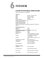
Eclipse PiCo Technical Specification . . . . . . . . . . . . . . . . . . . . . . . . 6-1
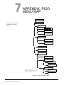
APPENDIX: PICO MENU MAP . . . . . . . . . . . . . . . . 7-1
GLOSSARY . . . . . . . . . . . . . . . . . . . . . . . . . . . . . . . 8-1
Eclipse Manuals . . . . . . . . . . . . . . . . . . . . . . . . . . . . . . . . . . . . . . . . 8-5
Software Manuals . . . . . . . . . . . . . . . . . . . . . . . . . . . . . . . . . . . . . 8-5
Hardware Manuals . . . . . . . . . . . . . . . . . . . . . . . . . . . . . . . . . . . . 8-5
LIMITED WARRANTY . . . . . . . . . . . . . . . . . . . . . . . W-I
TECHNICAL SUPPORT & REPAIR POLICY. . . . . W-V
TECHNICAL SUPPORT POLICY . . . . . . . . . . . . . . . . . . . . . . . . . . W-v
RETURN MATERIAL AUTHORIZATION POLICY . . . . . . . . . . . . . W-vi
REPAIR POLICY . . . . . . . . . . . . . . . . . . . . . . . . . . . . . . . . . . . . . W-viii
Clear-Com Communication Systems
Eclipse PiCo Matrix Instruction Manual
iii
iv
Clear-Com Communication Systems
Eclipse PiCo Matrix Instruction Manual
IMPORTANT SAFETY INSTRUCTIONS
Please read and follow these
instructions before operating
this product.
1. Read these instructions.
2. Keep these instructions.
3. Heed all warnings.
4. Follow all instructions.
5. Do not use this apparatus near water.
6. Clean only with dry cloth.
7. Do not block any ventilation openings. Install in accordance with the
manufacturer’s instructions.
8. Do not install near any heat sources such as radiators, heat
registers, stoves, or other apparatus (including amplifiers) that
produce heat.
9. Do not defeat the safety purpose of the polarized or grounding-type
plug. A polarized plug has two blades, with one wider than the other.
A grounding-type plug has two blades and a third grounding prong.
The wide blade or the third prong are provided for your safety. If the
provided plug does not fit into your outlet, consult an electrician for
replacement of the obsolete outlet.
10. Protect the power cord from being walked on or pinched
particularly at plugs, convenience receptacles, and the point where
they exit from the apparatus.
11. Only use attachments/accessories specified by the manufacturer.
12. Use only with the cart, stand, tripod, bracket, or table specified by
the manufacturer, or sold with the apparatus. When a cart is used,
use caution when moving the cart/apparatus combination to avoid
injury from tip-over.
13. Unplug this apparatus during lightning storms or when unused for
long periods of time.
14. Refer all servicing to qualified service personnel. Servicing is
required when the apparatus has been damaged in any way, such
as power-supply cord or plug is damaged, liquid has been spilled or
objects have fallen into the apparatus, the apparatus has been
exposed to rain or moisture, does not operate normally, or has been
dropped.
15. WARNING: To reduce the risk of fire or electric shock, do not
expose this product to rain or moisture.
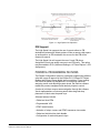
Please familiarize yourself with the safety symbols in Figure 1.
When you see these symbols on this product, they warn you of
the potential danger of electric shock if the main station is used
improperly. They also refer you to important operating and
maintenance instructions in the manual.
Clear-Com Communication Systems
Eclipse PiCo Matrix Instruction Manual
i
CAUTION
RISK OF ELECTRIC SHOCK
DO NOT OPEN
This symbol alerts you to the presence of uninsulated dangerous
voltage within the product's enclosure that might be of sufficient
magnitude to constitute a risk of electric shock. Do not open
the product's case.
This symbol informs you that important operating and maintenance instructions are included in the literature accompanying
this product.
Figure ii-1: Safety Symbols
EMC AND SAFETY
The Eclipse PiCo matrix meet all relevant CE, FCC, UL, and CSA
specifications set out below:
EN55103-1 Electromagnetic compatibility. Product family
standard for audio, video, audio-visual, and entertainment
lighting control apparatus for professional use. Part 1:
Emissions.
EN55103-2 Electromagnetic compatibility. Product family
standard for audio, video, audio-visual, and entertainment
lighting control apparatus for professional use. Part 2: Immunity.
UL 60065-7, CAN/CSA-C22.2 No.60065-3, IEC 60065-7 Safety
requirements.
And thereby compliance with the requirement of Electromagnetic
Compatibility Directive 2004/108/EC and Low Voltage Directive
2006/95/EC
This device complies with Part 15 of the FCC Rules. Operation is
subject to the following two conditions: (1) this device may not
cause harmful interference, and (2) this device must accept any
interference received, including interference that may cause
undesired operation.
ii
Clear-Com Communication Systems
Eclipse PiCo Matrix Instruction Manual
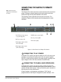
1
The Eclipse PiCo digital
matrix intercom features 32
full-duplex communications
ports, plus four 4-wire ports.
The matrix fits in one rack
unit (1 RU) of a standard
Electronic Industry
Association equipment rack.
INTRODUCTION
THE ECLIPSE PICO MATRIX
The Eclipse family of communications products includes the Eclipse
PiCo digital matrix intercom, which offers 32 full-duplex communication
ports, plus four extra 4-wire ports, in a one rack unit (1 RU) chassis.
The Eclipse PiCo matrix supports the same V-Series panels,
i-stations, 4000 series panels, ICS digital matrix panels and interfaces
as its larger counterparts, the Eclipse Omega and Median matrices,
and is programmed and controlled with the same Eclipse Configuration
System (ECS) software.
Two Eclipse PiCo matrices can be joined together to form an
intelligently linked non-blocking 64-port system in two rack units (2 RU)
using a single RJ-45 “base loop” connection. The Eclipse PiCo matrix
also provides two power supplies for fail-safe redundancy, and
onboard general-purpose inputs and outputs.
The Eclipse PiCo matrix is built around the powerful Motorola 8260
processor, giving it the same processing power as the larger Eclipse
Omega matrix.
This manual refers to facilities in the Eclipse 4.2 software release.
Features of the Eclipse PiCo matrix include:
• Thirty-six ports in one rack unit (1 RU), including four 4-wire ports
• Eight onboard relays and eight onboard GPIs
• Non-blocking 64-port system created by connecting two matrices with
the high-speed link
• Intelligent linking of up to 15 matrices using the 4-wire trunks and a
LAN
• Two power supplies for fail-safe redundancy
• Seamless interfacing
• DTMF inward access
• Programmable VOX
• Individual level control
• Intuitive ECS programming software
• Remote matrix access via Internet/Ethernet
• Frequency response of 30 Hz to 22 kHz, ± 3 dB
• SNR and crosstalk > -70 dB
Clear-Com Communication Systems
Eclipse PiCo Matrix Instruction Manual
1-1
INTELLIGENT LINKING
An intelligent link may be used to connect an Eclipse PiCo to other
Eclipse-32, Eclipse Pico, Eclipse Median or Eclipse Omega matrices.
Up to 15 matrices may be connected. The linking between matrices is
via dedicated trunk lines between ports on the linked systems.
This capability is in addition to the high-speed link which connects two
Eclipse PiCo matrices into one non-blocking 64-port system subject to
the condition described below.
Two Eclipse PiCo matrices that are connected using a high-speed link
cannot also be connected together with a trunk line. In this case trunk
lines should only be used to connect such Eclipse PiCo systems to
other matrices.
Any port within the matrix may be used as a trunk line, and carries one
full-duplex communications path between the matrices. Typically the
number of trunk lines would equal the anticipated simultaneous
communications between matrices. The system will intelligently use
and release these lines to route the communications traffic between
panels connected with the various matrices, routing the calls through
available open trunks.
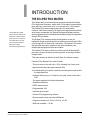
HIGH SPEED LINK
A high speed link is used to connect two Eclipse PiCo matrices
together via the Base Loop Connector to create a 64-port non-blocking
system. The high speed link operates by ‘mapping’ the physical ports
(0-35) of the remote system onto a second set of virtual ports on the
local system (36-71). A panel on the local system can listen to a panel
on the remote system simply by listening to the virtual port for that
panel.
If a panel on the remote system opens a talk path to a panel on the
local system a message is sent via the link instructing the local system
to create the required audio path from the remote system to the local
panel.
The ethernet link is required to pass key labels between the systems
as well as receive configuration data from ECS.
A diagram of High Speed Link operation is shown in Figure 1-1.
1-2
Clear-Com Communication Systems
Eclipse PiCo Matrix Instruction Manual
Figure 1-1: High Speed Link Operation
IFB Support
The High Speed Link supports the use of remote callers to IFB
destinations between the linked systems. When a remote caller opens
an audio path to an IFB destination the source for that IFB will be
dimmed as normal.
The High Speed Link will support the use of Local IFB where
Assignment Panels can assign sources to an IFB locally. This option
may be enabled in ECS (Advanced Settings > AP Panel Options > IFB
Assignment).
POWERFUL PROGRAMMING FEATURES
The Eclipse Configuration System is a powerful programming software
suite that covers all aspects of the Eclipse PiCo, Eclipse-32, Eclipse
Median and Eclipse Omega digital intercom matrices. From creating
user labels for panel key assignments, to configuring interfaces,
assigning routes, and adjusting system levels, the intuitive software
makes the process transparent and relatively simple to control.
A series of pull-down menus eases navigation through the software.
Visual representations of intercom panels allow drag-and-drop
placement of labels onto the panel keys.
Software features include:
• Global and local IFBs
• Programmable VOX
• DTMF inward access
• Activation of relays, routes, and DTMF sequences via controls
• Global and individual key latch disable
• Configuration of matrix and panel relays
Clear-Com Communication Systems
Eclipse PiCo Matrix Instruction Manual
1-3
NOTE: The term
“central matrix” is used
to differentiate the
system’s core hardware
and software from the
connected intercom
panels and interfaces.
The central matrix itself
consists of the matrix
hardware and
configuration software.
• Forced listens (normally made routes)
• Port I/O level control
• Local and global ISO routes
• Control labels
The Eclipse PiCo matrix allows TCP/IP access to the system for
updates. The system may be accessed remotely for programming or to
retrieve configurations. Up to four full-system configurations may be
stored in the Eclipse PiCo matrix, and an unlimited number of
configurations may be backed up on a computer and downloaded to
the matrix as needed.
INDIVIDUAL LEVEL CONTROL
Both incoming and outgoing volume levels can be adjusted for each
device connected to an Eclipse PiCo port, which allows the Eclipse
PiCo to be connected to a wide variety of panels and communications
devices either directly via the port or via interfaces. On the panels,
individual listen-level controls allow the operator to adjust the level of
each key to provide a customized audio “mix”.
EXCELLENT AUDIO QUALITY
The Eclipse PiCo matrix features industry-leading 24-bit, 48 kHz audio
sampling, yielding a frequency response of 30 Hz to 22 kHz, ± 3 dB.
With a signal-to-noise ratio better than –70 dB, and crosstalk better
than –70 dB, the audio among panels, interfaces, and other system
inputs and outputs is clean and distinct. Level adjustments are in
0.355 dB steps, which will sound completely smooth to the user.
ROBUST AND COMPATIBLE
The Eclipse PiCo matrix houses two independent power supplies.
These may be connected to a main and backup power source for
redundancy. In the unlikely event of the failure of one of these power
supplies, the second supply will automatically take over. The Eclipse
PiCo is robust even in the face of a major power outage. In the event of
a complete power interruption, the system will return with all previously
set talk and listen paths in place when power is restored.
The Eclipse PiCo matrix is fully compatible with Clear-Com’s modular
matrix interface modules and frames. It can transparently interface
with telephones, two-way radios, camera and 2-wire intercoms, 4-wire
devices, and audio sources. Eclipse PiCo is also compatible with most
of the matrix intercom panels, including the V-Series, ICS-92,
ICS-2003, 4000 series, and i-stations.
1-4
Clear-Com Communication Systems
Eclipse PiCo Matrix Instruction Manual
ECLIPSE PICO APPLICATIONS
The Eclipse PiCo is the perfect solution for high-quality full-duplex
communications requiring a moderate number of ports in a compact
1-RU form. With the ability to intelligently link two Eclipse PiCo
matrices together, tasks such as mobile production, small to mid-sized
studio integration, and sports and performing facilities communications
are easily realized. Intelligent linking to other Eclipse PiCo and Eclipse
Omega matrices adds to its ability to be the core of a comprehensive
communications system.
SYSTEM BASICS
A complete Eclipse PiCo system consists of a central matrix and the
remote audio devices—intercom panels, interfaces, 4-wire
equipment—connected to it. Each element of the Eclipse PiCo system
is briefly described in this chapter and more fully described later in this
manual and in the Eclipse set of manuals.
The Eclipse set of manuals includes the overview manual Eclipse
Matrix Installation Manual (part 810298Z), as well as individual
manuals for each matrix, panel, and interface in the system.
MATRIX HARDWARE
The Eclipse PiCo matrix is 19 inches wide and one rack unit high (26.9
cm x 48.3 cm). It installs in a standard Electronics Industry Association
equipment rack. No parts of the unit are removable without it being
taken out of service.
The matrix’s front panel provides pushbuttons and indicator lights for
operating the system, while the back panel holds the RJ-45
connectors, or “ports,” for connecting remote intercom panels and
interfaces to the system. The next chapter describes the matrix’s
operation in more detail.
Note: The term “central matrix” is used to differentiate the
system’s core hardware and software from the connected
intercom panels and interfaces. The central matrix itself
consists of the matrix hardware and configuration software.
POWER SUPPLIES
An Eclipse PiCo matrix has two internal power supply units. One power
supply unit can power the entire matrix; the second unit provides a
backup in case of failure or damage to the first unit.
In addition, the two supplies have separate IEC connectors to AC
mains, and are designed for completely automatic and transparent
changeover between supplies in the event of a power outage in one of
the AC mains circuits.
Clear-Com Communication Systems
Eclipse PiCo Matrix Instruction Manual
1-5
A power-supply failure sensor is connected to a warning light, allowing
power anomalies to be diagnosed.
REAR-PANEL CONNECTORS (“PORTS”)
The Eclipse PiCo matrix connects to remote devices such as intercom
panels, interfaces, general purpose inputs and outputs, local area
networks, and other matrices through its rear-panel hardware
connectors.
A rear-panel RJ-45 connector to which cable is connect to run from the
matrix to a panel or interface is called a “port”. Shielded category-5
cable is connected to a “port” to carry signals from the Eclipse PiCo
matrix to connected remote intercom panels or interfaces. Later
chapters of this manual discuss these connections in detail.
ECLIPSE CONFIGURATION SOFTWARE (ECS)
The Eclipse Configuration System (ECS) software controls the
operation of the matrix by sending electronic signals to the Eclipse
PiCo matrix, which then relays the signals to the remotely connected
panels and interfaces.
“Configuration Maps”—which are the operating parameters of
complete system setups can be created on the ECS computer. The
Eclipse Configuration System programming software stores the
created configurations on the computer’s hard disk using a relational
database which holds up to two gigabytes of configuration data and is
able to store over 100,000 complex system configurations. ECS can
then upload four complete configurations from the computer to the
Eclipse-32 matrix’s operational memory to retrieve and activate directly
from the matrix when needed.
The Eclipse Configuration System software runs on the following
versions of Windows: Windows 2000, Windows XP, Windows Server
2003 and Windows Vista (with restrictions). When running ECS on
Windows operating systems, the client and server can run on separate
machines connected over a network.
The Eclipse Configuration System can be used to create point-to-point
and fixed group or party-line communications among the connected
remote audio devices, assign a “label” to each port/panel, and inhibit or
enable features at any connected remote panel. The Eclipse
Configuration System can be set up to run on a client/server model
over a network allowing the matrix to be controlled remotely.
1-6
Clear-Com Communication Systems
Eclipse PiCo Matrix Instruction Manual
REMOTE INTERCOM PANELS AND ACCESSORY
PANELS
All analog intercom panels connect to the central matrix via shielded
category-5 cable terminated with RJ-45 connectors. Digital panels
connect to the central matrix through AES-6 or DIG-2 digital module
interfaces. Digital panels require double-shielded 24 AWG conductor
category-6 enhanced (CAT-6E) cable to connect to a DIG-2 interface
or coaxial cable to connect to the AES-6-CX rear card. For further
details on connecting digital panels to the Eclipse PiCo please refer to
the appropriate product manual.
The following intercom panels are compatible with the Eclipse PiCo
matrix system:
• i-Station family, including expansion panels
• ICS-2003 intercom panel, including expansion panels
• ICS-52 and ICS-92 intercom panels, including expansion panels
• ICS-62 and ICS-102 intercom panels, including expansion panels
• ICS-1008 and ICS-1016 intercom panels, including expansion
panels
• ICS-21/22/24 intercom panels
• 4215E, 4224E, 4226E, 4212E, 4222E, 4294E, 4203E, 4206E,
4230E and 4230VE 4000 Series II panels
• V12LD, V24LD, V12PD, V24PD, V12LDD, V12PDD, V12LDE and
V12PDE V-Series panels
Each of these panels is described in its own manual. For a full
description of the operation, installation and maintenance of a panel,
please refer to the appropriate panel manual.
Clear-Com Communication Systems
Eclipse PiCo Matrix Instruction Manual
1-7
REMOTE INTERFACES
Interface modules convert the 4-wire signals of a central matrix port to
other types of signals that communicate with devices such as
telephones, camera intercoms, two-way radios, and so on. In this way
non-4-wire devices can communicate with the central matrix.
Each interface module has hardware connectors to connect to both the
central matrix and to the external device that communicates with the
central matrix. Most interface modules connect to the central matrix via
shielded category-5 cable terminated with RJ-45 connectors. The
DIG-2 digital interface module, however, connects to the central matrix
via double-shielded 24 AWG conductor category-6 enhanced
(CAT-6E) STP cable.
The type of cable used to connect the interface module to the
non-4-wire device varies with the device. Each of these connections is
described more fully in the individual manual for each interface.
The following interface modules are compatible with the Eclipse PiCo
matrix:
• TEL-14 telephone interface module
• CCI-22 dual party-line interface module
• FOR-22 four-wire interface module
• GPI-6 general purpose inputs interface module
• RLY-6 relay (general-purpose outputs) interface module
• AES-6 digital interface module
• DIG-2 digital interface module (transparent to the system,
configured in ECS as the type of panel it is connected to)
Each of these interfaces is described in its own manual. For a full
description of the operation, installation, and maintenance of an
interface, refer to the individual manual for that interface.
1-8
Clear-Com Communication Systems
Eclipse PiCo Matrix Instruction Manual
2
A configuration map is
created with the Eclipse
Configuration System (ECS)
programming software.
OPERATING AN
ECLIPSE PICO
MATRIX
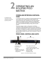
STORING AND RETRIEVING CONFIGURATIONS
A “configuration map” is a complete set of operating parameters for the
matrix system which includes all talk and listen paths for each
connected intercom panel. Depending upon the remote interfaces
installed, the configuration can also include more sophisticated
features such as paging, call signaling, interruptible foldback (IFB),
ISO, groups, automatic DTMF dialing, routing, and many other
features.
The system manager creates a configuration in the Eclipse
Configuration System programming software and then uploads the
configuration to the Eclipse PiCo matrix’s operational memory through
the software. The Eclipse PiCo matrix’s operational memory holds up
to four complete configurations. From the controls on the matrix’s front
panel the system manager may select which configuration to apply at
any given time.
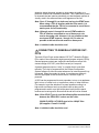
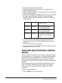
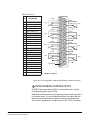
FRONT-PANEL CONTROLS AND LIGHTS
2 4
1
3
8
6
5
7
9
1 Connector to PC
2 Reset Button
3 OK Light
4 Configuration button for
selecting among onboard
configurations
5 Status lights which show
currently active configuration
6 Power supply alarm lights (1 and 2)
7 LAN status lights
8 Display window
9 Setup/enter knob
Figure 2-1: Front Panel of Eclipse PiCo Matrix
Clear-Com Communication Systems
Eclipse PiCo Matrix Instruction Manual
2-1
1
PC CONNECTOR
The female 3.5 mm jack socket labeled “RS-232” connects the matrix
to an external computer. See the Installation Chapter for information on
wiring this connection.
2
RESET BUTTON
Pressing the reset button causes the matrix to stop its current activity
and to restart. The same configuration that was active before the
matrix was reset will be active after it is reset.
During the reset, configuration information reloads to the matrix’s
operational memory from its non-volatile memory and the matrix starts
running again from the beginning.
3
OK LIGHT
When flashing, the “OK” light indicates that the Eclipse PiCo matrix is
running normally.
4
CONFIGURATION “CONFIG” BUTTON
The Eclipse PiCo matrix can hold four complete system configurations
in its operational memory. Any one of the four configurations can be
activated using the CONFIG button on the matrix front panel.
When one of the four configurations is active, its front-panel light
illuminates steadily.
Note: A configuration can also be selected using the setup/enter
knob and front-panel display. See page 3-6 for more
information.
To select a new configuration
1. Repeatedly tap the CONFIG button until the desired configuration’s
light (1,2,3, or 4) starts flashing.
2. While the desired configuration’s light flashes, press and hold the
configuration button for three seconds, until the light stops flashing,
and illuminates steadily.
The selected configuration then becomes the system’s active
operational configuration.
If an invalid or blank configuration is chosen all four configuration lights
steadily illuminate at the same time for about a second. The currently
active configuration will continue to operate and its front-panel light
steadily illuminates after the other lights go out.
2-2
Clear-Com Communication Systems
Eclipse PiCo Matrix Instruction Manual
5
CONFIGURATION STATUS LIGHTS
The four configuration status lights indicate which of the four onboard
configurations is currently active. The currently active configuration’s
light illuminates steadily.
6
POWER SUPPLY ALARM LIGHTS (1 AND 2)
An Eclipse PiCo matrix has two internal power supply units. One power
supply unit can power an entire matrix; the second unit provides a
backup in case of an equipment failure.
In addition, the two supplies have separate IEC connectors to AC
mains power, and are designed for completely automatic and
transparent changeover between supplies in the event of an outage on
one of the AC mains circuits.
The front-panel alarm lights do not illuminate under normal operating
conditions.
The following conditions cause a power-supply alarm light to
illuminate:
• If any of the voltages produced by the first power supply unit fall
below normal levels.
• If any of the voltages produced by the second power supply unit fall
below normal levels.
Once the power-supply fault condition is no longer present, the
power-supply alarm light goes out.
7
LAN STATUS LIGHTS
When a local area network is connected to the matrix’s LAN port, the
LAN UP light steadily illuminates to indicate that the Eclipse PiCo
matrix is connected to a local area network. The Rx light flashes when
data is being received.
Note also that the PiCo’s front-panel System Status screen shows
activity when a LAN is connected and communicating with the matrix.
8
DISPLAY WINDOW
Using the display window and setup/enter knob a variety of actions can
be performed directly from the PiCo matrix, without any need for the
Eclipse Configuration System programming software. See the chapter
“Using the PiCo’s Front Panel Display Menus” in this manual for more
information.
Clear-Com Communication Systems
Eclipse PiCo Matrix Instruction Manual
2-3
9
SETUP/ENTER KNOB
The setup/enter knob is used in conjunction with the display window
(see above) to perform a variety of actions directly from the PiCo
matrix, without any need for the Eclipse Configuration System
programming software. See the chapter “Using the PiCo’s Front Panel
Display Menus” in this manual for more information.
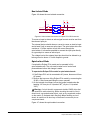
DEFAULT IP ADDRESS
From Eclipse 4.2 release onwards a factory default IP address
(172.16.2.100) is set up in the matrix firmware which will always be
available via an IP reset. This ensures that once the matrix firmware is
loaded it will always be possible to access the matrix via ethernet even
if the current IP address is not known.
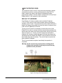
To carry out an IP reset it is necessary to remove the cover of the
Eclipse PiCo in order to access the three reset switches positioned at
the front left of the main circuit board (viewed from the front of the unit)
shown in Figure 2-2. To carry out an IP reset press and hold the
rightmost two switches (nearest the side of the case) simultaneously
and then press and release the ‘RESET’ button at the front of the unit,
then release the internal switches. The unit will then be reset to the
factory default IP address.
The unit cover should be replace immediately the operation is
completed.
Warning: As the unit must be powered when resetting the IP
address this operation should only be carried out by
qualified service personnel.
Figure 2-2: Eclipse PiCo Reset Buttons
2-4
Clear-Com Communication Systems
Eclipse PiCo Matrix Instruction Manual
Note: General Purpose
Outputs are also referred to
as “relays.”
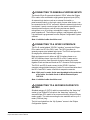
CONNECTING THE MATRIX TO REMOTE
DEVICES
The Eclipse PiCo matrix connects to remote devices such as intercom
panels, interfaces, general purpose inputs and outputs, and other
matrices through its rear-panel hardware connectors.
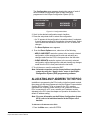
The following sections describe the rear-panel connectors. The
Installation Chapter of this manual gives pin assignments for each
connector.
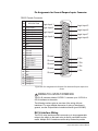
2
1
1 Two IEC AC power input connectors,
(1 per power-supply unit )
3
5
4
6
7
5 GPI/RLY interface connector (RJ-45)
6 Base loop connector (RJ-45)
2 RJ-45 port connectors (36)
7 LAN connector (RJ-45)
3 General purpose outputs connector
(male, 25-pin, D-type)
4 General purpose inputs connector
(female, 25-pin, D-type)
Figure 2-3: Rear Panel of an Eclipse PiCo Matrix
1 CONNECTING TO AC POWER
An Eclipse PiCo matrix’s rear panel contains two IEC AC power input
sockets for connecting AC mains power to the two power supplies.
Each IEC socket connects cable to one power supply, operating at an
input voltage of 100 to 240 volts, between 50 and 60 hertz.
2 CONNECTING TO PANELS AND INTERFACES
An Eclipse PiCo matrix’s rear panel contains 36 RJ-45 sockets for
connecting the matrix to remote intercom panels and interfaces. These
sockets are often called “ports”. Each port socket is given a number on
the rear-panel for easy identification.
All ports contain a voice detection mechanism (“VOX”) that is
programmed from the Eclipse Configuration System software. VOX
Clear-Com Communication Systems
Eclipse PiCo Matrix Instruction Manual
2-5
detection allows the panel operator to know when the audio on a
particular channel has exceeded a threshold. This is particularly useful
for channels that are inactive periodically, so that the panel operator is
visually cued in the software when audio appears on the line.
Note: Ports 17 through 32 can both send and receive DTMF tones.
When using a TEL-14 interface with the PiCo matrix, it is
recommended that the TEL-14 is connected to one of these
matrix ports for full functionality.
Note: Although ports 1 through 16 are not DTMF-enabled, a
TEL-14 interface connected to one of these ports can
receive incoming calls. However it is not possible to then
use inward DTMF on ports 1 though 16. It is also not
possible to dial out from the matrix on these ports.
Note: A shielded cable should be used.
3 CONNECTING TO GENERAL-PURPOSE OUT-
PUTS
The male 25-pin D-type socket labeled “GP OUT” allows the Eclipse
PiCo matrix to be connected to eight general purpose outputs (GPOs).
General-purpose outputs are single-pole double-throw relays with
contact ratings of 30 VDC (volts direct current) at 1 ampere.
A general purpose output or “relay” is a switch that is controlled
remotely. The relay is programmed in the Eclipse Configuration
System software to close a contact whenever an intercom panel’s key
is pressed. When the contact is closed, it completes an electronic
circuit’s signal path so that a remote device, such as a light, is
powered.
A GPO can be programmed to mute a speaker, to turn on an applause
light, to turn on a door lock, or to perform a variety of other functions.
For example, to get the attention of a panel operator working in a
high-noise environment such as a control booth a relay can be
programmed to switch on a light at the panel each time the panel
receives an incoming call to ensure that the call will not be missed.
Note: If the GP-OUT port is used the following filter must be fitted
between the PROC-RCC socket and the cable:
CINCH FA-25PS/1-LF 25W D-type in-line 1000pF filter
(UK supplier: Farnell 111-4108)
Note: A shielded cable should be used.
2-6
Clear-Com Communication Systems
Eclipse PiCo Matrix Instruction Manual
4 CONNECTING TO GENERAL-PURPOSE INPUTS
The female 25-pin D-type socket labeled “GP IN” allows the Eclipse
PiCo matrix to be connected to eight general purpose inputs (GPIs).
An external logic device–such as an external foot switch, a
panel-mounted switch, or the logic output of some other device– can
be connected to the “GP IN” connector. When the external logic device
is activated, it sends a control signal into the matrix to perform one of
several preset functions, such as turning an intercom panel’s
microphone on or off, muting a microphone’s output, or turning a
panel’s speaker off. The function to perform, and the panel upon which
it is performed is programmed from the Eclipse Configuration System
software.
Note: A shielded cable should be used.
5 CONNECTING TO A GPI/RLY INTERFACE
The RJ-45 socket labeled “GPI/RLY Interface” connects the Eclipse
PiCo matrix to a GPI-6 or RLY-6 card. The GPI-6 provides six
general-purpose opto-isolated logic inputs. The RLY-6 card provides
six single-pole, double-throw relay outputs.
Both card types mount in either an IMF-3 interface frame or an
IMF-102 interface frame. Up to ten GPI-6 or RLY-6 cards can be
operated at one time from the matrix by daisy-chaining the cards
together. Each card has an IN and an OUT connector for this purpose.
The RLY-6 and GPI-6 cards connect to the GPI/RLY interface
connector using shielded category-5 cable. For more information about
the GPI-6 and RLY-6 cards, consult their respective manuals.
Note: If this port is used a ferrite must be added to the socket end
of the cable. A suitable ferrite is Würth Electronik part:
74271132.
Note: A shielded cable should be used.
6 CONNECTING TO A SECOND ECLIPSE PICO
MATRIX
Shielded category-5 (CAT-5) cable is connected from the “base loop”
socket of one Eclipse PiCo matrix to the “base loop” socket of a
second Eclipse PiCo matrix to form one non-blocking 64-port Eclipse
matrix system. The cable connecting the two matrices can be up to 1
meter (3.28 feet) long.
The link is activated from the “My Systems” screen in the Eclipse
Configuration System.
Clear-Com Communication Systems
Eclipse PiCo Matrix Instruction Manual
2-7
Note: To transfer data between two linked PiCo matrices using
the high-speed link the Ethernet ports must be connected
with either a cross-over shielded CAT-5 cable or a with a
hub or switch using conventional shielded CAT-5 cable.
7 CONNECTING TO A LOCAL AREA NETWORK
The RJ-45 socket labeled “LAN” connects a local area network (LAN)
to the Eclipse PiCo matrix through a standard Ethernet connection.
Note: If this port is used a ferrite must be added to the socket end
of each cable. A suitable ferrite is Würth Electronik part:
74271132.
Note: A shielded CAT-5 cable should be used.
2-8
Clear-Com Communication Systems
Eclipse PiCo Matrix Instruction Manual
3
The system operator can get
information or select system
options using the PiCo’s
front-panel menus.
USING THE PICO
FRONT PANEL
MENUS
Using just the front-panel controls and display menus the system
operator can perform a variety of actions directly from the PiCo matrix,
without any need for the Eclipse Configuration System (ECS)
programming software. For example the system operator can:
• Check whether a connected panel is online and communicating with
the matrix
• Adjust incoming and outgoing audio levels for a panel connected to
the matrix
• Create audio routes between audio devices connected to the PiCo
matrix
Scroll to an item by turning
the setup/enter knob. Select
an item by pressing the knob
in, as if it were a pushbutton.
• Select and activate one of the four available onboard configuration
maps
• Allocate an IP address to the matrix so that it can operate on a
network
• Access information about system number and firmware version
• Access status of high-speed link and local area connection
• Select a source and destination of Identification Tone
• Reset the system to apply locally made changes
• Check whether or not general purpose inputs and outputs are on
• Switch general purpose outputs on and off
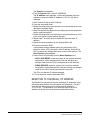
STARTING FROM THE MAIN MENU
When the system is first powered up the “Clear-Com Eclipse PiCo”
screen appears. When the setup/enter knob is pressed the main menu
appears, as shown in Figure 3-1.
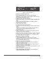
MAIN MENU
STATUS
AUDIO
EXIT
ROUTING
CONFIGS SYSTEM
Figure 3-1: Main Menu
Clear-Com Communication Systems
Eclipse PiCo Matrix Instruction Manual
3-1
“Source” refers to a
device—beltpack, intercom
panel, or a variety of other
devices—from which audio is
received.
Scroll to a menu item by rotating the setup/enter knob. When the
desired menu item is highlighted on the screen, select it by pressing
the setup/enter knob.
Note: The PiCo display dims when the unit has not been used for
three minutes. Pressing any key causes the previously
displayed screen to reappear.
CHECKING PORT STATUS
“Destination” refers to a
device to which audio is sent.
Scrolling to and selecting Status on the Main menu causes the Status
menu to appear providing further options.
STATUS MENU
EXIT
PORTS
GPI
GPO
Figure 3-2: Status Menu
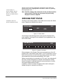
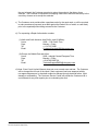
On scrolling to and selecting Ports on this menu the System Ports
menu appears, showing all of the available 36 ports graphically, with
their current status.
SYSTEM PORTS
P
N
EXIT
Figure 3-3: System Ports Menu
Each rectangle on the System Ports menu represents one of the 36
possible “port” connections in the system. A “port” connection is one of
the RJ-45 connectors on the PiCo’s rear panel to which remote panel
and interfaces are connected with shielded CAT-5 cable.
When a remote device is connected to a PiCo “port,” the rectangle will
first show a chequered pattern to indicate communications activity,
then will change to a solid light when the connected device is online
and communicating with the matrix.
In addition, a letter or number will appear above each rectangle to
indicate the type of connection, as follows:
3-2
Clear-Com Communication Systems
Eclipse PiCo Matrix Instruction Manual
CODE
DESCRIPTION
R
2-way radio
4
4-wire audio
P
panel
N
4-wire network
trunk
T
telephone
Table 3-1: Port Functions
Note: Ports 33 through 36 do not show the chequered pattern to
indicate communications activity, but will light solidly to
indicate an online connection to the matrix. In addition, a
letter or number will appear on the display above these port
symbols to indicate port function.
ADJUSTING AUDIO LEVELS
Both incoming and outgoing audio levels can be adjusted for an audio
device (intercom panel, interface, and so on) connected to a PiCo port.
To adjust audio levels for a device connected to a PiCo port
1. From the Main menu, select AUDIO.
The Audio menu appears, as shown in Figure 3-4.
2. From the Audio menu, select either INPUTS or OUTPUTS.
From the Input Level menu the incoming volume level to a port can
be adjusted. From the Output Level menu the outgoing volume
level from a port can be adjusted.
AUDIO MENU
INPUTS
EXIT
OUTPUTS
CLEAR TONES
Figure 3-4: Audio Menu
EXIT
INPUT LEVEL
PORT { 00 } [
LEVEL { -0 } dB
]
Figure 3-5: Input Level Menu
Clear-Com Communication Systems
Eclipse PiCo Matrix Instruction Manual
3-3
OUTPUT LEVEL
PORT { 00 } [
LEVEL { -0 } dB
]
EXIT
IDENT TONE:
Enable [ ]
Figure 3-6: Output Level Menu
To adjust a port’s incoming audio levels
1. From the Input Level menu, scroll to the PORT number.
When a port number appears onscreen, that port’s label, as set in
ECS, automatically appears next to it.
2. Press and release the setup/enter knob.
3. Rotate the setup/enter knob clockwise to display the available port
digits.
4. When the desired port digit appears in the display, press the
setup/enter knob to select it.
5. Scroll to the LEVEL number.
6. Press and release the setup/enter knob.
7. Rotate the setup/enter knob clockwise to display available decibel
levels.
The audio level changes in real time as the setup/enter knob is
rotated in the same way as adjusting the audio with a
volume-control knob.
8. When the desired decibel level appears in the display, press the
setup/enter knob to select and save it.
The audio level can be set between -60 dB and 18 dB in 1 dB steps.
9. To exit the menu, scroll to and select EXIT, or to adjust another
port’s level repeat steps 1 through 8.
To adjust a port’s outgoing audio levels
1. From the Output Level menu, scroll to the PORT number.
When a port number appears onscreen, that port’s label, as set in
ECS, automatically appears next to it.
2. Press and release the setup/enter knob.
3. Rotate the setup/enter knob clockwise or counterclockwise to
display the available port digits.
4. When the desired port number appears in the display, press and
release the setup/enter knob to select it.
5. Rotate the setup/enter knob clockwise or counterclockwise to scroll
to the LEVEL number.
6. Press and release the setup/enter knob.
7. Rotate the setup/enter knob clockwise or counterclockwise to
display available decibel level values.
3-4
Clear-Com Communication Systems
Eclipse PiCo Matrix Instruction Manual
The audio level changes in real time as the setup/enter knob is
rotated in the same way as adjusting the audio with a
volume-control knob.
8. When the desired digit appears in the display, press and release the
setup/enter knob to select and save it.
The audio level can be set between -60 dB and 18 dB in 1 dB steps.
9. To set the port’s audio source as Identification Tone, scroll to and
select the Ident Tone Enable checkbox. To turn off the Identification
Tone, clear the checkbox.
• The Identification Tone (Ident Tone) is typically sent to destinations
that require a tone or audio statement during system setup.
• The Identification Tone continues until either the ENABLE
checkbox is cleared or CLEAR TONES is selected in the Audio
menu.
• The source of the Identification Tone is selected from the
Maintenance menu. See “Selecting a Source of Identification
Tone” later in this chapter.
10. To exit the menu, scroll to and select EXIT, or to adjust another
port’s audio level, repeat steps 1 through 8.
CREATING AUDIO ROUTES
An audio route between a source and a destination can quickly and
easily be created directly from the PiCo’s front panel.
To create an audio route
1. From the Main menu, select ROUTING.
The Routes menu appears.
ROUTES
SOURCE 00
DESTINATION 00
ENABLE [X]
SAVE
[SRC LABEL]
[DST LABEL]
INHIBIT [X]
EXIT
Figure 3-7: Routes Menu
Note: When a port number is selected on the screen, that port’s
label, as set in ECS, automatically appears.
2. Scroll to the Source number.
3. Press and release the setup/enter knob.
4. Rotate the setup/enter knob clockwise or counterclockwise to
display available port digits.
5. When the desired digit appears in the display, press the setup/enter
knob to select and save it.
6. Scroll to the Destination number.
Clear-Com Communication Systems
Eclipse PiCo Matrix Instruction Manual
3-5
7. Press and release the setup/enter knob.
8. Rotate the setup/enter knob clockwise or counterclockwise to
display available port digits.
9. When the desired digit appears in the display, press the setup/enter
knob to select and save it.
10. Select either the Enable or Inhibit check boxes to enable or inhibit
the audio route between the selected Source and Destination.
The following table shows the possible selections for inhibiting or
enabling a route.
Inhibit [ ]
Enabled [ ]
No control of selected route
made via screen
Inhibit [X]
Enabled [ ]
Routes blocked between
source and destination
Inhibit [ ]
Enable [X]
Routes enabled between
source and destination
Inhibit [X]
Enable [X]
Not allowed. It is not possible
to both inhibit and enable a
route.
Table 3-2: Possible Settings for Inhibiting and Enabling Routes
11. Scroll to and select SAVE by pressing the setup/enter knob.
(Leaving this screen without selecting SAVE cancels all selected
route data.)
The route confirmation screen appears.
12. To confirm the route, scroll to and select YES. To back out from the
changes select either NO or EXIT.
SELECTING AND ACTIVATING A CONFIGURATION
Each PiCo matrix can store up to four complete configuration maps in
its onboard memory. A “configuration” is a complete set of operating
parameters for the matrix system which includes all talk and listen
paths for each connected intercom panel. A configuration map is
created and named in the Eclipse Configuration System programming
software.
Any of these maps can be selected and activated directly from the
PiCo. First select the configuration map to apply. Then when the
system is reset the selected configuration map goes into effect
immediately.
To select a configuration map:
1. From the Main menu, select CONFIGS.
3-6
Clear-Com Communication Systems
Eclipse PiCo Matrix Instruction Manual
The Configuration menu appears showing the names of each of
the four onboard configuration maps as they have been
programmed in the Eclipse Configuration System (ECS).
CONFIGURATON
MAPNAME1
[ ]
MAPNAME2
[ ]
MAPNAME3
MAPNAME4
EXIT
[ ]
[ ]
Figure 3-8: Configuration Menu
2. Scroll to the desired configuration map’s checkbox.
3. Press the setup/enter knob to select the configuration.
• An “X” appears in the configuration’s checkbox when it is selected.
A screen appears asking for the selection to be confirmed. Select
Yes to confirm the selection or select NO or EXIT to cancel the
changes.
• The Reset Options menu appears.
4. From the Reset Options menu, select one of the following.
• APPLY AND RESET resets the system to the currently selected
configuration, while restoring active calls and activating any
changes made from the PiCo’s front panel since the last reset.
• CLEAR XPOINTS resets the system to the currently selected
configuration, while clearing active calls and clearing any changes
made from the PiCo’s front panel since the last reset.
5. To exit the menu, scroll to and select EXIT.
Note: Selected crosspoints can be cleared without resetting the
system by using the “Apply Labels” menu in the Eclipse
Configuration System (ECS) programming software.
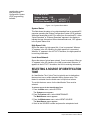
ALLOCATING AN IP ADDRESS TO THE PICO
In addition to programming the PiCo locally via the front-panel controls,
the system can also be programmed using the Eclipse Communication
System (ECS) software. To do so, however, the PiCo must be
connected to a computer, either directly or via a network. When the
PiCo is connected to a PC over a network an IP address must be
allocated to the PiCo (see the chapter on Operation for details of the
default IP address setup).
Note: For more information on the Eclipse Configuration System
(ECS), refer to its individual manual in the Eclipse set of
manuals.
To allocate an IP address to the PiCo
1. From the Main menu, select SYSTEM.
Clear-Com Communication Systems
Eclipse PiCo Matrix Instruction Manual
3-7
The System menu appears.
2. From the System menu, select IP ADDRESS.
The IP Address menu appears. If the matrix software has been
reloaded or reset the default IP address of 172.16.2.100 will be
displayed.
3. Scroll to the first digit of the IP Address.
4. Press the setup/enter knob.
5. Rotate the setup/enter knob clockwise or counterclockwise to scroll
through the available digits.
6. When the desired digit appears in the display, press the setup/enter
knob to select and save it.
7. Rotate the setup/enter knob clockwise or counterclockwise to scroll
to the next digit and repeat steps 4 through 6.
8. Repeat step 7 as many times as needed to enter the entire IP
address.
9. Repeat the same procedure for the Subnet Mask field.
10. Scroll to and select SAVE.
A confirmation screen appears asking for confirmation of the
selection. Select YES to accept the new IP address. Select NO or
EXIT to cancel any changes and revert to the current settings. The
Reset Options menu appears.
11. Select one of the following from the Reset Options menu.
• APPLY AND RESET resets the system to the currently selected
configuration, while restoring active calls and activating any
changes made from the PiCo’s front panel since the last reset.
• CLEAR XPOINTS resets the system to the currently selected
configuration, while clearing active calls and clearing any changes
made from the PiCo’s front panel since the last reset.
The PiCo now has the IP address selected.
12. To exit the menu. scroll to and select EXIT.
RESETTING TO THE DEFAULT IP ADDRESS
The Eclipse Pico can also be reset to the default IP addresses using
the internal reset buttons (see the chapter on Operations). This will
reset the LAN ethernet port to the factory default address of
172.16.2.100. This procedure is not normally required as the IP
address can be set from the front panel as described above.
3-8
Clear-Com Communication Systems
Eclipse PiCo Matrix Instruction Manual
ACCESSING SYSTEM INFORMATION
Information about the system number and firmware version can be
accessed directly from the PiCo’s front panel.
To access the system number or firmware version
1. From the Main menu, select SYSTEM.
The System menu appears.
2. From the System menu, select INFORMATION.
The Information menu appears.
3. From the Information menu, select SYSTEM INFORMATION.
The System Information menu appears, showing the system
number and firmware version. These fields are not editable.
SYSTEM INFORMATION
System Number: [ 1 ]
Firmware Version:
XXXX XXXX XXXX XXXX
EXIT
[Date
]
Figure 3-9: System Information Menu
System Number
If more than one PiCo system links via a network, this field shows the
system number of this particular PiCo.
Firmware Version
Shows the currently active firmware version for the PiCo.
ACCESSING SYSTEM STATUS
Information about the system’s status, high speed link connection, and
local area network connection can be accessed directly from the
PiCo’s front panel.
To access status information
Note: All system resets
from the PiCo’s front
panel are intrusive
resets. The system
takes about 25 seconds
to re-initialize during a
reset. It is possible to
clear selected
crosspoints without
Clear-Com Communication Systems
Eclipse PiCo Matrix Instruction Manual
1. From the Main menu, select SYSTEM.
The System menu appears.
2. From the System menu, select INFORMATION.
The Information menu appears.
3. From the Information menu, select SYSTEM STATUS.
The System Status menu appears.
3-9
resetting the system
with the Eclipse
Configuration System
(ECS) programming
software.
SYSTEM STATUS
EXIT
System Status: [ OK
]
High Speed Link: UP [ ] ACTIVITY [ ]
Local Area Network: UP [ ] ACTIVITY [ ]
Figure 3-10: System Status Menu
System Status
This field shows the status of any data download from a connected PC
computer operating the Eclipse Configuration System (ECS) software.
When data downloads to the PiCo matrix from a connected PC, either
“Serial Download” or “Ethernet Download” appears in the display to
indicate the type of download. When the download ends, “OK” appears
in the System Status field.
High Speed Link
Shows the status of a high-speed link, if one is connected. When an
“X” appears in the UP checkbox, the high-speed link is connected.
When an “X” appears in the ACTIVITY checkbox, the high-speed link
is receiving information.
Local Area Network
Shows the status of a local area network, if one is connected. When an
“X” appears in the UP checkbox, the LAN is connected. When an “X”
appears in the ACTIVITY checkbox, the LAN is receiving information.
SELECTING A SOURCE OF IDENTIFICATION
TONE
An “Identification Tone” (Ident Tone) is typically sent to destinations
that require a tone or audio statement during system setup. This
feature is activated from the Audio menu’s output level screen.
To use this feature a source for the Identification Tone must be
selected.
To select a source for the Identification Tone
1. From the Main menu, select SYSTEM.
The System menu appears.
2. From the System menu, select MAINTENANCE.
The Maintenance menu appears.
3. From the Maintenance menu, select IDENT SOURCE.
The Ident Source menu appears.
4. Scroll to the SOURCE number and press the setup/enter knob.
3-10
Clear-Com Communication Systems
Eclipse PiCo Matrix Instruction Manual
5. Rotate the setup/enter knob clockwise or counterclockwise to scroll
through the available digits.
6. When the desired digit appears in the display, press the setup/enter
knob to select and save it.
7. Scroll to and select SAVE to save and activate the source of
Identification Tone.
8. To exit the menu, scroll to and select EXIT.
Clear-Com Communication Systems
Eclipse PiCo Matrix Instruction Manual
3-11
RESETTING THE SYSTEM
Resetting the system restores the currently selected configuration
map, while restoring active calls and activating any changes made
from the PiCo’s front panel since the last reset.
Another type of reset restores the currently selected configuration
map, while clearing active calls and clearing any changes made from
the PiCo’s front panel since the last reset. This is called “clearing
crosspoints” (CLEAR XPOINTS).
To reset the system or clear crosspoints
1. From the Main menu, select SYSTEM.
2. From the System menu, select MAINTENANCE.
The Maintenance menu appears.
MAINTENANCE MENU
Ident Source
EXIT
Reset Options
Figure 3-11: Maintenance Menu
3. Scroll to and select RESET OPTIONS.
The Reset menu appears.
RESET MENU
EXIT
RESET
CLEAR XPOINTS
Figure 3-12: Reset Menu
4. Scroll to and select either RESET or CLEAR XPOINTS.
• RESET resets the system to the currently selected configuration,
while restoring active calls and activating any changes made from
the front panel since the last reset.
• CLEAR XPOINTS resets the system to the currently selected
configuration, while clearing active calls and clearing any changes
made from the front panel since the last reset.
5. To exit this menu, scroll to and select EXIT.
3-12
Clear-Com Communication Systems
Eclipse PiCo Matrix Instruction Manual
CHECKING THE STATUS OF GENERAL PURPOSE INPUTS (GPIS)
It is possible to connect an external logic device–such as an external
foot switch, a panel-mounted switch, or the logic output of some other
device–to the “GP IN” connector on the rear panel of the PiCo.
When the external logic device is activated, it sends a control signal
into the matrix to perform one of several preset functions, such as
turning an intercom panel’s microphone on or off, muting a
microphone’s output, or turning a panel’s speaker off. The function to
perform and the panel upon which it is performed is chosen from the
Eclipse Configuration System (ECS) programming software.
Once a GPI has been connected whether or not the GPI is “on” can be
checked directly from the front panel of the PiCo.
To check whether or not a general-purpose input is on
1. From the Main menu, select STATUS.
The Status menu appears.
2. From the Status menu, select GPI.
The GPI Status menu appears.
GPI STATUS
GPI 1 [ ]
GPI 5 [ ]
GPI 2 [ ] GPI 3 [ ]
GPI 6 [ ] GPI 7 [ ]
EXIT
GPI 4 [ ]
GPI 8 [ ]
Figure 3-13: GPI Status Menu
If a GPI is “on” an “X” will appear in the checkbox next to that GPI
number on the menu. An unchecked box indicates that the GPI is
“off.”
These fields cannot be edited. They are for information only.
3. To exit, scroll to and select EXIT.
CHECKING THE STATUS OF GENERAL PURPOSE OUTPUTS (GPOS)
A general purpose output or “relay” is a switch that is controlled
remotely. The relay is programmed in the Eclipse Configuration
System software to close a contact whenever an intercom panel’s key
is pressed. When the contact is closed, it completes an electronic
circuit’s signal path so that a remote device, such as a light, is
powered.
A GPO can be programmed to mute a speaker, to turn on an applause
light, to turn on a door lock, or to perform a variety of other functions.
For example, to get the attention of a panel operator working in a
Clear-Com Communication Systems
Eclipse PiCo Matrix Instruction Manual
3-13
high-noise environment such as a control booth, it can be programmed
as a relay to switch on a light at the panel each time an incoming call is
received to ensure that the call is not missed.
The general-purpose outputs are connected to the male 25-pin D-type
socket labeled “GP OUT” on the back of the PiCo.
After a GPO has been connected it is possible to check whether or not
a GPO is “on” directly from the front panel of the PiCo. A GPO can be
toggled “on” or “off” directly from the PiCo front panel as well.
The front panel display always shows the most current on/off status of
the GPO, whether it has been produced by using the front-panel
controls or by using the Eclipse Configuration System (ECS)
programming software.
To check whether or not a GPO is on and/or to toggle a GPO on/off
1. From the Main menu, select STATUS.
The Status menu appears.
2. From the Status menu, select GPO.
The GPO Status menu appears.
GPO STATUS
EXIT
GPO 1 [ ] GPO 2 [ ] GPO 3 [ ] GPO 4 [ ]
GPO 5 [ ] GPO 6 [ ] GPO 7 [ ] GPO 8 [ ]
Figure 3-14: GPO Status Menu
If a GPO is “on” an “X” appears in the checkbox next to that GPO
number on the menu. An unchecked box indicates that a GPO is
“off.”
3. To toggle a GPO on, scroll to and select its associated checkbox. To
toggle a GPO off, clear its associated checkbox.
A screen appears asking for confirmation of the selection. Select
YES to confirm. Select NO or EXIT to cancel the changes.
The GPO status menu always shows the current status of the GPO,
regardless of whether the status changes by using the front-panel
menu options or by using the Eclipse Configuration System
programming software.
4. To exit the menu, scroll to and select EXIT.
3-14
Clear-Com Communication Systems
Eclipse PiCo Matrix Instruction Manual
4
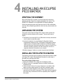
INSTALLING AN ECLIPSE
PICO MATRIX
VERIFYING THE SHIPMENT
When the Eclipse PiCo system is received inspect the boxes for
shipping damage. Report any shipping damage to the carrier. The
Eclipse PiCo distributor is not responsible for shipping damage.
Check the packing list and verify that every item on the list has been
received. Save all packing materials in the event any items need to be
returned.
UNPACKING THE SYSTEM
The system will include an Eclipse PiCo matrix which contains the
hardware, and the software for the system. The user will need to
supply:
• A standard 19 inch wide (48.26 cm) Electronics Industry Association
rack in which to install the matrix.
• A personal computer to run the Eclipse Configuration System
programming software (ECS). The Eclipse Configuration System
software runs on Windows 2000, Windows XP, Windows Server
2003 and Windows Vista (with restrictions). When running ECS on
Windows operating systems, the client and server can run on
separate machines connected over a network.
• Shielded category-5 cables to connect to panels and interfaces.
INSTALLING THE ECLIPSE PICO MATRIX
The following overview gives a summary of the steps required to install
an Eclipse PiCo matrix. More detailed information on each step is
provided in the sections that follow.
To install an Eclipse PiCo matrix:
1. Remove the Eclipse PiCo matrix from its shipping carton.
2. Place the matrix in a standard Electronic Industry Association
equipment rack.
3. Leave at least 2 inches (51 mm) of clearance on all sides of the
matrix to ensure proper airflow. Do not block ventilation vents.
4. Connect the power supplies to AC mains power using the IEC
connectors on the matrix’s rear panel. The matrix has two separate
AC power entry connectors for the two separate power supplies in
the system.
Clear-Com Communication Systems
Eclipse PiCo Matrix Instruction Manual
4-1
A fully equipped Eclipse PiCo matrix requires 100 to 240 VAC at 50 to
60 Hz with a maximum dissipation of 400 watts.
BATTERY BACKUP
The Eclipse PiCo matrix is fitted with a non-rechargeable battery to
maintain the system memory that stores the configuration maps and
other system data in the event of power failure or the unit being
switched off for a period of time.
The Eclipse PiCo battery is normally a 1/2AA 3V VARTA 6127-201-301
and would be fitted on shipment. This has a capacity of 970mAh and a
life of approximately 252 days.
Note: If the matrix is stored for more than three months, or if the
AC power to the matrix is regularly turned off (as in Outside
Broadcast vans), a qualified service person should be
contacted to disconnect the CPU backup battery before
storing the matrix. Only a qualified service person should
attempt to disconnect the battery. To contact a qualified
service person, please see the information in the Warranty
chapter.
WIRING THE MATRIX TO REMOTE DEVICES
The matrix holds the circuitry for connecting to, and communicating
with, the following:
• Thirty-two intercom panels or interfaces
• Eight general purpose outputs (GPOs or relays)
• Eight general purpose inputs (GPIs)
• Up to ten external GPI/RLY interfaces
• An additional Eclipse PiCo matrix to form a 64-port linked system
• A local area network (LAN) connection for Ethernet-based
communication with a network
• An external computer
The following sections describe the wiring for these connections.
Note: The instruction manual “Eclipse Matrix Installation Manual”
(part 810298Z) gives complete details about wiring remote
devices to the matrix. The manual also discusses RJ-45
cables and other types of cable required for system
installation.
4-2
Clear-Com Communication Systems
Eclipse PiCo Matrix Instruction Manual
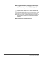
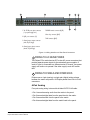
2
1
1 Two IEC AC power input connectors,
(1 per power-supply unit )
3
5
4
6
7
5 GPI/RLY interface connector (RJ-45)
6 Base loop connector (RJ-45)
2 RJ-45 port connectors (36)
7 LAN connector (RJ-45)
3 General purpose outputs connector
(male, 25-pin, D-type)
4 General purpose inputs connector
(female, 25-pin, D-type)
Figure 4-1: Wiring Interfaces to Rear-Panel Connectors
1
WIRING TO AC MAINS POWER
The Eclipse PiCo matrix has two IEC mains AC power connectors that
provide separate power inputs for the redundant power supplies. If
each AC input is connected to a different mains AC branch, one power
supply will continue to operate if the other supply’s main AC branch
fails.
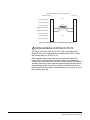
2
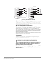
WIRING TO PANELS AND INTERFACES
Eclipse uses a 4-pair (analog) or single-pair (digital) wiring scheme
between the matrix and panels. All Eclipse panels have built-in RJ-45
connectors.
4-Pair Analog
Four-pair analog wiring is done with shielded CAT5 RJ-45 cable.
• Pair 1 transmits analog audio from the matrix to the panel.
• Pair 2 transmits digital data from the panel back to the matrix.
• Pair 3 transmits audio from the panel to the matrix.
• Pair 4 transmits digital data from the matrix back to the panel.
Clear-Com Communication Systems
Eclipse PiCo Matrix Instruction Manual
4-3
RJ-45 CONNECTOR
AT MATRIX PORT
RJ-45 CONNECTOR ON
PANEL OR INTERFACE
8 765 4 321
Views from
front of
connectors
8 765 4 321
Shielded category-5 cables wired pin-to-pin
Matrix Frame RJ-45 Pin Numbers
RS-422 Input +
(into Matrix)
1
RS-422 Input –
(into Matrix)
2
Audio Input +
(into Matrix)
3
Audio Output +
(from Matrix)
4
Audio Output –
(from Matrix)
5
Audio Input –
(into Matrix)
6
RS-422 Output +
(from Matrix)
7
RS-422 Output –
(from Matrix)
8
Panel RJ-45 Pin Numbers
Pair 2
Pair 1
Pair 3
Pair 4
Pair
Pair
Pair
Pair
1
2
3
4
1
RS-422 Output +
(from panel)
2
RS-422 Output –
(from panel)
3
Audio Output +
(from panel)
4
Audio Input +
(into panel)
5
Audio Input –
(into panel)
6
Audio Output –
(from panel)
7
RS-422 Input +
(into panel)
8
RS-422 Input –
(into panel)
Audio output from Matrix to panel
RS-422 data input from panel to Matrix
Audio input from panel to Matrix
RS-422 data output from Matrix to panel
Figure 4-2: Wiring Matrix to Analog Panel Using RJ-45
3
WIRING TO 4-WIRE EQUIPMENT
Eclipse Pico uses a 2-pair analog wiring scheme between the matrix
and 4-wire equipment. The wiring scheme shown in Figure 4-3 below
is for 4-wire equipment with an RJ-45 connector. For 4-wire equipment
with other types of connector the pin connections should be changed
in accordance with the installation specification for the 4-wire
equipment.
2-Pair Analog
Two-pair analog wiring to 4-wire equipment is done with shielded CAT5
RJ-45 cable if CAT5 cable is used or another suitable type of cable
depending on the 4-wire equipment.
• Pair 1 is not used.
• Pair 2 transmits digital data from the 4-wire equipment back to the
matrix.
• Pair 3 transmits audio from the 4-wire equipment to the matrix.
4-4
Clear-Com Communication Systems
Eclipse PiCo Matrix Instruction Manual
• Pair 4 is not used.
RJ-45 CONNECTOR
AT MATRIX PORT
8 7 65 4 32 1
RJ-45 PINOUT ON
4-WIRE EQUIPMENT
Views from
front of
connectors
8 765 4 321
Shielded category-5 cables wired pin-to-pin
Matrix Frame RJ-45 Pin Numbers
Not Used
1
Not Used
2
Audio Input +
(into Matrix)
3
Audio Output +
(from Matrix)
4
Audio Output –
(from Matrix)
5
Audio Input –
(into Matrix)
6
Not Used
7
Not Used
8
4-Wire Pin Numbers
Pair 2
Pair 1
Pair 3
Pair 4
Pair 1
Pair 2
Pair 3
Pair 4
1
Not Used
2
Not used
3
Audio Output +
4
Audio Input +
5
Audio Input –
6
Audio Output –
7
Not Used
8
Not Used
Audio output from Matrix to 4-Wire
Not used
Audio input from 4-Wire to Matrix
Not used
Figure 4-3: Wiring Matrix to 4-Wire Equipment Using RJ-45
Single-Pair Digital
Single-pair digital wiring is accomplished with double-shielded 24 AWG
conductor CAT-6E enhanced STP cable in the case of a DIG-2
interface or CAT5 cable for the AES-6-CX interface. Pair 1 transmits
and receives multiplexed digital and analog between the matrix frame
and the panel.
Note: Ensure that the “select” switch on the panel’s rear panel is
in the correct position for the intended use.
Clear-Com Communication Systems
Eclipse PiCo Matrix Instruction Manual
4-5
ATT-T568B (Modular Jumpers Wired One to One)
Panel End
Matrix Frame End
Pair 2
No Connection (NC)
1
No Connection (NC)
2
No Connection (NC)
3
Multiplexed Data/Audio
4
Multiplexed Data/Audio
5
No Connection (NC)
6
No Connection (NC)
7
No Connection (NC)
8
1
2
Pair 1
3
4
Pair 3
5
6
Pair 4
7
8
Figure 4-4: Wiring Matrix to Digital Panel Using RJ-45
4
WIRING GENERAL-PURPOSE OUTPUTS
The DB-25 connector labeled “GP OUT” allows connection to the
Eclipse PiCo matrix’s eight double-pole double-throw (DPDT) relays
with contact ratings of 30 VDC at 1A.
Each general-purpose output has a relay inside the Eclipse PiCo
matrix. When a general-purpose output is inactive, the associated
“common” pin on the GP OUT connector will be shorted to the relevant
“normally closed” pin. When a general-purpose output becomes active,
the short between the “common” pin and the “normally closed” pin is
broken and a new connection is made between the “common” pin and
the “normally open” pin.
4-6
Clear-Com Communication Systems
Eclipse PiCo Matrix Instruction Manual
DB-25 Male Connector
DESCRIPTION
PIN
1
2
3
4
5
6
7
8
9
10
11
12
13
14
15
16
17
18
19
20
21
22
23
24
25
RELAY
RELAY
RELAY
RELAY
1
1
1
2
Common
Normally Closed
Normally Open
Common
RELAY 2 Normally Closed
RELAY 2 Normally Open
RELAY 3 Common
RELAY 3 Normally Closed
RELAY 3 Normally Open
RELAY 4 Common
RELAY 4 Normally Closed
RELAY 4 Normally Open
GROUND
RELAY 5 Common
RELAY 5 Normally Closed
RELAY 5 Normally Open
RELAY 6 Common
RELAY 6 Normally Closed
RELAY 6 Normally Open
RELAY 7 Common
RELAY 7 Normally Closed
RELAY 7 Normally Open
RELAY 8 Common
RELAY 8 Normally Closed
RELAY 8 Normally Open
Common
RELAY 1
Normally Closed
Normally Open
Common
RELAY 2
Normally Closed
Normally Open
1
14
2
15
3
16
4
17
5
18
6
19
Common
RELAY 3
Normally Closed
Normally Open
Common
RELAY 4
Normally Closed
Normally Open
7
20
8
21
9
22
10
23
11
24
12
25
Digital Ground
Common
Normally Closed
RELAY 5
Normally Open
Common
Normally Closed
RELAY 6
Normally Open
Common
Normally Closed
RELAY 7
Normally Open
Common
Normally Closed
RELAY 8
Normally Open
13
30 VDC at 1 Ampere
Figure 4-5: Pin Configuration of the General-Purpose Outputs Connector
5
WIRING GENERAL-PURPOSE INPUTS
The DB-25 connector labeled “GP IN” connects the matrix to eight
local general-purpose inputs (GPIs).
When delivered from the factory, the general purpose inputs operate in
non-isolated mode. The non-isolated mode does not require that the
externally connected equipment powers the general-purpose input.
The current is supplied by a voltage output on the “GP IN” connector.
Clear-Com Communication Systems
Eclipse PiCo Matrix Instruction Manual
4-7
Non-Isolated Mode
Figure 4-6 shows the non-isolated connection.
+3V3
+3V3
+3V3
R
33K2
R
33K2
U
R29 1.5K
EXTERNAL INPUT 1
R30
1
8
2
7
3
6
4
5
INPUT 1
INPUT 2
1.5K
EXTERNAL INPUT 2
MOCD207-M
Figure 4-6: Non-Isolated Connection to Eclipse PiCo GPI Connector
To cause an input to detect an active signal current must be sent from
the relevant input pin.
The external device should draw no current to cause an inactive input
and at least 5 mA to cause an active input. The opto-isolator drive line
contains a 1.5 kOhm resistor to limit the current through the
opto-isolator. It is therefore possible to connect the input pins directly
to a ground pin to cause an active input.
The voltage level at the external input pin should not be allowed to go
below ground or above +6 V with respect to ground.
Opto-Isolated Mode
If required the Eclipse PiCo matrix can be operated in fully
opto-isolated mode. The unit must be taken out of service and
powered down before this change is made.
To operate the Eclipse PiCo matrix in opto-isolated mode
1. If the Eclipse PiCo unit is connected to AC power, disconnect it from
AC power.
2. Remove the top cover of the Eclipse PiCo matrix by unscrewing the
12 M3 x 6 flat screws and lifting the cover upwards.
3. On the internal circuit board, move the jumper located under the
heading “J6” from pins 2-3 (marked “INT”) to pins 1-2 (marked
“ISO”).
Warning: A circuit board’s components include CMOS chips that
are sensitive to static electricity. Before touching the matrix’s circuit
board touch a grounded metal object, such as any unpainted surface
on the matrix, to dissipate static electricity.When handling a circuit
board, be careful not to bend any of the board’s connector pins or
component leads.
Figure 4-7 shows the opto-isolated connection.
4-8
Clear-Com Communication Systems
Eclipse PiCo Matrix Instruction Manual
U
EXTVIN+
7-24V
8
+
C
10uF_25V
D
BYG22D
VIN
VOUT
LM78L05ACM
1
+3V3
+
+3V3
R
33K2
C
10uF_10V
R
33K2
U
R29 1.5K
EXTVIN-
1
8
EXTERNAL INPUT 1
2
7
3
6
R30
EXTERNAL INPUT 2
INPUT 1
INPUT 2
1.5K
4
5
MOCD207-M
Figure 4-7: Opto-Isolated Connection to Eclipse PiCo GPI Connector
In this mode, a DC voltage of between 7 and 24 volts is required at the
EXTVIN+ pin with relation to the EXTVIN– pin. To cause an input to
detect an active signal current must be sent from the relevant input pin.
The external device should draw no current to cause an inactive input
and at least 5 mA to cause an active input. The opto-isolator drive line
contains a 1.5 kOhm resistor to limit the current through the
opto-isolator. It is therefore possible to connect the input pins directly
to the EXTVIN– level to cause an active input.
The voltage level at the external input pin should not be allowed to go
below EXTVIN– or above +6 V with respect to EXTVIN–.
Clear-Com Communication Systems
Eclipse PiCo Matrix Instruction Manual
4-9
Pin Assignments for General-Purpose Inputs Connector
DB-25 Female Connector
PIN
1
2
3
4
5
6
7
8
9
10
11
12
13
14
15
16
17
18
19
20
21
22
23
24
25
DESCRIPTION
Logic Input 1
Logic Input 2
Logic Input 3
Logic Input 4
N/A
N/A
N/A
N/A
Ground
Ground
Ground
Ground
Ground
Logic Input 5
Logic Input 6
Logic Input 7
Logic Input 8
N/A
N/A
N/A
N/A
Voltage In+
Voltage In+
Voltage InVoltage In-
Logic Input 1
1
Logic Input 2
2
Logic Input 3
3
Logic Input 4
4
14
Logic Input 5
15
Logic Input 6
16
Logic Input 7
17
Logic Input 8
5
18
6
19
7
20
8
21
Ground
9
Ground
10
Ground
11
Ground
12
Ground
13
22
V IN+
23
V IN+
24
V IN–
25
V IN–
Figure 4-8: Pin Assignments for Eclipse PiCo General-Purpose Inputs Connector
6
WIRING TO A GPI/RLY INTERFACE
The RJ-45 connector labeled “GPI/RLY” connects up to 10 RLY-6 or
GPI-6 interfaces to the matrix.
The following sections give an overview of the wiring of these
interfaces. For more detailed discussion of wiring of interfaces in
general, see the Eclipse Matrix Installation Manual (part 810298Z).
RLY-6 Interface Wiring
The RLY-6 relay interface module connects up to six programmable
relays to the matrix so that each relay is directly controlled from the
matrix. Multiple RLY-6 interfaces can be daisy chained to provide
4-10
Clear-Com Communication Systems
Eclipse PiCo Matrix Instruction Manual
connection of up to 60 relays to the matrix. IMF-3 Interface Module
Frame Wiring
IMF-3 Interface Module Frame Wiring
To Matrix
To connect the RLY-6 interface to the matrix, plug one end of an RJ-45
cable (eight wires with no reversal) into the GPI/RLY INTERFACE
connector on the back of the matrix. Plug the other end into the top
RJ-45 (CH. A MATRIX) connector for the RLY-6.
To connect an additional RLY-6 interface, plug one end of a short
RJ-45 cable into the lower RJ-45 (CH. B MATRIX) for the first RLY-6.
Then, plug the other end into the top RJ-45 (CH. A MATRIX) connector
for the additional RLY-6.
Additional RLY-6 interfaces are added in the same way, using
"daisy-chain" wiring. If there are multiple RLY-6 interfaces, the inputs
in the first interface are numbered 1 to 6 for RLY 1; in the second
interface 1 to 6 for RLY 2, etc. RLY interface 0 is the internal Matrix
RLY interface.
For Eclipse systems if both GPI-6 and RLY-6 interfaces are used the
GPI-6 interfaces are required to be placed first in the daisy chain (see
Figure 4-9 below).
The maximum combined length of all the RJ-45 cables should not
exceed 20 ft. (6 m).
Clear-Com Communication Systems
Eclipse PiCo Matrix Instruction Manual
4-11
Ports
Rear View of IMF-3 Frame
GPI/RLY
Interface
Connector
RJ-45
RJ-45
RJ-45
RJ-45
RJ-45
DB-9
DB-9
DB-9
DB-9
DB-9
RJ-45
RJ-45
RJ-45
RJ-45
RJ-45
DB-9
DB-9
DB-9
DB-9
DB-9
Other
Interfaces
RLY-6
#2
RLY-6
#1
GPI-6
#2
GPI-6
#1
Figure 4-9: Rear View of IMF-3 Frame
To External Device
To connect external devices to the RLY-6 interface, use the two DB-9M
connectors on the rear cable assembly panel for the interface. Figure
4-10 shows the pin assignment of these connectors as viewed from
the matrix side of the connector.
If a DB-9F is plugged into the connector labeled CH. A I/O, relays 1 to
3 are available on that connector. The connector labeled CH. B I/O has
the contacts for relays 4 to 6. In Figure 4-10, the labels on the pins
apply to either connector. Example: #1/4 COM refers to the wiper of
relay 1 if it is connected to CH. A and the wiper of relay 4 if it is
connected to CH. B.
4-12
Clear-Com Communication Systems
Eclipse PiCo Matrix Instruction Manual
1
6
#1/4 Normally Closed
#1/4 COM
2
#1/4 Normally Open
#2/5 Normally Closed
7
3
8
#2/5 COM
#2/5 Normally Open
4
9
#3/6 Normally Closed
#3/6 COM
5
#3/6 Normally Open
Figure 4-10: RLY-6 Interface DB-9M Connector Pinout
IMF-102 Interface Module Frame Wiring
The wiring of a RLY-6 interface that is placed in an IMF-102 interface
frame is the same as the wiring for a RLY-6 interface placed in an
IMF-3 interface frame. The only difference is that an IMF-102 interface
frame houses only two interfaces, and they are mounted horizontally
rather than vertically in the frame.
Refer to the respective manuals for these interfaces and frames in the
Eclipse manual set for more information.
Configuration
To associate a relay to a label, use the Eclipse Configuration System,
(ECS) as described in the ECS manual.
GPI-6 Interface Wiring
The GPI-6 input interface module connects up to six programmable
inputs to the matrix so that each input can control a predefined matrix
function. Multiple GPI-6 interfaces can be daisy-chained to provide
connection of up to 60 inputs to the matrix. RLY-6 and GPI-6 interfaces
can be mixed together up to the total limit of 60 items. Five RLY-6 and
five GPI-6 interfaces would provide 30 relays and 30 inputs for a total
of 60 inputs and outputs.
Note: If both GPI-6 and RLY-6 interfaces are used the GPI-6
interfaces are required to be placed first in the daisy chain.
Clear-Com Communication Systems
Eclipse PiCo Matrix Instruction Manual
4-13
IMF-3 Interface Module Frame Wiring
To Matrix
To connect the GPI-6 to the matrix, plug one end of an RJ-45 cable
(eight wires with no reversal) into the GPI/RLY INTERFACE connector
on the back of the matrix. Plug the other end into the top RJ-45 (CH. A
MATRIX) connector for the GPI-6.
To connect an additional GPI-6 interface, plug one end of a short
RJ-45 cable into the lower RJ-45 (CH. B MATRIX) for the first GPI-6.
Then, plug the other end into the top RJ-45 (CH. A MATRIX) connector
for the additional GPI-6.
Additional GPI-6 interfaces are added in the same way, using
"daisy-chain" wiring. If there are multiple GPI-6 interfaces, the inputs
in the first interface are numbered 1 to 6 for GPI 1; in the second
interface 1 to 6 for GPI 2, etc. GPI interface 0 is the internal Matrix GPI
interface.
For Eclipse systems if both GPI-6 and RLY-6 interfaces are used the
GPI-6 interfaces are required to be placed first in the daisy chain (see
Figure 4-9).
The maximum combined length of all the RJ-45 cables should not
exceed 20 ft. (6 m).
To External Device
To connect external devices to the GPI-6 interface, use the two DB-9M
connectors on the rear cable assembly panel for the interface. Figure
10 shows the pin assignment of these connectors as viewed from the
matrix side of the connector.
If a DB-9F is plugged into the connector labeled CH. A I/O, inputs 1
through 3 are available on that connector. The connector labeled CH.
B I/O has inputs 4 through 6. In Figure 4-11, the labels on the pins
apply to either connector.
1
6
#1/4 Input A
#1/4 Input B
2
#2/5 Input A
#2/5 Input B
7
3
8
#3/6 Input A
#3/6 Input B
4
Ground
5
Ground
9
Power Source
Figure 4-11: GPI-6 Interface DB-9M Connector Pinout
4-14
Clear-Com Communication Systems
Eclipse PiCo Matrix Instruction Manual
GPI-6 I/O DB-9M
GPI-6 I/O DB-9M
1
1
6
6
2
2
7
7
3
3
8
8
4
X
9
4
5
X
X
9
5
X
Figure 4-12: GPI-6 Application Examples
Figure 4-11 and Figure 4-12 show how to connect switches or contacts
using the power source provided by the GPI-6 module or powering
switches from external sources. Each input can be wired to be isolated
from each other as a further variation.
IMF-102 Interface Module Frame Wiring
The wiring of a GPI-6 interface that is placed in an IMF-102 interface
frame is the same as the wiring for a GPI-6 interface placed in an
IMF-3 interface frame. The only difference is that an IMF-102 interface
frame houses only two interfaces, and they are mounted horizontally
rather than vertically in the frame.
Refer to the respective manuals for these interfaces and frames in the
Eclipse manual set for more information.
Configuration
To define an input function, use the Eclipse Configuration System
program, as described in its manual.
7
WIRING TO A SECOND ECLIPSE MATRIX
The RJ-45 connector labeled “Base Loop” connects the Eclipse PiCo
matrix to a second Eclipse PiCo matrix’s “Base Loop” connector to
form one non-blocking 64 port Eclipse system.
To make this connection, use a specially constructed screened CAT-5
cable of maximum length 1 meter (3.28 feet). The cable is wired as
shown in Table 4-1.
Clear-Com Communication Systems
Eclipse PiCo Matrix Instruction Manual
4-15
.
CABLE END 1
WIRE COLOR
CABLE END 2
Pin 1
white/orange
Pin 3
Pin 2
orange
Pin 6
Pin 3
white/green
Pin 1
Pin 4
blue
Pin 4
Pin 5
white/blue
Pin 5
Pin 6
green
Pin 2
Pin 7
white/brown
Pin 7
Pin 8
brown
Pin 8
Table 4-1: Pin Configuration of Base Loop Connector
Note: To transfer data between two linked PiCo matrices using
the high-speed link also requires that the Ethernet ports are
connected with either a cross-over shielded CAT-5 cable or
a with a hub or switch using conventional shielded CAT-5
cable.
8
WIRING TO A LOCAL AREA NETWORK
The LAN connector has standard Ethernet pin assignments.
LAN1 and LAN2
Ethernet RJ-45 Connectors
8 765 4 321
PIN
1
2
3
4
5
6
7
8
FUNCTION
Transmit data +
Transmit data –
Receive data +
Unused
Unused
Receive data –
Unused
Unused
Figure 4-13: Pin Assignments for LAN Connector
4-16
Clear-Com Communication Systems
Eclipse PiCo Matrix Instruction Manual
WIRING TO A COMPUTER
The 3.5 mm connector on the PiCo unit’s front panel connects the
Eclipse PiCo matrix to an external computer. This connector is labeled
“RS-232.”
To connect a computer to the matrix, run cable from the PiCo’s
“RS-232” connector to the PC’s serial port. The maximum
recommended length of the cable is approximately 10 feet (3 meters).
pc connection (9-pin f)
pico connection (3.5 mm jack)
1
N/C
2
tip
3
ring
4
N/C
5
screen
6
N/C
7
N/C
8
N/C
9
N/C
Figure 4-14: Pinout for cable to connect PiCo matrix to external computer
Clear-Com Communication Systems
Eclipse PiCo Matrix Instruction Manual
4-17
4-18
Clear-Com Communication Systems
Eclipse PiCo Matrix Instruction Manual
5
MAINTAINING AN
ECLIPSE PICO
MATRIX
RECOMMENDED SPARE PARTS
To facilitate quick repair of the system with minimum downtime,
Clear-Com recommends keeping the following spare system
components in good working condition at all times:
• One of each type of intercom panel in the system
• One of each type of interface in the system
Due to the complexity of the system, field service generally should be
limited to isolating the specific component of the system with the
problem.
DUAL, INDEPENDENT POWER SUPPLIES
The Eclipse PiCo matrix includes two internal power supply units. One
power supply unit can power an entire matrix; the second unit provides
a backup in case of an equipment failure.
In addition, the two supplies have separate IEC connectors to AC
mains power, and are designed for completely automatic and
transparent changeover between supplies in the event of a power
failure on one of the AC branches.
Clear-Com Communication Systems
Eclipse PiCo Matrix Instruction Manual
5-1
5-2
Clear-Com Communication Systems
Eclipse PiCo Matrix Instruction Manual
6
SPECIFICATIONS
ECLIPSE PICO TECHNICAL SPECIFICATION
0 dBu is referenced to 0.775 volts RMS
General
Height
44 mm or 1.75 inches (1 RU)
Width
482 mm (19 inches)
Depth
300 mm (12 inches)
Weight
5 kg max.
Power Consumption
60 W Max. per inlet
Number of Panel Compatible Ports 32
Number of Analog Audio Ports
4
Number of Expansion Modules
1
Number of Power Supply Units
2
Maximum Number of Ports Per SystemCan intelligently link 2 Eclipse PiCo
matrices
Matrix Performance
Sample Rate
48 kHz
Resolution
24 bit
Frequency Response @ 48 kHz sampling30 Hz – 22 kHz ± 3 dBu
Crosstalk (adjacent channel)
<–70 dBu
Nominal Level
0 dBu
Matrix headroom
18 dBu
Distortion
<0.05 %, @ 0 dBu, 300 Hz to 10 kHz;
<0.1 %, @ 0 dBu, 100 Hz to 20 kHz
Off Noise
<–98 dBu relative to +18 dBu,
20 Hz - 22kHz
On Noise
<–83 dB relative to +18 dBu, 20 Hz - 22
kHz
Key Response, Intra-System
<40 ms for audio route
Linked Systems
<60 ms for audio between matrices
Temperature
0 to +40 ° C, ambient;
-55 ° to +70 ° C, storage
Humidity, Maximum
90% non-condensing
Matrix Interfaces
Clear-Com Communication Systems
Eclipse PiCo Matrix Instruction Manual
GPI inputs
8 total; opto-isolated
GPI outputs (relays)
8 total; isolated relay contacts
GPI connector
25-pin D-type socket on rear panel
GPO connector
25-pin D-type plug on rear panel
6-1
External GPI-6/RLY-6
RJ-45 on rear panel
Network
10/100 Base-T Ethernet
maximum distance: 100 meters
connector RJ-45
Serial PC
RS-232
Baud rate: 57600
Maximum distance: 10 meters
Number of ports: 1
Connector: 3.5 mm socket on front
System Programming
Crosspoint Level Control
Input Level Control
Output Level Control
VOX Input Detection Threshold
0.355 dB steps
0.355 dB steps
0.355 dB steps
0 dB to – 40 dB adjustable
Minimum PC Requirements
Processor
Memory
Hard Disk
Input Devices
Display Resolution
User Entry
Ports
Network
Operating Systems
Pentium III 600 MHz
512 MB RAM
500 MB
CD-ROM Drive
SVGA
Keyboard, Mouse
2 serial ports and/or network IEEE 802.3
Ethernet card
IEEE 802.3 Ethernet Card
Windows 2000 / Windows XP
/ Windows 2003 Server / Windows Vista
(with restrictions)
Recommended PC Requirements
Processor
Memory
Free Space
Display Resolution
Operating Systems
6-2
Pentium III 800 MHz or greater
1GB or greater
500 MB
1600 X 1200
Windows 2000 / Windows XP
/ Windows 2003 Server / Windows Vista
(with restrictions)
Clear-Com Communication Systems
Eclipse PiCo Matrix Instruction Manual
Power Supply Unit
Quantity
Mounting
AC Power Input
Input Voltage
Power Consumption
Alarm Indicators
2 per matrix
Internal
IEC (1 per PSU)
AC 100 V to 240 V, 50/60 Hz
60 W maximum
LEDs viewable from front of rack
Supported Panels and Interfaces: ICS-1008, ICS-1016, ICS-52,
ICS-92, ICS-62, ICS-102, IMF-102, ICS-2003, i-Station family,
ICS-21/22/24, XPL-22, XPL-12, IMF-3, TEL-14, CCI-22, FOR-22,
RLY-6, GPI-6, DIG-2, AES-6, 4000 Series II Panels 4215EBL,
4226EBL, 4212EBL, 4222EBL, 4294EBL, V-Series Panels.
Notice About Specifications
While Clear-Com makes every attempt to maintain the accuracy of the
information contained in its product manuals, that information is
subject to change without notice. Performance specifications included
in this manual are design-center specifications and are included for
customer guidance and to facilitate system installation. Actual
operating performance may vary.
Clear-Com Communication Systems
Eclipse PiCo Matrix Instruction Manual
6-3
6-4
Clear-Com Communication Systems
Eclipse PiCo Matrix Instruction Manual
7
APPENDIX: PICO
MENU MAP
System Status
System Status [OK
High-Speed Link
Local Area Network
EXIT
UP [
UP [
]
]
]
Activity [
Activity[
Main Menu
STATUS
This map shows an overview
of the PiCo’s front panel
menus.
]
]
EXIT
AUDIO ROUTING CONFIGS SYSTEM
Status Menu
EXIT
PORTS
STATUS
GPI
GPO
System Ports
EXIT
PORTS
GPI Status
EXIT
GPI 1 [ ] GPI 2 [ ] GPI 3 [ ] GPI 4 [ ]
GPI 5 [ ] GPI 6 [ ] GPI 7 [ ] GPI 8 [ ]
GPI
GPO Status
EXIT
GPO 1 [ ] GPO 2 [ ] GPO 3 [ ] GPO 4 [ ]
GPO 5 [ ] GPO 6 [ ] GPO 7 [ ] GPO 8 [ ]
GPO
Audio Menu
AUDIO
EXIT
INPUTS
OUTPUTS
Clear Ident Tone Routes
Input Level
Output Level
Port <00> [
Level <- 0> dB
OUTPUTS
Routes
<SAVE>
Source
<00> [Src Label]
Destination <00> [Dst Label}
Enable [ x ]
Inhibit [
ROUTING
Configuration
MapName 1 [ ]
MapName 3 [ ]
CONFIGS
IP ADDRESS
]
EXIT
]
EXIT
]
MapName 2 [
MapName 4 [
EXIT
]
]
System Menu
SYSTEM
EXIT
Port <00> [
Level <- 0> dB
INPUTS
EXIT
INFORMATION MAINTENANCE
IP Address
SAVE
EXIT
IP <000.000.000.000>
Mask <000.000.000.000>
IP ADDRESS
Information Menu
SYSTEM INFO
EXIT
System Information
System Status
System Informaton
Systen Number [
Firmware Version:
SYSTEM INFO
FT215F 0758
SYSTEM STATUS
System Status
System Status [OK
High-Speed Link
Local Area Network
Maintenance Menu
IDENT SOURCE
MAINTENANCE
Note: This menu map does not
include screens for confirmation and reboot,
which occur automatically after some
menus.
IDENT
SOURCE
REBOOT
OPTIONS
EXIT
]
[Date
]
EXIT
UP [
UP [
]
]
]
Activity [
Activity[
]
]
EXIT
REBOOT OPTIONS
System Ident Tone Source
Source <00>
Rebott Options
RESET
SAVE
EXIT
[Source Label ]
EXIT
DEFAULT
CLEAR XPOINTS
Figure 7-1: Eclipse PiCo Menu Map
Vitec Group Communications
Eclipse PiCo Matrix Instruction Manual
7-1
7-2
Vitec Group Communications
Eclipse PiCo Matrix Instruction Manual
8
GLOSSARY
Analog Port Any of the Eclipse matrix’s analog input/output RJ-45
connectors that are used to connect cable from the matrix to panels
and interfaces. Each “port” connects to a separate audio channel in the
matrix intercom system.
Bus A bus is the channel or path between the components in the
matrix along which electrical signals flow to carry information from one
component to the next. In the Eclipse matrix the bus is located in the
etched surface of the midplane.
Call Signal A call signal is an electronic signal sent from one panel or
interface to another. A call signal can be audible and/or visual.
Typically a call signal is sent to get the attention of a panel operator
who may have turned down their intercom speaker’s volume or
removed their headset. It can also be sent to activate an electronic
relay.
Category-5 cable EIA/TIA 568 category specification relating to
network cabling. Shielded category-5 cabling is required for Eclipse
matrix wiring.
CellCom Digital wireless communications product. Sold under the
CellCom name in USA and as FreeSpeak in Europe and Asia.
Central Matrix The term “central matrix” is used to differentiate the
central hardware and software of the intercom system from the
connected audio devices. The central matrix consists of:
1. The metal housing for the circuit cards and power supplies.
2. The circuit cards.
3. The power supplies.
4. The rear panel connectors which connect the matrix’s hardware to
panels and interfaces.
Destination A device such as an intercom panel, beltpack, or interface
to which audio signals are sent. The device from which audio signals
are sent is called a “source”.
Duplex All real-time communication between individuals talking face to
face is full duplex, meaning that they can both talk and listen
simultaneously. The Eclipse Omega matrix provides full-duplex audio.
ECS Eclipse Configuration System. Software program that guides the
operation of the central matrix circuit cards and connected panels.
EMS Element Management System. Software program that is used to
manage the Concert server system resources.
Ethernet International standard which describes how information is
transmitted across a network. Provides for the efficient organization of
network components.
Clear-Com Communication Systems
Eclipse Glossary
8-1
Fiber-optic Cable A fiber-optic cable consists of a glass core covered
with a reflective material called “cladding” and several layers of buffer
coating to protect the cable from the environment. A laser sends light
pulses through the glass core to the other end of the cable.
FreeSpeak Digital wireless communications product. Sold under the
FreeSpeak name in Europe and Asia and CellCom in USA.
Full Duplex Refers to transmission of signals in two directions
simultaneously.
IFB “Interruptible Foldback”. The term “foldback” refers to sending
“program” audio, or some other audio mix, back to announcers while
they are on the air. Doing so allows announcers to monitor
themselves, other announcers, videotapes of commercials, or some
mix of sources, while they on the air. This is typically found in television
news and live broadcast events.
Announcers typically wear a small ear piece so they can hear the
selected foldback audio mix. When a director wants to give directions
to an announcer on air, or to announce changes in the program, the
director must “interrupt” the foldback. To do this, the director uses a
channel specifically set up to interrupt the foldback audio.
Interface Module A piece of electronic hardware designed to convert
the 4-wire signals of a central matrix port to some other form of
communication, such as 2-wire party line, telephone, etc. The interface
module is connected to a central matrix port. The external non-4-wire
device is then connected to the interface module.
ISO The ISO function, short for “panel ISOlation”, allows a panel
operator to call a destination and interrupt all of that destination’s other
audio paths and establish a private conversation. When the call is
completed the destination’s audio pathways are restored to their
original state before the interruption.
IV-R Instant Voice Router. Software that routes digital audio data
between Concert users and between Concert users and Eclipse
systems.
Label A label is an alphanumeric name of up to five characters that
identifies a source, destination, or control function accessed by an
intercom panel. Labels appear in the displays of the intercom panel.
Labels can identify panels, ports interfaced to other external
equipment, fixed groups, party lines, and special control functions.
Mode A term used to describe a light path through a fiber as in
multimode or single mode.
Multimode Fiber-optic Cable The glass core of a multimode fiber is
larger than the core of a single mode fiber, which causes the
transmitted light beam to disperse as it travels through the core. Single
mode fiber, with its smaller core, concentrates the light beam so that it
carries signals further. Multimode fiber was the first type of fiber offered
8-2
Clear-Com Communication Systems
Eclipse Glossary
by manufacturers. Single-mode fiber evolved as production methods
improved.
Multiplexing The process by which two or more signals are
transmitted over a single communications channel. Examples include
time division and wavelength division multiplexing.
Nanometer (nm) Common unit of measure for wavelength. One
billionth of a meter.
Non-volatile Memory Data stored in the CPU’s firmware (ROM) that
is not lost when the power is turned off.
Optical Signal A laser at one end of a fiber-optic cable pulses on or off
to send a light signal through the glass core of the cable to the other
end of the cable. Because the light signals are binary (on or off), the
signal is digital.
Panel Also referred to as “station” in some cases (usually older
manuals). Any intelligent intercom device connected to the rear-panel
analog ports of the central matrix. This term does not refer to devices
connected through interface modules.
Port Any of the input/output connections (RJ-45 connectors) on the
back panel of the central matrix. These connectors and the attached
cables connect the central matrix to remote intercom devices. The
term “port” emphasizes that the connection is a “portal” between the
central matrix and the remote intercom devices.
Program Any separate audio source that is fed into the intercom
channels. In television applications, for example, “program” audio is
the audio that is broadcast on air.
Rack Unit or RU Standardized unit of mounting space on a rack panel.
Each rack unit is 1.75 inches (44.45 mm) of vertical mounting space.
Therefore 1 RU is 1.75 inches (44.45 mm) of vertical mounting space,
2 RU is 3.5 inches (88.9 mm), 3 RU is 5.25 inches (133.35 mm), and
so on.
Remote Panel Any intelligent intercom device connected to the
back-panel ports of the central matrix. This term does not refer to
devices connected through interfaces.
Sidetone The sound of the panel operator’s own voice heard in their
own earphone as they speak.
Single-mode Fiber-optic Cable The glass core of a single-mode fiber
is smaller in diameter than the core of a multimode fiber, so that the
light signal transmitted over the core is more concentrated than with
multimode fiber, which allows the signal to travel further. Single-mode
fiber evolved from multimode fiber as production methods improved.
Source In this manual, the term “source” refers to a device—such as
an intercom panel, interface, or beltpack —that sends audio into the
matrix. The device to which audio is sent is called a “destination”.
Clear-Com Communication Systems
Eclipse Glossary
8-3
VOX In the Eclipse system, when audio at a panel exceeds a
threshold, a light switches on at the panel’s port card to visually cue the
operator. The threshold level is set in the Eclipse Configuration
Software.
V-Series Communications panels used with Eclipse systems providing
advanced facilities. Available in rack mount and desktop formats.
Wavelength-division Multiplexing (WDM) A method of multiplexing
optical signals developed for use on fiber-optic cable. Each signal is
assigned a particular wavelength on the light spectrum and therefore
many signals can be transmitted simultaneously without interfering
with each other.
8-4
Clear-Com Communication Systems
Eclipse Glossary
ECLIPSE MANUALS
The following manuals are available covering Eclipse products and
accessories.
SOFTWARE MANUALS
Eclipse Configuration System (ECS) Instruction Manual - 810299Z
Eclipse Logic Maestro Instruction Manual - 810414Z
Eclipse Production Maestro Quick Start Guide - 810409Z
Eclipse Production Maestro Installation and User Guide - 810410Z
Eclipse DECTSync Manual - 810412Z
Eclipse Host Computer Interface (HCI) Manual - 810413Z
HARDWARE MANUALS
Eclipse Omega Matrix Instruction Manual - 810290Z
Eclipse Median Matrix Instruction Manual - 810347Z
Eclipse PiCo Matrix Instruction Manual - 810348Z
Eclipse-32 Matrix Instruction Manual - 810315Z
Eclipse Matrix Installation Manual - 810298Z
Eclipse Upgrade Reference Manual - 810377Z
Eclipse V-Series Panels User Manual - 810365Z
Eclipse FOR-22 4-Wire Interface Instruction Manual - 810306Z
Eclipse CCI-22 Party Line Interface Instruction Manual - 810307Z
Eclipse TEL-14 Telephone Interface Instruction Manual - 810308Z
Eclipse GPI-6 General Purpose Inputs Instruction Manual - 810309Z
Eclipse RLY-6 General Purpose Outputs Instruction Manual - 810310Z
DIG-2 Digital Interface Instruction Manual - 810311Z
IMF-3, IMF-102, DIF-102 Interface Module Frame Instruction Manual 810313Z
Eclipse AES-6 Digital Interface Instruction Manual - 810383Z
Eclipse BAL-8 Isolation Interface Instruction Manual - 810403Z
Eclipse V-Series AES-3 Option Card Installation Instructions 810388Z
Eclipse V-Series XLR-7M Upgrade Instructions - 810405Z
Eclipse V-Series T-Adapter Installation Instructions - 810406Z
Eclipse FIM-202D Fiber Interface Instruction Manual - 810385Z
Clear-Com Communication Systems
Eclipse Manuals
8-5
Eclipse FIM-102 Fiber Interface Instruction Manual - 810319Z
Eclipse FIM-108 Fiber Interface Instruction Manual - 810291Z
Eclipse 4000 Series II Panels Installation Guide - STA0530Z
Eclipse 4000 Series II Panels User Guide - STA0531Z
Eclipse ICS 1008E/1016E Panels Instruction Manual - 810404Z
Eclipse ICS 102/62 Panels Instruction Manual - 810302Z
Eclipse ICS 2003 Panel Instruction Manual 810303Z
Eclipse ICS 92/52 Panels Instruction Manual - 810301Z
Eclipse i-Station Instruction Manual - 810305Z
Eclipse ICS-21 Speaker Panel Instruction Manual - 810263Z
Eclipse ICS-22 Speaker Panel Instruction Manual - 810264Z
Eclipse ICS-24 Headset Panel Instruction Manual - 810265Z
Eclipse Digital Wireless Beltpack Instruction Manual - 810376Z
8-6
Clear-Com Communication Systems
Eclipse Manuals
LIMITED WARRANTY
This document details the Clear-Com Standard Limited Warranty for all new products for sale within all
regions with the exception of Military, Aerospace, and Government (MAG).
EXCEPT AS SET FORTH HEREIN ("LIMITED WARRANTY"), CLEAR-COM MAKES NO OTHER
WARRANTIES, EXPRESS, IMPLIED OR STATUTORY, INCLUDING WITHOUT LIMITATION ANY
WARRANTIES OF MERCHANTABILITY, NONINFRINGEMENT OF THIRD PARTY RIGHTS, OR
FITNESS FOR A PARTICULAR PURPOSE, ALL OF WHICH ARE EXPRESSLY DISCLAIMED.
1. Standard Limited Warranty. Clear-Com Communication Systems ("Clear-Com") warrants its
products, including supplied accessories, against defects in material or workmanship for the time
periods as set forth below provided it was purchased from an authorized Clear-Com dealer or
distributor.
a) Pursuant to this Limited Warranty, Clear-Com will, at its option:
i)
repair the product using new or refurbished parts, or;
ii) replace the product with a new or refurbished product.
b) Remedies: In the event of a defect, the rights detailed in 1 (a) are your exclusive remedies. For
purposes of this Limited Warranty, "refurbished" means a product or part that has been returned
to its original specifications.
c) Standard Warranty Period (by Product):
i)
All Clear-Com brand systems and products, including belt packs, have a Limited Warranty
of two years, with the exception of;
(1) Cables, accessories, components & consumable items have a Limited Warranty of 90
days.
(2) Any Clear-Com product that has been classified as obsolete at the time of sale has a
Limited Warranty of 90 days from sales and will be replaced with the same product or a
sales credit will be issued, at the sole discretion of Clear-Com.
(3) Headsets, handsets, microphones, and associated spare parts, as well as UHF wireless
IFB products, have a Limited Warranty of one year.
(4) UHF WBS Analog wireless intercom systems have a Limited Warranty of three years.
Clear-Com Communication Systems
Standard Limited Warranty
i
(5) All software products, including Concert (Client and Server), ECS, Production Maestro
and Logic Maestro are warranted for one year and shall substantially conform to
published specifications. The media on which the Software is furnished is warranted to
be free of defects in material and workmanship (under normal use) for a period of one
year.
(6) Any Clear-Com products that are listed within the last time buy period have the same
Limited Warranty for their type 1.i 1 - 1.i.5 as above.
d) Any Clear-Com product that is repaired or supplied as a replacement under the terms of this
Limited Warranty shall inherit the remaining warranty period from the original product.
e) Standard Warranty Period Start Date
i)
Dealer / Distributor Sales: In view of Dealer or Distributor stocking practices, the Standard
Warranty Period for products sold through Dealers or Distributors will commence from the
Clear-Com invoice date and will include an automatic extension of three months. Any valid
warranty claim within the Standard Warranty Period as determined by the Clear-Com
invoice date will be covered without further supporting evidence. All warranty claims after
this date must be supported by the Customer's proof of purchase that demonstrates the
product is still within the Standard Warranty Period (as detailed in Section 1.c.i above, plus
the automatic three month extension) from their purchase date.
ii) Direct Sales: The Standard Warranty Period will commence from the date the product was
shipped from Clear-Com to the Customer. The Standard Warranty Period start date for
contracts that include commissioning will be the date of the Site Acceptance Test (SAT) or
one month from conclusion of the commissioning project, whichever is earlier.
f) Invalidation of Warranty
i)
This Limited Warranty shall be invalidated if the product's outer case has been opened and
internal modifications have been made or damage has occurred, or upon the occurrence of
other damage or failure not attributable to normal wear and tear. Authorized modifications
with Clear-Com's express written permission will not invalidate the warranty.
g) Software Updates
i)
ii
Software Updates are released periodically to correct discovered program bugs. During the
Warranty Period, software updates are available to Customers free of charge.
Clear-Com Communication Systems
Standard Limited Warranty
h) Software Upgrades
i)
Software Upgrades include new Features and/or Functional Enhancements and are not
included as part of the Standard Warranty but may be purchased at the published rates.
ii) Note: In the absence of a Software Update containing a program correction and no
available workaround to mitigate the problem, at the discretion of Service, Sales,
Engineering, or Product Management, the Customer may be provided a Software Upgrade
under warranty.
2. Exclusions. Services do not cover damage or failure caused by any occurrence beyond Clear-Com's
reasonable control, including without limitation acts of God, fire, flooding, earthquake, lightning, failure
of electric power or air conditioning, neglect, misuse, improper operation, war, government
regulations, supply shortages, riots, sabotage, terrorism, unauthorized modifications or repair, strikes,
labor disputes or any product failure that Clear-Com determines is not a result of failure in the
Services provided by Clear-Com. Further Services excluded from this Agreement include: services
required due to errors or omissions in Customer purchase orders; installation or maintenance of
wiring, circuits, electrical conduits or devices external to the products; replacement or reconditioning
of products which, in Clear-Com's opinion cannot be reliably maintained or properly serviced due to
excessive wear or deterioration; Customer's failure to maintain the installation site in accordance with
the environmental specifications of the products; or service on products removed from the location
originally specified by Customer and/or reinstalled without the prior written approval of Clear-Com.
Customer will pay Clear-Com's then current published charges to restore such Covered Products to a
condition eligible for further service under this Agreement. Clear-Com shall be excused from and shall
not be liable for any failure or delay in performance under this Agreement due to the foregoing or any
causes beyond its reasonable control.
3. Limitation of Liability. IN NO EVENT WILL CLEAR-COM BE LIABLE UNDER THIS AGREEMENT
FOR ANY INDIRECT, SPECIAL, INCIDENTAL OR CONSEQUENTIAL DAMAGES (INCLUDING
WITHOUT LIMITATION LOST PROFITS), REGARDLESS OF THE FORM OF ACTION, EVEN IF
ADVISED IN ADVANCE OF THE POSSIBILITY OF SUCH DAMAGES.
4. Assignment. Neither party may assign this Agreement or any portion thereof without the prior written
consent of the other, except in the event of a merger, sale of all or substantially all of the assets or
other corporate reorganization.
5. Ownership of replaced parts or product. All replaced parts or products become the property of
Clear-Com.
6. Entire Agreement. This Agreement constitutes the entire agreement between the parties with
respect to the subject matter hereof, and supersedes all prior or contemporaneous proposals, oral or
written, and all other communications between them relating to the subject matter of this Agreement.
Clear-Com Communication Systems
Standard Limited Warranty
iii
iv
Clear-Com Communication Systems
Standard Limited Warranty
TECHNICAL SUPPORT & REPAIR POLICY
NOVEMBER 1, 2008
In order to ensure that your experience with Clear-Com and our World Class products is as beneficial,
effective and efficient as possible, we would like to define the policies and share some "best practices"
that can accelerate any problem solving processes which we may find necessary and to enhance your
customer service experience. Our Technical Support, Return Material Authorization, and Repair Policies
are set forth below. These Policies are subject to revision and constantly evolve in order to address our
Customers' and the Market's needs. Accordingly these are provided by way of guidance and for
information only and may be changed at anytime with or without Notice.
TECHNICAL SUPPORT POLICY
a) Telephone, online, and e-mail technical support will be provided by the Customer Service Center
free of charge during the Warranty Period.
b) Technical support will be provided free of charge for all software products under the following
conditions:
i)
The application, operating, and embedded software is installed on a product covered by
Clear-Com's Limited Warranty, and:
(1) The software is at the current release level; or,
(2) The software is one (1) version removed from current.
ii) Older versions of software will receive "best-effort" support, but will not be updated to
correct reported bugs or add requested functionality.
c) For Technical Support:
i)
North and South America, (inc. Canada, Mexico, and the Caribbean) & US Military:
Hours:
0800 - 1700 Pacific Time
Days:
Monday - Friday
Tel:
+1 510 337 6600
Email:
[email protected]
ii) Europe, the Middle East and Africa:
Hours:
0800 - midnight Central European Time
Clear-Com Communication Systems
Technical Support & Repair Policy
v
Days:
Tel:
Email:
iii) Asia-Pacific:
Hours:
Days:
Tel:
Email:
Monday - Friday
+49 40 853 999 700
[email protected]
0800 - 1700 Pacific Time
Monday - Friday
+1 510 337 6600
[email protected]
d) Email Technical Support is available for all Clear-Com branded products free of charge for the life
of the product, or two years after a product has been classified as obsolete, whichever comes
first.
e) Support for Distributor and Dealer Sales
i)
Distributors and Dealers may utilize the Customer Service Centers once a system has been
installed and commissioned. Clear-Com Systems and Applications Engineers will provide
support to the Distributor from the pre-sales stage through to satisfactory installation for new
system purchases. Customers will be encouraged to contact their Dealer or Distributor with
their installation and technical support enquires rather than using the Customer Service
Centers directly.
f) Support for Direct Sales
i)
Customers may utilize the Customer Service Centers once a system has been installed and
commissioned by Clear-Com Systems and Applications Engineers, or in the case of project
installations, once the Project Team has completed the hand-over to the Support Centers.
RETURN MATERIAL AUTHORIZATION POLICY
a) Authorizations: All products returned to Clear-Com or a Clear-Com Authorized Service Partner
must be identified by a Return Material Authorization (RMA) number.
b) The Customer will be provided with an RMA number upon contacting Clear-Com Sales Support
as instructed below.
c) The RMA number must be obtained from Clear-Com via phone or email prior to returning product
to the Service Center. Product received by the Service Center without a proper RMA number is
subject to return to the Customer at the Customer's expense.
vi
Clear-Com Communication Systems
Technical Support & Repair Policy
d) Damaged equipment will be repaired at the Customer's expense.
e) Returns are subject to a 15% restocking fee.
f) Advance Warranty Replacements (AWRs);
i)
During the first 30 days of the Standard Warranty Period: Once the equipment fault has
been verified by Clear-Com or its authorized representative, Clear-Com will ship a new
replacement product. The Customer will be provided with an RMA number and be required
to return the faulty equipment within 14 days of receipt of the replacement or will be invoiced
for the list price of a new product.
ii) During days 31-90 of the Standard Warranty Period: Once the equipment fault has been
verified by Clear-Com or its authorized representative, Clear-Com will ship a like-new, fully
refurbished replacement product. The Customer will be provided with an RMA number and
be required to return the faulty equipment within 14 days of receipt of the replacement or will
be invoiced for the list price of a new product.
iii) To obtain an RMA number or request an AWR:
(1) North and South America, Asia-Pacific, and US Military:
Hours:
0800 - 1700 Pacific Time
Days:
Monday - Friday
Tel:
+1 510 337 6600
Email:
[email protected]
(2) Europe, the Middle East and Africa:
Hours:
0800 - 1700 GMT + 1
Days:
Monday - Friday
Tel:
+ 44 1223 815000
Email:
[email protected]
iv) Note: AWRs are not available for UHF WBS Analog wireless intercom systems. UHF WBS
Analog wireless intercom systems out-of-box failures must be returned to Alameda for
repair.
v) Note: Out-of-box failures returned after 90 days will be repaired and not replaced unless
approved by Clear-Com Management.
vi) Note: AWRs are not available after 90 days of receipt of product unless an AWR Warranty
Extension is purchased at the time of product purchase.
Clear-Com Communication Systems
Technical Support & Repair Policy
vii
vii) Note: Shipping charges, including duties, taxes, and insurance (optional), to Clear-Com's
factory is the responsibility of the Customer. Shipping AWRs from Clear-Com is at
Clear-Com's expense (normal ground or international economy delivery). Requests for
expedited shipping (E.g. "Next-Day Air") and insurance are the responsibility of the
Customer.
REPAIR POLICY
a) Repair Authorizations: All products sent to Clear-Com or a Clear-Com Authorized Service Partner
for repair must be identified by a Repair Authorization (RA) number (see above).
b) The Customer will be provided with an RA number upon contacting Clear-Com Customer
Services as instructed below.
c) The RA number must be obtained from Clear-Com via phone or email prior to returning product to
the Service Center. Product received by the Service Center without a proper RA number is
subject to return to the Customer at the Customer's expense.
d) Return for Repair
i)
Customers are required to ship equipment at their own cost (including transportation,
packing, transit, insurance, taxes and duties) to Clear-Com's designated location for repair.
(1) Clear-Com will pay for the equipment to be returned to the Customer when it is repaired
under warranty.
(2) Shipping from Clear-Com is normal ground delivery or international economy.
Requests for expedited shipping (E.g. "Next-Day Air") and insurance are the
responsibility of the Customer.
ii) Clear-Com does not provide temporary replacement equipment ("loaner") during the
period the product is at the factory for repair. Customers should consider a potential
prolonged outage during the repair cycle, and if required for continuous operations
purchase minimum spare equipment required or purchase an AWR Warranty Extension.
iii) No individual parts or subassemblies will be provided under warranty, and warranty repairs
will be completed only by Clear-Com or its Authorized Service Partners.
iv) Customers requesting a non-warranty repair will be provided an estimate of the total repair
cost prior to the return of the equipment. In the event that Clear-Com is unable to estimate
viii
Clear-Com Communication Systems
Technical Support & Repair Policy
the cost of repair, the Customer may elect to return the product to the factory for an
estimate. The Customer is responsible for shipping costs both to and from the factory in the
event they choose not to accept the estimate.
v) The Customer must provide either a purchase order for the repair work, or will be required
to make an advance payment (as a debit against the Dealer's line of credit, or credit card)
prior to the repaired product being returned to the Customer.
vi) For requesting a Repair Authorization number:
(1) North and South America, Asia-Pacific, and US Military:
Hours:
0800 - 1700 Pacific Time
Days:
Monday - Friday
Tel:
+1 510 337 6600
Email:
[email protected]
(2) Europe, the Middle East and Africa:
Hours:
0800 - midnight Central European Time
Days:
Monday - Friday
Tel:
+49 40 853 999 700
Email:
[email protected]
vii) Note: Clear-Com's Limited Warranty does not cover normal wear and tear. The Customer
will be charged the full cost of the repair if their equipment has been tampered with by
non-approved personnel, or has been subject to damage through electrical failure, liquid
damage or mishandling. The Customer Service Center will provide the Customer with a
cost estimate for any such repairs prior to undertaking the work.
Clear-Com Communication Systems
Technical Support & Repair Policy
ix