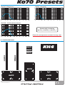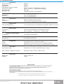
1
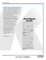
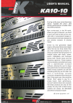
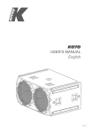
USER'S MANUAL
ENGLISH
OVERBASS
Ko70
SAFETY INSTRUCTIONS
CAUTION
This symbol, wherever it appears, alerts you to
important operating and maintenance istructions in
the accompanying literature. Read the manual!
Detailed Safety and Operation Instructions:
All the operation instructions and safety should be read before the machine is operated.
Follow instructions:
All operation and user instructions should be followed by the user or the installer.
Retain Instructions:
The safety and operating instructions should be carefully retained for future reference.
Heed Warnings:
All warnings on the machine and in the operating instructions should be adhered to.
Water and Moisture:
The machine should not be used near water or in place full of moisture.
Ventilation:
The machine should be placed so that its location does not interfere with its proper ventilation. For example, the
appliance should not be situated on a bed, carpet, or similar surface that may create an obstacle for the ventilation
openings: or placed in a built-in installation, such as a bookcase or cabinet that may impede the flow of air around the
machine.
Heat:
The machine should be situated far away from heat sources such as heat registers, radiators, stoves, or other
machines (including amplifiers) that produce heat.
Power-Cord Protection:
Power supply cord should be routed so that it is not likely to be walked on or pinched by items placed upon or against it,
paying particular attention to cords.
Cleaning:
The machine should be cleaned only as recommended by the manufacturer.
Object and Liquid Entry:
Care should be taken so that objects do not fall and liquids are not spilled into the enclosure through openings, do not
leave bottles or cans upon the unit.
Damages that Require Service:
The unit should be serviced by qualified service personnel in the following cases:
1. The external power cord or the plug has been damaged.
2. The enclosure of the unit has been damaged.
3. The unit has been exposed to water or moisture.
4. The unit does not appear to operate normally or exhibits a marked change in performance.
5. Objects have fallen, or liquid has been spilled into the unit.
Servicing:
The user should not attempt to service the unit beyond what is described in the Operating Instructions. All other
servicing should be referred to qualified and authorized service personnel.
USER'S MANUAL
P. 1
TABLE OF CONTENTS
1
INTRODUCTION
p. 03
2
AC Power Distribution
p. 04
3
Voltage Requirements
p. 04
4
Current Requirements
p. 04
5
Power connector wiring
p. 05
6
Connections
p. 05
7
Amplification & Protection circuitry
p. 05
8
DSP & REMOTE control
p. 06
9
DSP Cloner function
p. 06
10
Power supply & audio section
p. 07
11
Maintenance
p. 08
12
Accessories
p. 08
13
Physical
p. 08
14
Ko70 presets
p. 09
15
Configuration
p. 09
16
Technical data
p. 10
NOTES
p. 11
USER'S MANUAL
P. 2
1. INTRODUCTION
K-array is the new voice that sings aloud, "outside
the chorus", and whose performance is better than
any other products. Born on-the-road, in the PA
world, where you get no discount, you have to give
your best as fast as you can, often with a
"compressed" budget, K-Array systems have been
designed to give precise answers to precise
needs. K-Array systems are driven by new
generation digital engines, with
power/dimension/weight ratios that are ten
times better than any other professional
products; these systems can be remotely
controlled and come with a lot of on-board
software. K-array systems can shape their
performance following your taste and
needs. Inside K-array systems you will
find something that only K-array can
offer: the best in technology, proudly
conceived, designed and produced in
Overbass
Ko70
The Ko70 is a self-powered high
o u t p u t s u b w o o f e r. I t h a s a n
incredible reserve of power that
ensures
very
high
pressure
Italy. If they were cars, they would be
maintaining the sound quality
Ferrari. Don't agree to pay for a
constant. The Ko70 is ideal for
simple brand, claim performance,
medium and big live applications,
and don't believe those who
especially on touring P.A. systems.
maintain that these products are
The Ko70 is designed to easily
only for few people, the only truth
integrate with others K-array
is that K-array systems are
products, for example with KH4 or
unique, but affordable and within
KH15 line array satellites.
The Ko70 can be used also with
everybody's reach!
KS4 , to make a very directional
high power subwoofer.
The Ko70 uses two 21" inches very
HP Sound Equipment
high excursion cone drivers for very
low frequencies with 6" voice coil,
powered by two power amplifier
channels, each one of 3500 watt
RMS. The woofers are mounted in a
box that ensures high rigidity and
resistance to vibrations.
The transducers of Ko70 are
driven by an internal DSP module, a
dedicated remote control software
allows to control the speaker from
PC. All the Ko70 components are
designed by K-array R&D
department and custom made under
K-array control quality
system .
USER'S MANUAL
P. 3
2. AC POWER DISTRIBUTION
All amplifier modules and the rest of the audio equipment connected to it (mixing consoles, processors, etc.) must be connected to
the AC power distribution in a proper way, preserving AC line polarity and connecting earth ground such that all grounding points
are connected to a single node or common point using the same cable gauge as the neutral and line(s) cables. Bad grounding
connections between speakers and the rest of the audio system may produce noise, hum and/or serious damage to the input/output
stages in the system’s electronic equipment.
CAUTION
Before applying AC to any K-array self-powered speaker, be
sure that the voltage potential difference between neutral and
earth ground is less than 5 VAC.
3. VOLTAGE REQUIREMENTS
The Ko70 operates safely and without audio discontinuity if the AC voltage stays within either of two operating windows: 95-125 or
100-240 V, at 50 or 60 Hz.
WHEN YOU SWITCH ON THE UNIT:
The main power supply slowly ramps on t he green display on the user panel lights up, and the green leds on the left side lights
up flashing, indicating that the system is enabled and ready to process audio signals
CAUTION
If the Display does not illuminate or the system does not respond to
audio input after ten seconds, remove AC power immediately. Verify that
the voltage is within the proper range. If the problem persists please
contact HP Sound Equipment or an authorized service center.
NOTE
It is recommend that the supply be operated in the rated voltage windows, at
least a few volts away from the turn on/off points so that small AC voltage
variations do not cause the amplifier to cycle on and off.
4. CURRENT REQUIREMENTS
The Ko70 present a dynamic load to the AC mains, which causes the amount of current to fluctuate between quiet and loud operating
levels. Since different cables and circuit breakers heat up at varying rates, it is essential to understand the types of current ratings
and how they correspond to circuit breaker and cable specifications. The maximum continuous RMS current is the maximum RMS
current in a period of at least ten seconds. It is used to calculate the temperature increase in cables, which is used to select cables
that conform to electrical code standards. It is also used to select the cable size and gauge and the rating for slow-reacting thermal
breakers. The maximum burst RMS current is the maximum RMS current in a period of approximately one second. It is used to select
the rating for most magnetic breakers. The maximum instantaneous peak current during burst is used to select the rating for fastreacting magnetic breakers and to calculate the peak voltage drop in long AC cables according to the formula:
V pk (drop)= I pk x R (cable total)
For best performance, the AC Cable voltage drop should not exceed 10 Volts, or 10% at 115V and 5% at 230V. Use
Table 1 below as a guide when selecting cable gauge size and circuit breaker ratings for your operating voltage.
The minimum electrical service amperage required by a system of Ko70 is the sum of their maximum continuous RMS
current. We recommend allowing an additional 30% above the minimum amperage to prevent peak voltage drops at the
service entry.
Ko70 Current Rating:
Standard 16A(>10 sec) - 32A (<1 sec)
USER'S MANUAL
P. 4
5. POWER CONNECTOR WIRING CONVENTIONS
The Ko70 requires a grounded outlet. It is very important that the system be properly grounded for both safety and proper operation.
Use the following wiring diagram to create power cables and distribution systems.
CAUTION
The Ko70 require a ground connection. Always use a grounding outlet
when connecting these units.
CAUTION
Do not operate the unit if the power cables are frayed or broken.
CAUTION
Keep all liquids away from the Ko15 amplifiers to avoid hazards from electrical
shocks.
6. CONNECTIONS
The Ko70 presents a 10k ohm balanced input impedance to a three-pin XLR connector with the following connectors:
pin1 = Ground
pin2 = Signal +
pin3 = Signal -
CAUTION
Shorting an input connector pin to the case can form a ground loop
and cause hum.
Pins 2 and 3 carry the input as a differential signal; pin 2 is hot relative to pin 3, resulting in a positive pressure wave when a positive
signal is applied to pin 2. Use standard audio cables with XLR connectors for balanced signal sources. Make sure that pin 1 (shield)
is always connected on both ends of the cable.
If abnormal noises such as hiss and popping are produced by the loudspeaker, disconnect
the audio cable from the
speaker. If the noise stops, then most likely the problem is not with the loudspeaker. Check the audio cable, source, and AC power
for the source of the problem.
Audio signals can be easily-chained using the loop output connector on the user panel of the Ko70. A single source can drive
multiple Ko70 with a paralleled input loop, creating an unbuffered hard-wired loop connection. When driving multiple Ko30 in an
array, make certain that the source device can drive the total load impedance presented by the paralleled input circuit of the array.
The audio source must be capable of producing a minimum of 20 dBV (10-Vrms into 600 ohms) in order to produce the maximum peak
SPL over the operating bandwidth of the loudspeaker.
7. AMPLIFICATION AND PROTECTION CIRCUITRY
The Ko70 is powered by the K-array digital power amplifier with a total power of 3000+3000 watts. All the specific functions for the
Ko70 such as crossovers, frequency, phase response, and driver protection are determined by a DSP processor installed inside the
amplifier. All K-array loudspeakers are shipped with the drivers in correct alignment. However, if a driver needs to be replaced, make
sure the replacement is reinstalled with the correct polarity. Incorrect driver polarity impairs the system performance and may
damage the drivers.
USER'S MANUAL
P. 5
8. DSP CONTROL & REMOTE CONTROL
The Ko70 have a powerful DSP that manages all the functions of the speakers. Each system can store on board 16 preset that can be
recalled pushing the PRESET button. Once the preset will appear on the lower line of the display it will become automatically
available after few seconds. If you desire to set a preset as “default” you just need, once selected it, to keep pressed for five seconds
the PRESET button. After that, this preset will automatically be recall each time you will switch on your module. It is also possible to
remote each module by an RS485 serial port. In order to remote your system, you need to set each module on a different address, so
that, in your chain, no one module will have the same address. Two rotary encoder allow you to set the desired address number that
will appear on the top line of the display. Using the remote control software it is possible to mute each system, select a desired preset
loaded on-board or download a new preset pack.
For remote control operation please refer to REMOTE CONTROL AND SOFTWARE MANUAL in the next pages.
PRESET LOADED
RESET BUTTON
ID ADDRESS x10 / x1
PRESET SCROLL
RS485 PARALLEL CONNECTIONS
USE ONLY K-ARRAY CABLES/ADAPTERS
DO NOT CONNECT TO LAN/ETHERNET!
9. CLONER FUNCTION
It is possible to clone the entire presets bank from Speaker to Speaker without any PC connected. We will call SpeakerA
the one with the presets bank that you want clone, and SpeakerB the one that will be upgraded.
Set the SpeakerA on ID 99, will appear CLONER on the display
Keep SpeakerB on any ID number between 10 and 90.
Turn off both the speakers and connect by a RJ45 8 poles cable
Turn on the SpeakerB and after the SpeakerA
SpeakerA will start to clone, on the display will appear a cont down (00/15, 01/15, etc)
Wait till 20 seconds after 15/15
Change the ID of the SpeakerA to any other ID and turn off both Speakers
Turning on the SpeakerA check that it is on mode 16x16 and NOT 4x4.
If SpeakerA is in mode 4x4, just turn off the speaker and keep press the Preset button during the turning on
The preset are cloned to the SpeakerB
USER'S MANUAL
P. 6
10. POWER SUPPLY & AUDIO SECTION
Ko70 modules are using PowerCon connectors for power supply. It is possible, using the link connector, to have more modules on the
same power supply line. You can wire a max of 4 modules on the same line if the use of them will be within the 50% of their max power. For
full power use connect max two modules on the same power supply line.
The Audio section includes a female balanced XLR connector and a male XLR connector wired in parallel. Thanks to these connectors it
is possible to feed a module and to send the same signal to another one through the LINK connector. It is possible to connect till 30
different modules in parallel on the same balanced line (with a source of 600 ohm output impedance). A Level Control potentiometer
(PAD) allows different set levels. The ground lift switch can help to solve ground loop problems due to wrong ground wiring.
AUDIO LEVEL & GROUND LIFT
BALANCED AUDIO INPUT
BALANCED AUDIO PARALLEL LINK
GROUND CIRCUIT LOOP SWITCH
MAIN POWER SWITCH
MAIN AC POWER SUPPLY IN
MAIN AC POWER SUPPLY LINK OUT
CAUTION
Connecting more than 3 modules by RJ45 8 poles cable, the display of
the last off module will start lighting.
CAUTION
To connect high quantity of modules together by remote control, it
suggested to use K-array special 3 pole cables or XLR adapters.
USER'S MANUAL
P. 7
11. MAINTENANCE
INSPECTION AND MAINTENANCE
The K array flying systems are an assembly of mechanical devices, and are therefore subject to wear and tear over
prolonged use, as well as damage from corrosive agents, extreme impact, or inappropriate use. Such inspection
includes examination of all load-bearing components for any sign of undue wear, twisting, buckling, cracking, rusting,
or other corrosion. Metal seams and welds should be examined for any sign of separation or deformation. HP Sound
Equipment strongly recommends that written documentation be maintained on each K array flying system, noting date
of inspection, name of inspector, points of system checked, and any anomalies discovered.
CAUTION
Because of the safety issue involved, users must adopt and ad here to a schedule of regular
inspection and maintenance. In touring applications, key components must be inspected be for
each use.
REPLACEMENT PARTS
Any component found to be defective, or any safety-related component you even suspect might be defective, should be replaced
with the equivalent, approved part. Parts specific to a K array system should be ordered directly from HP Sound Equipment. No
attempt should be made to substitute what appears to be equivalent or “mostly the same” generic replacements. To the best of our
knowledge, most of these suppliers are reputable and their products are reliable. However, HP Sound Equipment has no way of
assuring the quality of products made by these various suppliers. Therefore, HP Sound Equipment is not responsible for problems
caused by components that were not supplied by HP Sound Equipment.
12. ACCESSORIES
KO -TR2 - trolley
KPIN
KO -COVER2
Protection
strong bag
13. PHYSICAL
Weight 78Kg
USER'S MANUAL
102 cm
115 c
m
60 cm
85 cm
P. 8
Ko70 Presets
Ko70F - Flat preset
Ko70I - Infra sub
Ko70D - 120 Hz enhancement
Preset with 1 mt delay
Ko70I_1, Ko70D_1, Ko70F_1
Check for new presets on www.k-array.com
15. CONFIGURATIONS
KH15
KH4
KH15
KK200
KK200
KH15
Ko70
Ko70
USER'S MANUAL
Ko70
P. 9
16. TECHNICAL DATA
Acoustics
Power handling
Max power
Impedance
Operating frequency range
Frequency range
SPL 1W/1mt
Maximum SPL
3000 w 1
8000 w 2
2x8W
30 Hz - 120 Hz +/- 3dB (preset relating) 3
20 HZ - 150 Hz +/- 3dB (preset relating) 4
99.5 dB 5
136 dB continuos - 140 dB peak 6
Coverage
Horizontal
Vertical
omni-array dependent
omni-array dependent
Cross over
Type
Frequency
DSP controlled preset relating
150 Hz max suggested (preset relating) 7
Transducers
Low - Mid frequency
2 x 21" High excursion neodymium speakers with 6" voice coil
Audio Input
Connectors
Wiring
male + female parallel 3 poles balanced XLR
Pin1 = ground / Pin2 = hot / Pin3 = cold
Remote control Input
Connectors
2 x female 8 poles RJ45
Power Input
Connectors
2 x PowerCon IN/OUT
Amplifiers
Type
Power
Protections
2 modules class D - DSP controlled
3500 watts x 2 channels on 8 ohm (7000 watt total) 8
Dynamic limiter, over current, over temp, short circuits
AC power
Operating range
Standard 100 - 240 Vac 50-60Hz (auto-range)
Max continuos and burst current
Standard 16A(>10 sec) - 32A (<1 sec)
Physical
Measures
Weight
115 x 60 x 85 cm
78 Kg
Notes for data
1. Power handling is measured following AES standard conditions: transducers driven continuously for two hours with a band-limited noise
signal having 6 dB of crest factor.
2. Max power is the maximum RMS applicable power for a musical signal, the referement signal is the one proposed by EIAJ standard.
3. Recommended maximum operating frequency range. Response depends on loading conditions and room acoustics.
4. Free field measured with 1/3 octave frequency resolution at 2 mt.
5. Measured@4 mt then scaled@1 mt.
6. Measured with audio source @1 mt.
7. This is the frequency in which the transducers produce the same sound pressure level (measured@2 mt).
8. Amplifier wattage rating is based on the maximum unclipped burst sine wave RMS voltage that the amplifier will produce into the nominal
load impedance .
New materials and design are introduced into existing products without previous notice.
Present systems may differ in some respects from those presented in this brochure.
USER'S MANUAL
P. 10
K-NOTES
K-array System - www.k-array.com
by HP Sound Equipment s.r.l.
Viale Roma 7/i 50037 San Piero a Sieve (Firenze) Italy - tel +39 055 8487222 fax +39 055 8487238 e-mail: [email protected]
USER'S MANUAL
P. 11