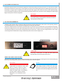
1
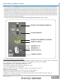
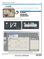
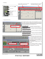
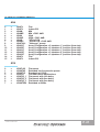
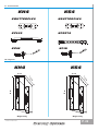
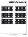
REV.04
USER'S MANUAL
ENGLISH
arr
ay
K
KH4/KS4
TABLE OF CONTENTS
1
Safety instructions
p. 5
2
AC Power Distribution
p. 6
3
Voltage Requirements
p. 6
4
Current Requirements
p. 7
5
Power connector wiring
p. 7
6
Connections
p. 8
7
Amplification and protection circuitry
p. 8
8
DSP & REMOTE control
p. 9
9
REMOTE control software
p. 10
10
Power supply & audio section
p. 15
11
System configurations
p. 16
11.1 System coverage
p. 17
11.2 Short installation manual
p. 17
12
System configurations on floor
p. 18
13
Variable vertical coverage
p. 18
14
Suspending manual
p. 19
15
Maintenance
p. 20
16
Default speaker presets
p. 21
17
Accessories
p. 22
18
Physical
p. 22
KH4 Presets
p. 23
KS4 Presets
p. 24
Polar response
p. 25
KH4 Technical data
p. 27
KS4 Technical data
p. 29
USER'S MANUAL
P. 3
1. SAFETY INSTRUCTIONS
CAUTION
!
This symbol, wherever it appears, alerts you to
important operating and maintenance istructions in
the accompanying literature. Read the manual!
• To reduce the risk of electric shock, disconnect the amplifier from the AC mains before
installing audio cable. Reconnect the power cord only after making all signal connections.
• Connect the amplifier to a two-pole, three wire grounding mains receptacle. The
receptacle must be connected to a fuse or circuit breaker. Connection to any other type of
receptacle poses a shock hazard and may violate local electrical codes.
• Do not install the amplifier in wet or humid locations without using weather protection.
• Do not allow water or any foreign object to get inside the amplifier. Do not put objects
containing liquid on, or near, the unit.
• To reduce the risk of overheating the amplifier, avoid exposing it to direct sunlight. Do
not install the unit near heat emitting appliances, such as a room heater or stove.
• The amplifier should be placed so that its location does not interfere with its proper
ventilation. For example, the appliance should not be situated on a bed, carpet, or similar
surface that may create an obstacle for the ventilation openings.
• This amplifier contains potentially hazardous voltages. Do not attempt to disassemble
the unit. The unit contains no user serviceable parts. Repairs should be performed only by
factory trained service personnel.
USER'S MANUAL
P. 5
2. AC POWER DISTRIBUTION
All amplifier modules and the rest of the audio equipment connected to it (mixing consoles, processors, etc.) must be connected to
the AC power distribution in a properway, preserving AC line polarity and connecting earth ground such that all grounding points are
connected to a single node or common point using the same cable gauge as the neutral and line(s) cables. Bad grounding
connections between speakers and the rest of the audio system may produce noise, hum and/or serious damage to the input/output
stages in the system’s electronic equipment.
CAUTION
!
Before applying AC to any K-array self-powered speaker, be
sure that the voltage potential difference between neutral and
earth ground is less than 5 VAC.
3. VOLTAGE REQUIREMENTS
The KH4 or KS4 operates safely and without audio discontinuity if the AC voltage stays within either of two operating windows:
95-125 (voltage selector on 115 V) or 195-250 V (voltage selector on 230 V), at 50 or 60 Hz.
The device is default set to be connected to 230 V AC Power. To use the device on a 115 V AC Power you need, before connecting it,
to move the voltage selector's cover, just loosening the two screws, and to choose the correct use voltage by the red switch. Be
sure that both voltage set on the selector and AC Power have the same value . Always close the voltage selector's cover before
connecting the device to AC Power. Change the label that points out the correct voltage in use.
115-230
CAUTION
!
Connecting a 115V system on a 230V AC Power causes heavy
damages to the device and serious risk for users .
WHEN YOU SWITCH ON THE UNIT:
The main power supply slowly ramps on t he green display on the user panel lights up, and the green leds on the left side lights
up flashing, indicating that the system is enabled and ready to process audio signals
!
CAUTION
NOTE
If the Display does not illuminate or the
It is recommend that the supply be operated in the
system does not respond to audio input
rated voltage windows, at least a few volts away
after ten seconds, remove AC power
from the turn on/off points so that small AC voltage
immediately. Verify that the voltage is
variations do not cause the amplifier to cycle on and
within the proper range. If the problem
off.
persists please contact HP Sound
Equipment or an authorized service
center.
USER'S MANUAL
P. 6
4. CURRENT REQUIREMENTS
The KH4 or KS4 presents a dynamic load to the AC mains, which causes the amount of current to fluctuate between quiet and loud
operating levels. Since different cables and circuit breakers heat up at varying rates, it is essential to understand the types of current
ratings and how they correspond to circuit breaker and cable specifications. The maximum continuous RMS current is the maximum
RMS current in a period of at least ten seconds. It is used to calculate the temperature increase in cables, which is used to select
cables that conform to electrical code standards. It is also used to select the cable size and gauge and the rating for slow-reacting
thermal breakers. The maximum burst RMS current is the maximum RMS current in a period of approximately one second. It is used
to select the rating for magnetic breakers. The maximum instantaneous peak current during burst is used to select the rating for
fast-reacting magnetic breakers
For best performance, the AC Cable voltage drop should not exceed 10% at 115V and 5% at 230V.
The minimum electrical service amperage required by a system of KH4 or KS4 is the sum of their maximum
continuous RMS current. We recommend allowing an additional 30% above the minimum amperage to prevent peak
voltage drops at the service entry.
KH4 and KS4 Current Rating:
115
230
115
230
VAC
VAC
VAC
VAC
=
=
=
=
20A Max Continuous RMS
10A Max Continuous RMS
I. Nom 7.2A
I. Nom 4.4A
5. POWER CONNECTOR WIRING CONVENTIONS
The KH4 or KS4 requires a grounded outlet. It is very important that the system be properly grounded for both safety and proper
operation.
CAUTION
!
!
The KH4 or KS4 requires a ground connection.
CAUTION
Do not operate the unit if the power cables are frayed or broken.
CAUTION
!
USER'S MANUAL
Keep all liquids away from the KH4 or KS4 amplifiers to avoid hazards from
electrical shocks.
P. 7
6. CONNECTIONS
The KH4 or KS4 presents a 10k ohm balanced input impedance to a three-pin XLR connector with the following
connectors:
pin1 = Ground
pin2 = Signal +
pin3 = Signal -
CAUTION
!
Shorting an input connector pin to the case can form a ground loop
and cause hum.
Use standard audio cables with XLR connectors for balanced signal sources. Make sure that pin 1 (shield) is always connected on
both ends of the cable.
If abnormal noises such as hiss and popping are produced by the loudspeaker, disconnect
the audio cable from the
speaker. If the noise stops, then most likely the problem is not with the loudspeaker. Check the audio cable, source, and AC power
for the source of the problem.
Audio signals can be easy-chained using the loop output connector on the user panel of the KH4 or KS4. A single source can drive
multiple KH4 or KS4 with a paralleled input loop, creating an unbuffered hard-wired loop connection. When driving multiple KH4 or
KS4 in an array, make certain that the source device can drive the total load impedance presented by the paralleled input circuit of the
array. The audio source must be capable of producing a minimum of not distorted 20 dBV (10-Vrms into 600 ohms). The maximum
peak SPL over the operating bandwidth of the loudspeaker is generated by +4dB input signal (1.230 V. RMS).
7. AMPLIFICATION AND PROTECTION CIRCUITRY
The KH4 or KS4 is powered by the K-array power amplifiers, a high-power eight-channel digital amplifiers (500 watts/ch. RMS) with a
total power of 4000 watts. All the specific functions for the KH4 or KS4 such as crossovers, frequency, phase response, and driver
protection are determined by a DSP processor installed inside the amplifier. All K-array loudspeakers are shipped with the drivers in
correct alignment. However, if a driver needs to be replaced, make sure the replacement is reinstalled with the correct polarity.
Incorrect driver polarity impairs the system performance and may damage the drivers.
USER'S MANUAL
P. 8
8. DSP CONTROL & REMOTE CONTROL
KH4 and KS4 have a powerful DSP that manages all the functions of the speakers. Each system can store on board 16 preset that
can be recalled pushing the PRESET button. Once the preset will appear on the lower line of the display it will become automatically
available after few seconds. If you desire to set a preset as “default” you just need, once selected it, to keep pressed for five seconds
the PRESET button. After that, this preset will automatically be recall each time you will switch on your module. It is also possible to
remote each module by an RS485 serial port. In order to remote your system, you need to set each module on a different address, so
that, in your chain, no one module will have the same address. Two rotary encoders allow you to set the desired address number that
will appear on the top line of the display. Using the remote control software it is possible to mute each system, select a desired preset
loaded on-board or download a new preset pack.
For remote control operation please refer to REMOTE CONTROL AND SOFTWARE MANUAL in the next pages.
FROM PC OR PREVIOUS MODULE
TO NEXT MODULE
ID 39
KH4FL01
ADDRESS FOR REMOTE CONTROL
PRESET LOADED
ADDRESS X 10
ADDRESS X 1
RESET BUTTON
PRESET SCROLL
8.1 Cloner function & preset systems
It is possible to clone the entire presets bank from Speaker to Speaker without any PC connected. We will call SpeakerA
the one with the presets bank that you want clone, and SpeakerB the one that will be upgraded.
Set the SpeakerA on ID 99, will appear CLONER on the display
Keep SpeakerB on any ID number between 10 and 90.
Turn off both the speakers and connect by a RJ45 8 poles cable
Turn on the SpeakerB and after the SpeakerA
SpeakerA will start to clone, on the display will appear a cont down (00/15, 01/15, etc)
Wait till 20 seconds after 15/15
Change the ID of the SpeakerA to any other ID and turn off both Speakers
Turning on the SpeakerA check that it is on mode 16x16 and NOT 4x4.
If SpeakerA is in mode 4x4, just turn off the speaker and keep press the Preset button during the turning on
The preset are cloned to the SpeakerB
USER'S MANUAL
P. 9
9. REMOTE CONTROL SOFTWARE
1 . To connect the K-array modules to a PC, it is needed a RS485-USB adapter, we recommend the K-USB adapter (pic.1).
K-USB
USB to RS485 adapter
Connect the K-usb to a PC and install the drivers required included in the CD-ROM.
SYSTEM REQUIREMENTS
Operating systems:
Win98/98SE/Me/2000/XP/Vista
1
Minimum requirements:
CPU
300 MHz
RAM
128 Mb
Recommended requirements:
RAM
512 Mb
2 . Install the K array control software from installer in the CD-ROM
2.1 Start the Karray_manager_V2 from Windows - Start - Software - Karray_manager_V2
2.2 Click on NO when ask for demo mode start
2.3 Click on System - Settings to configure which COM port use, the COM port of K-USB, usually is the higher number.
If you don't find, you can check it on windows-control panel-system-hardware-COM Port
USER'S MANUAL
P. 10
3 . ID setting
On this bars you can see all the
Pressing this button you can have a
modules connected in your net.
refresh of the modules connected.
FROM PC OR PREVIOUS MODULE
TO NEXT MODULE
ID 39
KH4FL01
ADDRESS FOR REMOTE CONTROL
PRESET LOADED
ADDRESS X 10
ADDRESS X 1
RESET BUTTON
PRESET SCROLL
4 . Single module control
This frame describes the state of all the loudspeakers on the net.
The colour of the little rectangles into this frame represents the
status of the loudspeakers. Each loudspeaker has three rectangles.
Here there is the meaning of the rectangle's colour.
Click once on the ID module
Two rectangles on top:
that you want control.
Both rectangles grey: the loudspeaker is not present on the net.
Temperature rectangle red: one module inside that loudspeaker is
over-temperature.
Temperature rectangle green: all modules inside that loudspeaker
have a good temperature.
Protection/Fail rectangle red: at least one module inside that
loudspeaker is in protection.
Temperature rectangle green: all modules inside that loudspeaker
are working properly.
Temperature rectangle black: if this rectangle is black it means that
the loudspeaker is not responding.
The main causes of this malfunction are
loss of power supply and loss of serial
connection between the hub and the
loudspeaker. Check the hardware. If
this rectangle is black will be black also
the Protection/Fail.
Protection/Fail rectangle black: see
Module status panel
Preset slots on the
above.
The remaining rectangle: Is related to
the mute function; if red, the related
loudspeaker is in "mute" status.
USER'S MANUAL
P. 11
Module status panel
Preset names, you can change it
Store the active preset to default
from the area on the right
when restart the module
Mute Module
Select the preset number, write
the
name,
maximum
Module details
5
characters, press the Send
With this button, you can load presets from PC to the
button
module, you have to press, choose the slot that you
want use and select the .EQS file that you want to
load.
5. Mute groups
On the Mute Groups window, you can manage the modules Mute as groups, up to 4 different.
5.1
Choose the modules from the list on the right
Press the right arrow of the group that you prefer, to add the modules
5.2 It is possible to assign names to the groups, just writing in the fields.
USER'S MANUAL
P. 12
6. Preset groups
On the Preset Groups window, you can manage the modules Presets as groups, up to 4 different.
6.1
Choose the modules from the list on the right
Press the right arrow of the group that you prefer, to add the modules
Select the number of the preset you want to choose, after press Change button
6.2 It is possible to assign names to the groups, just writing in the fields.
7. Text editor
It is available a text editor on the software, it can manages .RTF files.
USER'S MANUAL
P. 13
8. Master Mute control
It is possible to Mute all the modules connected just pressing Master Mute button.
To protect from accidental pressing of this button, you will need to Unlock by pressing the Unlock button below it.
9. Exit option
When you choose to exit from the software, will appear an alert window that alert you about Unmuting all the modules
connected, this is important because the Mute function is controlled only by software.
10. Save and Load
It is possible to save the speakers configuration for Mute and Preset Groups, just Save a .CONF file.
It is possible to use XLR adapters for connections, here below, the connection schematic.
1
2
3
1 2 3 4 5 6 7 8
USER'S MANUAL
brown
white orange
green
white green
white blue
blue
1
1
2
2
3
3
P. 14
10. POWER SUPPLY & AUDIO SECTION
KH4 and KS4 modules are using PowerCon connectors for power supply. It is possible, using the link connector, to have more modules
on the same power supply line. Pay attention to not exceed the maximum powercapability of PowerCon connectors. The Audio section
includes a female balanced XLR connector and a male XLR connector wired in parallel. Thanks to these connectors it is possible to feed
a module and to send the same signal to another one through the LINK connector. It is possible to connect till 30 different modules in
parallel on the same balanced line (with a source of 600 ohm output impedance). A Level Control potentiometer (PAD) allows different
set levels. The ground lift switch can help to solve ground loop problems separating loudspeaker groud from signal cable's ground.
MAIN POWER SWITCH
MAIN AC POWER SUPPLY IN
MAIN AC POWER SUPPLY LINK OUT
KH4/KS4 max 6A
AUDIO LEVEL
GROUND CIRCUIT LOOP SWITCH
BALANCED AUDIO INPUT
BALANCED AUDIO PARALLEL LINK
USER'S MANUAL
P. 15
11. SYSTEM CONFIGURATION
0°
5°
10°
0°
5°
DS 5
10°
5°
DS 5
DS 5
DS 5
DS = driver slide
DS 7
10°
5°
0°
DS 5
10°
DS 7
DS 3
DS 3
KH4
DS 10
DS 10
DS 10
WARNING
!
Do not assemble more than 6 frame in the same array
KH4 System Spl calculations
System
2 x KH4 + 4 x KS4
4 x KH4 + 8 x KS4
6 x KH4 + 12 x KS4
Vert. Coverage
From 7° to 37°
From 7° to 47°
From 7° to 57°
System
2 x KH4 + 4 x KS4
4 x KH4 + 8 x KS4
6 x KH4 + 12 x KS4
SPL @ 10mt SPL @ 20mt SPL @ 40mt SPL @ 80mt
128dB
124dB
118dB
112dB
134dB
130dB
124dB
118dB
138dB
134dB
128dB
122dB
K4BUTTERFLY
K4TILTER
Rotation point
5
KPIN
Array tilt points 1 - 6
to set the general array tilt
Rotation point
0
-10
5
-10
0
10
10
Rotation point
Tilt degrees settings
set the same value on each speaker for the
right tilt angle
USER'S MANUAL
SPL @1mt
140dB +/- 3dB
146dB +/- 4dB
150dB +/- 6dB
Fixing point
P. 16
11.1 SYSTEM COVERAGE
System 6 x KH4 + 12 KS4
System 4 x KH4 + 8 KS4
160
150
150
150
140
140
140
130
130
120
120
110
110
100
10
20
30
40
50
DISTANCE mt
60
70
80
dB
SPL
160
dB
SPL
dB
SPL
System 2 x KH4 + 4 KS4
160
100
130
120
110
10
20
30
40
50
DISTANCE mt
60
70
80
100
10
20
30
40
50
DISTANCE mt
60
70
11.2 SHORT INSTALLATION MANUAL
KS4 with K4Feet
KS4 with K4Butterfly
KH4 with K4Butterfly and K4Tilter
USER'S MANUAL
P. 17
80
12. SYSTEM CONFIGURATION on the floor
DS 10
DS 10
KH4
-10°
DS 10
-10°
DS 5
KS4
-10°
KS4
KH4
-10°
KS4
-10°
KS4
KS4
-10°
KS4
KS4
For floor applications you can set up a maximum of 3 speakers each K-feet4
For flying applications you can append a maximum of 4 KH4 each K-fly4
13. VARIABLE VERTICAL COVERAGE
The KH4 is equipped with 2 driver slides. So that you can set up the preferred vertical coverage of the speaker.
7°
USER'S MANUAL
37°
P. 18
14. SUSPENDING MANUAL
CAUTION
Please read this statement carefully and in its entirety. It contains important information regarding
!
safety issues, including guidelines for general safe use of rigging systems as well as advisories on
government regulations and liability laws.
SCOPE OF THIS MANUAL
Although this manual contains much useful information on rigging in general, it does not claim to be a comprehensive
resource on the subject. This manual assumes that the owners and/or users of a K-array System are knowledgeable
and experienced in the areas of rigging and flying loudspeaker systems.
MANY ISSUES OF CRUCIAL CONCERN, SUCH AS THE DETERMINATION OF APPROPRIATENESS AND CONDITION OF
VENUE RIGGING POINTS, CANNOT BE ADDRESSED HERE. THEREFORE, THE USER MUST ASSUME ALL
RESPONSIBILITY FOR THE APPROPRIATE USE OF K-ARRAY SYSTEMS IN ANY PARTICULAR LOCATION OR
CIRCUMSTANCE.
The suspension of large, heavy objects in public places is subject to numerous laws and regulations at the
national/federal, state/provincial, and local levels. This manual does not address the specifics of any such applicable
laws and government regulations. This manual details procedures and practices consistent with those generally
acknowledged as allowable and safe in Europe. However, the user must assume responsibility for making sure that
use of any K-array system and its components in any particular circumstance or venue conforms to all applicable
laws and regulations in force at the time.
REGULATORY COMPLIANCE
The design and safe working load ratings of the K-array system, unless otherwise specified, are based on either a 5:1
or 7:1 safety factor. However there are wide variations internationally in the regulations and practices applying to
suspension of sound systems in public places. Government officials in one location may have a stricter interpretation
than another local official, even when operating under the same regulations and in the same legal jurisdiction.
CONSEQUENTLY, USERS OF K-array RIGGING SYSTEMS SHOULD BE PREPARED TO TAKE ADDITIONAL SAFETY
ASSURANCE MEASURES BEYOND THOSE OUTLINED IN THIS MANUAL. IN ALL CASES, IT IS THE RESPONSIBILITY OF
THE USER TO MAKE CERTAIN THAT ANY K-array LOUDSPEAKER SYSTEM IS SUSPENDED IN ACCORDANCE WITH ALL
APPLICABLE NATIONAL/FEDERAL, STATE/PROVINCIAL, AND LOCAL REGULATIONS. SAFETY RESPONSIBILITIES
“ABOVE THE HOOK”
In most touring applications of rigging systems, the touring sound provider is normally responsible for ensuring the
safety of the suspension system only below the attachment point. The safety and suitability of the attachment point is
generally seen as the responsibility of the venue owner or operator. However, this distinction (“above the hook”
versus “below the hook”) can be open to interpretation. Touring system operators should double-check to make
certain that attachment points are approved and suitably load rated, and that the points used are those identified as
such by the venue owner or operator.
CAUTION
!
As an extra precaution, careful inspection of the attachment points is advised before
flying, particularly in older venues or those hosting frequent events using large sound
and lighting systems.
In any case, K-array systems are intended only for suspension from approved rigging points, each known to have
ample safe working loads margins for the system components suspended below them.
USER'S MANUAL
P. 19
15. MAINTENANCE
INSPECTION AND MAINTENANCE
The K array flying systems are an assembly of mechanical devices, and are therefore subject to wear and tear over
prolonged use, as well as damage from corrosive agents, extreme impact, or inappropriate use. Such inspection
includes examination of all load-bearing components for any sign of undue wear, twisting, buckling, cracking, rusting,
or other corrosion. Metal seams and welds should be examined for any sign of separation or deformation. HP Sound
Equipment strongly recommends that written documentation be maintained on each K array flying system, noting date
of inspection, name of inspector, points of system checked, and any anomalies discovered.
CAUTION
!
Because of the safety issue involved, users must adopt and ad here to a schedule of regular
inspection and maintenance. In touring applications, key components must be inspected be for
each use.
REPLACEMENT PARTS
Any component found to be defective, or any safety-related component you even suspect might be defective, should be replaced
with the equivalent, approved part. Parts specific to a K array system should be ordered directly from HP Sound Equipment. No
attempt should be made to substitute what appears to be equivalent or “mostly the same” generic replacements. To the best of our
knowledge, most of these suppliers are reputable and their products are reliable. However, HP Sound Equipment has no way of
assuring the quality of products made by these various suppliers. Therefore, HP Sound Equipment is not responsible for problems
caused by components that were not supplied by HP Sound Equipment.
USER'S MANUAL
P. 20
16. DEFAULT SPEAKERS PRESETS
KH4
0
1
2
3
4
5
6
7
8
9
10
11
12
13
14
15
=
=
=
=
=
=
=
=
=
=
=
=
=
=
=
=
KH4FL
KH4FL
KH4M
KH4MP
KH4H
KH4HP
KH4Q
KH4QP
KH4FULL
KH421F
KH422F
KH431F
KH432F
KH433F
KH4FL
KH4FL
Flat
Indoor EQ
Mid
Mid + PAD -4dB
High
High + PAD -4dB
"Hi-Hat" EQ
"Hi-Hat" EQ + PAD -4dB
"fullrange" preset
Array Configuration x 2 speakers 1° position (from top)
Array Configuration x 2 speakers 2° position (from top)
Array Configuration x 3 speakers 1° position (from top)
Array Configuration x 3 speakers 2° position (from top)
Array Configuration x 3 speakers 3° position (from top)
Flat
Indoor EQ
KS4FL02
KS4XT45
KS4XT12
KS4101
KS4F02_1
KS4F02_2
KS4F02_3
KS4XT200
Flat preset
Extended low frequencies preset
Emphasis at 120Hz
For stand alone applications
Flat preset with 1ms delay
Flat preset with 2ms delay
Flat preset with 3ms delay
Extended at 200Hz
KS4
0
1
2
3
4
5
6
7
=
=
=
=
=
=
=
=
USER'S MANUAL
P. 21
17. Accessories
KH4
KS4
KBUTTERFLY4
KBUTTERFLY4
BASE
0
-10
10
5
-10
0
5
5
0
BASE
BASE
-10
5
0
10
10
10
-10
BASE
KFEET4
KFLY4
KPIN
KPIN
18. Physical
KH4
KS4
16 cm
16 cm
2
11
2
11
60 cm
60 cm
cm
cm
Weight 47Kg
USER'S MANUAL
Weight 37Kg
P. 22
KH4 Presets
KH4FL - Flat preset
KH4FL02
KH4M01
KH4H01
KH4Q
KH4FULL
USER'S MANUAL
P. 23
KS4 Presets
KS4FL - Flat preset
KS4XT45
KS4XT12
KS4101
KS4XT200
USER'S MANUAL
P. 24
KH4 polar response
HORIZONTAL COVERAGE
USER'S MANUAL
VERTICAL COVERAGE
Close
VERTICAL COVERAGE
Open
P. 25
K-NOTES
Speakers power handling
KH4
8 KHz
Acoustics
1 KHz
500 Hz
3600 w + 400 w (AES)
250 Hz
Max Power
5000 w + 700 w 1
Impedance
6 x 4Ω + 1 x 8Ω + 1 x 6Ω
Full frequency range
SPL 1W/1mt
Maximum SPL
4 KHz
Vertical
60°
150°
30°
80 HZ - 20 KHz.
105 dB (low-mid) + 113 dB (high 1) + 114 dB (high 2) 2
back
133 dB continuous - 139 dB peak
Coverage
Horizontal
90°
120°
180°
0°
-30°
-150°
120°
-60°
-120°
mechanically variable from 7° to 37°
-90°
Cross over
Type
Frequency
horizontal
DSP controlled
8 KHz
1.2 KHz
4 KHz
Transducers
Low - Mid frequency
High frequency
Wiring
1 KHz
500 Hz
250 Hz
12 x 8” Neodymium speakers with 2.5” voice coil
90°
5 x 1” Neodymium planar wave drivers with 1.75” voice coil
Audio Input
Connectors
front
120°
0°
60°
150°
30°
male + female parallel 3-pin balanced XLR
Pin1 = ground / Pin2 = hot (+) / Pin3 = cold (-)
back
180°
0°
front
Remote control Input
Connectors
2 x female 8-pin RJ45
Power Input
Connectors
Type
Power
Protection
-30°
-150°
-90°
4 modules class D - DSP controlled
90°
500 watts x 8 channels at 4 ohms (4000 watt total) 3
Dynamic limiter, over current, over temp, short circuits
-60°
-120°
2 x PowerCon IN/OUT
120°
5°
60°
150°
30°
AC power
Operating range
I.nom
Minimum operation voltage
Maximum operation voltage
Max continuous
and burst curren
210 - 240 Vac 50Hz (default)100 - 120 Vac 60Hz (selectable)
back
180°
0°
front
7.2 A / 115 Vac - 4.4 A / 230 Vac
95 - 195 Vac
-30°
-150°
125 - 250 Vac
-60°
-120°
(Default) 12A(>10 sec) - 24A (<1 sec)
(Selectable) 20A(>10 sec) - 40A (<1sec)
-90°
Physical
Dimensions
Weight
max 117 x 60 x 16,5 cm (46,34” x 23.62” x 6.5”)
90°
120°
51 Kg (113.32 lbs)
Notes for data
1. Maximum RMS applicable power for a musical signal, the reference signal is the
one proposed by EIAJ standard.
2. Measured @4 mt then scaled @1 mt
New materials and design are introduced into existing products without previous
notice. Present systems may differ in some respects from those presented in
this brochure.
10°
back
60°
150°
30°
180°
0° front
-30°
-150°
-60°
-120°
-90°
vertical
P. 26
P.
28
KS4
Acoustics
Speakers power handling
4000 W
Maximum power
6000 w 1
Impedance
8 x 4Ω
Frequency range
Accessories:
•
•
30 Hz - 150 KHz
SPL 1W/1mt
Maximum SPL
(AES)
103 dB 2
•
132 dB continuous - 138 dB peak (measured with 6 units, related to 1)
Coverage
Horizontal
dipole 120°
Vertical
dipole 120°
Crossover
Type
DSP controlled
Frequency
•
K-CASE3: Flight-Case for K modules
(3pcs of KH4/KS4 or 2pcs of KS4/KH4 + 4pcs KH15)
K-CASE2: Flight-Case for K modules
(2pcs of KH4/KS4 or 1pcs of KS4/KH4 + 4pcs KH15)
K-CASE1: Flight-Case for K modules
(1pcs of KH4/KS4 or 4pcs KH15)
K-FEET: Feet Kit for ground stacking
applications
•
K-FLY4: Flying bar for
•
K-FLY4/15: Flying bar for
applications
KH15
units under KH4/KS4 cluster
low pass @150 Hz
Transducers
8 x 10” High excursion neodymium speakers with 2” voice coil
Audio Input
Connectors
Wiring
male + female parallel 3-pin balanced XLR
Pin1 = ground / Pin2 = hot (+) / Pin3 = cold (-)
Remote control Input
Connectors
2 x female 8-pin RJ45
Power Input
Connectors
2 x PowerCon IN/OUT
Type
Power
Protection
4 modules class D - DSP controlled
500 watts x 8 channels at 4 ohms (4000 watt total)3
Dynamic limiter, over current, over temp, short circuits
AC power
Operating range
210 - 240 Vac 50Hz (default)
100 - 120 Vac 60Hz (selectable)
I. nom
7.2 A / 115 Vac - 4.4 A / 230 Vac
Minimum operation voltage
95 - 195 Vac
Maximum operation voltage
Max continuous and burst
current
125 - 250 Vac
Default 12A(>10 sec) - 24A (<1 sec)
Selectable 20A(>10 sec) - 40A (<1sec)
Physical
Dimensions
max 117 x 60 x 16.5 cm (46.34” x 23.62” x 6.50”)
Weight
46.8 Kg (103.18 lbs)
Notes for data
1. Maximum RMS applicable power for a musical signal, the reference
signal is the one proposed by EIAJ standard.
2. Measured @4 mt then scaled @1 mt
impedance.
New materials and design are introduced into existing products without
previous notice. Present systems may differ in some respects from
those presented in this brochure.
P. 29
K-array - www.k-array.com
by HP Sound Equipment s.r.l.
Viale Roma 7/i 50037 San Piero a Sieve (Firenze) Italy - tel +39 055 8487222 fax +39 055 8487238 e-mail: [email protected]