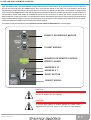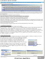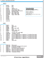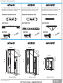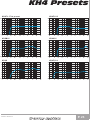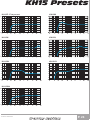
1
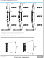
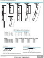
USER'S MANUAL
ENGLISH
K Array Line
KH4/KS4/KH15
SAFETY INSTRUCTIONS
CAUTION
This symbol, wherever it appears, alerts you to
important operating and maintenance istructions in
the accompanying literature. Read the manual!
Detailed Safety and Operation Instructions:
All the operation instructions and safety should be read before the machine is operated.
Follow instructions:
All operation and user instructions should be followed by the user or the installer.
Retain Instructions:
The safety and operating instructions should be carefully retained for future reference.
Heed Warnings:
All warnings on the machine and in the operating instructions should be adhered to.
Water and Moisture:
The machine should not be used near water or in place full of moisture.
Ventilation:
The machine should be placed so that its location does not interfere with its proper ventilation. For example, the
appliance should not be situated on a bed, carpet, or similar surface that may create an obstacle for the ventilation
openings: or placed in a built-in installation, such as a bookcase or cabinet that may impede the flow of air around the
machine.
Heat:
The machine should be situated far away from heat sources such as heat registers, radiators, stoves, or other
machines (including amplifiers) that produce heat.
Power-Cord Protection:
Power supply cord should be routed so that it is not likely to be walked on or pinched by items placed upon or against it,
paying particular attention to cords.
Cleaning:
The machine should be cleaned only as recommended by the manufacturer.
Object and Liquid Entry:
Care should be taken so that objects do not fall and liquids are not spilled into the enclosure through openings, do not
leave bottles or cans upon the unit.
Damages that Require Service:
The unit should be serviced by qualified service personnel in the following cases:
1. The external power cord or the plug has been damaged.
2. The enclosure of the unit has been damaged.
3. The unit has been exposed to water or moisture.
4. The unit does not appear to operate normally or exhibits a marked change in performance.
5. Objects have fallen, or liquid has been spilled into the unit.
Servicing:
The user should not attempt to service the unit beyond what is described in the Operating Instructions. All other
servicing should be referred to qualified and authorized service personnel.
USER'S MANUAL
P. 1
TABLE OF CONTENTS
1
INTRODUCTION
p. 3
2
AC Power Distribution
p. 4
3
Voltage Requirements
p. 4
4
Current Requirements
p. 5
5
Power connector wiring
p. 5
6
Connections
p. 6
7
Amplification & protection circuitry
p. 6
8
DSP & REMOTE control
p. 7
9
DSP & REMOTE control software
p. 8
10
Power supply & audio section
p. 14
11
System configurations
p. 15
11.1 System coverage
p. 16
11.2 Short installation manual
p. 16
12
System configurations on floor
p. 17
13
Variable vertical coverage
p. 17
14
System configurations (KH15)
p. 18
15
Suspending manual
p. 19
16
Maintenance of the system
p. 20
17
Default speaker presets
p. 21
18
Details & Accessories
p. 22
19
Physical
p. 22
KH4 Presets
p. 23
KH15 Presets
p. 24
KS4 Presets
p. 25
Polar response
p. 26
NOTES
p. 27
USER'S MANUAL
P. 2
1. INTRODUCTION
K-array is the new voice that sings aloud, "outside
the chorus", and whose performance is better than
any other products. Born on-the-road, in the PA
world, where you get no discount, you have to give
your best as fast as you can, often with a
"compressed" budget, K-Array systems have been
designed to give precise answers to precise needs.
K-Array systems are driven by new generation digital
engines, with power/dimension/weight ratios that are
ten times better than any other professional
products; these systems can be remotely controlled
and come with a lot of on-board software. K-array
systems can shape their performance following your
taste and needs. Inside K-array systems you will find
something that only K-array can offer: the best in
technology, proudly conceived, designed and produced
in Italy. If they were cars, they would be Ferrari. Don't
agree to pay for a simple brand, claim performance,
and don't believe those who maintain that these
products are only for few people, the only truth is that
K-array systems are unique, but affordable and within
everybody's reach!
HP Sound Equipment
USER'S MANUAL
P. 3
2. AC POWER DISTRIBUTION
All amplifier modules and the rest of the audio equipment connected to it (mixing consoles, processors, etc.) must be connected to
the AC power distribution in a properway, preserving AC line polarity and connecting earth ground such that all grounding points are
connected to a single node or common point using the same cable gauge as the neutral and line(s) cables. Bad grounding
connections between speakers and the rest of the audio system may produce noise, hum and/or serious damage to the input/output
stages in the system’s electronic equipment.
CAUTION
Before applying AC to any K-array self-powered speaker, be
sure that the voltage potential difference between neutral and
earth ground is less than 5 VAC.
3. VOLTAGE REQUIREMENTS
The KH4 or KS4 operates safely and without audio discontinuity if the AC voltage stays within either of two operating windows:
95-125 or 195-250 V, at 50 or 60 Hz.
WHEN YOU SWITCH ON THE UNIT:
The main power supply slowly ramps on t he green display on the user panel lights up, and the green leds on the left side lights
up flashing, indicating that the system is enabled and ready to process audio signals
CAUTION
If the Display does not illuminate or the system does not respond to
audio input after ten seconds, remove AC power immediately. Verify that
the voltage is within the proper range. If the problem persists please
contact HP Sound Equipment or an authorized service center.
NOTE
It is recommend that the supply be operated in the rated voltage windows, at
least a few volts away from the turn on/off points so that small AC voltage
variations do not cause the amplifier to cycle on and off.
USER'S MANUAL
P. 4
4. CURRENT REQUIREMENTS
The KH4 or KS4 presents a dynamic load to the AC mains, which causes the amount of current to fluctuate between quiet and loud
operating levels. Since different cables and circuit breakers heat up at varying rates, it is essential to understand the types of current
ratings and how they correspond to circuit breaker and cable specifications. The maximum continuous RMS current is the maximum
RMS current in a period of at least ten seconds. It is used to calculate the temperature increase in cables, which is used to select
cables that conform to electrical code standards. It is also used to select the cable size and gauge and the rating for slow-reacting
thermal breakers. The maximum burst RMS current is the maximum RMS current in a period of approximately one second. It is used
to select the rating for most magnetic breakers. The maximum instantaneous peak current during burst is used to select the rating
for fast-reacting magnetic breakers and to calculate the peak voltage drop in long AC cables according to the formula:
V pk (drop)= I pk x R (cable total)
For best performance, the AC Cable voltage drop should not exceed 10 Volts, or 10% at 115V and 5% at 230V. Use
Table 1 below as a guide when selecting cable gauge size and circuit breaker ratings for your operating voltage.
The minimum electrical service amperage required by a system of KH4 or KS4 is the sum of their maximum
continuous RMS current. We recommend allowing an additional 30% above the minimum amperage to prevent peak
voltage drops at the service entry.
KH4 and KS4 Current Rating:
115 VAC = 20A Max Continuous RMS
230 VAC = 10A Max Continuous RMS
5. POWER CONNECTOR WIRING CONVENTIONS
The KH4 or KS4 requires a grounded outlet. It is very important that the system be properly grounded for both safety and proper
operation. Use the following wiring diagram to create power cables and distribution systems.
CAUTION
The KH4 or KS4 requires a ground connection. Always use a grounding
outlet when connecting these units.
CAUTION
Do not operate the unit if the power cables are frayed or broken.
CAUTION
Keep all liquids away from the KH4 or KS4 amplifiers to avoid hazards from
electrical shocks.
USER'S MANUAL
P. 5
6. CONNECTIONS
The KH4 or KS4 presents a 10k ohm balanced input impedance to a three-pin XLR connector with the following
connectors:
pin1 = Ground
pin2 = Signal +
pin3 = Signal -
CAUTION
Shorting an input connector pin to the case can form a ground loop
and cause hum.
Pins 2 and 3 carry the input as a differential signal; pin 2 is hot relative to pin 3, resulting in a positive pressure wave when a positive
signal is applied to pin 2. Use standard audio cables with XLR connectors for balanced signal sources. Make sure that pin 1 (shield)
is always connected on both ends of the cable.
If abnormal noises such as hiss and popping are produced by the loudspeaker, disconnect
the audio cable from the
speaker. If the noise stops, then most likely the problem is not with the loudspeaker. Check the audio cable, source, and AC power
for the source of the problem.
Audio signals can be easy-chained using the loop output connector on the user panel of the KH4 or KS4. A single source can drive
multiple KH4 or KS4 with a paralleled input loop, creating an unbuffered hard-wired loop connection. When driving multiple KH4 or
KS4 in an array, make certain that the source device can drive the total load impedance presented by the paralleled input circuit of the
array. The audio source must be capable of producing a minimum of 20 dBV (10-Vrms into 600 ohms) in order to produce the
maximum peak SPL over the operating bandwidth of the loudspeaker.
7. AMPLIFICATION AND PROTECTION CIRCUITRY
The KH4 or KS4 is powered by the K-array power amplifiers, a high-power eight-channel digital amplifiers (500 watts/ch. RMS) with a
total power of 4000 watts. All the specific functions for the KH4 or KS4 such as crossovers, frequency, phase response, and driver
protection are determined by a DSP processor installed inside the amplifier. All K-array loudspeakers are shipped with the drivers in
correct alignment. However, if a driver needs to be replaced, make sure the replacement is reinstalled with the correct polarity.
Incorrect driver polarity impairs the system performance and may damage the drivers.
USER'S MANUAL
P. 6
8. DSP CONTROL & REMOTE CONTROL
KH4, KS4 and KH15 have a powerful DSP that manages all the functions of the speakers. Each system can store on board 16 preset
that can be recalled pushing the PRESET button. Once the preset will appear on the lower line of the display it will become
automatically available after few seconds. If you desire to set a preset as “default” you just need, once selected it, to keep pressed
for five seconds the PRESET button. After that, this preset will automatically be recall each time you will switch on your module. It is
also possible to remote each module by an RS485 serial port. In order to remote your system, you need to set each module on a
different address, so that, in your chain, no one module will have the same address. Two rotary encoders allow you to set the desired
address number that will appear on the top line of the display. Using the remote control software it is possible to mute each system,
select a desired preset loaded on-board or download a new preset pack.
For remote control operation please refer to REMOTE CONTROL AND SOFTWARE MANUAL in the next pages.
FROM PC OR PREVIOUS MODULE
TO NEXT MODULE
ADDRESS FOR REMOTE CONTROL
PRESET LOADED
ADDRESS X 10
ADDRESS X 1
RESET BUTTON
PRESET SCROLL
CAUTION
Connecting more than 3 modules by RJ45 8 poles cable, the display of
the last off module will start lighting.
CAUTION
To connect high quantity of modules together by remote control, it
suggested to use K-array special 3 pole cables or XLR adapters.
USER'S MANUAL
P. 7
9. DSP REMOTE CONTROL SOFTWARE
The K array System control software is organized in frames. Each frame contains one or more buttons witch goal is to realise a particular
function. This is the first frame that appear:
pic. 5.1.1
This frame describes the state of all the loudspeakers on the net (see picture 5.1.1). The colour of the little rectangles into this frame
represents the status of the loudspeakers. Each loudspeaker has three rectangles. Here there is the meaning of the rectangle's colour.
Two rectangles on top:
Both rectangles grey: the loudspeaker is not present on the net.
Temperature rectangle red: at least one module inside that loudspeaker is over-temperature.
Temperature rectangle green: all modules inside that loudspeaker have a good temperature.
Protection/Fail rectangle red: at least one module inside that loudspeaker is in protection.
Temperature rectangle green: all modules inside that loudspeaker are working properly.
Temperature rectangle black: if this rectangle is black it means that the loudspeaker is not responding. The main causes of this
malfunction are loss of power supply and loss of serial connection between the hub and the loudspeaker. Check the hardware. If this
rectangle is black will be black also the Protection/Fail.
Protection/Fail rectangle black: see above.
The remaining rectangle: Is related to the mute function; if red, the related loudspeaker is in "mute" status.
9.1.1 Updating the loudspeaker list
This frame (see picture 5.1.1) contains a button called "Update".
When the program is starting up, it searches for all the loudspeakers present on the net. Thus, when the program starts
it highlights the IDs of all the loudspeakers present on the net. The IDs are arranged by increasing order.
The goal of the button called "Update" is to refresh the status of all the net. You have to use this button if there are
changes about one or more loudspeakers. For example if you change a descriptor of a loudspeaker, you will not see any
change on the form until you press the "Update Loudspeakers List" button. Another example is if you put a new
loudspeaker on the net or if a loudspeaker changes his ID. The program will not reflect these changes until you press
the "Update Loudspeakers List" button.
9.1.2 The "Serial Port" frame
This program has a frame called "settings" (see picture 5.1.2); when the program is starting up, it detects all the serial
ports (COM) present on the PC and puts it on the combo box. The program
also detects which port is connected to the K-array USB adapter and uses it
to "talk" with all the loudspeakers. If your K-array USB adapter is not
connected to the PC via COM ports, or there are hardware or cables
connection problems, the program will display, after the start-up, the
message of picture 5.1.3 and then the message of picture 5.1.4; you should
shutdown the program and check if all the connections are correct and if
each part of the system is working properly. The COM port number of Karray USB adapter is usually the highest, you may need to choose it when
pic. 5.1.1
you change the USB port.
pic. 5.1.2
USER'S MANUAL
pic. 5.1.3
pic. 5.1.4
P. 8
9.2 THE "Loudspeaker details" window
If you click on the rectangle highlighted on the "loudspeakers list window" (see picture 5.2.1), the program will display
the "loudspeaker details" window related to the ID chosen (see the picture 5.2.2).
pic. 5.2.1
pic. 5.2.2
USER'S MANUAL
P. 9
THE "Loudspeaker details" window
This window is divided in two pages and you can select the "Status" page or the " Settings" page by clicking on the
relate Tab on the top of the window. The "status" page (see the picture 5.2.2) describes the status of the selected
loudspeaker, that is the one with the ID highlighted on the "Loudspeaker List" window. This window is divided in four
frames named "Master module", "Slave 1", "Slave 2", "Slave 3". If, for a slave amplifier, the led-bars are grey it means
that the amplifier is not present for that loudspeaker.
For each amplifier module the led-bars have the following meaning:
1 - The first led-bar on the left indicates the level of voltage for channel 1 (V1). When it reaches the red level, it means
that the channel is clipping.
2 - The second led-bar indicates the level of current for channel 1 (I1). When it reaches the red level it means that the
channel is near to go into protection.
3 - The third led-bar indicates the temperature level (Temp). When it reaches the red level, it means that the temperature
is too high.
On the left-hand of the led-bars there is a rectangle that indicates the status of the amplifier for the two channels. It is
red if the channel is in protection, otherwise it is green. This rectangle will be of black colour if the selected loudspeaker
loose its connection with the PC.
Above the led-bars there is two boxes that display the value of the load (in ohm) connected at the amplifier for each
channel; the range is from 0 to 20. If higher values is detected, the relate box will display "Hi Z"; this value has not high
precision, indeed to calculate the impedance of the load, the program perform a division between V and I of single
channel, the value displayed is a mean of about 650 samples (performed every ten seconds).
On the "Status" frame there are many Text-Box. These fields are used to describes the main characteristics of the
loudspeaker and of the modules inside it. These descriptors are written and read inside the ROM of the loudspeaker.
Using the commands of the "Settings" frame, you can write inside the ROM memory of the loudspeaker and you can
change the content of the descriptor fields. See paragraph 9.2.2 for details.
The descriptors are the following:
Model (read and write)
Loudspeaker Serial Number (read and write)
Amplifier Model (read and write)
Amplifier Serial Number (read and write)
Channel 1 (read and write)
Channel 2 (read and write)
Temperature (only read)
When the program starts it tries to read the descriptors from the ROM memory. If the location memory is never been
written, the program will write "NO DESCRIPTOR PRESENT" inside the text-box. Refers to paragraph 5.2.2 for more
information about writing descriptors.
9.1.3 The "Mute" button
On the status page there is one button called "Mute" (see picture 5.2.3) and his use is very straightforward. When the
button is down, all the amplifier modules of the selected loudspeaker are muted and that loudspeaker has no output
signal. When the button is up there is the presence of output signal for the selected loudspeaker.
Pay attention that mute button has effect only on the loudspeaker with the focus (the one that has the ID selected on the
combo box) and NOT on the other loudspeakers.
pic. 5.2.3
USER'S MANUAL
P. 10
9.2.1 The "Settings" page
Clicking on the "Settings" tab, the settings frame will be displayed (see picture 5.2.5)
This page is divided in four frames:
LoudSpeaker details
Presets
Amplifier DSP inputs
Descriptions
9.2.2 The "LoudSpeaker
details" frame
This frame displays the active
ID, the firmware release, the
model and the serial number of
the selected loudspeaker.
9.2.3 The "Presets" frame
It contains 16 presets buttons
r e l a t e d t o t h e 1 6 p r e s e ts
available, a "padlock" button,
the "Store Active Preset" and the
"Recall from File" button. Thus,
inside the "presets" frame there
are in all 19 buttons. The presets
buttons have a main function ad
a secondary function. The main
function is activated when the
buttons colour is violet (see
picture 5.2.6). The secondary
function is activated when then
buttons colour is blue (see
picture 5.2.7).
pic. 5.2.5
pic. 5.2.6
pic. 5.2.7
9.2.3.1 The main function of the preset buttons
First, we will analyse the meaning and the use of the buttons when the main function is activated.
The state of the "preset buttons" reflects the situation inside the loudspeaker selected.
Some examples will be very explanatory:
Third example - mode 16X1 (refers to picture 5.2.10): in this case only 1 preset it activated independently from the number of DSP slave
available.
In mode 16x1 all presets are always enabled and you can activate them singularly; the selected preset will send to the DSP master and all
DSP slave available, therefore all the DSP in one loudspeaker has the same preset.
Note: to perform any operation on the presets frame, "unlock" the padlock button by clicking in it; if you try to change the active preset
when the frame is locked, the following message is shown (see picture 5.2.11)
pic. 5.2.10
USER'S MANUAL
pic. 5.2.11
P. 11
9.2.3.2 The secondary function of the preset buttons
Now, we will analyse the meaning and the use of the preset buttons when the secondary function is selected.
When the secondary function is selected, the colour of the preset button is blue.
The goal of this function is to create and send a NEW preset to a DSP. Indeed, with the use of main function you can
only switch form a preset to another but these presets are all inside the memory of the microcontroller and with the only
use of the main function you cannot send to a DSP a new equalization. To do this you have to use the secondary
function of the preset buttons.
To switch from the main to the secondary function you have to follow these instructions:
!
Click once the "Recall Form File" button. The preset buttons will become blue (see picture 5.2.7). Now the secondary
function is activated.
!
Now you have to select to which DSP you want to send the new preset. Just click a blue button and will appear the
window shown in picture 5.2.12
!
The new DSP parameters are stored in files. Select from your hard disk the file you want to send to the DSP.
Remember that the extension of the file must be .eqs (equalization). In the next paragraph we will see how to
edit an eqs file.
!
Double click on the chosen file. The window of picture 5.1.12 will disappear and the PC will start to send to the
loudspeaker the new preset. This operation takes about 10 seconds.
During this operation the "Presets" frame will be as in picture 5.2.13. In the example of picture 5.2.13 we are sending a
new equalization to the preset 3 of the module master. When the operation is completed, the software will automatically
restore the "Preset" frame to the condition it was before the operation. For example, if the preset 2 was the one active,
at the end of the operation of "Recall from File" the "Preset" frame will be in the situation of picture 5.2.9.
pic. 5.2.13
pic. 5.2.12
Sometimes happens that you make a mistake when you are selecting the preset you want to update, and you press a
wrong button. Alternatively, can happen that accidentally you have pressed the "Recall from File" button and you have
entered the secondary function. In this case you just want to return to the main function of the "Preset" frame. This is
very simple; just press the "Cancel" button when is shown the windows of picture 5.2.13.
Pay attention:
Like all the commands of this software the secondary function of the "Presets" frame, affect only the loudspeaker with
the focus.
If you change the equalization of a preset that is the active one, you will immediately listen the difference. Instead, if you
change the equalization of a preset that is NOT the active one, you will NOT listen the difference until you switch to
select that preset as the active one.
The file you send must have extension eqs. If you try to send a file with a different extension, the software will display a
message like the one of picture 5.2.15.
A valid eqs file is not just a file with extension eqs. It is obvious that you can't rename a file doc as an eqs file and
sends this renamed file to the DSP! The software controls the content of the file to understand if it is a valid file or not.
If the file is valid it will be send to the selected DSP, otherwise the software will display a message like in picture 5.2.16.
USER'S MANUAL
P. 12
pic. 5.2.15
pic. 5.2.16
9.1.5.4 The "Store Active Preset" button
With this button, you can store the active preset of the selected loudspeaker. This means that the loudspeaker will write
the parameters of this preset on a ROM memory. If you shout-down the system and then you re-boot, the loudspeaker
remember the stored preset and it restarts with this preset as the one active. For example, if you are in the situation
shown in picture 5.2.10 and you click the "Store Active Preset" button, the loudspeaker will write in the ROM memory the
parameters of preset 13 for the master. If you shout-down the system and then you re-boot, this loudspeaker will restart
with the preset 2 as the one active (running on the DSPs). Writing parameters on the ROM memory takes some seconds.
During this time, to avoid any other clicking by the user, all the buttons are disabled. When the store active preset
operation is ended the LED stops blinking and returns ON.
9.2.5 The "Descriptions" frame
This frame contains all the buttons necessary to send a new descriptor to the module and to write it into the loudspeaker
ROM memory. The use is very simple: first click on the button of the field you want to describe, then write the new
description on the text-box on the bottom of the frame. Then press the "Send" button. Doing this, you are writing the
new descriptor into the module ROM memory. For example, on picture 5.2.18 the "Model" button for the master amplifier
is checked. This means that if you write something on the text-box and if you press the button "Send Descriptor", you
will send the written string in the ROM space reserved for the Amplifier Model descriptor of the master amplifier.
When you press the "Update" button in the Main page, the software will read the ROM content and will fill the right textbox with the new descriptor. Remember that the software will show the new descriptor only if you press the "Update"
button or if you restart the program itself.
If a sub-frame is disabled it means that inside the selected loudspeaker the correspondent modules are not present. For
example, on picture 5.2.18 the "Slave 1", "Slave 2" and "Slave 3" buttons are disabled.
The maximum dimension for each descriptor is of 22 characters.
pic. 5.2.18
9.3 Cloner function & preset systems
It is possible to clone the entire presets bank from Speaker to Speaker without any PC connected. We will call SpeakerA
the one with the presets bank that you want clone, and SpeakerB the one that will be upgraded.
Set the SpeakerA on ID 99, will appear CLONER on the display
Keep SpeakerB on any ID number between 10 and 90.
Turn off both the speakers and connect by a RJ45 8 poles cable
Turn on the SpeakerB and after the SpeakerA
SpeakerA will start to clone, on the display will appear a cont down (00/15, 01/15, etc)
Wait till 20 seconds after 15/15
Change the ID of the SpeakerA to any other ID and turn off both Speakers
Turning on the SpeakerA check that it is on mode 16x16 and NOT 4x4.
If SpeakerA is in mode 4x4, just turn off the speaker and keep press the Preset button during the turning on
The preset are cloned to the SpeakerB
USER'S MANUAL
P. 13
10. POWER SUPPLY & AUDIO SECTION
KH4, KS4 and KH15 modules are using PowerCon connectors for power supply. It is possible, using the link connector, to have more
modules on the same power supply line. You can wire a max of 4 modules on the same line if the use of them will be within the 50% of their
max power. For full power use connect max two modules on the same power supply line.
The Audio section includes a female balanced XLR connector and a male XLR connector wired in parallel. Thanks to these connectors it
is possible to feed a module and to send the same signal to another one through the LINK connector. It is possible to connect till 30
different modules in parallel on the same balanced line (with a source of 600 ohm output impedance). A Level Control potentiometer
(PAD) allows different set levels. The ground lift switch can help to solve ground loop problems due to wrong ground wiring.
MAIN POWER SWITCH
MAIN AC POWER SUPPLY IN
MAIN AC POWER SUPPLY LINK OUT
AUDIO LEVEL
GROUND CIRCUIT LOOP SWITCH
BALANCED AUDIO INPUT
BALANCED AUDIO PARALLEL LINK
USER'S MANUAL
P. 14
11. SYSTEM CONFIGURATION
0°
5°
10°
0°
5°
DS 5
10°
5°
DS 5
DS 5
DS 5
DS = driver slide
DS 5
10°
5°
0°
DS 5
10°
DS 5
DS 5
DS 5
KH4
DS 10
DS 10
DS 10
KH4 System Spl calculations
System
2 x KH4 + 4 x KS4
4 x KH4 + 8 x KS4
6 x KH4 + 12 x KS4
Vert. Coverage
From 7° to 37°
From 7° to 47°
From 7° to 57°
System
2 x KH4 + 4 x KS4
4 x KH4 + 8 x KS4
6 x KH4 + 12 x KS4
SPL @ 10mt SPL @ 20mt SPL @ 40mt SPL @ 80mt
128dB
124dB
118dB
112dB
134dB
130dB
124dB
118dB
138dB
134dB
128dB
122dB
K4BUTTERFLY
K4TILTER
Rotation point
5
KPIN
Array tilt points 1 - 6
to set the general array tilt
Rotation point
0
-10
5
-10
0
10
10
Rotation point
Tilt degrees settings
set the same value on each speaker for the
right tilt angle
USER'S MANUAL
SPL @1mt
140dB +/- 3dB
146dB +/- 4dB
150dB +/- 6dB
Fixing point
P. 15
11.1 SYSTEM COVERAGE
System 6 x KH4 + 12 KS4
System 4 x KH4 + 8 KS4
160
150
150
150
140
140
140
130
130
120
120
110
110
100
10
20
30
40
50
DISTANCE mt
60
70
80
dB
SPL
160
dB
SPL
dB
SPL
System 2 x KH4 + 4 KS4
160
100
130
120
110
10
20
30
40
50
DISTANCE mt
60
70
80
100
10
20
30
40
50
DISTANCE mt
60
70
11.2 SHORT INSTALLATION MANUAL
KS4 with K4Feet
KS4 with K4Butterfly
KH4 with K4Butterfly and K4Tilter
USER'S MANUAL
P. 16
80
12. SYSTEM CONFIGURATION on the floor
DS 10
DS 10
KH4
-10°
DS 10
-10°
DS 5
KS4
-10°
KS4
KH4
-10°
KS4
-10°
KS4
KS4
-10°
KS4
KS4
For floor applications you can set up a maximum of 3 speakers each K-feet4
For flying applications you can append a maximum of 4 KH4 each K-fly4
13. VARIABLE VERTICAL COVERAGE
The KH4 is equipped with 2 driver slides. So that you can set up the preferred vertical coverage of the speaker.
7°
USER'S MANUAL
37°
P. 17
14. SYSTEM CONFIGURATION (KH15)
0°
0°
0°
0°
0°
10°
10°
10°
10°
KH15 System Spl calculations
System
2 x KH15 + 2 x KS4
4 x KH15 + 4 x KS4
6 x KH15 + 8 x KS4
8 x KH15 + 10 x KS4
Vert. Coverage
15°
From 15° to 25°
From 15° to 35°
From 15° to 45°
System
2 x KH15 + 2 x KS4
4 x KH15 + 4 x KS4
6 x KH15 + 8 x KS4
8 x KH15 + 10 x KS4
SPL @ 10mt SPL @ 20mt SPL @ 40mt SPL @ 80mt
120dB
116dB
110dB
104dB
126dB
122dB
116dB
110dB
128dB
124dB
118dB
112dB
132dB
128dB
122dB
116dB
K15ARRAY
SPL @1mt
132dB
138dB +/- 2dB
140dB +/- 4dB
144dB +/- 6dB
K15BUTTERFLY
BASE
0
BASE
Rotation point
5
10
Tilt degrees settings
to set the same value on each speaker for the right tilt angle
USER'S MANUAL
BASE
Rotation point
BASE
Rotation point
Tilt degrees settings
to set the same value on each speaker for the right tilt angle
P. 18
15. SUSPENDING MANUAL
CAUTION
Please read this statement carefully and in its entirety. It contains important information regarding
safety issues, including guidelines for general safe use of rigging systems as well as advisories on
government regulations and liability laws.
SCOPE OF THIS MANUAL
Although this manual contains much useful information on rigging in general, it does not claim to be a comprehensive
resource on the subject. This manual assumes that the owners and/or users of a K-array System are knowledgeable
and experienced in the areas of rigging and flying loudspeaker systems.
MANY ISSUES OF CRUCIAL CONCERN, SUCH AS THE DETERMINATION OF APPROPRIATENESS AND CONDITION OF
VENUE RIGGING POINTS, CANNOT BE ADDRESSED HERE. THEREFORE, THE USER MUST ASSUME ALL
RESPONSIBILITY FOR THE APPROPRIATE USE OF K-ARRAY SYSTEMS IN ANY PARTICULAR LOCATION OR
CIRCUMSTANCE.
The suspension of large, heavy objects in public places is subject to numerous laws and regulations at the
national/federal, state/provincial, and local levels. This manual does not address the specifics of any such applicable
laws and government regulations. This manual details procedures and practices consistent with those generally
acknowledged as allowable and safe in Europe. However, the user must assume responsibility for making sure that
use of any K-array system and its components in any particular circumstance or venue conforms to all applicable laws
and regulations in force at the time.
REGULATORY COMPLIANCE
The design and safe working load ratings of the K-array system, unless otherwise specified, are based on either a 5:1
or 7:1 safety factor. However there are wide variations internationally in the regulations and practices applying to
suspension of sound systems in public places. Government officials in one location may have a stricter interpretation
than another local official, even when operating under the same regulations and in the same legal jurisdiction.
CONSEQUENTLY, USERS OF K-array RIGGING SYSTEMS SHOULD BE PREPARED TO TAKE ADDITIONAL SAFETY
ASSURANCE MEASURES BEYOND THOSE OUTLINED IN THIS MANUAL. IN ALL CASES, IT IS THE RESPONSIBILITY OF
THE USER TO MAKE CERTAIN THAT ANY K-array LOUDSPEAKER SYSTEM IS SUSPENDED IN ACCORDANCE WITH ALL
APPLICABLE NATIONAL/FEDERAL, STATE/PROVINCIAL, AND LOCAL REGULATIONS. SAFETY RESPONSIBILITIES
“ABOVE THE HOOK”
In most touring applications of rigging systems, the touring sound provider is normally responsible for ensuring the
safety of the suspension system only below the attachment point. The safety and suitability of the attachment point is
generally seen as the responsibility of the venue owner or operator. However, this distinction (“above the hook”
versus “below the hook”) can be open to interpretation. Touring system operators should double-check to make
certain that attachment points are approved and suitably load rated, and that the points used are those identified as
such by the venue owner or operator.
CAUTION
As an extra precaution, careful inspection of the attachment points is advised before
flying, particularly in older venues or those hosting frequent events using large sound
and lighting systems.
In any case, K-array systems are intended only for suspension from approved rigging points, each known to have
ample safe working loads margins for the system components suspended below them.
USER'S MANUAL
P. 19
16. MAINTENANCE
INSPECTION AND MAINTENANCE
The K array flying systems are an assembly of mechanical devices, and are therefore subject to wear and tear over
prolonged use, as well as damage from corrosive agents, extreme impact, or inappropriate use. Such inspection
includes examination of all load-bearing components for any sign of undue wear, twisting, buckling, cracking, rusting,
or other corrosion. Metal seams and welds should be examined for any sign of separation or deformation. HP Sound
Equipment strongly recommends that written documentation be maintained on each K array flying system, noting date
of inspection, name of inspector, points of system checked, and any anomalies discovered.
CAUTION
Because of the safety issue involved, users must adopt and ad here to a schedule of regular
inspection and maintenance. In touring applications, key components must be inspected be for
each use.
REPLACEMENT PARTS
Any component found to be defective, or any safety-related component you even suspect might be defective, should be replaced
with the equivalent, approved part. Parts specific to a K array system should be ordered directly from HP Sound Equipment. No
attempt should be made to substitute what appears to be equivalent or “mostly the same” generic replacements. To the best of our
knowledge, most of these suppliers are reputable and their products are reliable. However, HP Sound Equipment has no way of
assuring the quality of products made by these various suppliers. Therefore, HP Sound Equipment is not responsible for problems
caused by components that were not supplied by HP Sound Equipment.
USER'S MANUAL
P. 20
17. DEFAULT SPEAKERS PRESETS
KH15
0
1
2
3
4
5
6
7
8
9
10
11
12
13
14
15
=
=
=
=
=
=
=
=
=
=
=
=
=
=
=
=
KH15F
KH15M
KH15H
KH15Q
KH15IN
KH15VX
KH15GN
KH15FLP
KH15MP
KH15HP
KH15F
KH15M
KH15H
KH15Q
KH15IN
KH15VX
Flat
Mid
High
"Hi-Hat" EQ
Warm indoor EQ
Speech EQ or BG music
Flat Studio EQ
Flat + PAD -4dB
Mid + PAD -4dB
High + PAD -4dB
KH4FL
KH4FL
KH4M
KH4MP
KH4H
KH4HP
KH4Q
KH4QP
KH4FULL
KH421F
KH422F
KH431F
KH432F
KH433F
KH4FL
KH4FL
Flat
Indoor EQ
Mid
Mid + PAD -4dB
High
High + PAD -4dB
"Hi-Hat" EQ
"Hi-Hat" EQ + PAD -4dB
"fullrange" preset
Array Configuration x 2 speakers 1° position (from top)
Array Configuration x 2 speakers 2° position (from top)
Array Configuration x 3 speakers 1° position (from top)
Array Configuration x 3 speakers 2° position (from top)
Array Configuration x 3 speakers 3° position (from top)
Flat
Indoor EQ
KS4FL02
KS4XT45
KS4XT12
KS4101
KS4F02_1
KS4F02_2
KS4F02_3
KS4XT200
Flat preset
Extended low frequencies preset
Emphasis at 120Hz
For stand alone applications
Flat preset with 1ms delay
Flat preset with 2ms delay
Flat preset with 3ms delay
Extended at 200Hz
Preset names indicates:
Speaker model
The number of speakers installed
Position of the speaker to the others
Code and preset release
Example: KH432F01
Preset for KH4 speaker
3 x KH4 per side
central position (second one from the top)
EQ F1 (flat rev1)
KH4
0
1
2
3
4
5
6
7
8
9
10
11
12
13
14
15
=
=
=
=
=
=
=
=
=
=
=
=
=
=
=
=
KS4
0
1
2
3
4
5
6
7
=
=
=
=
=
=
=
=
USER'S MANUAL
P. 21
18. Details & Accessories
KH4
KS4
KH15
139 dB @1mt MAX Continuous Spl
136 dB @1mt MAX Continuous Spl
130 dB @1mt MAX Continuous Spl
100-19,000 Hz Frequency Range +/-3dB
38-150 Hz Frequency Range +/-3dB
100-19,000 Hz Frequency Range +/-3dB
100° Nominal Horizontal Coverage
100° Nominal Horizontal Coverage
100° Nominal Horizontal Coverage
KBUTTERFLY15
BASE
-10
5
0
-10
5
0
BASE
BASE
5
0
-10
5
0
10
10
10
-10
BASE
KBUTTERFLY4
10
KBUTTERFLY4
KFEET4
KFLY4
0°
5°
10°
10°
5°
0°
BASE
BASE
KFLY15
BASE
0°
5°
10°
KPIN
KPIN
KPIN
19. Physical
KH4
KS4
16 cm
KH15
16 cm
2
11
2
11
cm
cm
Weight 47Kg
USER'S MANUAL
25 cm
60 cm
cm
56
60 cm
16 cm
Weight 37Kg
Weight 12Kg
P. 22
KH4 Presets
KH4FL - Flat preset
KH4FL02
KH4M01
KH4H01
KH4Q
KH4FULL
USER'S MANUAL
P. 23
KH15 Presets
KH15F - Flat preset
KH15M
KH15H
KH15Q
KH15IN
KH15VX
KH15GN
USER'S MANUAL
P. 24
KS4 Presets
KS4FL - Flat preset
KS4XT45
KS4XT12
KS4101
KS4XT200
USER'S MANUAL
P. 25
KH15 polar response
HORIZONTAL COVERAGE
VERTICAL COVERAGE
KH4 polar response
HORIZONTAL COVERAGE
USER'S MANUAL
VERTICAL COVERAGE
Close
VERTICAL COVERAGE
Open
P. 26
K-NOTES
K-array System - www.k-array.com
by HP Sound Equipment s.r.l.
Viale Roma 7/i 50037 San Piero a Sieve (Firenze) Italy - tel +39 055 8487222 fax +39 055 8487238 e-mail: [email protected]
USER'S MANUAL
P. 27