1
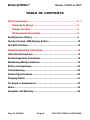
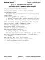
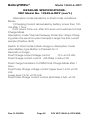
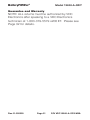
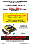
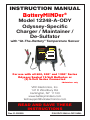
BatteryMINDer©
Model 12248-A-ODY
INSTRUCTION MANUAL
BatteryMINDer®
Model 12248-A-ODY
Odyssey-Specific
Charger / Maintainer /
De-Sulfator
with “At-The-Battery” Temperature Sensor
9LL=JQ'#(=J ¸
Charger / Maintainer /
Full Time De-Sulfator
12-Volt @ 8 Amp
Model 12248-A-ODY
ODYSSEY-SPECIFIC
8A
For Lead-Acid
Batteries ONLY
VDC Electronics, Inc.
800-379-5579 (ET)
www.batteryminders.com
Green = Power ON
ERROR:
Red = Polarity Reversed
/ Battery = less than 3-Volts*
Red (Blinking) = Battery not fully charged charger in float-maintenance mode*
ODYSSEY
BATTERY
ONLY
Battery Condition Indication
Power On & Battery Connected
Before Start Charge:
Green = OK - Accepted
Yellow = Weak / Sulphated / Deep Discharge*
After Charge:
Green = Good
Yellow = Sulphated / Weak*
PRESS
Stop
Restart
Charge - Float
Green (solid) = Charging
Green (blinking) = Float (maintenance)
*See Instruction Manual
Hold for 5 sec. for full reset
For use with all 600, 900* and 1200* Series
Odyssey Sealed 12-Volt Batteries or
(2) 6-Volt Series Connected
*Maintainer only
VDC Electronics, Inc.
147 D Woodbury Rd.
Huntington, NY 11743
www.batteryminders.com
[email protected]
READ AND SAVE THESE
INSTRUCTIONS
Rev. D-050509
D-050509
Page P/NVDC12248-A-ODY-MNL
VDC12248-A-ODY-MNL
P/N
BatteryMINDer©
Model 12248-A-ODY
TABLE OF CONTENTS
Safety Instructions........................................................... 3 - 7
Preparing To Charge...................................................... 5
Charger Location......................................................... 5
DC Connection Precautions............................................. 6
Qualifying Your Battery....................................................... 8
Testing A Sealed, AGM-Odyssey Battery................................... 10
Unit With Call-Outs............................................................ 12
Simplified Operating Instructions........................................... 13
LED Indicator Functions...................................................... 14
Detailed Operation Instructions............................................. 16
Maintaining Multiple Batteries............................................. 22
Battery Configurations........................................................ 23
Troubleshooting................................................................ 24
Detailed Specifications....................................................... 26
Charging Profile............................................................... 31
For Repair or Replacement................................................... 32
Notes............................................................................ 33
Guarantee And Warranty...................................................... 34
Rev. D-050509
Page P/N VDC12248-A-ODY-MNL
BatteryMINDer©
Model 12248-A-ODY
WARNING
Underwriters Laboratories (UL)
REQUIRED SAFETY INSTRUCTIONS
TO REDUCE THE RISK OF FIRE, ELECTRIC
SHOCK, OR INJURY TO PERSON,
OBSERVE THE FOLLOWING:
1. Do not expose charger to rain or snow. It is designed to
operate ONLY INDOORS.
2. USE of any attachment not specifically recommended by
the battery charger manufacturer for use with this exact model
of charger may result in risk of fire & electric shock or injury to
person.
3. An extension cord should not be used, unless absolutely
necessary. Use of an improper extension cord could result in
fire or electric shock. If extension cord must be used be sure:
a. Pins on plug of extension cord are the same number, size, &
shape of plug on charger
b. Extension cord is properly wired and in good condition.
c. Wire size is enough for AC ampere of charger as specified
below: Length of cord, feet (meters) 25 (7.6), 60 (15.2), 100
(30.5), 150 (45.6) AWG Size #18.
4. Do not use charger if it received a sharp blow, been
dropped, or damaged.
5. Charger contains no serviceable parts. If it fails for
any reason, return to the address shown within for a free
replacement under warranty.
6. To reduce risk of electric shock, unplug charger from outlet
before attempting any cleaning.
7. WARNING - RISK OF EXPLOSIVE GASES.
WHENEVER YOU WORK NEAR A LEAD ACID
BATTERY IT IS DANGEROUS. BATTERIES
GENERATE EXPLOSIVE GASES DURING NORMAL
BATTERY OPERATION. FOR THIS REASON,
IT IS OF UTMOST IMPORTANCE THAT EACH
TIME BEFORE USING YOUR CHARGER, YOU
MUST READ THIS MANUAL AND FOLLOW THE
INSTRUCTIONS EXACTLY.
Rev. D-050509
Page P/N VDC12248-A-ODY-MNL
BatteryMINDer©
Model 12248-A-ODY
To reduce risk of battery explosion, follow
these instructions and those published by the
battery manufacturer and the manufacturer of
any equipment you plan to use in the vicinity of
the battery. Review cautionary markings on the
products and the engine.
8. PERSONAL PRECAUTIONS when working with
or near a lead acid battery:
a. Someone should be able to hear your voice or close
enough to aid you when working near a lead acid battery.
b. Have fresh water and soap nearby case battery acid
contact skin, clothing, or eyes. Wear complete eye protection
and clothing protection. Avoid touching eyes while working
near battery.
c. If battery acid does contact skin or clothing, wash
immediately with soap and water. If acid entered the eye,
immediately flood the eye with running water for at least 10
minutes and get help immediately.
d. NEVER smoke or allow a spark of flame near battery or
engine.
e. Be extra cautious to reduce risk of dropping a metal tool
or auto part onto battery. It might spark or short circuit battery
or other electrical part that may cause an explosion.
f. Remove personal metal items such as rings, bracelets,
necklaces, and watches when working with a lead acid
battery. A lead acid battery can produce a short circuit current
high enough to weld a ring or the like to metal, causing a
severe burn.
g. Charger is designed to be used for
recharging lead acid batteries ONLY. Never use it
to power a low voltage electrical system, or for
attempting to recharge dry cell batteries that are
commonly used in house holds. These batteries
may explode and cause injury to persons and
damage property
Rev. D-050509
Page P/N VDC12248-A-ODY-MNL
BatteryMINDer©
Model 12248-A-ODY
NEVER CHARGE A FROZEN BATTERY OR ONE AT
A TEMPERATURE ABOVE 123° F.
PREPARING TO CHARGE
a. If necessary to remove battery from equipment to
charge. Always remove ground terminal first. Turn off all
accessories in the vehicle, so as not to cause an arc.
b. Be sure area around battery is well ventilated while
battery is being charged. Force gas vapors away by using a
piece of non-metallic material as a fan.
c. Clean battery terminals. Be careful to keep corrosion
from contacting eyes.
d. Add distilled water to each cell until battery acid reaches
level specified by the manufacturer. This helps Purge excessive
gas from cells. Do not overfill. For a battery without caps,
follow manufacturer’s recharging instructions.
e. Study all battery manufacturer’s specific instructions
such as removing cell caps while charging and recommended
charge rates.
f. Determine condition of battery, by referring to instructions
herein, before ever attempting to charge or desulphate any / all
batteries.
CHARGER LOCATION
a. Make sure charger is as far away from battery as
output cables permit.
b. Never place charger directly above battery being
charged; gases from battery will corrode and damage charger.
c. Never allow battery acid to drip on charger when reading
specific gravity or filling.
d. Do not operate charger in a closed-in area or restrict
ventilation in any way.
e. Do not set battery on top of charger.
Rev. D-050509
Page P/N VDC12248-A-ODY-MNL
BatteryMINDer©
Model 12248-A-ODY
DC CONNECTION PRECAUTIONS
a. Connect and disconnect DC output clips from battery only
after removing charger power cord from outlet.
b. Attach clips to battery posts and twist or rock back and
forth several times to make good contact. This tends to keep
clips from slipping off terminals and reduces risk of sparking.
FOLLOW THESE INSTRUCTIONS WHEN BATTERY
IS INSTALLED IN EQUIPMENT (VEHICLE, PWC,
BOAT, TRACTOR, ETC.) A SPARK NEAR BATTERY
MAY CAUSE BATTERY TO EXPLODE. TO REDUCE
RISK OF A SPARK NEAR BATTERY:
c. Position DC output cord to reduce risk of damage by hood,
door, covers, or moving engine parts.
d. Stay clear of fan blades, belts, pulleys, and other parts that
can cause injuries.
e. Check polarity of battery posts. POSITIVE (POS, P,+) usually
has a larger diameter than NEGATIVE -.
f. Determine which post of battery is grounded (connected)
to the chassis of equipment. If negative post is grounded see
Item N. If positive post is grounded see item P.
N. For negative grounded equipment, connect POSITIVE
(RED) clip from charger to POSITIVE (POS, P, +) ungrounded
post of battery. Connect NEGATIVE (BLACK) clip to vehicle
chassis or engine block away from battery. Do not connect clip
to carburetor, fuel lines, or metal body parts.
g. For positive ground equipment, connect NEGATIVE
(BLACK) clip from charger to NEGATIVE (NEG, N,)
UNGROUNDED POST OF BATTERY. Connect POSITIVE
(RED) CLIP to chassis or engine block away from battery.
Rev. D-050509
Page P/N VDC12248-A-ODY-MNL
BatteryMINDer©
Model 12248-A-ODY
Do not connect clip to carburetor, fuel lines, or
sheet metal body parts. Connect to heavy gauge
metal part of frame or engine.
h. When disconnecting charger, disconnect charger from
AC outlet, then remove clips from vehicle chassis, and battery
posts.
Operating instructions for charge information.
FOLLOW THESE STEPS WHEN BATTERY IS
OUTSIDE OF VEHICLE OR EQUIPMENT.
A SPARK NEAR THE BATTERY MAY CAUSE
BATTERY EXPLOSION. TO REDUCE RISK OF A
SPARK NEAR BATTERY:
a. Check polarity of battery posts. POSITIVE (POS,P,+)
usually has a large diameter than NEGATIVE (NEG, N, -)
battery post.
b. Connect (RED) charger clip to (POS+) post of battery.
c. Position yourself and free end of cable as far away from
battery as possible, then connect NEGATIVE (BLACK) charger
clip to free end of cable.
d. Do not face battery when making final connections.
e. When disconnecting charger, always do so in reverse
sequence of connecting procedure and break first connection
while as far away from battery as practical.
Do not attempt to permanently install any
charger not specifically designed for permanent
installation, especially in a wet / marine
environment
Rev. D-050509
Page P/N VDC12248-A-ODY-MNL
BatteryMINDer©
Model 12248-A-ODY
QUALIFYING YOUR BATTERY:
Preliminary Requirements
NOTE: The BatteryMINDer has no electrical output unless it
is connected to a healthy battery. Testing the BatteryMINDer
with a volt or an Amp meter without the unit being connected
across a good battery will result in a false reading. If you
experience any problems, or are not sure of how to properly
use or connect your BatteryMINDer, please e-mail our
technical support at: [email protected] or
call our toll-free technical support line 800-379-5579 x206
(Eastern Time). Be certain to leave your phone
number with the area code, time zone and the
best time to call.
To gain the best result from your new charger and to maximize
the life and performance of your batteries we strongly
recommend you qualify (test) your batteries before attempting
to either charge-maintain or desulphate them. Remember,
even if you just purchased a “new” battery it may have been
subjected to conditions that have caused “sulphation” such as
high temperature (>=80°).
NOTE: If your battery is new and you are certain
it was not subject to conditions that could have
caused sulphation*, even before you purchased
it, then you can disregard our recommendations
for qualifying / testing your battery, before using
the BatteryMINDer.
* Such as high temperature storage (=/> 80° F) and/or allowed
to self-discharge to 12.4 Volts or lower.
Testing a Sealed, AGM-ODYSSEY
Lead Acid Battery
USE A DIGITAL VOLTMETER ONLY:
1. Recharge the battery with the BatteryMINDer to ensure it
is as completely charged as possible, before you determine
its condition. Allow battery to “rest” (see pg. 9) overnight for
a minimum of 10 hours before testing with a digital voltmeter
only.
Rev. D-050509
Page P/N VDC12248-A-ODY-MNL
BatteryMINDer©
Model 12248-A-ODY
Failure to test a “rested” (see pg. 9) battery will cause false
readings. Be certain to read and understand all safety related
instructions (pages 3 to 7) before proceeding further.
2. Measure battery’s voltage, without any load attached. If
the voltage is less than 12.4 volts (Typically 50% of charge) the
battery may be too heavily sulphated to be fully recoverable. If
voltage is 12.4-V or higher full recovery can be expected, given
sufficient time (average 1-2 weeks for batteries that are heavily
sulphated).
3. Connect the BatteryMINDer to the battery.
4. Charge battery to its maximum level. Press MaintenanceFloat (select Battery type) button, if it does not go into this
mode automatically. Allow battery to remain for a minimum of
72 hours before retesting. If improvement is seen, continue
until battery voltage reaches full capacity level or no further
increase is seen.
OCV = Open Circuit No Load Voltage
OCV - “Rested Voltage”
Full Capacity Percentage
12.7 Volts
100%
12.5 Volts
75%
12.3 Volts
50%
12.1 Volts
25%
<11 Volts
0%
TABLE 1
Rev. D-050509
Page P/N VDC12248-A-ODY-MNL
BatteryMINDer©
Model 12248-A-ODY
Simplified Operating Instructions
(Read and understand ALL Safety Instructions on
pages (3 -7) and Qualifying Your Battery (pgs. 8
-11) before proceeding)
1. Attach battery connector (either clips or ring terminal
assembly) to output cordset of charger. Use either type,
but not both at same time.
2. Attach charger output to battery’s terminals. RED
sleeve indicator = Positive +, Black = Negative -.
If lit RED, reverse charger connectors on battery
terminals.
Rev. D-050509
Page 10
P/N VDC12248-A-ODY-MNL
BatteryMINDer©
9LL=JQ'#(=J ¸
Charger / Maintainer /
Full Time De-Sulfator
12-Volt @ 8 Amp
Model 12248-A-ODY
For Lead-Acid
Batteries ONLY
VDC Electronics, Inc.
800-379-5579 (ET)
www.batteryminders.com
Green = Power ON
ERROR:
Red = Polarity Reversed
/ Battery = less than 3-Volts*
Red (Blinking) = Battery not fully charged charger in float-maintenance mode*
ODYSSEY-SPECIFIC
8A
Model 12248-A-ODY
ODYSSEY
BATTERY
ONLY
Battery Condition Indication
Power On & Battery Connected
Before Start Charge:
Green = OK - Accepted
Yellow = Weak / Sulphated / Deep Discharge*
After Charge:
Green = Good
Yellow = Sulphated / Weak*
PRESS
Stop
Restart
Rev. D-050509
Page 11
Charge - Float
Green (solid) = Charging
Green (blinking) = Float (maintenance)
*See Instruction Manual
Hold for 5 sec. for full reset
P/N VDC12248-A-ODY-MNL
BatteryMINDer©
Model 12248-A-ODY
LED INDICATOR FUNCTIONS - TABLES 3 (TOP) &4 A&B (BOTTOM)
Battery Condition Indication
Battery connected before charge:Vb<11V YELLOW
Vb<11V GREEN
If pressing Reset Button in the charging
stage
Battery sulphation checked:
STOPS CHARGING AND ALLOWS
RESET OF ALL SELECTIONS
Vb<11V YELLOW
Vb<11V GREEN
Battery sulphation checked: Vb<12.85V* YELLOW
Vb<12.85V* GREEN
*12.85-V for AGM-ODYSSEY battery
POWER /
ERROR
LED Status - (Power / Error and Charge LEDs)
GREEN
A.C. power disconnected, battery connected
correctly
RED
CHARGE
- FLOAT
GREEN
OFF
OFF
A.C. power connected, battery connected
GREEN
OFF
A.C. power connected, battery connected (press
start button)
GREEN
ON
At Soft Start mode, Bulk charge mode,
Absorption mode
GREEN
ON
In Sulphate check mode Float charge mode
GREEN
FLASH
A.C. power connected Reversed Battery Polarity
RED ON
OFF
A.C. power connected, charger output Clip
shorted
RED ON
OFF
A.C. power connected, battery voltage is less
than 3V
RED ON
OFF
Timed-out when in SoftStart or Bulk mode
RED FLASH
OFF
Timed-out when in Absorption mode & Forced
to Float mode
RED FLASH
FLASH
Battery Fault / Battery Weak
RED FLASH
OFF
Rev. D-050509
Page 12
P/N VDC12248-A-ODY-MNL
11
1
7
8
6
5
1) Battery clip cordset w/ qwik connect plug
(pgs.13, 16)
2) Ring terminal cordset w/ qwik connect plug
(pgs. 13, 16)
3) Mounting tabs
4) Input power cordset (pg. 13, 18)
5) Output cord w/ qwik connect plug (pg. 13, 16)
6) Temperature sensor input connector (pg. 17)
7) Charge rate selection button (pgs. 13, 17, 18)
12
2
10
9
8) Battery type selection button (pgs. 13, 17, 18)
9) Start / reset selection button (pgs. 13, 17, 18)
10) LED indicators for power, connection, fault,
battery
condition, charge status (pgs.13-15, 18–20, 24)
11) 12 Volt Power cordset (Optional)
12) Temperature sensor with cord and ring terminal
(pg. 17) (Optional)
4
P/N VDC12248-A-ODY-MNL
Page 13
Rev. D-050509
Model 12248-A-ODY
BatteryMINDer©
BatteryMINDer©
Model 12248-A-ODY
Detailed Operation Instructions
Model 12248
After carefully reading and understanding the Safety
Instructions contained in this manual (pages 3 to 7) and having
evaluated your battery as described in Qualifying Your Battery
(pages 8 to 10) you are properly prepared to begin using your
charger.
1. Attach output cord of charger to either the Battery Clip(s)
Assembly (BCA) (supplied) or the Ring Terminal Assembly
(RTA) (supplied) depending on your preference. However
never use both assemblies at the same time for any reason
whatsoever. Never use either of these assemblies on any other
charger or for any other purpose such as improvised “jumper
cables”, etc. Using the RTA on batteries remaining in their
normal use location (in same place they are regularly installed
will normally prove the safest and most convenient. If you have
several applications you may wish to purchase additional Ring
Terminal Assemblies (RTA) available from your dealer or VDC
Electronics, Inc. directly.
Note: this assembly contains a 15 Amp automotive type fuse
and is replaceable should for any reason it were to blow. Never
replace this fuse with any type whose rating is higher than 15
Amps, as seriously harmful results may occur.
2. Identify the positive and negative posts or connections
on your battery, usually clearly designated with the polarity
markings of + (positive) and – (negative). If you have previously
installed the RTA referred to in 1. above, you need only to
press the connector plug of the charger’s output cord into
Rev. D-050509
Page 14
P/N VDC12248-A-ODY-MNL
BatteryMINDer©
Model 12248-A-ODY
the mating plug of the RTA. Push firmly and do not leave any
space between them. Correct polarity and a good connection
will be your reward. Attach the BCA to the proper battery
posts, clamps or screw terminals, depending on type of
battery. ALWAYS connect the negative (Black)
clip to a metal grounding point (Negative ground
installations such as most modern cars, trucks,
boats, RVs, etc.) as far away from battery as
possible for maximum safety. Never connect to
any type of fuel line.
Note: Older vehicles or other devices may be Positive ground
installations requiring different connection recommendations.
If unfamiliar or unsure which battery type of grounding system
you have, check with our Tech Support personnel before
proceeding further.
Note: Attach temperature compensation Sensor Assembly
(Part# ABS-248), attach the ring terminal of the sensor to the
negative post-connection on the battery and plug the opposite
end into the female receptacle on the charger. This sensor
detects the temperature at the battery when properly installed.
Use of this sensor will increase your battery life significantly,
so please try to use. If you cannot use for your current
application(s), do not discard or misplace.
5. Plug the unit’s Power cord into a standard – grounded 120
Vac electrical outlet. The Power ON LED Indicator will light
GREEN. If it does not light GREEN check the outlet to be
sure it is functioning. In addition, be sure if outlet is controlled
by a switch, no one will accidentally shut off the power to
the outlet. Check for correct polarity = (no ERROR RED
LED Indicator). If ERROR Indicator is lit, reverse the charger’s
Rev. D-050509
Page 15
P/N VDC12248-A-ODY-MNL
BatteryMINDer©
Model 12248-A-ODY
output connections to the battery.
6. The Charge – Float LED Indicator will light GREEN within
15 seconds. The charger will now begin charging by first
checking the battery to determine its voltage and ability to
accept a charge. Should the battery not have a normal fully
discharged voltage (10.5-V minimum) the unit will begin
charging in the “Soft-Start” mode to determine if the battery
can be safely charged. If it cannot, the Power ON – Error LED
will flash RED and charging will be stopped. Battery should
be carefully checked under a load by a qualified person before
further attempting to charge it. Note: If the battery does not
have a minimum no load OCV (Open Circuit Voltage) of 3 volts,
the ERROR LED will light RED and charger will reject battery.
No further effort should be made to charge this battery with
this charger or any charger. Discard this battery, unless it has
just been subjected to a long period of continuous discharge
under a load such as can occur with leaving lights on or
cranking an engine excessively. Allow such a battery to “Rest”
for several hours (overnight if possible) before determining if it
is defective. Be very suspicious of any 12-V battery that does
not have at least 11-Volts (OCV) before it is recharged. It may
well be seriously damaged and unsafe for any type of use or
recharge. The unit’s Battery Condition Indication LED will help
you determine if battery is less than 11-Volts (Yellow)) or
greater than 11-Volts (GREEN)
7. After battery has been fully charged, the GREEN ChargeFloat LED Indicator will begin blinking. It will continue to blink
indefinitely, unless unit is disconnected from battery or Stop
/ Restart button is pressed. Should battery be unable to be
fully charged, the RED Error LED will blink. Battery may not
be able to be fully charged, may be too large or too deeply
discharged to be fully charged in the normal time allowed
by charger. If you are certain battery is not defective, having
read and understood completely all of the above concerns
Rev. D-050509
Page 16
P/N VDC12248-A-ODY-MNL
BatteryMINDer©
Model 12248-A-ODY
and conditions, proceed to restart the charger by pressing
the Stop / Restart button and allow charger to begin charging
battery again. If battery is not defective it should be able to
be fully charged after being restarted. After sufficient time has
lapsed the GREEN charge LED Indicator will blink confirming
when / if battery is now fully charged.
Note: If attempting to charge more than one battery at a
time it is very likely the charger will need to be restarted as
described in order to completely charge multiple batteries. We
do not recommend charging more than one battery at a time
without confirming the individual condition of each battery and
monitoring the charging and batteries closely. A better solution
is to charge each battery separately using model 12248A-ODY. BatteryMINDer and then connect them together, if
desired for long term maintenance-float charging. We suggest
your reading the detailed specifications on pages (26 - 31),
including the additional LED indicator functions (pgs. (14-15)
not already covered above.
After carefully reading these instructions and Troubleshooting
(pgs. 24 - 25) sections should you still have questions, please
e-mail our technical support department at:
[email protected].
Allow up to 3 business days for a detailed response to your
questions. Always identify the model number of the product
and revision letter of this manual contained on this page below.
Without this information we may not be able to assist you
correctly.
If your questions have already been answered in this manual
you can expect a response referring you back to this manual
and the specific page(s).
Note: If your questions relate to safety concerns, please
contact: [email protected] or if a
Rev. D-050509
Page 17
P/N VDC12248-A-ODY-MNL
BatteryMINDer©
Model 12248-A-ODY
potentially hazardous emergency may exist cease using the
product immediately and call (800) 379-5579 Ext 201 (ET)
Monday – Friday or contact our tech support at ext. 206.
Standard operating questions, clearly answered in this manual,
will not be answered by phone.
Rev. D-050509
Page 18
P/N VDC12248-A-ODY-MNL
BatteryMINDer©
Model 12248-A-ODY
MAINTAINING MULTIPLE BATTERIES
BatteryMINDer 12248-A-ODY maintenance charger Desulphators
can be used to maintain up to six (6) 12-volt batteries at a
time, providing each battery is fully operational (no dead-dying
cells), free of sulphate and meeting the minimum full charge
“rested” (see pg. 9) voltage of 2.13 volts / cell, after being fully
desulphated. ALL batteries Must be properly tested to ensure
they are in good condition (no dead-dying cells or excessive
sulphation) before maintaining them in multiples.
Only healthy, fully desulphated batteries should ever be
MAINTAINED in sets of 2 or more. Test sealed batteries using an
accurate, DIGITAL type ONLY, voltmeter. The Minimum voltage
Must not be less than 2.13 volts / cell after fully charging battery
and letting it “rest” for 12 hours minimum, before testing. If battery
voltage is less than 2.13 / cell you must first desulphate it until you
reach a “rested” (see pg. 9) voltage of 2.13 volts / cell.
Remember, you must desulphate each battery by itself (one at a
time) before maintaining them for extended periods. Attempting to
desulphate more than one (1) battery at a time will yield very poor
results, as the strongest (healthiest) and not the weakest (most
sulphated) battery will receive the majority of the desulphation
pulse energy.
Only batteries of the SAME type (engine starting or deep cycle
(but not together), as well as SAME chemistry-construction such
as AGM-ODYSSEY should be maintained together. Never mix
batteries of different type construction / chemistry, or condition
(old with new). ALWAYS test each individual battery to be certain
it is healthy and free of sulphate before attempting to charge
or maintain them, either as a single battery or in sets. NEVER
Rev. D-050509
Page 19
P/N VDC12248-A-ODY-MNL
BatteryMINDer©
Model 12248-A-ODY
connect multiple batteries together for charging purposes using
less than #18 Gauge insulated wire.
VDC Electronics, Inc. does not make nor can it supply or
recommend, any type of wire harness to connect individual
batteries for the purpose of charging them in groups, due
to the many battery terminal sizes and configurations that
exist.
See diagram (adjacent) for the various and most common
multiple battery configurations.
BATTERY CONFIGURATIONS
Model 12248-A-ODY 12 VOLT
12V
TO CHARGER
TO CHARGER
TO CHARGER
TO CHARGER
12V
V
V
12 VOLT
(PARALLEL)
Rev. D-050509
12 VOLT (PARALLEL) Using
6 Volt Batteries
Page 20
P/N VDC12248-A-ODY-MNL
BatteryMINDer©
Model 12248-A-ODY
Troubleshooting - Model 12248-A-ODY
We use the word “Indicator” to mean the various
LEDs (Light Emitting Diodes) showing the various
faults, modes, and conditions of the battery and /
or charger.
The words “unit”, “charger” or “recharger”
means your model 12248-A-ODY BatteryMINDer.
Problem:
Power ON indicator does not light
Solution:
Check electrical outlet. If controlled by a wall switch be sure
switch is on and try to prevent accidental shutting it off while
charger is working.
Problem:
ERROR indicator lights RED
(several possibilities can be the cause)
Solution:
1. Output leads - connections to battery may be reversed.
Switch (reverse) connections at battery
2. If still remains RED check battery voltage. If 3 Volts or less
battery may be damaged and should not be recharged. If
battery was just recently removed from a load (headlights, door
lights, etc. or vehicle not used for extended time without a
charger-maintainer, allow battery to “recover” by letting it “rest”
without a load. If battery is healthy and just deeply discharged
it should recover its voltage (rise above 3 volts) sufficiently
to allow charger to begin an attempt to fully recharge it. If
after battery has “rested” (see pg. 9) it may not be able to
be recovered – recharged. It should be safely discarded
– recycled.
Problem:
ERROR Indicator lights RED and is blinking,
Solution:
1. Battery may be weak or very heavily sulphated. Allow
battery to remain in Maintenance-Float mode for 72 hours
or more and then attempt to recharge again. 2. Battery may
Rev. D-050509
Page 21
P/N VDC12248-A-ODY-MNL
BatteryMINDer©
Model 12248-A-ODY
be so large it may require a second full recharge. Repeat
recharge. 3. If recharging multiple batteries, 2 or more
complete recharge cycles may be needed. Repeat full
recharge. If still RED - blinking, you may need to charge
each battery separately.
Problem:
Battery Condition Indicator lights Yellow (After battery
has been completely charged)
Solution:
Battery still has an unacceptable level of sulphation and must
stay connected to charger and remain in Maintenance-Float
mode (GREEN blinking indicator) for 72 hours or longer. Then
stop charger by pressing STOP/RESTART button and observe
Indicator. If still Yellow repeat (up to 3 full cycles) or until
indicator lights GREEN.
Problem:
Battery Condition Indicator lights Yellow (May be several
causes) (Before battery is completely charged)
Solution.
Battery can be weak due to sulphation, self discharge or was
very deeply discharged. Attempt a full recharge and recheck
after completion. If still Yellow follow procedure for (After
battery has been completely charged.)
Problem.
Charger Indicators show battery is fully charged, but fails to
provide good cranking, lighting or equipment run time, as it did
when newer.
Solution.
Battery may be defective. Have it tested by a qualified source.
Rev. D-050509
Page 22
P/N VDC12248-A-ODY-MNL
BatteryMINDer©
Model 12248-A-ODY
DETAILED SPECIFICATIONS VDC Model No. 12248-A-ODY
8A MCU controlled H.F. Battery Charger
Note: This equipment has been tested and found to comply
with the limits for a Class B digital device, pursuant to part
15 of the FCC Rules. These limits are designed to provide
reasonable protection against harmful interference in a
residential installation. This equipment generates, uses and
can radiate radio frequency energy and, if not installed and
used in accordance with the instructions, may cause harmful
interference to radio communications. However, there is
no guarantee that interference will not occur in a particular
installation. If this equipment does cause harmful interference
to radio or television reception, which can be determined by
turning the equipment off and on, the user is encouraged to
try to correct the interference by one of more of the following
measures:
• Reorient or relocate the receiving antenna.
• Increase the separation between the equipment and
receiver.
• Connect the equipment into an outlet on a circuit different
from that to which the receiver is connected.
Electrical Parameters
Input Voltage:90-140 Vac
Input Frequency: 50/60 Hz
Unloaded input current: 80 mAac
Input Current consumption at 120Vac input, output 13V 8A
loading (UL1236) Approx: 2Aac
Rev. D-050509
Page 23
P/N VDC12248-A-ODY-MNL
BatteryMINDer©
Model 12248-A-ODY
DETAILED SPECIFICATIONS VDC Model No. 12248-A-ODY (con’t.)
Charging Output Control Characteristics
Charging Flow: Battery condition detect>SoftStart
Charge>Bulk Charge
Absorption Charge>Sulphate Check>Float Charge>Float
Pulse Charge
SoftStart Charging Activity conditions:
1) Battery Voltage is over 3 Vdc and less than 10.5 Vdc
2) Press Start Button (If you forget to press Start button
within 10 minutes, charger will automatically start in and remain in 2A current mode & Gel Battery mode)
Soft Start Charging output current control:
(8A Charging Rate) 2.0 Adc ±0.25
Soft Start Charging Time Limit: 6 Hours
Bulk Charging Activity conditions:
1) Battery Voltage is over 10.5 Vdc
Bulk Charging Current control at 8A mode: 8 Adc ±0.45
Max. rated output voltage and current: 13.5V at 8Adc -14.7V at 6.5Adc
Bulk Charging Time Limit: 20 ±1 Hours
Absorption Charge mode Output voltage control
14.7 (AGM-ODYSSEY) @ 24°C ±0.25 VDC
Rev. D-050509
Page 24
P/N VDC12248-A-ODY-MNL
BatteryMINDer©
Model 12248-A-ODY
DETAILED SPECIFICATIONS VDC Model No. 12248-A-ODY (con’t.)
Absorption mode transitions to Float mode conditions:
Mode:
1) Charging Current demanded by battery is less than 100
mA after 1 hour
2) 20 Hours Time-out: after 20 Hours unit switches to Float
Charge Mode
Absorption mode Thermal Runaway Protection: Stops Charging when the second current sample is larger the first current
sample (Positive dI/dt)
Switch to Float mode in Bulk charge or Absorption mode
when Battery type Button is Pressed For 3
Seconds or longer.
Float Charge output Voltage control
13.4 ±0.25 Vdc
Float Charge current control (8A Rate) 4 Adc±0.25
Float charge transitions to PWM Float Charge Mode after 1
Hour
Float Pulse Charge voltage control Upper level 14.0V ±0.25
Vdc
Lower level 13.0V ±0.25 Vdc
Float Pulse Charge current control(8A Rate) 4 Adc ±0.25
Rev. D-050509
Page 25
P/N VDC12248-A-ODY-MNL
BatteryMINDer©
Model 12248-A-ODY
DETAILED SPECIFICATIONS VDC Model No. 12248-A-ODY (con’t.)
Battery sulphation check period (After absorption charge is
finished): 10 minutes
Unloaded output voltage when battery is disconnected: 0.5
Vdc (max.)
Output short-circuit current when battery disconnected:
5mA dc (max.)
Battery flow back current (to the charger) when connected to
12V battery, AC Power disconnected:
30 (max.) mA dc
All LED indicators will shut off if AC power is disconnected for
10 Minutes
Full time Desulphation output pulse current control Ip-p ±3
Adc
Full time Desulphation output PWM* frequency 100 ±10Hz
Full time Desulphtation duty 0.3%
*Pulse Width Modulated
Temperature Compensation (with ABS-248 Battery Temperature Sensor)
Temperature at the Positive Terminal of Battery
Temperature Ranges
Odyssey
Float
>120°F/>49°C
14.1
12.9 ±0.25 Vdc
110-120°F/43-49°C
14.2
13.0 ±0.25 Vdc
100-110°F/38-43°C
14.3
13.1 ±0.25 Vdc
90-100°F/32-38°C
14.4
13.2 ±0.25 Vdc
80-90°F/27-32°C
14.5
13.4 ±0.25 Vdc
70-80°F/21-27°C
14.6
13.5 ±0.25 Vdc
60-70°F/16-21°C
14.8
13.7 ±0.25 Vdc
40-50°F/4-10°C
15.2
14.0 ±0.25 Vdc
>40°F/>4°C
15.4
14.2 ±0.25 Vdc
Rev. D-050509
Page 26
P/N VDC12248-A-ODY-MNL
BatteryMINDer©
Model 12248-A-ODY
DETAILED SPECIFICATIONS VDC Model No. 12248-A-ODY (con’t.)
Transformer
Transformer Type: Ferrite core transformer
Rising Temperature of Transformer: 80º C Max.
Insulation
Primary to Secondary insulation Test:
1240 Vac 60Hz with
1 minutes, 10mA ac no break down found
Primary to core insulation test:
1240 Vac 60Hz with 1 minutes, 10mA ac no break down found
Secondary to core insulation test: 500 Vac 60Hz with 1 minutes, 10mA ac no break down found
Electrical Cable
Input Lead and plug specifications :CUL SJT 18AWG X2 with
UL 2-pin plug, External Length 6 ft
Output lead : 1015 105° C VW-1 16AWG with Trailer connector, External Length 2 ft
Extension cord: 1)1015 105° C VW-1 16AWG with Trailer connector & battery clamp, External Length 2 ft
2)1015 105° C VW-1 16AWG with Ring terminal &
blade type Fuse, External Length 2 ft
Ring terminal I.D dimensions
Negative 8mm, Positive
10mm
Physical Parameters
Weight: 2.2 lbs.
Plastic enclosure material: UL-94V0 #1 Noryl or #2 PC+ABS
#3 PC
Enclosure Dimension:
Approx. 5.713 (W) x 5.516 (L) x
2.86 (H) inches
Environmental Characteristics
Operating temperature : -10° to 40° C
Storage temperature : -10° to 80° C
Operating Humidity range: 0 to 95% RH
Rev. D-050509
Page 27
P/N VDC12248-A-ODY-MNL
14.6-Volt
10.5-Volt
3-Volt
start
Soft Start
(0.5A/1A/2A)
(6 Hours
timer
limited)
Full Time Desulphator
Bulk Charge
(8A 20 Hours timer limited)
Odyssey/AGM Mode:14.6-V @ 24ºC
(with Temperature compensation)
Absorption Charge
AGM Type = Odyssey / AGM
20 hours Max (Time-Out)
Sulphate
Float Charge
Check
(10 min.) (one hour)
Time
Full Time Desulphator
Float-V = 13.7
Float Pulse Charge (PWM)
(1A/2A/4A Max. current Limited)
Time Unlimited
P/N VDC12248-A-ODY-MNL
Page 28
Rev. D-050509
Voltage
Current
Model 12248-A-ODY
BatteryMINDer©
BatteryMINDer©
Model 12248-A-ODY
FOR REPAIR OR REPLACEMENT
In the event that you believe your product may be defective, you MUST speak to a VDC Electronics technician at
1-800-379-5579 x206 (ET) before proceeding further.
If after speaking with our tech support personnel it is
necessary to return the unit, you MUST request an RMA
number.
Items must be returned within 10 days after receiving your
Return Merchandise Authorization number and must be
packed in the original packaging with manual and all connectors included.
Your Return Merchandise Authorization number must be
shown on the return shipping label as follows:
VDC Electronics, Inc.
Returns Department
Attn: RMA # (Enter Your RMA# Here)
147 D Woodbury Rd.
Huntington, NY 11743
All returns must be authorized by
VDC Electronics.
Rev. D-050509
Page 29
P/N VDC12248-A-ODY-MNL
BatteryMINDer©
Model 12248-A-ODY
NOTES:
Rev. D-050509
Page 30
P/N VDC12248-A-ODY-MNL
BatteryMINDer©
Model 12248-A-ODY
Guarantee and Warranty
NOTE: ALL returns must be authorized by VDC
Electronics after speaking to a VDC Electronics
technician at 1-800-379-5579 x206 ET. Please see
Page 32 for details.
Rev. D-050509
Page 31
P/N VDC12248-A-ODY-MNL
BatteryMINDer©
Rev. D-050509
Page 32
Model 12248-A-ODY
P/N VDC12248-A-ODY-MNL