1
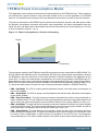
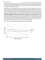
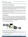
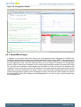
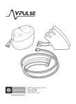
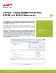
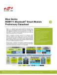
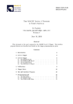
...the world's most energy friendly microcontrollers
Energy Optimization
AN0027 - Application Note
Introduction
This application note is a guide to the most effective ways to reduce energy
consumption in EFM32 applications. By both lowering dynamic and static power
consumption and minimizing the time spent in active modes the overall energy
consumption can be reduced. Hardware and software tools to help identify and
remove energy bugs are also presented.
This application note includes:
• This PDF document
...the world's most energy friendly microcontrollers
1 EFM32 Power Consumption Model
This application note includes several electrical characteristics for the EFM32 devices. These numbers
are included as a typical reference only and could contain errors or not be applicable to all EFM32
devices. It is therefore best to always check the datasheet for the device at hand for precise numbers.
The power consumption of the EFM32 can be split into two main parts, dynamic and static power. While
the dynamic consumption increases with higher clock frequencies, the static consumption stays the
same. As such, the static power consumption can be found by lowering the clock frequency to or close
to 0 Hz as shown in Figure 1.1 (p. 2)
Figure 1.1. Power consumption as a function of frequency
Power
Dynam ic power
Static power
Frequency
The operational modes of the EFM32 are called Energy Modes and are numbered from EM0 to EM4. The
Energy Modes offer different levels of functionality and thus also varying power consumption, allowing
the designer to scale the resources to fit the bare minimum of what is needed in the application at any
given time. To reduce the static power consumption in the lower Energy Modes, the EFM32 has of 3
power domains, where one or two of these domains can be powered down in some of the Energy Modes.
Below is an overview of the main features available in the different Energy Modes, whereas Table 1.1 (p.
3) shows the static power consumed in each of the power domains (based on EFM32TG840F32).
• EM0 - Run Mode: The CPU is running and all peripherals can be used, with power consumption as
low as 150 µA/MHz.
• EM1 - Sleep Mode: The CPU is asleep, but all peripherals can still be used, with power consumption
as low as 45 µA/MHz.
• EM2 - Deep Sleep Mode: The high frequency clocks are switched off and the core power domain is
held in retention mode. The low frequency clocks and peripherals in the low energy power domain can
still be used, with power consumption as low as 900 nA with an RTC running. Wake-up in only 2 µs.
• EM3 - Stop Mode: The high and the low frequency clocks are switched off and the core power domain
is held in retention mode. The asynchronous peripherals in the low energy power domain can still be
used, with power consumption as low as 590 nA. Wake-up in only 2 µs.
• EM4 - Shutoff Mode: The high and the low Frequency clocks as well as the low energy and core
power domains are switched off. The power consumption can be as low as 20 nA, but the device must
be reset to return to EM0 again. In some devices it is possible to run an RTC from a low frequency
clock and keep up to 512 bytes of data retained in this mode as well, then consuming about 400 nA.
2013-09-16 - an0027_Rev1.02
2
www.silabs.com
...the world's most energy friendly microcontrollers
Table 1.1. Energy Modes and powered domains
Power Domain
EM0
EM1
EM2
EM3
EM4
Static power in EFM32TG
(25°C,3V)
Core Domain
On
On
Retained
Retained
Off
~34 µA
Low Energy Domain
On
On
On
On
Off
590 nA
Backup/EM4 Domain
On
On
On
On
On
20 nA
For more information on the Energy Modes in the EFM32 and code examples on how to use them,
please see application note AN0007.
1.1 Running Fast vs. Slow
When processing a task in active mode and tight real-time demands are not in place, one often has
the choice of either lowering or increasing the clock frequency to optimize the energy consumption. By
running from a slower clock, the power consumption decreases while the processing time increases,
and vice versa for higher clock speeds. Both the processing speed of the CPU and the dynamic
power consumption is approximately doubled when doubling the clock frequency. If our static power
consumption was 0 it would not make any difference what frequency we use since a slower clock would
lead to a proportional decrease in power consumption, leaving the consumed energy per computation
the same. However the static power consumption makes the device less effective at lower frequencies.
Hence it is generally most energy efficient to solve tasks in higher energy modes (which means higher
static power consumption) as fast as possible to increase the percentage of time spent in lower energy
modes with lower static power consumption. This is not always true though as in cases where flash waitstates are introduced at higher clock frequencies. Then the processing speed benefit is not linear with
frequency. In such cases it can be the most efficient to run at a frequency just below the wait-state limit
(1 wait state above 16 MHz, 2 wait states above 32 MHz).
To illustrate the benefit of running faster we can look at the typical consumption for the EFM32TG840F32
in EM0 at 14 MHz (calculating prime numbers), which is 155 µA/MHz. On the other hand, if the CPU is
running from the LFXO at 32.768 kHz, the same code will take about 430 times as long to complete.
The power consumption when executing this code when running from the LFXO is about 39 µA, which
is equivalent to an efficiency of almost 1200 µA/MHz and will therefore not be very energy efficient. At
higher frequencies in the MHz range the effect of the static consumption on the per-MHz efficiency is
not as dramatic as in this case, but the same principle still applies.
In some cases the power supply restricts the power consumption to a certain maximum level. In such
cases it is important to use a frequency that is as high as possible within the limits set, to reduce the
energy consumption as much as possible.
2013-09-16 - an0027_Rev1.02
3
www.silabs.com
...the world's most energy friendly microcontrollers
2 Reducing Static Power
This chapter will present some techniques that can be used for reducing the static power consumption
in the EFM32.
2.1 GPIO Leakage
All unconnected pins on the EFM32 should be configured with the GPIO->P[x].MODEL/MODEH settings
to 0 (Disabled). In this setting, both the input schmitt trigger and the output driver are turned off. If the
input is enabled (schmitt trigger enabled), floating inputs could otherwise lead to frequent toggling of
the schmitt trigger and increased power consumption. Out of reset, all GPIO pins are configured as
disabled, except for the debug pins which are enabled with a pull-up (DBG_SWDIO) and a pull-down
(DBG_SWCLK). For pins that are configured with input enabled it is important to make sure that these
pins are driven to a defined high or low voltage by either internal or external pull resistors or strong drive
logic to avoid schmitt trigger toggling in the input logic.
Pins used by analog peripherals (like ADC inputs) should normally be disabled, as enabling the digital
inputs for these pins could cause noise in the measurements originating from the schmitt trigger.
2.2 Disabling RAM Blocks
When the device is in EM2 or EM3, the leakage of the RAM blocks contribute significantly to the
overall power consumption. Some EFM32 devices offer an option to disable some of the RAM blocks
(POWERDOWN bits in EMU_MEMCTRL), which will lower the power consumption. E.g. in a Giant
Gecko device, the current is decreased by approximately 170 nA per 32 KB block that is turned off.
All blocks are automatically enabled when the device is reset. Keep in mind that the linker file used by
the IDE needs to be reconfigured to the smaller RAM size, as normally the full RAM size for the part is
used. Some flash loaders will also have problems programming parts with disabled RAM blocks, so you
should make sure to first erase that flash (erasing the program that turns off the RAM blocks) before
you reset and re-program it using a flash loader.
2.3 Analog Bias Settings
Most of the analog peripherals, like DAC, ACMP etc. include bias current programming settings.
Reducing the bias current to these peripherals will reduce the power consumption, but keep in mind that
the analog performance will also be affected. Some analog peripherals also have the option of reducing
the internal reference power consumption at the cost of accuracy (e.g. LPREF in ACMPn_INPUTSEL).
The analog bias and reference settings only affect the power consumption while the peripheral is enabled
(e.g. EN bit in ACMP_CTRL set). It is important to not that turning off the clock to a peripheral (e.g.
ACMP0 bit in CMU_HFPERCLKEN0) does not reduce the power consumed by the analog part of the
peripheral, but only eliminates the switching activity in the peripheral's digital control logic in EM0 and
EM1.
2.4 Supply Voltage Level
Normally the current consumed by CMOS logic is proportional with the applied voltage. While this is
also true for the EFM32, the logic in these devices are supplied by an internal 1.8 V linear regulator. As
the regulator dissipates the extra power when applying voltages above 1.8 V to the parts, the current
consumption of the EFM32 therefore has very little variation over applied supply voltage. Note also that
the supply voltage applied to the EFM32 power pins should not be as low as 1.8V. For more details, see
the Power Management section in the datasheet for the device.
2013-09-16 - an0027_Rev1.02
4
www.silabs.com
...the world's most energy friendly microcontrollers
3 Reducing Dynamic Power And Energy
In this chapter we will explain the best techniques to lower the dynamic power consumption of the
EFM32. For battery operated applications which run off a limited energy storage, it is really the energy
consumption of an application that is important. To lower energy consumption it is therefore not only
important to limit the power spent at any given time, but it is also vital to reduce the time spent in the
higher energy modes.
3.1 Clock Optimization
When optimizing the energy consumption in your application, the clock setup is often an area where you
can save a lot with some simple steps. This section will present the most effective ways to reduce power
consumption by optimizing the clock setup for your application. In the EFM32, you can choose between
several different oscillators, both fully internal RC oscillators, external sine-wave or square wave clock
generators, or crystal/ceramic oscillators as shown in Table 3.1 (p. 5)
Table 3.1. Main EFM32 clocks
Oscillator
Type
Frequency
Typical
consumption
Typical startup time
Typical use
HFRCO
Internal RC
Run-time selectable: 1,
7, 11, 14, 21 or 28 MHz
22-106 µA
1 µs
Main HF clock
HFXO
External crystal/ceramic
resonator or external
clock
Fixed: 4 -32/48 MHz
for resonators. Less
than 32 or 48 MHz for
external clock.
85-165 µA
400 µs
Main HF clock
AUXHFRCO
Internal RC
Run-time selectable: 1,
7, 11, 14, 21 or 28 MHz
22-106 µA
1 µs
Debug and flash
write timing
LFRCO
Internal RC
Fixed: 32 kHz
190 nA
150 µs
LF peripheral
clock
LFXO
External crystal/ceramic
resonator or external
clock
Fixed: 32.768 kHz
for resonators. Less
than 48 or 32 MHz for
external clock
190 nA
400 ms
LF peripheral
clock
ULFRCO
Internal RC
Fixed: 1 kHz
NA (always on)
NA (always on) Watchdog clock
The EFM32 clock system is split into two parts, the low frequency domain (LF) and the high frequency
domain (HF). Normally, either the HFRCO or the HFXO is selected as the source for all HF clocks,
whereas the LFRCO or the LFXO are selected to run the low frequency peripherals. Only the LFRCO,
LFXO and ULFRCO are available in EM2 and below, hence it is only peripherals that are clocked from
these that can be run in these modes.
3.1.1 Generating Clocks
When selecting an oscillator to use as the HF clock in the EFM32 it is important to choose an oscillator
that is above and as close as possible to the highest frequency used in the application. Further reduction
of the clock frequency for other sub-systems can be done by prescaling the clocks either in the Clock
Management Unit (CMU) or locally in the peripherals. Note that the prescaler logic will consume
additional power compared to using an oscillator that is oscillating directly at the wanted frequency.
Figure 3.1 (p. 6) shows the power consumption when clocking the EFM32TG from an unprescaled
oscillator and the power consumption when running the oscillator at 28 MHz and prescaling to lower
frequencies for the HF clock.
2013-09-16 - an0027_Rev1.02
5
www.silabs.com
...the world's most energy friendly microcontrollers
Figure 3.1. Power consumption penalty when prescaling clocks
The clock system in the EFM32 allows prescaling of the CPU and the peripherals individually allowing
the core and the peripherals to operate at different frequencies. As mentioned in Section 1.1 (p. 3) ,
it is generally best to run the EFM32 at a higher clock frequency in run mode to reduce the energy
consumption when processing in active mode. On the other hand, if the application for instance requires
a serial connection at a given baud rate, then increasing the clock frequency will not make it stay shorter
in the higher energy modes due to the fixed timing of the communication. In this case it is therefore
better to reduce the clock frequency as close to the minimum frequency needed to generate the desired
baud rate. As the two cases above require a different clock settings, it is often a good idea to change
the prescalers and/or oscillator selection on-the-go to ensure the most optimum selection at any time.
In some applications two peripherals might require different clock frequencies. E.g. if a device is clocked
from the 14 MHz HFRCO and TIMER0 requires 14 MHz while TIMER1 only needs 14/16 MHz, then the
local prescaler in TIMER1 can be used to reduce the clock frequency to reduce the power consumed.
If all peripherals (both TIMERs in this case) could operated with a 14/16 MHz clock (but the CPU
needed 14 MHz), it would be most power efficient to prescale the clock to all peripherals using the
CMU_HFPERCLKDIV register rather than using the local TIMER prescalers as this will reduce the clock
frequency at an earlier stage in the clock tree.
Even though the power consumption in EM2 and lower Energy Modes is usually dominated by static
power consumption, power can still be saved by prescaling the RTC, LETIMER and other peripherals
running from the LF clocks. Usually prescaling a 32.768 kHz clock by 32 to 1024 Hz before using it
with these peripherals, gives about 50 nA reduction for each peripheral. Further prescaling is possible,
but will not give noticeable reductions in power and also decrease the timing resolution for the affected
peripherals.
3.1.2 Clock Gating
Automatic clock gating to reduce clocking of unused logic gates is used widely in the EFM32 devices.
While this is for the most part handled automatically by hardware, a peripheral will still consume some
dynamic power if it is clocked even though it is not enabled. E.g. the peripheral needs some logic gates
clocked to decode the activity on the bus to determine if accesses are made to its own memory space.
To totally eliminate clock switching activity in a peripheral in the EFM32, the CMU includes manual
clock gates controlled by the CMU_HFPERCLKEN0,CMU_HFCORECLKEN0, CMU_LFACLKEN0 and
CMU_LFBCLKEN0 registers. By default all peripheral clocks in the EFM32 are switched off, so it is
important to remember to always turn on the clock to a peripheral before configuring it. To save power
it is possible to turn on and off peripheral clocks as they are needed in the application. As the state is
just frozen when the clock is stopped, the peripheral does not need to be re-initialized when the clock
is restored.
2013-09-16 - an0027_Rev1.02
6
www.silabs.com
...the world's most energy friendly microcontrollers
Note that high frequency clocks enabled through the CMU_HFPERCLKEN0 and
CMU_HFCORECLKEN0 registers only consume power when the HF clock is running (i.e. in EM1 and
EM0).
When using peripherals that are clocked from the low frequency oscillators, the LE bit in
CMU_HFCORECLKEN0 must be set. This enables the clock to the synchronizer module between the
LF and HF domains and is needed for bus transactions and interrupt information to cross between the
domains.
3.2 Reducing Active Mode Energy Consumption
This chapter will focus on reducing the energy consumption in run mode by reducing both the CPU
active time and the power consumed.
3.2.1 Compiler Optimization
As a general rule of thumb, higher compiler optimization settings will lead to more energy efficient code.
However whether to optimize for speed or size will depend on the program at hand. While optimizing
for speed will reduce the time in active mode, optimizing for size will reduce the amount of memory
fetches which again reduce the power consumption. Experimenting with these settings could still yield
significant energy savings.
3.2.2 Cache Optimization
Some EFM32s, like the Tiny Geckos and Giant Geckos, include an instruction cache which can store up
to 512 bytes of the last instruction data accessed by the CPU. This enables recently used instructions
to be read in just one cycle and with less energy than a flash read. The cache also helps to save power
by reducing the processing time at higher CPU clock frequencies where instruction fetches from flash
would require wait states.
The cache is by default enabled, but can be disabled and re-enabled by configuring the
MSC_READCTRL register. The instruction cache will only help save energy if the instruction has already
been fetched by the CPU, which is the case if you have loops or function calls in your code that run
the same instructions repeatedly. If your program just runs linearly through the code, then enabling the
cache will actually increase the power consumption slightly, as writing the read instructions to the cache
consumes some power in addition to the flash d accesses.
To help measure the effectiveness of the cache, the cache enabled EFM32s include two performance
counters (MSC_CACHEHITS and MSC_CACHEMISSES) that will increment for evey instruction fetch
that either hits or misses the contents in the cache. The performance counters are started and stopped
by the PCSTART (also resets counters to 0) and PCSTOP bits in MSC_CMD.
Keep in mind that the cache is cleared every time the device wakes up from EM2 or lower energy modes,
so short wake-ups from these modes will not benefit from enabling the cache. More information on the
cache is found in the MSC chapter of the reference manual for the device.
3.2.2.1 Caching Programs Stored in External Memory
The cache is also useful to increase the speed and reduce the energy consumption when executing
programs from an external memory. However, the EFM32 instruction cache only caches instructions
fetched from the Code Space of the memory map (0 - 0x1FFFFFFF). When reading programs stored
in external memories accessed through the regular EBI regions at 0x80000000 and upwards, the
instructions are therefore not cached. To be able to cache instructions from the EBI, the EFM32 includes
an alternative mapping of these regions into the Code Space of the EFM32 starting at 0x12000000.
The CPU can then read and write to any of these regions to access the external memory. Keep in mind
that this alternate mapping is only accessible from the CPU and cannot be used by the regular DMA
or the USB-DMA.
2013-09-16 - an0027_Rev1.02
7
www.silabs.com
...the world's most energy friendly microcontrollers
3.2.3 Replacing Wait Loops With Interrupts
While-loops can be a useful way to halt CPU processing at a certain stage in a program until a certain
condition has been met. The CPU could for instance be waiting for an oscillator to stabilize or for incoming
data on a UART connection. However, a while loop where the CPU continuously checks for a certain
condition is not very power efficient. For this reason the EFM32 has built in a wide range of interrupt
sources that allow the CPU to sleep until a certain condition triggers an interrupt and wakes the device
up. Even in cases where a direct interrupt source is not available for an event, it could still be useful to set
up an RTC to give periodic wake-ups and then put the CPU to sleep for every iteration of the while loop.
3.2.4 Reducing Interrupt Cycles
For applications that cycle between lower energy modes (like EM2) and run mode to only perform
small tasks (like doing an ADC conversion), reducing the cycles spent to handle the interrupts can
give significant energy savings. Normally the Cortex-M3 requires 12 cycles (0 wait-states) to push/pop
variables to/from the stack when both entering and exiting an Interrupt Service Routine (ISR). However,
it is possible to wake-up from an interrupt source without entering an ISR, by using an Wait-For-Event
(WFE) approach, thus saving a significant amount of CPU cycles. As an ISR is not called with this
approach, the program will need to manually figure out which interrupt source was the cause of the
wake-up and the WFE approach is therefore most effective when there are a only small number of wakeup sources in use. The application note AN0039 includes code examples and more information on how
WFE can be used to save interrupt cycles.
3.2.5 DMA Power Savings
Most EFM32s include a DMA Controller that can be used to offload the CPU by handling some of the
memory transfers. In addition to freeing up CPU time, this also allows for energy savings as the CPU can
spend its freed time in sleep. Depending on the SW implementation, a DMA transfer will in many cases
be faster than using the CPU as well, allowing the whole memory transfer to finish faster and more time
to be spent in the lowest Energy Modes. As each initiated DMA transfer has a certain overhead in clock
cycles (fetching descriptor data etc.) the DMA is most efficient when transferring larger blocks of data
in one go, and this is also where the highest energy savings can be achieved. For more information on
ADC operation there are several code examples included in application note AN0013, in addition to the
material in the reference manual for the device.
3.2.6 Peripheral Reflex System
While the DMA helps to offload the CPU by handling memory transfers, the Peripheral Reflex System
(PRS) offloads the CPU by allowing the peripherals to communicate directly with each other instead
such transactions being handled through interrupts. The configurable channel system of the PRS can
for instance be used to transmit trigger signals from a TIMER to an ADC at regular intervals. As these
triggers are sent while the CPU is fully asleep they can allow for significant energy savings in several
applications. The application note AN0025 includes code examples and more information on the PRS
in addition to the material in the reference manual for the device.
3.2.7 Optimization of emlib Functions
The emlib function library for the EFM32 is intended to help designers efficiently and safely bring an
application up and running without having to configure all registers directly. The functions also makes
it easier and safer to port larger parts of code to other projects. As a consequence of this abstraction,
these functions often include more code than what is strictly necessary to achieve the task for a given
application. If extreme speed, code size or energy optimization is needed it could therefore be useful to
extract only the strictly necessary parts of the emlib functions to use in the application code.
3.3 Selection of Energy Mode
In most microcontroller applications, the CPU can spend a large portion of the time asleep. To reduce
the energy consumption it is therefore important to spend this sleep time in the lowest Energy Mode
2013-09-16 - an0027_Rev1.02
8
www.silabs.com
...the world's most energy friendly microcontrollers
allowed by the application. In some cases, peripherals like UARTs etc must still stay awake, which puts
some restrictions which Energy Modes can be used. It is therefore important to check the documentation
for the features and the peripherals needed in the application and select the lowest Energy Mode that
is supported by all units that are needed.
Energy Mode 4 offers the absolute lowest power consumption possible with the EFM32. In this mode,
some devices also have the option of retaining 512 bytes of general purpose RAM memory as well as
keeping the Back-up RTC (BURTC) running. While Energy Mode 4 offers the lowest power consumption,
it does not offer full retention like the other Energy Modes, thus requiring the device to go through a reset
cycle when waking up. This reset cycle requires significantly longer time (see datasheets for details)
than a wake-up from EM2 or EM3. The energy consumed during this reset cycle makes frequent cycling
between EM4 and EM0 inefficient. If the device wakes up frequently, the average current will usually
be lower by using EM2 or EM3 instead as these require less energy for every wake-up. Figure 3.2 (p.
9) shows a comparison of the average current in an application that does periodic wake-up from
EM4 or EM2. As the RAM leakage accounts for a significant part of the current consumption in EM2,
numbers for both Giant Gecko (GG with 128 KB RAM) and Leopard Gecko (LG with 32 KB RAM) are
given. All implementations use the BURTC running from the LFRCO to trigger the wake-up. When the
device wakes up, it toggles a GPIO pin before it goes straight to sleep again.
Figure 3.2. Power consumption for periodic wake-up from EM2 vs EM4
2013-09-16 - an0027_Rev1.02
9
www.silabs.com
...the world's most energy friendly microcontrollers
4 Energy Debugging
Along with the EFM32 parts, Energy Micro also provides a set of tools that designers can use to easily
debug the energy consumption in their application.
4.1 Advanced Energy Monitoring
All starter and development kits for the EFM32 include Advanced Energy Monitoring (AEM). This is a
hardware feature on the kits that measures the current consumption of the VMCU power domain on the
kit. This power domain is separated from the debug part and normally only powers the EFM32. It is also
possible to power other external components from this power domain. The current samples from the
AEM is sent over the J-Link debug connection to a computer.
The AEM is able to measure currents from 0.1 µA to 50 mA with an absolute accuracy of 1µ A and a
relative accuracy of 0.1 µA .The sampling frequency of the regular AEM is 160 Hz, but in some kits (e.g.
EFM32GGSTK3700) this has been increased to 6250 Hz. See the user manual for each kit for more
details on the AEM performance of the specific kit.
As an active debug connection will consume some additional current in the EFM32, it is necessary to
disconnect the debugger and reset the EFM32 before measuring the current consumption to get the
correct current numbers.
4.1.1 AEM Hardware
The EFM32 starter kits include a switch to select which power source to power the EFM32 from.
Figure 4.1 (p. 10) shows the power supply options for the EFM32GG_STK3700. Even though other
power sources can be used, the current consumption can only be measured when powering from the
regulator output from the Debug (DBG) USB. However when powering the EFM32 from other sources it
is still possible to measure the VMCU supply voltage using the AEM. This is useful to monitor the lifetime
of a battery or in energy harvesting applications where the supply voltage indicates how much energy
is left in the storage capacitors. Note that the power supply capabilities vary between the kit types, so
check the user manual for the specific functions of the kit at hand.
5V
USB Mini- B
Connector
Advanced
Energy
Monitor
US
B
D
BG
BA
T
Figure 4.1. EFM32GG_STK3700 AEM Set-up
3.3V
DBG
VMCU
USB
BAT
EFM32
MCU
USB_VREGO
(3.3V)
USB_VREGI
(5V)
USB OTG
Connector
3V Lithium Battery
(CR2032)
4.1.2 Measuring Current of an External Board
As the measured VMCU power supply can also be used to power external components, it is possible to
measure the consumed current in these other boards directly using the AEM as shown in Figure 4.2 (p.
11) . To do this the following must be done:
• Connect the power supply of the external board to the VMCU pins on the EFM32 kit and remember
to also connect the ground pins.
2013-09-16 - an0027_Rev1.02
10
www.silabs.com
...the world's most energy friendly microcontrollers
• Program the EFM32 on the kit to go into Energy Mode 4 (typically 20 nA). Then the current of the
EFM32 on the kit should be well below the accuracy limits of the AEM. To be able to easily gain debug
access to the EFM32 after a reset, it is advised to insert a 3 second delay in your application code
after reset before you enter EM4. The emode example for the kits in Simplicity Studio can be used to
put the device quickly into EM4 without having to write a specific program for it.
• If it is desirable to link the program code running in the EFM32 to the power consumption graph (as
described in Section 4.2.1 (p. 12) ), the SWO output can be enabled. In this case, the SWO pin on
the target board must also be connected to the SWO pin in the debug connector on the EFM32 kit.
Figure 4.2. Using an EFM32 Starter Kit to measure the power consumed by an external board
4.2 energyAware Profiler
The energyAware Profiler (Figure 4.3 (p. 12) ) is a PC tool included in Simplicity Studio that is used to
display the AEM current sample waveform. The current consumption can be found by clicking on specific
points along the graph and it is also possible to calculate the average current over a selected time-span.
This is a very useful tool to get early feedback on how much energy the application is consuming and
to measure the effects of improvement attempts. Remember to disconnect the debugger and reset the
EFM32 to measure more accurately the real application consumption.
2013-09-16 - an0027_Rev1.02
11
www.silabs.com
...the world's most energy friendly microcontrollers
Figure 4.3. energyAware Profiler
4.2.1 Serial Wire Output
In addition to the regular Serial Wire Debug pins for programming and debugging, the EFM32 also
include an optional instrumentation trace feature called Serial Wire Output (SWO). This system allows
the ARM Cortex-M devices to output periodic samples of the Program Counter (PC) or debug statements
from the application code. Once the SWO has been set up to output PC samples, the energyAware
Profiler is able to collect these samples from the kit through the debug interface. By loading the output
file (.out) from the compilation of the program into the Profiler, the tool can link the PC samples to the
compiled C-code for any given point in time. Clicking on the power graph the code window will show the
code that is running at that point in the graph. This is a very useful tool to identify what code is actually
running during periods of higher power consumption. Keep in mind that the SWO sample rate used in
the energyAware Profiler PC sampling is around 2ksamples/s, so it will not give a cycle accurate trace
of the program flow.
2013-09-16 - an0027_Rev1.02
12
www.silabs.com
...the world's most energy friendly microcontrollers
5 Further Reading
For more detailed information on further energy optimization and details on how to implement the
techniques presented in this application notes, the following documents are recommended:
•
•
•
•
•
•
•
•
•
•
Datasheet and reference manual for the part in question
AN0004 Clock Management Unit
AN0007 Energy Modes
AN0012 GPIO
AN0013 Direct Memory Access
AN0016 Oscillator Design Considerations
AN0025 Peripheral Reflex System
AN0039 Interrupt Handling
AN0043 Debug and Trace
WP0002 EFM32 Energy Debugging
When using specific peripherals it is also recommended to go through the specific application notes for
the peripheral as more practical hints and best practice examples can be found there.
2013-09-16 - an0027_Rev1.02
13
www.silabs.com
...the world's most energy friendly microcontrollers
6 Revision History
6.1 Revision 1.02
2013-09-03
New cover layout
6.2 Revision 1.01
2013-05-08
Specified which registers to use to turn off RAM blocks.
Extended description of analog bias settings.
Added peripheral clock prescaling example.
6.3 Revision 1.00
12-02-2013
Initial revision.
2013-09-16 - an0027_Rev1.02
14
www.silabs.com
...the world's most energy friendly microcontrollers
A Disclaimer and Trademarks
A.1 Disclaimer
Silicon Laboratories intends to provide customers with the latest, accurate, and in-depth documentation
of all peripherals and modules available for system and software implementers using or intending to use
the Silicon Laboratories products. Characterization data, available modules and peripherals, memory
sizes and memory addresses refer to each specific device, and "Typical" parameters provided can and
do vary in different applications. Application examples described herein are for illustrative purposes
only. Silicon Laboratories reserves the right to make changes without further notice and limitation to
product information, specifications, and descriptions herein, and does not give warranties as to the
accuracy or completeness of the included information. Silicon Laboratories shall have no liability for
the consequences of use of the information supplied herein. This document does not imply or express
copyright licenses granted hereunder to design or fabricate any integrated circuits. The products must
not be used within any Life Support System without the specific written consent of Silicon Laboratories.
A "Life Support System" is any product or system intended to support or sustain life and/or health, which,
if it fails, can be reasonably expected to result in significant personal injury or death. Silicon Laboratories
products are generally not intended for military applications. Silicon Laboratories products shall under no
circumstances be used in weapons of mass destruction including (but not limited to) nuclear, biological
or chemical weapons, or missiles capable of delivering such weapons.
A.2 Trademark Information
Silicon Laboratories Inc., Silicon Laboratories, the Silicon Labs logo, Energy Micro, EFM, EFM32, EFR,
logo and combinations thereof, and others are the registered trademarks or trademarks of Silicon
Laboratories Inc. ARM, CORTEX, Cortex-M3 and THUMB are trademarks or registered trademarks
of ARM Holdings. Keil is a registered trademark of ARM Limited. All other products or brand names
mentioned herein are trademarks of their respective holders.
2013-09-16 - an0027_Rev1.02
15
www.silabs.com
...the world's most energy friendly microcontrollers
B Contact Information
Silicon Laboratories Inc.
400 West Cesar Chavez
Austin, TX 78701
Please visit the Silicon Labs Technical Support web page:
http://www.silabs.com/support/pages/contacttechnicalsupport.aspx
and register to submit a technical support request.
2013-09-16 - an0027_Rev1.02
16
www.silabs.com
...the world's most energy friendly microcontrollers
Table of Contents
1. EFM32 Power Consumption Model ............................................................................................................... 2
1.1. Running Fast vs. Slow ..................................................................................................................... 3
2. Reducing Static Power ............................................................................................................................... 4
2.1. GPIO Leakage ............................................................................................................................... 4
2.2. Disabling RAM Blocks ..................................................................................................................... 4
2.3. Analog Bias Settings ....................................................................................................................... 4
2.4. Supply Voltage Level ....................................................................................................................... 4
3. Reducing Dynamic Power And Energy .......................................................................................................... 5
3.1. Clock Optimization .......................................................................................................................... 5
3.2. Reducing Active Mode Energy Consumption ........................................................................................ 7
3.3. Selection of Energy Mode ................................................................................................................ 8
4. Energy Debugging ................................................................................................................................... 10
4.1. Advanced Energy Monitoring ........................................................................................................... 10
4.2. energyAware Profiler ..................................................................................................................... 11
5. Further Reading ...................................................................................................................................... 13
6. Revision History ...................................................................................................................................... 14
6.1. Revision 1.02 ............................................................................................................................... 14
6.2. Revision 1.01 ............................................................................................................................... 14
6.3. Revision 1.00 ............................................................................................................................... 14
A. Disclaimer and Trademarks ....................................................................................................................... 15
A.1. Disclaimer ................................................................................................................................... 15
A.2. Trademark Information ................................................................................................................... 15
B. Contact Information ................................................................................................................................. 16
B.1. ................................................................................................................................................. 16
2013-09-16 - an0027_Rev1.02
17
www.silabs.com
...the world's most energy friendly microcontrollers
List of Figures
1.1.
3.1.
3.2.
4.1.
4.2.
4.3.
Power consumption as a function of frequency ............................................................................................. 2
Power consumption penalty when prescaling clocks ...................................................................................... 6
Power consumption for periodic wake-up from EM2 vs EM4 ........................................................................... 9
EFM32GG_STK3700 AEM Set-up ............................................................................................................ 10
Using an EFM32 Starter Kit to measure the power consumed by an external board ............................................ 11
energyAware Profiler ............................................................................................................................. 12
2013-09-16 - an0027_Rev1.02
18
www.silabs.com
...the world's most energy friendly microcontrollers
List of Tables
1.1. Energy Modes and powered domains ......................................................................................................... 3
3.1. Main EFM32 clocks ................................................................................................................................. 5
2013-09-16 - an0027_Rev1.02
19
www.silabs.com