1
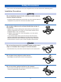
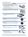
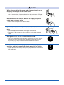
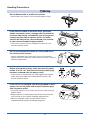
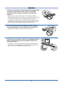
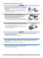
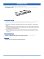
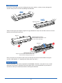
SK 200-09
IMAGE SCANNER
USER’S MANUAL
MANUAL NO. SK200-UM-151
TO ENSURE SAFE AND CORRECT USE
• To ensure the safe and correct use of your Image Scanner, read this manual thoroughly
prior to use.
• After reading this manual, store it in a safe place for reference as necessary.
• Do not allow small children to touch the Image Scanner.
• The following describes important points for safe operation. Be sure to observe them
strictly.
Conventions Used in This Manual
To ensure the safe and correct use of the Image Scanner as well as to prevent human injury
and property damage, the safety precautions provided in this manual are ranked into the
three categories described below. Be sure to gain a full understanding of the difference
between each of the categories before reading the manual.
Danger
This category provides information that, if ignored, is highly likely
to cause fatal or serious injury to the operator.
Warning
This category provides information that, if ignored, is likely to
cause fatal or serious injury to the operator.
Caution
This category provides information that, if ignored, could cause
injury to the operator or physical damage to the Image Scanner.
Description of Safety Symbols
The
symbol indicates information that requires careful attention
(including warnings). The specific point requiring attention is
symbol.
described by an illustration or text within or next to the
The
symbol indicates an action that is prohibited. Such
prohibited action is described by an illustration or text within or next
to the
symbol.
The
symbol indicates an action that must be performed. Such
imperative action is described by an illustration or text within or
next to the
symbol.
i
Safety Precautions
To ensure the safe and correct use of your Image Scanner, be sure to observe the following points.
Installation Precautions
Warning
Do not install the scanner in the vicinity of volatile solvents
such as alcohol or thinner.
• A volatile solvent coming into contact with any of the internal electrical
components may result in a fire hazard or electric shock.
Benzine
Thinner
Do not place objects such as those listed below on top of
the scanner.
• Objects such as these coming into contact with any of the internal
electrical components may result in a fire hazard or electric shock.
♦ Metallic objects such as necklaces
♦ Objects such as glasses, vases, houseplants, etc. that contain
water or other fluids
If any of these objects does come into contact with the internal
electrical components immediately turn off the power, remove the
plug from the power outlet, and either contact the store where you
purchased your scanner or your nearest Graphtec representative.
Caution
Do not use the scanner in an unstable location such as on a
slope or a location that is subject to a lot of vibration.
• Such locations may cause the scanner to tip over and cause injuries.
Do not place heavy objects on the scanner.
• Such objects may tip over or fall off, causing injuries.
Do not use sharp, pointed articles on the scanner.
• Such action may impair the scanner’s performance and cause the
scanner to malfunction or break down.
ii
Do not exert pressure on the scanner.
• Such action may impair the scanner’s performance and cause the
scanner to malfunction or break down.
• Such action could cause injury to the operator.
Avoid installing the scanner in any of the following
locations.
• Use in such locations may result in a fire hazard or electric shock.
♦ Excessively humid or dusty locations
♦ Locations exposed to direct sunlight
♦ Locations exposed to high temperatures
♦ Locations near flames or moisture
Do not install, use, or store the scanner in a location that
does not meet the specified temperature and humidity
ranges.
• Such location may impair the scanner’s performance due to
deformation or damage, and cause the scanner to malfunction or
break down.
Do not install, use, or store the scanner in a location subject
to excessive mechanical vibration or electrical noise.
• Such location may impair the scanner’s performance and cause the
scanner to malfunction or break down.
Leave plenty of space around the scanner.
• Leave sufficient space for operations in front of and behind the
scanner.
When using the scanner on a desktop
At least 300 mm
At least
300 mm
At least
300 mm
At least 200 mm
iii
Power Supply Precautions
Warning
Do not damage the power cable, or modify it in any way.
Moreover, do not place heavy objects on the power cable,
pull on the cable, or bend it excessively.
• There may be current leakage from the damaged parts, resulting in a
fire hazard or electric shock.
• Do not unplug or plug in the power cable when your hands are wet.
Such action may result in electric shock.
Do not connect multiple devices to the same power outlet.
• Use of the scanner in such a condition may result in a fire hazard or
electric shock.
Do not bundle or tie-wrap the power cable.
• Use of a bundled power cable may result in a fire hazard or
electric shock.
Make sure that the power cable is firmly inserted into the
power outlet.
• Use of a power cable when the plug is not completely inserted into
the power outlet may result in a fire hazard or electric shock.
Do not use a power cable other than the one supplied with
your scanner.
• Use of a different power cable may result in a fire hazard or electric
shock.
Do not connect the inkjet printer to a non-rated power
supply.
Spec
ifie
ratin d
g
• Use of a different supply voltage may result in electrical shock or a
fire hazard due to current leakage.
Prohibited
Before disconnecting or reconnecting the power cable, be
sure to turn off the scanner.
• Failure to do so may impair the scanner’s performance and cause the
scanner to malfunction or break down.
• Failure to do so may result in electric shock.
iv
Caution
When disconnecting the power cable, be sure to hold on to
the plug, and not pull on the cable itself.
• Pulling on the cable will expose the core wires, or cause damage
such as broken wires. Current leakage from the exposed or damaged
areas may result in a fire hazard or electric shock.
Before cleaning the scanner, be sure to unplug the power
cable from the power outlet.
• Failure to do so may result in electric shock.
Do not allow dust or metallic matter to adhere to the power
plug.
• If the power plug becomes dirty, thoroughly wipe it clean.
• The use of a dirty power plug may result in a fire hazard or electric
shock.
As a general rule, do not use an extension cord.
• Use of an extension cord may result in a fire hazard or electric shock.
If you must use an extension cord, unbundle it, and make sure that
the power plug is firmly inserted into the extension cord socket.
Make sure that the power plug can be readily unplugged at
any time, and that there are no objects placed in its vicinity.
• Objects placed in the vicinity of the power plug will prevent its removal
in an emergency.
v
Handling Precautions
Warning
Do not disassemble or modify the scanner.
• Such actions may result in a fire hazard or electric shock.
If the scanner makes an unusual noise, generates
smoke, overheats, emits a strange odor, or otherwise
functions abnormally, immediately turn off the power,
remove the plug from the power outlet, and either
contact the store where you purchased your scanner
or your nearest Graphtec representative.
• Use of the scanner in such a condition may result in a fire
hazard or electric shock.
Do not use flammable aerosols or similar products in
the vicinity of the scanner.
• The gas contained in the spray may cause a fire hazard or
electric shock if it comes into contact with the scanner’s internal
electrical components.
Before moving the scanner, make sure that the power
button is in the “off” position and that the power plug
has been removed from the power outlet.
• If the scanner is moved while it is still plugged into the power
outlet, the power cable may be damaged and cause a fire
hazard or electric shock.
If the scanner is damaged from being dropped or other
impact, turn off its power and remove the power plug
from the power outlet.
•Use of the scanner in such status may result in a fire hazard or
electric shock.
•Request repair by contacting the store where you purchased
your scanner or your nearest Graphtec representative.
•Never try to perform repair yourself. Repair work by
inexperienced personnel is extremely dangerous.
vi
Caution
Take care not to drop metallic items such as paper clips
or staples, or spill water, other fluids or flammable
solvents (alcohol, benzene, thinner, etc.) inside the
scanner.
• Metallic items or fluids coming into contact with the internal
electrical components may result in a fire hazard or electric shock.
If such items or fluids fall or are spilled inside the scanner,
immediately turn off the power, remove the power plug from the
power outlet and either contact the store where you purchased
your scanner or your nearest Graphtec representative.
Do not insert your hands inside the scanner during a
scanning operation or when a document is being fed.
• Moving parts inside the scanner may cause injuries.
If the scanner will not be used for an extended length of
time, such as at night, turn off the power button as a
safety precaution.
• In addition, if the scanner will not be used for longer periods of
time, such as a long weekend, remove the power plug from the
power outlet as an additional safety precaution.
vii
Maintenance and Inspection Precautions
Warning
Be sure to turn off the power and remove the power plug
from the power outlet before performing any cleaning
operations.
•Failure to do so may result in a fire hazard or electric shock.
Moreover, there is a risk of injury if the scanner starts to move
during a cleaning operation.
• A volatile solvent coming into contact with any of the internal
electrical components may result in a fire hazard or electric shock.
Neutral
Detergent
To clean the scanner, use a cloth that has been
dampened with neutral detergent and then well wrung
out. Do not use volatile solvents such as alcohol,
benzene or thinner to clean the scanner.
Do not attempt to lubricate the scanner’s mechanisms.
• Such action may impair the scanner’s performance and cause the
scanner to malfunction or break down.
• Such action may cause a fire hazard or electric shock due to a
short circuit or overheating.
Caution
At least once a year, remove the power plug from the power outlet and clean the
prongs and surrounding areas.
• A build-up of dust may result in a fire hazard.
When cleaning or checking the inside of the scanner, make sure that metallic objects
such as a necklace or bracelet do not come into contact with any of the internal
components.
• Such actions may result in injuries or an electric shock.
When removing a document that has become jammed inside the scanner, take care
not to cut your fingers on the edges of the document.
• Such actions may result in injuries.
viii
WARNING
Only computers or peripherals (computer input/output devices, terminals, printers, etc.)
certified as complying with the limits for a Class B digital device, pursuant to Part 15 of
the FCC Rules, may be attached to this product when this product is operated in a
residential environment. Operation with non-certified peripherals is likely to result in
interference to radio and TV.
FEDERAL COMMUNICATIONS COMMISSION RADIO FREQUENCY INTERFERENCE STATEMENT
"This equipment has been tested and found to comply with the limits for a Class B
digital device pursuant to Part 15 of the FCC Rules. These limits are designed to
provide reasonable protection against harmful interference in a residential installation.
This equipment generates, uses, and can radiate radio frequency energy and, if not
installed and used in accordance with the instructions, may cause harmful interference
to radio communications. However, there is no guarantee that interference will not occur
in a particular installation. If this equipment does cause harmful interference to radio or
television reception, which can be determined by turning the equipment off and on, the
user is encouraged to try to correct interference by one or more of the following measures:
• Reorient or relocate the receiving antenna.
• Increase the separation between the equipment and receiver.
• Connect the equipment into an outlet on a circuit different from that to which the
receiver is connected.
• Consult the dealer or an experienced radio/TV technician for help."
ix
INTRODUCTION
Thank you for choosing the Graphtec SK200-09 Image Scanner.
Please read this manual thoroughly before attempting to use your new product to ensure that you
use it safely and correctly.
Notes on this Manual
(1) No part of this publication may be reproduced, stored in a retrieval system, or transmitted, in any
form or by any means, without the prior written permission of Graphtec Corporation.
(2) The product specifications and other information in this manual are subject to change without
notice.
(3) While every effort has been made to provide complete and accurate information, please contact
your nearest Graphtec representative if you find any unclear or erroneous information or wish to
make other comments or suggestions.
(4) Notwithstanding the stipulation in the preceding paragraph, Graphtec Corporation assumes no
liability for damages resulting from either the use of the information contained herein or the use
of the product.
Registered Trademarks
All names of companies, brands, logotypes, and products appearing in this manual are the
trademarks or registered trademarks of their respective companies.
Copyright
This User’s Manual is copyrighted by Graphtec Corporation.
I
Usage precautions
Do not lift or move the scanner by holding the top cover section, as doing so may damage the
scanner. Always lift the scanner by holding the underside.
OK
NG
Top cover section
Take care not to get your fingers caught in the gap between the top cover and the scanner unit when
opening and closing the top cover.
Top cover
<Opening the top cover>
Do not hold the rear section of the
top cover when opening it.
Top cover
<Closing the top cover>
Keep your hands away from the front of the
scanner when closing the top cover.
Always ensure that you open the top cover and remove the cushion material before using the
scanner. (See Section 4.1, “Opening and Closing the Top Cover”.)
Scanner warm-up
A warm-up period is not usually required for the SK200-09. However, if you plan to scan a color
document (in particular a document with many light colors), we recommend that you allow the
scanner to warm up for 10 minutes before scanning the document.
II
CONTENTS
TO ENSURE SAFE AND CORRECT USE ................................................................................... i
Safety Precautions ..................................................................................................................... ii
Installation Precautions .............................................................................................. ii
Power Supply Precautions ........................................................................................ iv
Handling Precautions ................................................................................................. vi
Maintenance and Inspection Precautions .............................................................. viii
INTRODUCTION ........................................................................................................................... I
Notes on this Manual .................................................................................................... I
Registered Trademarks ................................................................................................ I
Copyright ....................................................................................................................... I
Usage precautions ....................................................................................................... II
Scanner warm-up ......................................................................................................... II
CHAPTER 1 BEFORE USING THE SCANNER ..................................... 1-1
1.1
1.2
1.3
1.4
1.5
Checking the Contents of the Package ...................................................................... 1-1
Part Names and Functions .......................................................................................... 1-2
Front View/Control Panel ......................................................................................... 1-2
Rear View ................................................................................................................... 1-3
Assembling the Scanner ............................................................................................. 1-4
Attaching the Rear Guides .......................................................................................... 1-4
Attaching the Anti-curling Guides .............................................................................. 1-5
CHAPTER 2 CONNECTION AND PREPARATIONS .............................. 2-1
2.1
2.2
2.3
2.4
2.5
2.6
Connecting to the Power Supply ................................................................................ 2-1
Turning the Power On and Off .................................................................................... 2-2
Turning the Power On .............................................................................................. 2-2
Turning the Power Off .............................................................................................. 2-2
Notes on the power-saving mode ........................................................................... 2-2
System Requirements ................................................................................................. 2-3
Recommended environment ................................................................................... 2-3
Connecting the Scanner to a Computer .................................................................... 2-4
USB Connection ....................................................................................................... 2-4
Installing the Driver Software ..................................................................................... 2-5
For Windows XP ....................................................................................................... 2-5
For Windows 2000 .................................................................................................... 2-7
Checking the Interface Connection ............................................................................ 2-9
For Windows XP. ....................................................................................................... 2-9
For Windows 2000 .................................................................................................. 2-10
CHAPTER 3 LOADING A DOCUMENT .................................................. 3-1
3.1
3.2
3.3
3.4
3.5
Compatible Document Types ...................................................................................... 3-1
Loading a Document .................................................................................................... 3-2
Handling Documents According to their Material and Thickness ........................... 3-3
Distance Correction ..................................................................................................... 3-3
Using the Carrier Sheet ............................................................................................... 3-4
III
CHAPTER 4 DAILY MAINTENANCE...................................................... 4-1
4.1
4.2
4.3
4.4
4.5
4.6
4.7
Opening and Closing the Top Cover .......................................................................... 4-1
Cleaning the Feed Rollers ........................................................................................... 4-2
Cleaning the Gap Rollers ............................................................................................ 4-3
Cleaning the Image Sensors (Transparent Contact Plates) ..................................... 4-4
Cleaning the Paper Sensors ....................................................................................... 4-5
Removing a Jammed Document ................................................................................. 4-6
Scanner Calibration ..................................................................................................... 4-7
Preparation and checks ........................................................................................... 4-7
Launching the Scanner Adjustment Program ........................................................ 4-7
Calibration ................................................................................................................. 4-8
Color Correction ..................................................................................................... 4-10
CHAPTER 5 TROUBLESHOOTING PROCEDURES............................. 5-1
5.1
5.2
5.3
5.4
5.5
5.6
5.7
5.8
5.9
5.10
5.11
5.12
5.13
5.14
5.15
The scanner Is turned on but doesn’t operate at all ................................................. 5-1
The scanner operates improperly after connection to the computer ..................... 5-1
The control panel’s red ERROR LED is lit ................................................................. 5-1
The control panel’s red ERROR LED is flashing ....................................................... 5-2
The document isn’t properly fed to the initial scanning position ........................... 5-2
The scanned image data is completely white or completely black ......................... 5-2
The image quality has dropped .................................................................................. 5-2
The scanned data is incorrectly aligned .................................................................... 5-3
Smudges not appearing in the original document appear in the scanned data .... 5-3
The color intensity of the image data differs ............................................................. 5-3
The document length differs from the scanned data length .................................... 5-4
Stripes or moire patterns which are not in the original document appear in the
scanned data ............................................................................................................. 5-4
The scanned image data is distorted ......................................................................... 5-4
The scanned image data is patchy ............................................................................. 5-4
The document cannot be fed correctly ...................................................................... 5-4
APPENDIX............................................................................................... A-1
Appendix A Options and Consumables .............................................................................. A-1
Appendix B Specifications ................................................................................................... A-2
Appendix C External Dimensions ........................................................................................ A-3
INDX .......................................................................................................... I-1
IV
CHAPTER 1 BEFORE USING THE SCANNER
1.1 Checking the Contents of the Package
Check to confirm that all of the items shown below are present. If any item is missing, promptly
contact the store where you purchased your scanner or your nearest Graphtec representative.
Scanner unit ...1
USB cable ...1
Anti-curling guides ...1 set
Power cable ...1
Calibration/Color correction sheets ...1 set
Cleaning paper ...1 pack
• One calibration sheet
• One color correction sheet
Rear guides ...1 set
Quick Start Guide ...1
• SK200 Series Quick Start Guide
Software package (CD-ROM) ...1
• Driver software (USB driver/TWAIN driver)
• User’s Manual (PDF format)
• Adobe Acrobat Reader
USB cable
Color correction sheets
USB driver
Power cable
Cleaning paper
TWAIN driver
Anti-curling guides
Software package (CD-ROM)
User’s Manual
1-1
Rear guides
Driver software
Adobe Acrobat Reade
Calibration sheets
Quick Start Guide
1.2 Part Names and Functions
Front View/Control Panel
(2) Paper sensors
(4) Document guides
(1) Top cover
Control Panel
(6) Power button
(7) POWER LED
(8) PAPER LED
(9) ERROR LED
(10) EJECT key
(5) Anti-curling
guides
(11) STOP key
(3) Top cover open levers
Front View
(1) Top cover ....................... Open the top cover to clean the document hold-down unit and
transparent contact plates.
(2) Paper sensors ............... These sense whether a document is present in the scanner.
(3) Top cover open levers ... Press these levers to open the top cover.
If the top cover is opened during a scanning operation, the operation will
be stopped compulsorily.
(4) Document guides .......... Use these guides to determine the position of a document when you
load the document.
(5) Anti-curling guides ........ These guides prevent the document from being caught up in the scanner
during a scanning operation.
Control Panel
(6) Power button ................. Controls the on/off status of the power supply to the scanner.
(7) POWER LED (blue) ...... Unlit: The scanner is turned off.
Lit: Lights when the scanner is turned on and remains lit while it is
operating normally.
Flashing: Flashes when the scanner is in power-saving mode.
(8) PAPER LED (green) ...... Unlit: Normal status (Local status).
Lit: Lights when a document has been loaded.
Flashing: Flashes while image data is being scanned.
(9) ERROR LED (red) ......... Lit: Lights to indicate a hardware error.
Flashing: Flashes when any of the following occurs:
• A document is detected during the self-test when the scanner is turned on
• When a paper jam is detected
• When the top cover is open
• When the document length is shorter than the specified scan length*1
*1 When “Confirm” has been selected for the End-of-paper Processing setting in the driver
software.
Unlit: Normal status
1-2
(10) EJECT key .................. Press this key to feed the document.
If this key is pressed when the scanner is in document-loaded status,
the document-loaded status is canceled and the document is ejected to
the front of the scanner.
If this key is pressed after the scanning operation has been canceled or
after scanning of the document was halted partway through the
scanning operation, the document-loaded status is canceled and the
document is ejected to the rear of the scanner.
(11) STOP key .................... Compulsorily stops scanning of the document.
If the ERROR LED flashes when the top cover is in the closed status,
press this key to suspend the scanning operation and check whether a
paper jam has occurred.
Rear View
(12) Rear guides
(13) USB connector
(14) Power inlet
(12) Rear guides ................. The scanned document is aligned with these guides when it is ejected to
the front.
(13) USB connector ............ Used to connect the USB interface cable.
(14) Power inlet .................. Used to connect the power cable.
1-3
1.3 Assembling the Scanner
Please refer to the separate Stand Assembly Instruction Sheet for the stand assembly procedure.
1.4 Attaching the Rear Guides
Always ensure that the rear guides are attached to the scanner unit before scanning a document,
irrespective of the type of document to be scanned.
Caution
The document may be damaged upon contact with the power cable if it is scanned
without the rear guides in place.
(1) Insert the ribs on the inside of one of the rear guides into the corresponding slots at the
rear of the scanner, and then push the guide downward.
(2) Repeat the procedure for the second guide.
Checkpoint
Detach the rear guides when moving or packing the scanner. Press lightly against
each guide and then lift it up to detach it.
1-4
1.5 Attaching the Anti-curling Guides
Always ensure that the anti-curling guides are attached to the scanner unit before scanning a
document, irrespective of the type of document to be scanned.
Caution
A document that has been returned may get caught up in the scanner and become
damaged if it is re-scanned without the anti-curling guides in place.
Moreover, depending on the condition of the document, there is a risk of it becoming
caught up in the scanner even when the anti-curling guides are used.
If your document falls into one of the following categories, either place the document
inside the carrier sheet that is available as an option, or have the operator manually guide
the returned document so that it does not get caught up in the scanner.
• Curled documents with a width that exceeds A2-size (420 mm)
• Fragile documents with a width that exceeds A2-size (420 mm)
Be sure to use the carrier sheet for documents in the following conditions:
• Considerably damaged documents
• Badly creased documents
(1) Insert the ribs on one of the anti-curling guides into the corresponding slots into the top
cover, and then slide the guide forward.
(2) Repeat the procedure for the second guide.
1-5
CHAPTER 2 CONNECTION AND PREPARATIONS
2.1 Connecting to the Power Supply
Connect one end of the power cable provided to the scanner’s power inlet and the other end to an
AC power outlet of the rated supply voltage.
AC power outlet
Power inlet
Power cable
2-1
2.2 Turning the Power On and Off
The LED (blue) on the [POWER] button changes as follows to indicate the scanner’s power supply
status.
• Unlit: The scanner is turned off.
• Lit: Lights when the scanner is turned on and remains lit while it is operating normally.
• Flashing: Flashes when the scanner is in power-saving mode.
Turning the Power On
Press the [POWER] button on the scanner’s control panel.
When the scanner is in the power-on status, the [POWER] button lights blue.
ON
Turning the Power Off
Press the [POWER] button on the scanner’s control panel.
When the scanner is in the power-off status, the [POWER] button LED is extinguished.
OFF
Checkpoint
After the scanner has been turned off, wait at least five seconds before turning it
on again.
Notes on the power-saving mode
The scanner automatically switches to power-saving mode (the blue LED on the power button
flashes) after approximately 12 minutes have elapsed without a document being loaded in the
scanner. To return the scanner to normal status (Local status), press either the [STOP] or the
[EJECT] key.
To cancel the
power-saving mode
Checkpoint
If a document has been loaded in the scanner, the scanner will not switch to
power-saving mode.
2-2
2.3 System Requirements
The minimum system requirements for running the scanner’s hardware and software are listed
below.
• Operating system: Windows 2000 Professional, XP Professional, or XP Home Edition
• CPU: Pentium III, 1 GHz
• Memory: 256 MB or more
• Monitor: 1024 x 768 pixels, True Color or higher
• Disk space: At least 10 GB*1
• Mouse
• Interface: USB 2.0 interface
*1 When the length of A0 or more is treated, the hard disk space is needed further.
Recommended environment
• CPU: Pentium 4, 2 GHz
• Memory: 1 GB or more
• Disk space: At least 30 GB
• USB 2.0 interface (that comes standard with your computer)
Checkpoint
Use with a system configuration below the recommended specifications will affect
the scanning speed and prevent the scanner from operating to its specified
capabilities. Moreover, colors may not be displayed correctly if the number of
colors that the monitor can display is 256 or less.
To edit an A1-size or larger grayscale document with a resolution of 400 dpi or
higher, or a 24-bit color document, you may need more than the recommended
memory sizes above.
2-3
2.4 Connecting the Scanner to a Computer
USB Connection
A USB cable is used to connect the scanner to the computer, via the respective USB
interface connectors. The connectors at the computer and scanner ends of the USB cable
have different shapes. Make sure that the cable is oriented correctly before making the
connection.
Make sure that both the scanner and the computer are in the power-off status when
connecting them.
USB cable
USB interface connector
Computer
Important
• Make sure that the USB cable is firmly inserted into the interface connectors.
• The operation of the scanner cannot be guaranteed in the following cases:
♦ When the cable is connected to a USB hub or an add-on USB board.
♦ When you are using a custom-built computer or one that you have modified.
• Do not perform any of the following actions:
♦ Remove or reinsert the cable while you are installing the driver.
♦ Remove or reinsert the cable while starting up the computer or the scanner.
♦ Remove or reinsert the cable while transferring data.
♦ Connect two or more scanners to a single computer.
Checkpoint
Please see the separate “Quick Start Guide” for the scanner driver installation
procedure.
2-4
2.5 Installing the Driver Software
Checkpoint
The procedure outlined below is based on the requirement that you are logged on to
Windows with administrator rights. Consult your Windows XP or Windows 2000 manual
for more information.
For Windows XP
(1) Use the USB cable to connect the scanner to the computer, and then turn on the
computer.
(2) When Windows starts up, insert the CD-ROM supplied with the scanner into the CDROM drive. The “Start” screen opens automatically. Click the [Quit] button to close the
“Start” screen.
(3) Turn on the power to the scanner.
(4) When Windows XP starts up, the following screen appears (if Service Pack 2 has not
been installed, the screen shown in (5) below appears). Select the option “No, not this
time” and then click [Next].
(5) If Service Pack 2 has not been installed, the following screen appears. Select the option
“Install from a list or a specific location (Advanced).” and then click [Next].
(6) The screen shown below is displayed. Select the option “Search for the best driver in
these locations” and select the check box entitled “Include this location in the search.”
Click [Browse] and select the [English]-[DRIVER] folders in the CD-ROM drive or enter a
CD-ROM drive name and \English\DRIVER using the keyboard.
Example: For drive D, enter “D:\English\DRIVER”.
2-5
(7) Click [Next]. The wizard will start searching for the driver.
(8) The screen shown below is displayed. Read the explanation and make sure that you
understand the contents.
To continue the installation, click [Continue Anyway].
(9) The screen shown below is displayed when the wizard has finished installing the driver.
Click the [Finish] button to close the “Welcome to the Found New Hardware” wizard.
(10) The Windows XP desktop appears, and the scanner is recognized by the computer.
2-6
For Windows 2000
(1) Use the USB cable to connect the scanner to the computer, and then turn on the
computer.
(2) When Windows starts up, insert the CD-ROM supplied with the scanner into the CDROM drive.
(3) Turn on the power to the scanner.
(4) The screen shown below appears. Click [Next] to move to the “Install Hardware Device
Drivers” screen.
(5) When this screen is displayed, select the option “Search for a suitable driver for my
device (recommended)” and then click [Next] to display the “Locate Driver Files” screen.
(6) When this screen is displayed, select the check box entitled “Specify a location” and click
[Next].
(7) The following screen is displayed. Click [Browse] and select the [English]-[DRIVER]
folders in the CD-ROM drive or enter a CD-ROM drive name and \English\DRIVER using
the keyboard.
Example: For drive D, enter “D:\English\DRIVER”.
Click [OK]. The wizard will start searching for the driver.
2-7
(8) The screen shown below is displayed when the wizard has finished searching. Click
[Next].
(9) The screen shown below is displayed. Read the explanation and make sure that you
understand the contents.
To continue the installation, click [Yes].
(10) The screen shown below is displayed when the wizard has finished installing the driver.
Click the [Finish] button.
(11) The Windows 2000 desktop appears, and the scanner is recognized by the computer.
2-8
2.6 Checking the Interface Connection
For Windows XP.
(1) Launch the Control Panel using the [Start] menu on the Windows desktop.
(2) The screen shown below is displayed when you click on the “Printers and Other
Hardware” icon.
(3) The screen shown below is displayed when you click on the “Scanners and Cameras”
icon.
Check that “Graphtec SK200-09” is displayed here.
2-9
For Windows 2000
(1) Launch the Control Panel using the [Start] menu on the Windows desktop.
(2) The screen shown below is displayed when you click on the “Scanners and Cameras”
icon.
Check that “Graphtec SK200-09” is displayed here.
2-10
CHAPTER 3 LOADING A DOCUMENT
3.1 Compatible Document Types
Because the scanner scans a document while feeding it, the document types that it can scan are
subject to the following restrictions.
Compatible Media Widths for Scanning
Documents with a maximum width of 965 mm
Size
A4
A3
A2
A1
A0
ISO
210 x 297mm
297 x 420mm
420 x 594mm
594 x 841mm
841 x 1189mm
Size
A
B
C
D
E
ANSI
8.5 x 11in
11 x 17in
17 x 22in
22 x 34in
34 x 44in
Note: An A4-size document can only be loaded in Landscape (horizontal) orientation.
Compatible Media Lengths for Scanning
Documents up to approximately 16 m in length can be scanned.
However, the actual document length that can be scanned is limited by the available memory
(hard disk or other data storage device) of the computer to which the scanner is connected,
and also by the grade of the document being scanned.
Compatible Document Thicknesses for Scanning
The SK200-09 cannot scan a document that is thicker than 0.8 mm.
When using the carrier sheet that is available as an option, ensure that the combined
thickness of both the document and carrier sheet does not exceed 0.8 mm.
Moreover, documents of an uneven thickness cannot be scanned.
Note: The carrier sheet alone is 0.2 mm thick.
Compatible Media Grades and Thicknesses for Scanning
Media Grades
• The scanning precision is guaranteed for the special chart (Mylar) used in the test (see
APPENDIX B, “SPECIFICATIONS”).
• The compatible media types are listed below.
♦ High-grade paper: 60 g/m2
♦ Tracing paper: 50 to 55 g/m2
♦ Mylar: 50 µm
♦ Copy paper
♦ Diazo photo-sensitive paper
Be sure to use the carrier sheet that is available as an option when scanning a document
where the ink or toner comes off when it is rubbed. If the carrier sheet is not used, there is a
risk of the document feed path becoming stained, and causing subsequent documents to
become stained as well.
3-1
3.2 Loading a Document
How to use the document guides
Insert the document (the surface to be scanned) face up into the scanner until the top edge
of the document contacts the feed rollers. At this time, make sure that the document is
straight and that it is centered in the scanner.
(1) With the top cover in the closed status, turn on the scanner’s power supply.
(2) Move the document guides to the left and right until they are adjusted to the document width.
(3) Place the document between the document guides, and then insert the document into the
gap between the top cover and the document-scanning table, making sure that it is straight.
(4) When the preset delay time specified in the driver software has elapsed, the rollers start
turning to automatically feed the document to the position to start scanning. The
document is now loaded.
(5) After the document has been loaded, move the document guides back to the position
where the Document edge dotted lines can be seen. If the guides are not moved, the
document may get damaged if it is fed at an angle.
Document guides
Top cover
Document-scanning table
n
ectio
s dir
thi
ert in
Ins
Document to be scanned
If you want to reload the document, press the [EJECT] key to eject the
document. Reload the ejected document.
When the document has been loaded, the [PAPER] LED (green) lights.
Checkpoint
Caution
If the PAPER LED does not light after the document feed operation has stopped,
press the EJECT key to eject the document.
• If the document is inserted at an angle, the image may be scanned in at an angle
or a scanning error may occur. Make sure that the document is aligned with the
document guides when it is inserted.
• When the scanner has been turned on, the automatic feed operation starts after
the specified interval of approximately three seconds has elapsed.
• Load the document in the scanner with the surface to be scanned face up.
• Do not place anything other than the document to be scanned on the documentscanning table. If you do so, the scanner rollers may start rotating, which is
extremely dangerous.
• The document may not be fed in correctly if it is curled. The carrier sheet that is
available as an option should be used for curled documents (see Section 3.5,
“Using the Carrier Sheet” for details).
• Load the document in the center of the scanner, as the document may be fed in
at an angle and not scanned correctly if it is significantly off-center.
• Load the document in the center of the scanner. If it is significantly off-center, the
document may shift and may not be scanned correctly.
3-2
3.3 Handling Documents According to their Material and Thickness
The following problems may occur, depending on the thickness and surface condition of the
document being scanned.
• The document cannot be loaded.
• Scanning of the document stops half-way through.
• The document slips (resulting in displaced images).
• The end of the document is not scanned.
Such problems may be avoided by taking the following corrective measures.
• Lower the scanning speed.
• Support the document at the front and the back of the scanner.
3.4 Distance Correction
Corrections to the distance can be achieved using the driver software. The “Adjust” button on the
TWAIN driver’s “Settings” tab can be used to perform distance correction and adjust the scanning
precision.
The adjustment function must be performed when a scanned drawing needs to approximate the
accuracy of the original drawing closely. (This is for making fine adjustments to the accuracy of the
scanned drawing to suit the quality of the paper being used.) It is not normally necessary to perform
this adjustment.
Adjustment method
Perform the distance correction process according to the type of document to be scanned.
Distance correction can be set in a range of ±1%, which remains effective until the scanner’s
power is turned off. The practice of distance correction necessitates that you measure a
vertical line drawn on the document before following the procedure described below.
(1) Choose a document that has one or more vertical lines drawn on it and scan it at a
resolution of 600 dpi in Portrait (vertical) orientation.
(2) Use a ruler or similar implement to measure the length of the selected vertical line in the
document and classify it as “x” (distance on the document).
(3) Load the saved file into an application capable of measuring and calculating the line
length in the image.
(4) Measure the length of the same line in the image data, and call it value “y” (Distance
Measured After Scanning).
(5) Click on the [Distance Correction] button in the [Adjust] screen to open the [Distance
Correction] screen.
(6) Enter the value “x” (distance on the document) and the value “y” (distance after the scan
has taken place) in this screen The values entered here must be within the distance
correction range (±1%).
(7) Click the [OK] button to calculate the correction value. The distance will be corrected the
next time a document is scanned.
3-3
3.5 Using the Carrier Sheet
Use the carrier sheet according to the condition of the document to be scanned.
In the case of scanning the following types of media, always place the document in the carrier sheet
that is available as an option before loading it into the scanner.
• To scan a document that is smaller than A4 size or a document of non-standard size
• To scan a document that is as limp as or limper than a newspaper
• To scan a document that tears or becomes damaged easily
• To scan a document that is considerably damaged
• To scan a document that is badly creased
• To scan a curled document
• To scan a transparent or translucent document
• To scan a document to which other pieces of paper have been attached
• When the target document cannot be properly advanced to the initial position of scanning
(because the target document is not flat, or otherwise hard to load in the scanner)
• Curled documents with a width that exceeds A2-size (420 mm)
• Fragile documents with a width that exceeds A2-size (420 mm)
As shown in the figure below, place the document in the carrier sheet with the document’s
surface to be scanned face up (against the transparent top sheet). For scanning, load the
carrier sheet into the scanner with the document’s target surface (the transparent top sheet)
face up.
Transparent sheet (top surface)
on
recti
is di
th
ert in
Ins
White surface
(background surface)
Checkpoint
Target document
(the surface to be scanned faces up)
• The carrier sheet is an option.
• When handling the carrier sheet, be very careful not to scratch or otherwise
damage it.
• If you use the carrier sheet when scanning color documents, the colors may shift
slightly in some cases.
3-4
CHAPTER 4 DAILY MAINTENANCE
4.1 Opening and Closing the Top Cover
Opening the top cover
(1) Turn off the scanner.
(2) Push the left and right open levers on the top cover in the upward direction to unlock
them, and then open the cover fully (approximately 60 degrees).
(3) When the cover is fully open, lower it slightly to engage the top cover fixing stay that
holds the top cover in place.
2
1
Closing the top cover
(1) Raise the top cover slightly from its open status to disengage the top cover fixing stay,
and then close the cover gently.
(2) Check that the left and right levers on the top cover are locked.
2
1
Caution Take care not to get your fingers caught when opening or closing the cover.
4-1
4.2 Cleaning the Feed Rollers
(1) Turn off the scanner.
(2) Open the top cover as described in Section 4.1, “Opening and Closing the Top Cover”.
(3) While rotating the feed rollers, wipe them clean using a soft cloth that has been
moistened with water or a neutral detergent (diluted with water) and firmly wrung out.
Feed rollers
(4) Wipe the feed rollers once again using a soft, dry cloth to remove all the moisture.
(5) Close the top cover as described in Section 4.1, “Opening and Closing the Top Cover”.
Caution
• Take care not to get your fingers caught in the top cover.
• Scanning may be affected if the document hold-down unit becomes scratched or
dirty.
4-2
4.3 Cleaning the Gap Rollers
(1) Turn off the scanner.
(2) Open the top cover as described in Section 4.1, “Opening and Closing the Top Cover”.
(3) While rotating the gap rollers, wipe them clean using a soft cloth that has been
moistened with water or a neutral detergent (diluted with water) and firmly wrung out.
Gap rollers
(4) Wipe the gap rollers once again using a soft, dry cloth to remove all the moisture.
(5) Close the top cover as described in Section 4.1, “Opening and Closing the Top Cover”.
Caution • Take care not to get your fingers caught in the top cover.
• Scanning may be affected if the document hold-down unit becomes scratched or
dirty.
4-3
4.4 Cleaning the Image Sensors (Transparent Contact Plates)
The scanner’s image quality drops when the transparent contact plates over the image sensors
become dirty, so clean the image sensors whenever necessary.
(1) Turn off the scanner.
(2) Open the top cover as described in Section 4.1, “Opening and Closing the Top Cover”.
(3) As shown below, wipe off any soiled areas on the transparent contact plates using a soft
cloth that has been moistened with water or a neutral detergent (diluted with water) and
firmly wrung out.
Transparent contact plates
(4) Wipe the transparent contact plates once again using a soft, dry cloth to remove all the
moisture.
(5) Close the top cover as described in Section 4.1, “Opening and Closing the Top Cover”.
Caution
• Take care not to get your fingers caught in the cover.
• Do not use a commercial cleaner for office equipment, a glass cleaner, or
chemical solvents such as solutions containing alcohol. Moreover, although the
transparent contact plate is not a maintenance part that requires periodic
replacement, it is a consumable part because its surface may receive slight
scratches due to minute particles of dust and other foreign matter. If document
scanning produces unsatisfactory results (unexpected white or black streaks in
the data) due to scratches on the transparent contact plate or other reasons,
please perform the calibration procedure (see Section 4.7, “Scanner
Calibration”). If the scanning results do not improve after calibration, the
transparent contact plate(s) will need to be replaced.
4-4
4.5 Cleaning the Paper Sensors
Accumulated dust on the paper sensors may prevent the document from being detected. The
sensors must be cleaned when necessary.
(1) Turn off the scanner.
(2) Open the top cover as described in Section 4.1, “Opening and Closing the Top Cover”.
(3) Wipe the paper sensors (at the front and rear) using a cotton swab.
Paper sensors
(4) Close the top cover as described in Section 4.1 “Opening and Closing the Top Cover”.
Caution
• Take care not to get your fingers caught in the top cover.
• Use a cotton swab or something equally soft to gently wipe the paper sensors.
Do not use any chemicals to clean the sensors.
4-5
4.6 Removing a Jammed Document
If a document becomes jammed in the scanner during scanning or another operation, follow the
procedure described below to remove the jammed document.
(1) Turn off the scanner.
(2) Open the top cover as described in Section 4.1 “Opening and Closing the Top Cover”.
(3) If the document is jammed at the front, remove the document by pulling it forward.
(4) If the document is jammed at the rear, remove the document by pulling it out along the
rear guides.
Rear guides
(5) Close the top cover as described in Section 4.1, “Opening and Closing the Top Cover”.
Caution • Take care not to get your fingers caught in the top cover.
• When removing a jammed document, pull on it gently to prevent damage to the
document.
4-6
4.7 Scanner Calibration
Calibrate the scanner if scanning quality is observed to deteriorate, with scanned results such as
those described below
• The scanned image is distorted
• Areas of uneven color appear in the scanned image
• Other unsatisfactory results (but excluding problems related to media quality, such as folds,
creases, or paper curl)
Preparation and checks
Recommended usage environment
Monitor: 1024 x 768 pixels, High Color or better resolution
Checkpoint
A low-resolution monitor will make it difficult to discern any problem areas.
Launching the Scanner Adjustment Program
(1) Connect the scanner to the computer, switch on the scanner, and then switch on the
computer.
(2) Install the TWAIN driver if it is not already installed.
(3) Select “Adjust” > “Scanner Adjustment” from the TWAIN driver’s “Settings” tab.
(4) Click Scanner Adjustment to launch the Scanner Adjustment program.
(5) Select the desired adjustment item from the Scanner menu.
4-7
Calibration
Before beginning calibration, clean the transparent contact plates located inside the scanner
and the surface of the document-scanning table. Any dust or dirt on these surfaces may affect
the calibration results and the resulting image quality.
Check that the calibration sheet is free of any dust or dirt.
Caution
Checkpoint
• The calibration procedure will take some time. Do not turn off the scanner while
calibration is underway. Accidentally turning off the scanner may result in
damage that requires servicing.
• Handle the calibration sheet with care so that it does not get bent. To prevent
soiling, store it in its special storage box.
• The calibration sheet is a consumable item. It cannot be used if it is bent or soiled.
• The calibration sheet is a paper product. Do not attempt to clean it with any type
of liquid cleaner.
A prompt instructing you to insert the calibration sheet in the scanner will be
displayed in Step 3. At that time, insert the calibration sheet as instructed, with the
notch at the bottom left, as shown in the diagram below.
Scanner
Insertion direction
Calibration sheet
Notch
(1) Launch the Scanner Adjustment program (as described earlier), and then display the
Scanner menu.
Select Calibration on the Scanner menu.
(2) Select All in Calibration and click the [Execute] button.
(3) The following prompt is displayed. Insert the calibration sheet into the scanner as instructed.
(4) Click the [OK] button to begin calibration.
4-8
(5) Calibration ends after approximately 10 minutes.
Click the [OK] button to complete calibration.
(6) To check the calibration results, click the [Confirm] button in the Calibration screen
(shown in step (2) above).
(7) The following prompt is displayed. Insert the calibration sheet into the scanner once
again as instructed.
(8) Click the [OK] button to start scanning.
The scanned data is displayed when scanning is complete. Colors may differ slightly for
individual sensors to make it easier to identify problem areas in calibration. This does not
indicate a defect.
Check that there are no vertical streaks, such as white patches, in the scanned data.
(Streaks occur when calibration is not performed correctly due to contamination by dust
or dirt.)
(9) If the data is normal, calibration is complete. Click the [Close] button and exit the Scanner
Adjustment Program.
(10) If any abnormal data is observed, specify the problem areas as follows:
Select Calibration from the Scanner menu, and then select Specified Part in the
Calibration screen.
(11) The mouse arrow cursor changes to a cross cursor when moved over the data. Click the
left mouse button with the mouse positioned over the streak data. The selected area is
shown in blue. Repeat this procedure for any additional streaks.
Areas that have been selected (shown in blue) can be deselected by clicking the left
mouse button again. To deselect all selected areas, click the [Clear] button.
(12) Once all the required areas have been specified, remove the calibration sheet and clean
the transparent contact plate and document-scanning table surfaces. Check the
calibration sheet for dust and dirt.
(13) Click the [Execute] button and then follow the instructions displayed on the screen. The
procedure will be the same as that described in Steps (3) to (5) above. (The time
required for calibration will vary according to the number of repeats specified.)
(14) Perform Steps (8) to (10) once more, and verify the calibration results.
Caution
If you perform the calibration procedure several times with no discernible results,
there may be a problem with the scanner itself. In this case, please contact the
store where you purchased your scanner or your nearest Graphtec representative.
4-9
Color Correction
Perform color correction if there is any discrepancy in color in parts of the scanned image
even after you have calibrated the scanner.
Caution
• Handle the color correction sheet with care so that it is does not get soiled, bent
or scratched. A soiled, bent, or scratched sheet will not give good results.
• The color correction sheet is a consumable item. It cannot be used if it is bent or
soiled.
• The color correction sheet is a paper product. Do not attempt to clean it with any
type of liquid cleaner.
Color correction sheet
Scanner
Insertion direction
(1) Display the Scanner menu.
Select Color Correction.
(2) The following screen is displayed. Click the [Scan] button.
(3) The following prompt is displayed. Insert the color correction sheet into the scanner as
instructed.
Checkpoint
Position the color correction sheet so that the red bar in the center of the
sheet is centered in the scanner.
(4) Click the [OK] button to start scanning.
The scanned data is displayed when scanning is complete. Colors may differ slightly for
individual sensors, but this does not indicate a defect.
4-10
(5) When the data is displayed, click the [Get] button.
(6) Click in the center of the color tiles indicated by the numbers 1 to 6 on the color
correction sheet, in ascending order. For numbers 1 to 5, click in the center of the upper
left tile; for number 6, click in the center of the bottom right tile. Align the cursor
crosshairs with the printed reference lines beside each of the indicated tiles.
Cursor lines (red)
Align with the printed lines then click
1
2
3
4
5
6
Caution
• The next reference point to be checked is displayed on the Status bar.
• If you click in error, click the [Esc.] key to cancel the operation and return to
the immediately previous step.
• If you click on the wrong tile, color correction will not be performed correctly
and the colors of the image displayed after color correction will be incorrect.
(7) Click the [Set] button to perform color correction.
(8) When color correction has been completed, click the [OK] button.
(9) To check the color correction results, select Color Correction from the Scanner menu,
and then click the [Confirm] button in the Color Correction screen.
4-11
(10) The following prompt is displayed. Insert the color correction sheet into the scanner as
instructed.
Checkpoint
Position the color correction sheet so that the red bar in the center of the
sheet is centered in the scanner.
(11) Click the [OK] button to start scanning.
After scanning has been completed, an enlarged view of the color-corrected data is
displayed.
(12) Click the Fit icon to display the entire image, and check whether there is any discrepancy
in color. If there is no discrepancy, color correction is complete. Click the [Close] button.
Checkpoint
If there is still some color discrepancy after performing Color Correction:
• Repeat the Color Correction procedure.
• Perform the Calibration procedure, and then repeat the Color Correction
procedure.
If you perform the color correction procedure several times with no discernible
results, there may be a problem with the scanner itself. In this case, please contact
the store where you purchased your scanner or your nearest Graphtec
representative.
4-12
CHAPTER 5 TROUBLESHOOTING PROCEDURES
If the scanner seems to be operating abnormally, perform the troubleshooting procedures described
in this chapter before requesting a service call.
5.1 The scanner Is turned on but doesn’t operate at all
Cause
The power cable has come loose.
The scanner is connected to a power outlet
that does not provide the rated power supply or
supply voltage.
The power outlet is not supplying a supply
voltage.
Remedy
Insert the power plug firmly.
Use only the rated power supply and supply voltage.
Check the power supply.
5.2 The scanner operates improperly after connection to the computer
Cause
Is the scanner properly grounded?
Is the USB cable between the computer and
the scanner working properly?
Is the USB cable compliant with the USB 2.0
interface that you are using?
Is an add-on USB card being used?
Remedy
Make sure that the scanner is grounded.
Determine whether there are any problems with either of the
cable connectors (e.g. a broken or bent pin) and ensure that
the cable is inserted firmly into the connectors.
Ensure that you use a USB 2.0-compliant USB cable.
USB 1.1 add-on cards are not supported. Correct operation is
not guaranteed when the scanner is connected to a USB port
that is not the standard built-in computer port.
5.3 The control panel’s red ERROR LED is lit
Cause
A ROM, RAM or other hardware error occurred
during the scanner’s self-test.
Remedy
An internal error has occurred. Contact the store where you
purchased your scanner or your nearest Graphtec
representative.
5-1
5.4 The control panel’s red ERROR LED is flashing
Cause
The scanner was turned on with a document
left loaded inside it.
The top cover was opened during a scanning
operation or while a document was left in the
scanner.
If the document is jammed…
The length of the actual document is longer
than the document length setting made in the
Scanning Arts SP driver.
The top cover is not fully locked.
Remedy
Open the cover and remove the document (see Section 4.6,
“Removing a Jammed Document”).
Press the control panel’s [STOP] button to cancel the error
state. Next, remove the document by pressing the [EJECT]
button to feed the document.
Open the cover and remove the document (see Section 4.6,
“Removing a Jammed Document).”
The scanner’s ERROR LED flashes when the end of the
document is reached, but this does not indicate a problem
with the scanner itself. Follow the instructions provided by the
driver.
Close the top cover firmly until it is locked in place (see
Section 4.1, “Opening and Closing the Top Cover”).
5.5 The document isn’t properly fed to the initial scanning position
Cause
The document is curled, too thin, or otherwise
in a poor condition.
Dust has accumulated on the paper sensors.
The document to be scanned may be too thick
or heavy.
The document is a thick, long-length
document.
Remedy
Load the document after placing it inside the carrier sheet
that is available as an option (see Section 3.6, “Using the
Carrier Sheet”).
Clean the paper sensors (see Section 4.5, “Cleaning the
Paper Sensors”).
In such cases, you should support the document with your
hands when you insert it into the scanner, lower the scanning
speed specified in the TWAIN driver, or both.
Load the document while supporting it with your hands.
5.6 The scanned image data is completely white or completely black
Cause
The document was loaded with its target
surface face down instead of up.
The scanning conditions set were
inappropriate for the document.
Remedy
Load the document in the scanner with its target surface (the
surface to be scanned) face up.
Set the scanning conditions again (they can be controlled
from the TWAIN driver provided with your scanner).
5.7 The image quality has dropped
Cause
The transparent contact plates over the image
sensors are dirty.
l The document is transparent or translucent,
but a carrier sheet was not used.
Remedy
Clean the transparent contact plates (see Section 4.4,
“Cleaning the Image Sensors”).
l Use the carrier sheet that is available as an option.
5-2
5.8 The scanned data is incorrectly aligned
Cause
The data is misaligned at a joint between the
image sensors (see the figure below).
Checkpoint
Your scanner comes shipped from the factory after being adjusted to ensure high
precision.
Due to its operating environment or other factors, however, the scanning precision may
deviate in very rare cases. Moreover, fine adjustment to correct any deviation can be
performed using the driver software if the cause of the deviation is overlapped or missing
data. Deviations due to the scanner specifications, however, cannot be adjusted.
Overlapped data
Original
document
Remedy
Select “Adjust” > the “Scanner Adjustment” menu from the
TWAIN driver’s “Settings” tab to perform joint adjustment and
align the joints.
Missing data
Data is
overlapped
Deviation due to scanner specifications
Original
document
Data is
missing
Joint between
sensors 1 and 2
Original
document
Deviation caused
by the specifications
Joint between
sensors 3 and 4
Joint between
sensors 2 and 3
Joint between
sensors 4 and 5
Sensor 2
Sensor 4
Image sensor position
Control panel side
Sensor 1
Markings on the
document-scanning table
Sensor 3
A2
8.5
Sensor 5
8.5
A2
Document feed direction
Caution
Because the document is loaded face up, Sensor 1 is the leftmost sensor in the driver
software’s display screens.
5.9 Smudges not appearing in the original document appear in the scanned data
Cause
The image scanned has a glossy surface, such
as a photograph.
Remedy
Documents with a glossy surface should be scanned by
placing them inside the carrier sheet that is available as an
option.
5.10 The color intensity of the image data differs
Cause
The scanner contains five contact image
sensors, the characteristics of which have
been adjusted. However, some variation in
color intensity may occur, depending on the
type of document scanned.
The document scanned was creased or curled.
Remedy
Adjust the color using the color-correction function in the
driver software provided with your scanner. One adjustment
method is to make similar colors all the same color.
l Creased or curled documents should be scanned by placing
them inside the carrier sheet that is available as an option.
5-3
5.11 The document length differs from the scanned data length
Cause
Distance correction adjustments have been
made to ensure scanning precision for a
document of a different paper type. The
scanning precision varies according to the type
of document.
Remedy
Select “Adjust” > the “Scanner Adjustment” menu from the
TWAIN driver’s “Settings” tab to perform distance correction
and adjust the scanning precision.
5.12 Stripes or moire patterns which are not in the original document appear in the scanned data
Cause
The scanned document contains filled or
shaded areas.
Remedy
Depending on the resolution selected, data that is comprised
of filled or shaded areas may be scanned in as stripes or
moiré patterns. This is not due to a scanner malfunction.
Note, however, that the vividness of the stripe and moiré
patterns can be lessened by changing the resolution.
5.13 The scanned image data is distorted
Cause
The scanner’s image scanning quality has
deteriorated.
Is the scanner properly grounded?
Remedy
Perform calibration (see Section 4.7, “Scanner Calibration”).
Make sure that the scanner is grounded.n.
5.14 The scanned image data is patchy
Cause
The scanner’s image scanning quality has
deteriorated.
You are using a carrier sheet with a color
document.
Remedy
Perform calibration (see Section 4.7, “Scanner Calibration”).
Don’t use the carrier sheet that is available as an option with
color documents.
5.15 The document cannot be fed correctly
Cause
The document is fed at an irregular rate
(resulting in the images being scanned
unevenly) or stops feeding half-way through.
The document has been loaded at an angle.
Remedy
The cause of this problem is often attributable to the weight
or length of the document. In such cases, you should support
the document with your hands when you insert it into the
scanner, lower the scanning speed specified in the TWAIN
driver, or both.
Reload the document.
5-4
APPENDIX
Appendix A Options and Consumables
Optional and consumable items can be obtained from the store where you purchased your scanner
or your nearest Graphtec representative.
Options
Part no.
ST0064
Item name
High stand
Consumables
Part no.
IS0907
IS0908
IS0917
EM-CP
Item name
Carrier sheet (A0)
Carrier sheet (A1)
Calibration sheet
Cleaning paper (50 sheets)
A-1
Appendix B Specifications
Item
Document size
Effective scanning area
Guaranteed scanning precision range*3
Document thickness
Optical resolution
Interpolated resolution
Main scanning system
Sub scanning system
Scanning speed*4
Scanning precision*3
Gradation
Monochrome
Grayscale
Color
Threshold value
Color space
Sensor
Total number of pixels
Output
Light source
Interface
Output
Rated power supply
Operating environment
Power consumption
External dimensions (approx.)
Weight
SK200-09
ANSI E to ISO A4
Maximum width: 965 mm; minimum width: 257 mm*1
Width: 932.2 mm (centered)
Length: 16 m*2
841 x 1189 mm
Up to 0.8 mm (including the carrier sheet)
600 dpi
100, 200, 300, 400, 600, 800, 1200 dpi
Contact image system (five A4 sensors in a zigzag pattern)
Document travel (sheet through) system
400 dpi, ISO A0 size
High-speed scan
Normal scan
High quality scan
• Monochrome: 8 s
• Monochrome: 14 s
• Monochrome: 18 s
• Grayscale: 23 s
• Grayscale: 26 s
• Grayscale: 33 s
• 24-bit color: 62 s
• 24-bit color: 75 s
• 24-bit color: 100 s
±0.1% or ±1 pixel, whichever is larger
Bilevel, intermediate tones (dithering, error diffusion)
256 shades
24-bit
A DSP (digital signal processor) enables automatic setting of the
threshold value (monochrome scans only)
sRGB-compatible
22,020 pixels
Color: 42 bits/pixel, Grayscale: 14 bits/pixel
LED (RGB)
USB 2.0
Image data
100 to 120/200 to 230 VAC ±10%, 50/60 Hz
Temperature: 10˚C to 35˚C
Humidity: 35% to 80% RH (non-condensing)
60 W or less (12 W or less in power-saving mode*5)
1097 (W) x 160 (H) x 322 (D) mm
Approx. 24 kg
*1 Load A4-size documents in the Landscape (horizontal) orientation.
*2 If the document is a long-length document, the actual length that can be scanned is limited by the available memory (hard disk
or other data storage device) of the computer to which the scanner is connected, and also by the grade of the medium being
scanned.
*3 Notes on scanning precision
The scanning precision may vary slightly depending on the grade and thickness of the medium being scanned, and on the
operating conditions. The precision figures above were measured under the operating conditions described below.
• Special test chart: Mylar sheet #300
• Guaranteed precision conditions: Temperature: 23˚C ± 5˚C; Humidity: 55% ± 15% RH
*4 Including data-transfer time
The following system was used to measure the scanning speeds.
• CPU: Pentium 4, 3.2 GHz or better
• Memory: 1 GB or more
• Interface: USB 2.0
The scanning speeds may be slower depending on the PC system used.
*5 Only when the power supply is 100 to 120 VAC.
A-2
Appendix C External Dimensions
160
Unit: mm
Dimensional accuracy: ±5 mm
1070
322
1097
A-3
1100
When the scanner is mounted on the high stand
720
1185
A-4
INDX
A
I
Adobe Acrobat Reade ................................. 1-1
Anti-curling guides ............................... 1-1, 1-2
Anti-curling guides, Attaching ...................... 1-5
Image sensors, Cleaning ............................ 4-4
Interface connection, Checking ................... 2-9
INTRODUCTION ............................................. I
B
J
BEFORE USING THE SCANNER .............. 1-1
Jammed document, Removing ................... 4-6
C
L
Calibration ................................................... 4-8
Calibration sheets ....................................... 1-1
Carrier sheet, Using .................................... 3-4
Cleaning paper ............................................ 1-1
Color correction ......................................... 4-10
Color correction sheets ............................... 1-1
Compatible document types ........................ 3-1
CONNECTION ............................................ 2-1
Consumables .............................................. A-1
Contents of the Package ............................. 1-1
Control panel ............................................... 1-2
Copyright ......................................................... I
LOADING A DOCUMENT ........................... 3-1
N
Notes on this manual ...................................... I
O
Options ........................................................A-1
P
PAPER LED ................................................ 1-2
Paper sensors ............................................. 1-2
Paper sensors, Cleaning ............................. 4-5
Part names and functions ........................... 1-2
Power button ............................................... 1-2
Power cable ................................................ 1-1
Power inlet .................................................. 1-3
POWER LED ............................................... 1-2
Power On and Off ....................................... 2-2
Power supply, Connecting ........................... 2-1
Power-saving mode .................................... 2-2
PREPARATIONS ........................................ 2-1
D
DAILY MAINTENANCE ............................... 4-1
Distance correction ..................................... 3-3
Document guides ................................ 1-2, 3-2
Document, Loading ..................................... 3-2
Driver software ............................................ 1-1
Driver software, Installing ............................ 2-5
E
Q
EJECT key .................................................. 1-3
ERROR LED ............................................... 1-2
External Dimensions ................................... A-3
Quick Start Guide ........................................ 1-1
R
F
Rear guides ......................................... 1-1, 1-3
Rear guides, Attaching ................................ 1-4
Rear view .................................................... 1-3
Recommended environment ....................... 2-3
Registered trademarks .................................... I
Feed rollers, Cleaning ................................. 4-2
Front view .................................................... 1-2
G
Gap rollers, Cleaning .................................. 4-3
S
H
Scanner adjustment program ...................... 4-7
Scanner calibration ..................................... 4-7
Scanner to a computer, Connecting ............ 2-4
Scanner, Assembling ................................... 1-4
Handling documents according ................... 3-3
I-1
Software package (CD-ROM) ..................... 1-1
Specifications .............................................. A-2
STOP key .................................................... 1-3
System requirements .................................. 2-3
T
Top cover ..................................................... 1-2
Top cover open levers ................................. 1-2
Top cover, Opening and Closing ................. 4-1
Transparent contact plates .......................... 4-4
TROUBLESHOOTING PROCEDURES ...... 5-1
TWAIN driver ............................................... 1-1
U
Usage precautions ......................................... II
USB cable ................................................... 1-1
USB connection .......................................... 2-4
USB connector ............................................ 1-3
USB driver ................................................... 1-1
User's Manual ............................................. 1-1
W
Warm-up ........................................................ II
I-2
The specifications, etc., in this manual are
subject to change without notice.
SK200-UM-151
December 19, 2006
3rd edition-01
GRAPHTEC CORPORATION
503-10 Shinano-cho, Totsuka-ku,
Yokohama 244-8503, Japan
Tel : +81(045) 825-6250
Fax : +81(045) 825-6396
Email : [email protected]
Web : www.graphteccorp.com
Printed in Japan