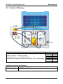
1
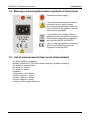
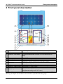
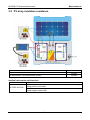
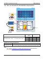
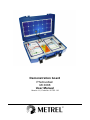
Demonstration board Photovoltaic MI 3088 User Manual Version 1.0, Code No. 20 752 118 Distributor: Manufacturer: METREL d.d. Ljubljanska cesta 77 1354 Horjul Slovenia web site: http://www.metrel.si e-mail: [email protected] Mark on your equipment certifies that this equipment meets the requirements of the EU (European Union) regulations concerning safety and electromagnetic compatibility. © 2013 METREL No part of this publication may be reproduced or utilized in any form or by any means without permission in writing from METREL. 2 1 Introduction .................................................................................................................. 4 1.1 General Description ................................................................................................ 4 1.2 General warnings ................................................................................................... 4 1.3 Applied standards ................................................................................................... 5 1.4 Meaning of warning/information symbols on front panel ......................................... 6 1.5 List of measurements that can be demonstrated .................................................... 6 2 Front panel description ............................................................................................... 7 3 Measurements .............................................................................................................. 8 3.1 Continuity of earthing system.................................................................................. 8 3.2 PV array insulation resistance ................................................................................ 9 3.3 Measurement of irradiation and temperature ........................................................ 10 3.4 Uoc, Isc test and I/V characteristic measurement ................................................. 11 3.5 Automatic test sequence ...................................................................................... 12 3.6 PV panel test ........................................................................................................ 13 3.7 Measurement of inverter input – DC side .............................................................. 14 3.8 Measurement of inverter output – AC side ............................................................ 15 3.9 Inverter efficiency ................................................................................................. 16 4 Technical data ............................................................................................................ 17 5 Maintenance ............................................................................................................... 18 5.1 Cleaning ............................................................................................................... 18 5.2 Service ................................................................................................................. 18 6 Standard set ............................................................................................................... 19 3 MI 3088 PV demonstration board Introduction 1 Introduction 1.1 General Description PV demonstration board simulates photovoltaic electricity generation system. The PV demonstration board is preferably intended for sales persons to demonstrate operation and application of PV test equipment. However, it could also be applied as training and educational tool. Various tests supported by different PV test instruments can be presented. It is placed into a practical plastic carrying case. Demonstration/simulation possibilities: - PV array d.c. output, - Measurement of d.c. current, - Inverter operation with measurement of a.c. output current and voltage, - Pyranometer simulation, - Temperature simulation - Insulation resistance of PV array, - Continuity of protective earthing. Demonstration board is designed according to European safety standard EN 61010-1. 1.2 General warnings • • • • • • If the equipment is not used in a manner specified by manufacturer, the protection provided by equipment may be impaired. Use the PV demonstration board on well-grounded supply systems only. Only qualified personnel, familiar with the board and the measuring instrument may use the PV demonstration board! Application of the PV demonstration board in a way not specified in this User Manual could damage the board. Do not use PV demonstration board in case of any damage noticed! Only an authorized person may carry out servicing of PV demonstration board! 4 MI 3088 PV demonstration board Introduction 1.3 Applied standards The PV demonstration board MI 3088 is manufactured and tested in accordance with the following regulations: Electromagnetic compatibility (EMC) EN 61326 Electrical equipment for measurement, control and laboratory use – EMC requirements Class B (Hand-held equipment used in controlled EM environments) Safety (LVD) EN 61010-1 Safety requirements for electrical equipment for measurement, control and laboratory use – Part 1: General requirements Functionality Reference standard for photovoltaic systems Grid connected photovoltaic systems – Minimum requirements for EN 62446 system documentation, commissioning tests and inspection Note about EN and IEC standards: Text of this manual contains references to European standards. All standards of EN 6XXXX (e.g. EN 61010) series are equivalent to IEC standards with the same number (e.g. IEC 61010) and differ only in amended parts required by European harmonization procedure. 5 MI 3088 PV demonstration board Introduction 1.4 Meaning of warning/information symbols on front panel Indication of power supply. Take care that demonstration board is connected only to mains voltage according to the description under the mains socket! In the opposite case the board can be damaged! The product must undergo selective disposal for the recycling of the electric and electronic material in compliance with directive WEEE 2002/96/EC. The CE marking guarantees conformity with European directives and with regulations covering EMC. 1.5 List of measurements that can be demonstrated - PV string insulation resistance, Bonding resistance of PV panel metallic support to protective earthing, PV string U/I characteristics, PV string d.c. current, PV string d.c. power, Irradiance, Temperature on PV panels, Inverter output a.c. current, Inverter output a.c. voltage, Inverter output a.c. power, Inverter and PV system efficiency. 6 MI 3088 PV demonstration board Front panel description 2 Front panel description 1 2 3 4 Front panel Case PE connection Inverter d.c. input voltage 5 6 7 8 9 10 11 12 13 14 Inverter d.c. input current Pyranomter output PV array output Connection to metallic construction Case cover with label Temperature probe output Inverter a.c. output voltage Inverter a.c. output current Supply indicator Supply entry 15 Warning symbol Presents typical components required in PV power utility. Plastic case of PV demonstration board with handle. For testing purposes only! Sockets for measurement of inverter d.c. input voltage (from PV array). For applying d.c. current clamps. Output for demonstration of irradiance measurement. Output representing PV array I/U characteristics. Intended for continuity measurement of grounding system. Label representing PV panel. Output representing PV array temperature. Sockets for measurement of inverter output a.c. voltage. For applying a.c. current clamps. Indicates proper supply of the PV demonstration board. IEC appliance coupler for supplying the PV demonstration board, universal power supply input 115 V / 230 V To pay attention for right connection to proper mains power supply. Warning: All outputs are intended for demonstration of possible PV testing only! 7 MI 3088 PV demonstration board Measurements 3 Measurements 3.1 Continuity of earthing system Measurement location Connection to metallic construction – PE connection Nominal value 0.1 Ω Applied instruments and functions Instruments Functions R LOWΩ; 200 mA resistance measurement (INSTALLATION menu) MI 3108 R LOWΩ; 200 mA resistance measurement (SOLAR menu) MI 3109 8 MI 3088 PV demonstration board Measurements 3.2 PV array insulation resistance Measurement location PE connection – DC switch board + socket PE connection – DC switch board - socket Nominal value 96 MΩ 92 MΩ Applied instruments and functions Instruments Functions RISO +; Insulation resistance measurement between panel / array / string positive and earth MI 3108, MI 3109 RISO -; Insulation resistance measurement between panel / array / string negative and earth 9 MI 3088 PV demonstration board Measurements 3.3 Measurement of irradiation and temperature Pyranometer Measurement location Pyranometer sockets Nominal value 780 W/m2 Temperature Measurement location Temperature probe connector * Depends on real ambient temperature and internal heating. Nominal value 25 °C * Applied instruments and functions Instruments Functions ENV.: MEAS; Measurement of environmental parameters MI 3108, MI 3109 (Irradiance, temperature) 10 MI 3088 PV demonstration board Measurements 3.4 Uoc, Isc test and I/V characteristic measurement Measurement location Measured value DC switch board + socket – DC switch board - socket Isc Uoc Umpp Impp Pmpp 48.2 3.1 44.8V 2.4 A 107 W STC value Isc Uoc Umpp Impp Pmpp 49 4.1 45.2 V 3.1 A 140 W Applied instruments and functions Instruments Functions Uoc/Isc; Open circuit voltage and short circuit current measurement, MI 3108, MI 3109 I/V; current/voltage and current/power characteristics measurement Note: STC values are displayed if irradiance and temperature are measured before. See chapter 3.3 Measurement of irradiation and temperature. 11 MI 3088 PV demonstration board 3.5 Measurements Automatic test sequence Measurement location PE connection – DC switch board + socket – DC switch board - socket Measured STC value value 96 MΩ 92 MΩ 48.2 49 V 3.1 4.1 A Applied instruments and functions Instruments Functions AUTOTEST; Automatic measurement of insulation resistance and MI 3109 Uoc/Isc of PV panel / array / string. Notes: Applicable only on MI 3109. STC values are displayed if irradiance and temperature are measured before. See chapter 3.3 Measurement of irradiation and temperature. 12 MI 3088 PV demonstration board Measurements 3.6 PV panel test Measurement location Measured value DC switch board + socket – DC switch board - socket Umpp Impp Pmpp STC value 48.2 V Umpp 3.1 A Impp 151 W Pmpp 48.5 V 4.1 A 200 W Applied instruments and functions Instruments Functions PANEL; Current, voltage inverter working point MI 3108, MI 3109 Note: STC values are displayed if irradiance and temperature are measured before. See chapter 3.3 Measurement of irradiation and temperature. 13 MI 3088 PV demonstration board Measurements 3.7 Measurement of inverter input – DC side Measurement location Inverter input + socket – Inverter input – socket Embraced red current loop using A 1391 current clamp Measured value UDC 48.2 V IDC 3.1 A PDC 151 W Applied instruments and functions Instruments Functions INVERTER: DC; Measurements at DC side of inverter MI 3108, MI 3109 14 MI 3088 PV demonstration board Measurements 3.8 Measurement of inverter output – AC side Measurement location AC switch board L – AC switch board N Embraced black current loop using A 1391 current clamp Nominal value UAC 227 V IAC 0.60 A PAC 135 W Applied instruments and functions Instruments Functions INVERTER: AC; Measurements at AC side of inverter MI 3108, MI 3109 15 MI 3088 PV demonstration board Measurements 3.9 Inverter efficiency Measurement location Inverter + socket – Inverter - socket AC switch board L – AC switch board N Embraced red and black current loops using A 1391 current clamps Nominal value UDC 48.2 V IDC 3.1 A PDC 151 W UAC 227 V IAC 0.60 A PAC 135 W η 90 % Applied instruments and functions Instruments Functions INVERTER: AC/DC; Measurement of efficiency of inverter MI 3108, MI 3109 16 MI 3088 PV demonstration board Technical data 4 Technical data Nominal mains voltage .............................. 115 V/ 230 V, 50 Hz / 60 Hz Power consumption ................................... 200 W Mains cord………………………………….. single-phase Dimensions (width × length × height) ......... 450 × 330 × 110 mm Weight ....................................................... 4.47 kg Protection class ......................................... I (protective earth conductor) Over voltage category ............................... CAT II 300 V Pollution degree ........................................ 2 Reference conditions Reference temperature range.................... 10 °C ÷ 30 °C Reference humidity range ......................... 40 %RH ÷ 70 %RH Operation conditions Working temperature range…………………0 °C ÷ 40 °C Maximum relative humidity ........................ 95 %RH (0 °C ÷ 40 °C), non-condensing Storage conditions Temperature range………………..…………-10 °C ÷ 70 °C Maximum relative humidity ........................ 90 %RH (-10 °C ÷ 40 °C), 80 %RH (40 °C ÷ 70 °C), 17 MI 3088 PV demonstration board Maintenance 5 Maintenance 5.1 Cleaning Use a soft cloth slightly moistened with soapy water or alcohol to clean the surface of the board and then leave the board to dry totally before use. Do not use liquids based on petrol! Do not spill liquids over the board! 5.2 Service In case of unusual response of Demonstration board or if there is any damage noticed, the product has to be taken to an authorized service. Consult the producer or your dealer for further information. The product has no internal user serviceable parts (fuses, etc). Producer's address: METREL d.d. Ljubljanska 77 1354 Horjul Slovenia Tel.: +386 (0)1 7558 200 Fax.: +386 (0)1 7549 095 or +386 (0)1 7549 226 18 MI 3088 PV demonstration board Standard set 6 Standard set Upon receipt of Demonstration board it is advisable to check the content of the delivery. The following items have to be included: • • • • • • Demonstration board Mains cable PS2 male / male adapter Test lead 1.5 m, black Test lead 1.5 m, red User manual 19 MI 3088 PV demonstration board Standard set 20