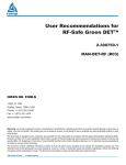
1
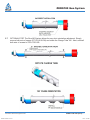
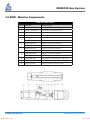
3-1/8” ZERO180™ Gun System
Assembly and Arming Procedures
MAN-Z180-000 (R01)
Please check Owen website at
www.corelab.com/owen/ to confirm latest revision of User Manual
12001 Cr 1000
Godley, Texas, 76044, USA
Phone: +1 (817) 551-0540
Fax: +1 (817) 551-1674
www.corelab.com/owen
Warning: use of owen equipment contrary to manufacturer’s specifications or operating instructions may result in property damage, serious injury or
fatality. If you are not trained in the handling and use of explosive devices, do not attempt to use or assemble any owen perforating systems or owen
firing devices.
This technology is regulated by and, if exported, was exported from the united states in accordance with the export administration regulations (EAR).
Diversion contrary to U.S. Law is prohibited. Export and/or re-export of this technology may require issuance of a license by the bureau of industry and
security (BIS), U.S. Department of Commerce. Consult the BIS, the EAR, and/or Owen Compliance Services, Inc. To determine licensing requirements
for export or re-export of this technology.
This document contains confidential information of Owen Oil Tools LP (Owen) and is furnished to the customer for information purposes only. This
document must not be reproduced in any way whatsoever, in part or in whole, or distributed outside the customer organization, without first obtaining
the express written authorization of owen. This document is the property of owen and returnable upon request of Owen.
© 2015 Owen Oil Tools
MAN-Z180-000 3.125.indd 1
All rights reserved
11/3/15 9:24 AM
ZERO180 Gun System
Table Of Contents
1.0 BOM and Schematic .......................................................................................4
2.0Pre-Assembly...................................................................................................5
3.0 BOM - Wireline Components...........................................................................8
Wireline Electrical Contact Kit (ZRO-3125-000)..............................................9
4.0 Wireline Loading Procedures.........................................................................10
5.0 Wireline Arming Procedures..........................................................................17
6.0 BOM - TCP Components...............................................................................20
7.0 TCP Loading Procedures...............................................................................21
2 I MAN-Z180-000-(R01)
MAN-Z180-000 3.125.indd 2
© 2015 Owen Oil Tools All rights reserved
11/3/15 9:24 AM
ZERO180 Gun System
DESCRIPTION
The Owen Oil Tools Zero180 gun system provides the latest technology in
oriented perforating. Designed for horizontal wells, the Zero180 system lowers
completion costs and increases production results. The new generation wireline
version of the Zero180 offers a patent pending electrical contact design which
allows the system to rotate freely without wearing or damaging electrical
connections. The shaped charges are oriented with an eccentrically weighted
charge tube assembly. This patent pending weight system provides high torque
to ensure accuracy of rotation and shot placement. The Zero180 system is
compatible with Tubing Conveyed Perforating (TCP), Coiled Tubing, or Wireline
with conventional select fire systems.
KEY FEATURES AND BENEFITS
• Orientation accuracy +/- 8%
• Uniform hole size & accurate shot placement
• Reduces break-down and treating pressures
• Simple and quick gun assembly
• Electrical contacts reduce connections and ensure free rotation
• Charge tube rotates within gun carrier - not affected by well bore debris
• No additional downhole equipment
• Quick adjustable orientation
SPECIFICATIONS
O.D.
PRESSURE RATING
TEMPERATURE
TENSILE STENGTH
CARRIER THREAD
TORSIONAL YIELD
© 2015 Owen Oil Tools All rights reserved
MAN-Z180-000 3.125.indd 3
79.375 MM
3.125”
144.8 Mpa
21,000 psi
UP TO 175°C
UP TO 350°F
80 070 daN
180,000 lbs
2.755” - 6 ACME - 3G
4 475 N*m
3,300 lb-ft
MAN-Z180-000-(R01) I 3
11/3/15 9:24 AM
ZERO180 Gun System
1.0 BOM and Schematic
SHIPPING ASSEMBLY COMPONENTS
ITEM
PART NO.
DESCRIPTION
QTY.
1
ZRO-3125-(LENGTH)
3-1/8” O.D. x .313 Wall Carrier
1
2
ZRO-1750-000
Eccentric Insert
2
3
Z17-(SPF)48-(PHASE, LENGTH)
1.75” O.D. x .062” Wall Charge Tube
1
4
ZRO-3125-004
Bearing Housing
2
5
PUR-5100-100
External Retaining Ring for 1” Dia Shaft
2
6
PUR-0514-017
Double-Shielded Ball Bearing, ABEC-1, #R16
2
7
TAG-2500-075
Internal Retaining Ring for 2” Dia Bore
1
8
TAG-3125-076
Internal Retaining Ring for 3-1/8” Carrier
2
9
PF-023-016-038
#8-32 Button Head Socket Screw, 3/8” Length
4
Warning: Explosives are destructive by nature! Do not attempt to
disassemble or alter explosive products in any manner! Do not crush,
hammer, pinch, impact, pull wires or abuse any explosive product! Only
personnel trained in explosive handling procedures should be allowed to
arm this assembly.
Warning: Used gun systems may trap pressure which can be
hazardous to personnel. If the gun components trap pressure, maintain
a safe distance from the carrier and slowly remove the gun sub until the
o-rings are exposed and the pressure safely vents.
4 I MAN-Z180-000-(R01)
MAN-Z180-000 3.125.indd 4
© 2015 Owen Oil Tools All rights reserved
11/3/15 9:24 AM
ZERO180 Gun System
Warning: Always be sure to follow safe operating practices as found
in API RP-67 in accordance with governmental regulations, company
policies and manufacturer’s recommendations!
2.0 Pre-Assembly
Once you have obtained all the necessary hardware and explosives for your particular job application,
there are a few steps that will assist you in a successful operation. For additional information on
standard gun loading techniques, please refer to the Owen Oil Tools Gun Assembly Manual (MANGun Assembly).
2.1
Ensure that you have the appropriate kit with the hardware assembly depending on the style of
run: TCP or Wireline.
2.2
Place the gun on a loading table or workbench and remove the thread protector caps from each
end.
2.3
It may also be important to mark the outside of the carriers to correspond to the amount of loaded
charges. The distance from the end of the carrier to the bottom shot is specified below per shot
density:
4 SPF = 7.50” from end of carrier to first shot
3.00” shot to shot
5 SPF = 7.70” from end of carrier to first shot
2.40” shot to shot
2.4 Only remove the Snap Ring (TAG-3125-076) from the Load End of the Carrier. Using a pair of
pliers, gently grab the Eccentric Insert and pull the Charge Tube Assembly from the Carrier.
© 2015 Owen Oil Tools All rights reserved
MAN-Z180-000 3.125.indd 5
MAN-Z180-000-(R01) I 5
11/3/15 9:24 AM
ZERO180 Gun System
2.5 The Charge Tube Assembly will have one exposed bearing (PUR-0514-017) and one Bearing
Housing (ZRO-3125-004). The second Bearing Housing will remain installed within the Carrier.
Warning: It is required to make an inspection of both
2.6
ZRO-1750-000 parts to ensure they are installed in the same direction.
The heavy side of both Eccentric Inserts should be installed identically on each side of the Charge
Tube as shown below. The eccentric side of ZRO-1750-000 is what provides the torque to orient
the Charge Tube. If either of the ZRO-1750-000 parts do not look like the graphic below, they
have been installed incorrectly and the system will not function properly.
6 I MAN-Z180-000-(R01)
MAN-Z180-000 3.125.indd 6
© 2015 Owen Oil Tools All rights reserved
11/3/15 9:24 AM
ZERO180 Gun System
2.7
OPTIONAL STEP. The Zero180 System allows for easy shot orientation adjustment. Simply
remove both sets of screws (PF-023-016-038) and rotate the Charge Tube 180 . Next, reinstall
both sets of screws to ZRO-1750-000.
© 2015 Owen Oil Tools All rights reserved
MAN-Z180-000 3.125.indd 7
MAN-Z180-000-(R01) I 7
11/3/15 9:24 AM
ZERO180 Gun System
3.0 BOM - Wireline Components
WIRELINE COMPONENTS
ITEM
PART NO.
DESCRIPTION
1
ZRO-3125-040
3-1/8” Top Contact Sub
2
AES-KIT-90028WR
Electrical Contact Redress Kit
3
TAG-3125-281SBZ
3.125” Angled Port Switch Sub
4
WT-401-0007-000
Side Port Plug W/ Dual O-ring Seal
SFS-0003-00N
Select Fire Switch Negative
SFS-0003-00P
Select Fire Switch Positive
OOO-N569-224
224 O-ring, 90 Duro Nitrile
OOO-V569-224
224 O-ring, 90 Duro Viton
OOO-N569-216
216 O-ring, 90 Duro Nitrile
OOO-V569-216
216 O-ring, 90 Duro Viton
OOO-N569-230
230 O-ring, 90 Duro Nitrile
OOO-V569-230
230 O-ring, 90 Duro Viton
9
PUR-EBRN-000
Bevel Switch Retaining Nut, 3/8” Bore
10
ZRO-3125-162
3.125” Box Bull Plug
11
ZRO-3125-000
Wireline Electrical Contact Kit*
5
6
7
8
*Detail Next Page, 1 Kit per Gun Assembly
8 I MAN-Z180-000-(R01)
MAN-Z180-000 3.125.indd 8
© 2015 Owen Oil Tools All rights reserved
11/3/15 9:24 AM
ZERO180 Gun System
Wireline Electrical Contact Kit (ZRO-3125-000)
DESCRIPTION
The Wireline Electrical Contact Kit consists of three electrical contact components and
hardware. The Contact Tube Assembly rotates with the Charge Tube Assembly while
containing the detonating cord. The bow springs keep electrical contact and centralization
within the Electrical Contact Housing. The Switch Contact Assembly also rotates with the
charge tube assembly and allows constant contact with the select fire, feed through, or
dual diode switch. Wire connections are easily installed using the provided crimp sleeve.
The electrical contact assemblies have been tested in 500 F for 8 hours. The Switch
Contact Assembly (ZRO-0000-030) is also compatible with standard Own Oil Tools gun
systems. All components in this kit are for 1 time use only.
WIRELINE ELECTRICAL CONTACT KIT
ITEM PART NO.
© 2015 Owen Oil Tools All rights reserved
MAN-Z180-000 3.125.indd 9
DESCRIPTION
QTY.
1
ZRO-0000-030
Switch Contact Assembly
1
2
ZRO-3125-010
Contact Tube Assembly
1
3
PF-023-016-038
4
TC-001-0003-000
Retaining Rubber Grommet
2
5
ZRO-3125-003
Contact Tube Nut
1
6
ZRO-3125-020
Contact Housing Assembly
1
#8-32 Button Head Socket
Screw, 3/8” Length
2
MAN-Z180-000-(R01) I 9
11/3/15 9:24 AM
4.0 Wireline Loading Procedures
Warning: Never load a tube strip when the detonating cord is still
4.1
attached to the roll! Cut the necessary length of cord, then remove the
roll from the loading area!
Using Owen Super Cutters, cut a sufficient length of detonating cord that will completely load
your tube strip and that will allow for det cord initiation. Lay the detonating cord on the tube
strip following the charge holes. Take that length and add 1 ft (.30m). It is recommended to
use a crimp sleeve on the one end of the det cord. The opposite end will be used to crimp the
Bi-Directional Booster.
4.2 The detonating cord is internally wrapped in the Charge Tube. Insert the detonating cord
through threaded bore of the Eccentric Insert (ZRO-1750-000) at the Housing End of the
Charge Tube Assembly. Continue feeding the det cord down the Charge Tube until it protrudes
slightly
4.3 The Shaped Charge (ZRO-3119-330) seats all the way through the tube strip after the
detonating cord has been installed. Each charge is held in place by bend tabs (Det Cord Clip
not required).
© 2014 Owen Oil Tools All rights reserved
MAN-Z180-000 3.125.indd 10
MAN-Z180-000-(R00) I 10
11/3/15 9:24 AM
ZERO180 Gun System
4.4 After installing the detonating cord, begin to load the shaped charges at the Front End of the
charge tube assembly. Insert the charge into the large cutout hole and align the charge ears with
the path of the det cord. (You may need to rotate the charge if necessary). Ensure the charge is
installed under the charge tube lip as shown above.
4.5
Secure the charge in place by using a flat head screw driver to deform the bend tab to contact the
metal casing of the charge. It is recommended to use both bend tabs for even weight distribution
along the tube strip. After securing the bend tabs, the charge should have limited or no movement.
4.6
Continue installing the charges into all the remaining holes. Ensure that the detonating cord is
tightly installed with each charge.
4.7
Remove the WL Contact Tube (ZRO-3125-010), Contact Tube Nut (ZRO-3125-003), and Rubber
Grommet (TC-001-0003-000) from the ZRO-3125-000 Electrical Contact Kit.
4.8
At the Housing End of the charge tube assembly, hold the detonating cord slightly in tension
and measure 2-5/8” of detonating cord from the nose of the Eccentric Insert (ZRO-1750-000).
Once marked make a clean, squared off cut at the end of the det cord by using the Owen
Super Cutters.
4.9
Install the Rubber Grommet onto the det cord and move it into the threaded bore of the Eccentric
Insert component. Ensure that the grommet is flush against the back of the bore.
© 2015 Owen Oil Tools All rights reserved
MAN-Z180-000 3.125.indd 11
MAN-Z180-000-(R01) I 11
11/3/15 9:24 AM
ZERO180 Gun System
4.10 Remove the Bi-Directional Booster (DET-3050-429) from the shipping package. Install the
Booster onto the end of the det cord. Crimp the Bi-Directional Booster in place using Owen Super
Crimpers. Only crimp the part of the booster shell that is on the det cord.
4.11 Slide the Contact Tube (ZRO-3125-010) onto the detonating cord. Align the key on the
ZRO-3125-010 with the key way on the Eccentric Insert. Next, slide the Contact Tube Nut (ZRO3125-003) over the Contact Tube (ZRO-3125-010) and thread onto the nose of the Eccentric
Insert. Thread until grommet compresses and nut is hand tight. The wire attached to the Contact
Tube should be inserted through the hole as shown. This will be the connection to the thru wire.
The bidirectional booster should be no more than 1/4” from the face of the Contact Tube.
4.12 Remove the Switch Contact Assembly (ZRO-0000-030) from the Electrical Contact Kit. Using
wire cutters, cut a sufficient length of 22 Gauge, 19 strand, Teflon insulated wire. Cut at least
the length of the entire Charge Tube Assembly. Strip the insulation on one end of the wire about
1”. Feed the wire into the Snap- Plug Terminal on the Switch Contact Assembly then crimp. It is
recommended to use a flexible insulation over the crimped connection.
12 I MAN-Z180-000-(R01)
MAN-Z180-000 3.125.indd 12
© 2015 Owen Oil Tools All rights reserved
11/3/15 9:24 AM
ZERO180 Gun System
4.13 Insert the 22 gauge wire through the Front End of the Eccentric Insert bore, then thread Switch
Contact Assembly in the Eccentric Insert as shown. Use a 1/2” socket head to tighten the assembly
until it stops - do not over tighten. Run the thru wire along the side of the Charge Tube and tape it
to the tube in between each charge. 1/8” O.D. tubing insulation is optional to run the wire through
along the charge tube.
4.14 After running the thru wire along the Charge Tube and securing it, make the connection at the
Housing End of the assembly with the Contact Tube wire. It is recommended to use proper
insulation around the exposed wire. After making the proper connections, use a multimeter to
check the continuity from the Contact Pin of the Switch Contact Assembly (ZRO-0000-030) to the
Bow Spring of Contact Tube.
© 2015 Owen Oil Tools All rights reserved
MAN-Z180-000 3.125.indd 13
MAN-Z180-000-(R01) I 13
11/3/15 9:24 AM
ZERO180 Gun System
4.15 Make a final inspection of the Charge Tube, det cord, wire connections, and insulations. Ensure
that the charges are tightly seated in the tube and no bend tabs are protruding above the Charge
Tube O.D. Also inspect the wire and det cord to make sure there are no nicks, cuts, or exposed
wires. Make sure both Eccentric Inserts are installed in the same orientation (Refer to PreAssembly Section of Manual).
4.16 Install the Charge Tube Assembly back into the carrier. The Front End (the end with PUR-0514017 and ZRO-0000-030) will be loaded first into the carrier. Slide the assembly through the
carrier until PUR-0514-017 is correctly seated in ZRO-3125-004 at the Front of the carrier. After
seated correctly, reinstall the Snap Ring (TAG-3125-076) at the Load End of the carrier. Ensure
that the assembly is able to rotate freely within the carrier.
4.17 Remove the Contact Housing (ZRO-3125-020) and #8-32 Socket Head Button Screws (PF-023016-038) from the Electrical Contact Kit (ZRO-3125- 000). It is recommended to apply a wrap of
electrical tape to the exposed brass to avoid contact with the ground wire.
4.18 Insert the Contact Housing (ZRO-3125-020) into the Owen Angled Port Switch Sub (ZRO-3125281SBZ). Concentrically align the large O.D. of the Contact Housing with the I.D. of the sub and
install. Next, align the tapped holes on the sub with the holes in the Contact Housing. Make the
ground wire attachment to the top screw (PF-023-016-038) before threading the screw into the
sub.
MAN-Z180-000 3.125.indd 14
11/3/15 9:24 AM
ZERO180 Gun System
4.19 After installing the Contact Housing (ZRO-3125-020), feed the ground wire through the slot in the
Housing. If the slot is not in the position shown below, the Housing has been installed incorrectly.
Ensure that the ground wire can be accessed through the angled port for later connections.
4.20 Install the appropriate switch and retaining nut according to standard procedures into the switch
bore. Install the proper o-rings onto the sub and the face seal port.
4.21 To install the subs into the gun carriers, apply grease to the o-rings and threads. Thread the sub
into the carrier load end (end with the Contact Tube). Ensure that the Contact Housing (ZRO3125-020) is the end of the sub being threaded. Complete the string by installing the Front End
of the gun bodies to the switch end of the Tandem Sub. Refer to MAN-TGS1-000 for required
minimum/maximum torque values for sub installation.
MAN-Z180-000 3.125.indd 15
11/3/15 9:24 AM
ZERO180 Gun System
Warning:
If any difficulty is encountered while inserting the tandem
sub, STOP and check for the cause of the difficulty! If necessary, remove
the tandem sub from the gun body and determine the problem!
Note: It is recommended to check the continuity of the thru wire and
electrical connections of the entire gun string at this time. Check each gun
individually then check the string from the Top Contact Sub to the bottom
gun.
4.22 The Zero180 Wireline Gun System requires the Owen Top Contact Sub (ZRO-3125-040). The
Top Contact Sub eliminates any wire connections and allows the top gun to freely rotate within
the carrier. The Top Contact Sub is compatible with a 3-1/4” Quick Change Assembly. If you are
running a setting tool and plug, use the Owen Plug and Shoot Adaptor (TAG-3125-073) on the
bottom Tandem sub. If not, use the Box Bull Plug on the bottom Tandem Sub (ZRO-3125-162).
MAN-Z180-000 3.125.indd 16
11/3/15 9:24 AM
ZERO180 Gun System
5.0 Wireline Arming Procedures
Warning:
Explosives are destructive by nature! Do not attempt to
disassemble or alter the detonator in any manner! Do not crush, hammer,
pinch, impact, pull wires or abuse the detonator or any explosive! 5.0
Wireline Arming Procedures Zero180 System
Warning:
Be sure to follow safe operating practices as found in API
RP-67 in accordance with governmental regulations, company policies and
manufacturer’s recommendations!
Warning:
Detonators should be removed from their packaging and
storage in the loading/arming area at the time of arming! Always insert the
detonator inside a safety tube after removal from packaging and storage!
Caution:
It is recommended to handle one detonator at a time to
minimize the hazards; furthermore, arm each gun individually from the top
of the gun string working towards the bottom to reduce exposure and risk.
The following steps are recommended to be completed prior to commencing the arming
procedures:
• Hazard Identification and Resolution
• Safety Meeting
• Stray Voltage Check
• Installation of grounding cables
• Check Fire through logging equipment (not perforating equipment)
• Power down all power sources and rf devices
• Remove safety key from inside of WL operating unit
• Attach perforating equipment to the WL cable
• Verify no voltage exists at the electrical connections of the gun
MAN-Z180-000 3.125.indd 17
11/3/15 9:24 AM
ZERO180 Gun System
Caution:
DO NOT PULL ON THE DETONATOR WIRES.
5.1 Remove the Owen 009LS Detonator (DET-3050-009LS) from the shipping container and
package. Also remove the final Rubber Grommet (TC-001-0003- 000) from the Electrical Contact
Kit (ZRO-3125-000). Install the Rubber Grommet onto the end of the 009LS detonator.
5.2
Insert the Detonator into a Detonator Safety Tube and secure the lid closed.
5.3
Remove the electrical shunt from the wires and verify the resistance of the meter with a blaster’s
multimeter or blaster’s galvanometer.
5.4 Through the angled port, electrically connect the ground wire of the gun to the blue wire of the
detonator. No insulation is necessary for the ground connection. Keep the wires as short as
possible to allow room for all connections in the port and prevent nicked or cut wires.
5.5 Through the angled port, electrically connect and insulate the hot wire from the switch/dual
diode to the red wire of the detonator. Keep the wires as short as possible to allow room for all
connections in the port and prevent nicked or cut wires.
5.6
Finally, connect the thru wire from the Contact Housing (ZRO-3125-020) to the thru wire from the
switch/dual diode. Keep the wires as short as possible to allow room for all connections in the
port and prevent nicked or cut wires.
5.7
The detonator is now electrically connected. Remove the detonator from the safety tube. Inspect
all the connections and ensure all wires are fully insulated. Install the detonator as shown below.
Insert into the angled port at a slight angle and seat the grommet into the groove of the Contact
Housing.
MAN-Z180-000 3.125.indd 18
11/3/15 9:24 AM
ZERO180 Gun System
Caution:
DO NOT PULL ON THE DETONATOR WIRES.
5.8
After installing the detonator into the Housing, carefully tuck the connections and wires into the
open area of the angled port. Ensure all the wires and connections are placed below the threads
of the port plug. Make a final inspection of the connections and wires.
5.9
Ensure the proper o-rings are installed on the sub and port. Apply grease to the threads and to
the o-rings. Thread the port plug into the angled port and tighten. Make sure not to bind, cut, or
nick the wires or connections.
MAN-Z180-000 3.125.indd 19
11/3/15 9:24 AM
ZERO180 Gun System
6.0 BOM - TCP Components
TCP COMPONENTS
ITEM PART NO.
DESCRIPTION
1
TAG-3125-280
3-1/8” Top Sub
2
TAG-3125-281
3-1/8” Standard Tandem Sub
3
TAG-3125-162
3-1/8” Bull Plug
OOO-N569-230
230 O-ring, 90 Duro Nitrile
OOO-V569-230
230 O-ring, 90 Duro Viton
4
TCP BOOSTER TRANSFER KIT*
ITEM PART NO.
DESCRIPTION
5
TCP-0100-247
TCP Booster Retainer
6
TCP-0100-271
Booster Tube
7
TC-001-0003-000
Retaining Rubber
8
TCP-0100-263
Alignment Insert
9
OOO-N569-211
211 O-ring, 90 Duro Nitrile
*TAG-0100-040 & TCP-0100-356 Not Required in this Assembly
MAN-Z180-000 3.125.indd 20
11/3/15 9:24 AM
ZERO180 Gun System
7.0 TCP Loading Procedures
Warning: Never load a tube strip when the detonating cord is still
7.1
attached to the roll! Cut the necessary length of cord, then remove the roll
from the loading area!
Using Owen Super Cutters, cut a sufficient length of detonating cord that will completely load
your tube strip and that will allow for det cord initiation. Lay the detonating cord on the tube strip
following the charge holes. Take that length and add 1 ft (.30m).
7.2 The detonating cord is internally wrapped in the Charge Tube. Insert the detonating cord through
the Eccentric Insert (ZRO-1750-000) through the threaded bore at the Housing End of the Charge
Tube Assembly. Continue feeding the det cord down the Charge Tube until it protrudes at least 1
ft. through the bore of Eccentric Insert at the opposite end of the Charge Tube.
7.3
The Shaped Charge (ZRO-3119-330) seats all the way through the tube strip after the detonating
cord has been installed. Each charge is held in place by bend tabs (Det Cord Clip not required).
MAN-Z180-000 3.125.indd 21
11/3/15 9:24 AM
ZERO180 Gun System
7.4 After installing the detonating cord, begin to load the shaped charges at the Front End of the
charge tube assembly. Insert the charge into the large cutout hole and align the det cord ears with
the path of the det cord. (You may need to rotate the charge if necessary). Ensure the charge is
installed under the charge tube lip as shown above.
7.5
Secure the charge in place by using a flat head screw driver to deform the bend tab to contact the
metal casing of the charge. It is recommended to use both bend tabs for even weight distribution
along the tube strip. After securing the bend tabs, the charge should have limited or no movement.
7.6
Continue installing the remaining charges. Ensure that the detonating cord is tightly installed with
each charge.
7.7
At the Front End of the charge tube assembly, hold the detonating cord slightly in tension and
measure 7-1/4” of detonating cord from the nose of the Eccentric Insert (ZRO-1750-000). Once
marked make a clean, squared off cut at the end of the det cord by using the Owen Super Cutters.
7.8
Remove both Rubber Grommets (TCP-001-0003-000) from the TCP Booster Transfer Kit (TCP0100-275). Install one Rubber Grommet onto the det cord and move it into the threaded bore of
the Eccentric Insert (ZRO-1750-000). Ensure that the grommet is flush against the back of the
bore.
7.9 emove the Bi-Directional Booster (DET-3050-429) from the shipping package. Install the Booster
onto the end of the det cord. Crimp the Booster in place using Owen Super Crimpers.
22 I MAN-Z180-000-(R01)
MAN-Z180-000 3.125.indd 22
© 2015 Owen Oil Tools All rights reserved
11/3/15 9:24 AM
ZERO180 Gun System
7.10 Remove the long Booster Tube (TCP-0100-271) from the TCP Booster Transfer Kit (TCP-0100275). Insert the detonating cord with the Bi-Directional Booster into the Booster Tube and thread
into the Eccentric Insert (ZRO-1750- 000). Firmly tighten with hand only.
7.11 At the Housing End of the Charge Tube Assembly, cut the detonating cord at the nose of the
Eccentric Insert. Then remove the det cord from the Eccentric Insert bore to install the bidirectional booster.
7.12 Crimp the Bi-Directional Booster in place using Owen Super Crimpers. Only crimp the part of
the booster shell that is on the det cord. Re-install the det cord and Booster back through the
Eccentric Insert bore. Install the remaining Rubber Grommet on to the det cord and slide down
the cord into the bore of the Eccentric Insert.
7.13 Remove the short Booster Tube (TCP-0100-247) from the TCP Booster Transfer Kit. Install the
Booster Tube onto the det cord and Booster as shown. Thread into the Eccentric Insert bore and
firmly hand tighten.
7.14 Make a final inspection of the Charge Tube and detonating cord. Ensure that the charges are
tightly seated in the tube and no bend tabs are protruding above the Charge Tube O.D. Make sure
there are no nicks in the det cord and both Boosters are installed. Make sure both Eccentric
Inserts are installed in the same orientation (Refer to Pre-Assembly Section of Manual).
© 2015 Owen Oil Tools All rights reserved
MAN-Z180-000 3.125.indd 23
MAN-Z180-000-(R01) I 23
11/3/15 9:24 AM
ZERO180 Gun System
7.15 Install the Charge Tube Assembly back into the carrier. The Front End (the end with PUR-0514017 and TCP-0100-271) will be loaded first into the carrier. Slide the assembly through the carrier
until PUR-0514-017 is correctly seated in the Bearing Housing (ZRO-3125-004) at the Front of
the carrier. After seated correctly, reinstall the snap ring at the Load End of the carrier. Ensure
that the assembly is able to rotate freely within the carrier.
Warning: If any difficulty is encountered while inserting the tube
strip, STOP and check for the cause of the difficulty! If necessary, pull the
tube strip back out of the carrier and determine the problem! Never beat or
force a loaded tube strip into a carrier!
7.16 Install the alignment insert (TCP-0100-263) and o-ring (OOO-N569-211) into each tandem or top
sub. Apply the correct 230 o-rings to each tandem sub, top sub, and bull plug. Apply grease to
the threads and o-rings of each connection.
7.17 Thread the subs onto the top of each gun ensuring TCP Booster Retainer (TCP-0100-271)
does not get damaged or bent. Tighten each connection. Refer to MAN-TGS1-000 for required
minimum/maximum torque values for sub installation.
Caution:
Do not damage or break the Booster Transfer Tube during
insertion! Do not pinch the det cord or Booster during insertion!
Warning: If any difficulty is encountered while inserting the tandem
sub, STOP and check for the cause of the difficulty! If necessary, remove
the tandem sub from the gun body and determine the problem!
24 I MAN-Z180-000-(R01)
MAN-Z180-000 3.125.indd 24
© 2015 Owen Oil Tools All rights reserved
11/3/15 9:24 AM
ZERO180 Gun System
7.18 Perform additional actions to prepare guns for storage or transportation.
© 2015 Owen Oil Tools All rights reserved
MAN-Z180-000 3.125.indd 25
MAN-Z180-000-(R01) I 25
11/3/15 9:24 AM