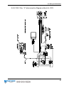
1
www.WhitakerBrothers.com
The Challenge Machinery Company provides owner's
manuals on its products solely as a courtesy to its customers.
See the information below before using this manual.
These manuals are for reference only. These manuals include products which are noncurrent, unsupported or no longer produced by The Challenge Machinery Company, and are
provided solely as an accomodation to our customers. By providing these manuals, The
Challenge Machinery Company makes no representation or warranty as to the products,
their current condition, or their suitability or fitness for use in any particular application, which
are the sole and independent responsibility of the product owner and user.
Older products may not comply with current safety procedures, guidelines or regulations,
and it is the product owner's and user's responsibility to evaluate the suitability and fitness of
the products in their current use and application. The Challenge Machinery Company makes
no representation, warranty or recommendation regarding any modifications which may be
required on non-current or unsupported products. The Challenge Machinery Company
assumes no liability for any modification or alteration to any Challenge product, and any such
modification or alteration to any Challenge product is not authorized by The Challenge
Machinery Company. The availability of these manuals is solely for the purpose of providing
reference information for the products.
This manual may not be complete in all aspects of product maintenance and repair. All
products should be used only by qualified and properly trained personnel, following proper
safety procedures. All products should be regularly inspected and maintained, and their condition,
application and use should be periodically evaluated by qualified personnel. Only qualified and
properly trained technicians should perform maintenance, repair and replacement
procedures. Attempting these procedures without proper training may cause machine
damage or operator injury!
Products may be unsupported by The Challenge Machinery Company due to age or the
unavailability of parts from their original manufacturer. No parts or product support will be
available to repair or maintain unsupported products. Older products may not be UL listed (if
the product does not have a UL label it is not a listed product), and may not comply with
applicable installation or other regulations or requirements if relocated to a new facility.
Many municipalities require a product to be UL listed before an electrician will connect power
to them. Often the cost of updating an older product to comply with current safety regulations is
greater than the value of the product.
Serial Numbers 070031A & Up
INSTRUCTION AND PARTS
MANUAL
iJOG
PAPER JOGGERS
Sold and Serviced by
The Challenge Machinery Company
6125 Norton Center Drive
Norton Shores, MI. 49441
www.challengemachinery.com
F.2-A
October 2007
1.0 Introduction
1.0 Introduction
THIS MANUAL is designed to help you get the most from your Challenge equipment. Keep this
manual in a safe, convenient place for quick reference by operators and service personnel.
SAFETY ALERT! This symbol means CAUTION: Personal safety
instructions! Pay special attention to the instructions in bold type. Personal injury may result if the
precautions are not read and followed.
READ THIS MANUAL BEFORE OPERATING! Follow precautions and instructions. If after reading
the manual, questions remain; please contact your Authorized Challenge Dealer.
Take a few minutes right now to RECORD YOUR MACHINE SERIAL NUMBER in the space
provided on the front cover of this manual. Also be sure to fill out the warranty card accompanying
your machine and return it DIRECTLY TO CHALLENGE.
If you bought a used machine, it is important to have the following information on record at Challenge.
Copy this page, fill in the information and send it care of The Challenge Service Department, 6125
Norton Center Drive, Norton Shores MI. 49441.
CHALLENGE MODEL iJOG
ATTN
SERIAL NUMBER
COMPANY
ADDRESS
CITY
PHONE
DEALER NAME & CITY
STATE/PROVINCE
DATE INSTALLED
ZIP
* WARRANTY INFORMATION *
It is very important that you read and understand the conditions outlined in the Warranty Information
Sheet attached to the outside of the shipping container of your machine.
The Warranty Information Sheet must be filled out completely and returned to THE CHALLENGE
MACHINERY COMPANY in order for the warranty to be issued for this machine.
Challenge® is a registered trademark of
The Challenge Machinery Company • 6125 Norton Center Drive • Norton Shores MI. 49441
Copyright© 2007 by The Challenge Machinery Company. All rights reserved. Printed in the U.S.A
2
1.0 Introduction
TABLE OF CONTENTS
1.0 Introduction ...................................................................................................................................... 2
2.0 Safety ............................................................................................................................................... 4
2.1 Precautions.................................................................................................................................. 4
2.2 Power Lockout Procedure ........................................................................................................... 4
2.3 Warning Label Definitions............................................................................................................ 5
3.0 Packing List...................................................................................................................................... 7
4.0 Specifications ................................................................................................................................... 8
5.0 Installation & Setup .......................................................................................................................... 9
5.1 Inspecting Shipment .................................................................................................................... 9
5.2 Uncrating ..................................................................................................................................... 9
5.3 Cleaning....................................................................................................................................... 9
5.4 Power Hook-Up ........................................................................................................................... 9
5.5 Mounting to Adjustable Stand (Optional)..................................................................................... 9
6.0 Operation ....................................................................................................................................... 10
6.1 Power / Speed Selection Switch (all models) ............................................................................ 10
6.2 Jogging (all models)................................................................................................................... 11
6.3 Air Jogging................................................................................................................................. 11
6.3.1 Three Modes of Jogging..................................................................................................... 11
6.3.2 Air Flow Adjustment ........................................................................................................... 11
6.3.3 Timer Adjustment ............................................................................................................... 11
6.4 Operating Tips ........................................................................................................................... 11
7.0 Troubleshooting/Maintenance........................................................................................................ 12
7.1 Troubleshooting ......................................................................................................................... 12
7.2 Blower Brush Replacement ....................................................................................................... 12
8.0 Parts List ........................................................................................................................................ 13
8.1 Footprint..................................................................................................................................... 13
8.2 66000-2 Main Assembly- iJOG with Air Sht. 1 ......................................................................... 14
8.3 66000-2 Main Assembly- iJOG with Air Sht. 2 ......................................................................... 16
8.4 66000-2 Main Assembly- iJOG with Air Sht. 3 ......................................................................... 18
8.5 66000-2 Main Assembly- iJOG with Air Sht. 4 .......................................................................... 20
8.6 66000-2 Main Assembly- iJOG with Air Sht. 5 ......................................................................... 22
8.7 66000-2 Main Assembly- iJOG with Air Sht. 6, 230V Option Parts.......................................... 24
8.8 66000-3 Main Assembly- iJOG without Air Sht. 1 ..................................................................... 26
8.9 66000-3 Main Assembly- iJOG without Air Sht. 2 ..................................................................... 28
8.10 66000-3 Main Assembly- iJOG without Air Sht. 3 ................................................................... 30
8.11 66000-3 Main Assembly- iJOG without Air Sht. 4 ................................................................... 32
8.12 66000-3 Main Assembly- iJOG without Air Sht. 5 (Aus).......................................................... 34
9.0 Wiring and Schematics .................................................................................................................. 36
9.1 E-3185 Rev. “A” Basic Machine Schematic- 120V.................................................................... 36
9.2 E-3180 Rev. “A” Interconnection Diagram with Air- 120V ......................................................... 37
9.3 E-3180-1 Rev. “A” Interconnection Diagram without Air- 120V................................................. 38
9.4 E-3189 Rev. “B” Basic Machine Schematic- 230V.................................................................... 39
9.5 E-3189 Rev. “A” Interconnection Diagram with Air- 230V ......................................................... 40
9.6 E-3189-1 Rev. “A” Interconnection Diagram without Air- 230V................................................. 41
3
2.0 Safety
2.0 Safety
2.1 Precautions
•
•
•
•
•
•
•
Safe use of this machine is the responsibility of the operator. Use good judgment and common
sense when working with and around this machine.
Read and understand all instructions thoroughly before using the machine. If questions remain,
contact the dealer from which you purchased this machine. Failure to understand the operating
instructions may result in personal injury.
DO NOT ALTER SAFETY GUARDS OR DEVICES. They are for your protection. Severe
personal injury may result.
Disconnect power before performing maintenance. See Section 2.2 Power Lockout Procedure.
Observe all caution labels on this machine.
Be sure there is sufficient power to operate the jogger properly.
If the jogger sounds or operates unusually, have it checked by a qualified service person.
2.2 Power Lockout Procedure
For maximum safety while making adjustments or repairs to your machine, be sure to disconnect
power to the machine. Disconnect the power plug from its socket.
Figure 1 - Main Power Disconnect
4
2.0 Safety
2.3 Warning Label Definitions
The following warning labels are found at various locations on your machine. Read and understand
the meaning of each symbol. If a label is lost from the machine, it should be replaced.
HAZARDOUS AREA
Disconnect power before cleaning, servicing, or making adjustments not requiring
power. Do not alter safety guards or devices; they are for your protection. Replace
all guards. Do not operate with any guards removed.
SHOCK HAZARD
Disconnect power before removing cover. Replace cover before operation.
5
2.0 Safety
!OJO!
This Este simbolo de alerta de seguridad significa ¡ OJO ! INSTRUCCIONES DE SEGURIDADPERSONAL. Lea las instrucciones porque se refieren a su
seguridad personal. Fall de obedecer las instrucciones que siguen podria resultar en lesiones
corporales.
•
•
•
•
•
•
•
•
•
•
•
•
•
•
•
•
•
•
•
•
Esta maquina, junto con sus mecanismos de seguridad, esta disenada para ser manejada por
UNA SOLA PERSONA a la vez. Jamas debe ser manejada por mas de una persona al mismo
tiempo.
La seguridad es la responsabilidad del operario que usa esta maquina.
LEA DETENIDAMENTE el manual de instrucciones y las PRECAUCIONES DE SEGURIDAD
antes de poner a funcionar la cortadora. Pidale a su supervisor una copia.
El manejo de la guillotina debe estar exclusivamente a cargo de personal entrenado y autorizado
para ello.
NO MODIFIQUE LOS MECANISMOS DE SEGURIDAD, estan ahi para su proteccion no deben
ni modificarse ni quitarse.
DESCONECTE LA CORRIENTE ELECTRICA antes de proceder a hacerle servicio de limpieza,
engrasar, o de hacer adjustes que no requieren corriente. Trabe el interruptor en la posicion
OFF (apagado); vea “Procedimiento para cortar la corriente electrica” al pie de esta pagina.
Eche llave a la guillotina y quite la llave cuando la maquina no esta en operacion; vea “Corriente
electrica”.
Asegurese de que la guillotina este debidamente a tierra. Vea “Conexion de la fuerza electrica”.
Verifique el voltaje y asegurese de que este sea suficiente para el debido funcionamiento de la
guillotina.
Preste atencion a todas las placas con advertencias instaladas en esta guillotina.
No permita que objetos estranos esten en la mesa o cerca de la cuchilla cortadora.
TENGA SUMO CUIDADO al tocar y cambiar la cuchilla. Heridas severas y hasta
desmembramiento pueden resultar del manejo sin cuidado o negligente.
El suelo alrededor de la guillotina debe mantenerse despejado y libre de recortes, desperdicios,
aceite y grasa.
Al haber la necesidad de reemplazar partes hidraulicas, afloje todas las conexiones poco a poco
para dejar escapar la presion. Jamas debe aflojarse conexiones mientras la maquina este
andando.
Si la guillotina empezara a sonar o trabajar diferentemente a lo acostumbrado, desconectela y
consulte la seccion “Troubleshooting” (Reparador) de este manual. Si no es posible corregir el
problema, llame a su servicio autorizado para que le examinen la maquina.
PELIGRO DE MACHUQUE - Mantenga manos y dedos fuera de la agarradera mientras sujeta el
papel. Use el calibrador trasero y su rueda de mano para empujar el papel cortado. NO PONGA
SUS MANOS BAJOLA CUCHILLA O AREA DE LA AGARRADERA.
NO OPERE SIN LAS GUARDAS PROTECTORAS!
¡ OJO ! PRECAUCION -
Como proceder para desconectar
la corriente electrica.
Para maxima seguridad durante ajustes y reparaciones de su maquina, verifique bien que el interruptor principal
de control de corriente al cual la maquina esta conectada, este desconectado. El interruptor deba ser puesto en
la posicion “OFF” (desconectado) y se debe poner un candado en la anilla. La llave del candado debe ser
guardada por la persona que estara efectuando los trabajos de servicio o de reparacion en la guillotina.
Desconecte la corriente electrica antes de proceder a hacer cualquier ajuste o reparacion o de efectuar el
engrase en cualquier maquina.
6
3.0 Packing List
3.0 Packing List
Part No.
iJOG
Description
Paper Jogger
Qty.
1
Optional Items
Part No.
A-6822-1
Description
Heavy Duty Stand
Qty.
1
7
4.0 Specifications
4.0 Specifications
Description
Air Assist Version
Paper Sizes
Runs with air always on
Runs with air off
Runs in air timer mode
Low and high jog settings
Footswitch operated
Adjustable air flow
Will jog collated sets
120V, 60HZ, 15 Amp
Dimensions
Overall Height
Overall Width
Overall Depth
Overall Height w/Optional Stand
Net Weight
Non-Air Assist Version
Paper Sizes
Low and high jog settings
Footswitch operated
Will jog collated sets
120V, 60HZ, 5 Amp
Dimensions
Overall Height
Overall Width
Overall Depth
Overall Height w/Optional Stand
Net Weight
Inch Units
Metric Units
12” x 18” x 4”
A3 x 101 cm
21”
23”
20”
48”
75 lb.
53 cm
58 cm
51 cm
122 cm
34 kg
12” x 18” x 4”
A3 x 101 cm
21”
22”
17”
48”
70 lb.
53 cm
56 cm
43 cm
122 cm
32 kg
Sound Emission
93 dB without air, 88 db with air (ear protection recommended)
Challenge reserves the right to make changes to any product or specification without notice and
without incurring responsibility to existing units.
8
5.0 Installation & Setup
5.0 Installation & Setup
5.1 Inspecting Shipment
This machine has been carefully packed to prevent damage during shipment. However, claims for
damage or loss are the responsibility of the recipient. Inspect all shipments as soon as they are
received. If there is any noticeable damage, note it on the freight bill. Visual and/or hidden damage
must be reported to the claims department of the carrier within 15 days. Contact your dealer if you
need any assistance. Check the contents of the box against the packing list on page 7. Make sure
there are no missing items.
5.2 Uncrating
The iJOG weighs approximately 70 lbs (26 kg). DO NOT risk personal injury or damage by
attempting to move machinery with makeshift equipment or inadequate help. This machine is
shipped in a corrugated carton. Open the lid and remove the fillers. Carefully lift machine out of the
carton and set on a work surface or optional stand (see section 5.5 Mounting to Adjustable Stand).
5.3 Cleaning
After unpacking, wipe down all machine panels and surfaces with a clean cloth.
5.4 Power Hook-Up
SHOCK HAZARD! Possible shock could cause personal injury or death.
Connect the plug to any standard 120 Volt outlet.
Figure 2 – Power Hook-Up
5.5 Mounting to Adjustable Stand (Optional)
Remove the stand and casters from their box. Assemble the casters to the stand using a ¾” wrench.
Assemble the tube and adjust it to you preferred height. Lock it in place using the two ½-13 bolts
(3/4” wrench) and ½” lock washers provided
Using at least two people, place the machine on the stand. Line up four holes in the top shelf of the
stand with four holes on the underside of the machine base. Fasten the machine to the stand using
four 5/16-18 screws (1/2” wrench) provided with the stand.
9
6.0 Operation
6.0 Operation
IMPORTANT: DO NOT ATTEMPT TO OPERATE THE JOGGER UNTIL
YOU HAVE THOROUGHLY READ AND UNDERSTAND ALL OF THE FOLLOWING
INSTRUCTIONS. CALL YOUR AUTHORIZED CHALLENGE DEALER IF YOU STILL HAVE ANY
QUESTIONS.
Blower Control Switch
Time Control
Air Flow Control
Power/Jog Speed
Figure 3 – Machine Controls
6.1 Power / Speed Selection Switch (all models)
The power/speed selection switch is located at the lower left-hand corner of the machine. Power is
off when the switch is in its center position. Press the switch to the down position to set the jogger to
its lower speed. Press the switch to the up position to set the jogger to its higher speed. Note that
the machine always has power unless the switch is set to the center position. Set it as follows:
Mode
Higher Speed
Off
Lower Speed
Switch Position
Up
Center
Down
Tip! The lower speed setting is recommended for most applications.
10
6.0 Operation
6.2 Jogging (all models)
Be aware that the nature of jogging paper is loud. Select a jogging speed. Place a paper pile into the
jogging tray. Depress the foot switch. Gently tamp the edges of the pile until the pile is adequately
jogged. Release the foot switch and continue tamping until the motor stops. Remove the pile.
6.3 Air Jogging
The following section describes the operation of air assist model of the iJOG.
6.3.1 Three Modes of Jogging
The air assist feature can be set to three different modes: air on all the time the foot switch is
depressed, air on for an adjustable period of the time the foot switch is being depressed, and air off.
The Blower control switch is located at the right rear corner of the machine. Set it as follows:
Mode
Timer Mode
Always On
Off
Switch Position
Up
Center
Down
6.3.2 Air Flow Adjustment
The amount of airflow can be set from zero to maximum. The air flow adjustment knob is located
next to the Blower switch. Turning the knob counter-clockwise decreases the air flow. Turning it
clockwise increases air flow.
A medium to low setting is recommended for most applications.
6.3.3 Timer Adjustment
The amount of time the blower runs while the foot switch is depressed can be adjusted to a maximum
of approximately 10-12 seconds. Turning the knob counter-clockwise decreases the time while
turning it clockwise increases the time.
A medium to low setting is recommended for most applications.
6.4 Operating Tips
•
•
•
•
Ear protection is recommended if operating for extended periods of time.
If the machine is placed on a bench, a lip should be added to the edge of the bench to
prevent the machine from sliding off.
The rubber feet should be kept clean to prevent the machine from sliding.
Medium to low settings are recommended for most applications and will extend the life of the
machine.
11
7.0 Troubleshooting/Maintenance
7.0 Troubleshooting/Maintenance
7.1 Troubleshooting
Problem
Motor(s) won’t turn on
Jogger runs but blower won’t
Jogger motor runs but won’t jog
Possible Cause
Power switch turned off, unplugged, blown fuse,
circuit breaker tripped, brushes worn, loose wires
Blower switched off, blown fuse, brushes worn,
control circuit board damaged, loose wires
Eccentric weight on motor loosened
7.2 Blower Brush Replacement
1. Switch the machine off and disconnect the power cord.
2. Remove one side cover from the machine.
3. To remove the switch box from the machine, remove (4) screws that attach it to the back side of
the machine.
4. Rock back and forth while pulling on each of the (2) green terminal plugs to disconnect them form
the circuit board.
5. Each brush assembly is held in place with by a bracket that is held down with (2) screws.
Remove the brackets by removing the screws.
6. DO NOT CUT OR UN-CRIMP THE WIRES FROM THE BRUSH ASSEMBLY. Each wire is
attached to a thin strip of metal that is inserted into the brush assembly.
7. Using a small screwdriver, pry between the wire and the casing to remove the strip of metal
attached to the wire.
8. The first half of the strip will slide out easily. It will lock when it is half-way out. Use a thin
screwdriver to push down the locking tab that is on the strip of metal. Pull the strip of metal while
pushing the locking tab.
9. Install the new brush assembly in the reverse order of which the old one was removed. Always
replace both brushes at the same time.
10. Firmly re-insert the (2) green terminal plugs into the circuit board.
11. Reinstall the switch box to the back of the machine.
12. Reinstall the side cover.
13. Reconnect the power cord.
12
8.0 Parts List
8.0 Parts List
8.1 Footprint
13
8.0 Parts List
8.2 66000-2 Main Assembly- iJOG with Air Sht. 1
14
8.0 Parts List
Main Assembly- iJOG with Air
66000-2 Sht. 1
ITEM
1
2
3
4
5
6
7
8
9
10
11
PART NO.
66004-1
66005-1
66011-1
66024
66025
E-1600-201
E-1736-2
E-2191-2
H-6910-420SS
H-6918-403
S-1350-16
DESCRIPTION
QTY
TUBE
1
ECCENTRIC WEIGHT
1
JOGGING TRAY
1
REINFORCEMENT PLATE
1
REINFORCEMENT PLATE
1
3500 RPM DC MOTOR
1
QUENCHARC
1
3/4 CONDUIT FITTING
2
SCREW - 1/4-20 X 2-1/2 BUT. HEAD CAP STAINLESS 4
SCREW - 1/4-20 X 3/8 SOCKET HEAD CAP
1
STRAIN RELIEF BUSHING
1
15
8.0 Parts List
8.3 66000-2 Main Assembly- iJOG with Air Sht. 2
16
8.0 Parts List
Main Assembly- iJOG with Air
66000-2 Sht. 2
ITEM
1
2
3
4
5
6
7
8
9
10
11
12
13
14
15
16
17
18
19
20
21
22
23
24
25
26
27
PART NO.
14050
40016-8
66001-1
66007
66016
E-530-13
E-1140-17
E-1143
E-2189-2
E-2190-2
E-2626-4
EE-3191
EE-3192
H-6417-5
H-6423-4
H-6899-1004
H-6910-408
H-6918-102404
H-6918-63204
H-6924-004
H-7324-8
H-7324-#10
H-7324-#6
H-7327-10
S-1350-16
S-1781-164
S-1781-42
DESCRIPTION
SERIAL PLATE
MOUNT - VIBRATION
BASE WELDMENT
VACUUM MOTOR
LEVELING PAD
FUSE HOLDER- FUSE W/CAP (INCHES)
ROCKER SWITCH
BRIDGE RECTIFIER
TUBING- CORRUGATED FLEXIBLE
3/4 CONDUIT FITTING
TERMINAL STRIP (4P)
POWER CORD - 120V
FOOT SWITCH ASSEMBLY
NUT - 5/16-18 HEX
NUT - 1/4-20 HEX KEP
"SCREW - #10 X 1/2 PHIL PAN SELF-TAP,F"
SCREW - 1/4-20 X 1 BUTTON HEAD CAP
SCREW - #10-24 X 1/2 SOCKET HEAD CAP
SCREW - #6-32 X 1/2 SOCKET HEAD CAP
SCREW - #0 X 1/4 DRIVE SCREW
WASHER - 1/4 INT TOOTH
WASHER - #10 INT TOOTH
WASHER - #6 INT TOOTH
WASHER - 5/16 MEDIUM LOCK
STRAIN RELIEF BUSHING
POWER LABEL
LABEL - GROUND
QTY
1
3
1
1
4
1
1
1
1
2
1
1
1
3
6
4
1
1
2
2
2
1
2
3
2
1
1
17
8.0 Parts List
8.4 66000-2 Main Assembly- iJOG with Air Sht. 3
18
8.0 Parts List
Main Assembly- iJOG with Air
66000-2 Sht. 3
ITEM
1
2
3
PART NO.
66011-1
H-6910-503SS
H-6910-504SS
DESCRIPTION
QTY
JOGGING TRAY
1
SCREW - 5/16-18 X 3/8 BUT. HEAD CAP STAINLESS
2
SCREW - 5/16-18 X 1/2 BUT. HEAD CAP STAINLESS
1
19
8.0 Parts List
8.5 66000-2 Main Assembly- iJOG with Air Sht. 4
20
8.0 Parts List
Main Assembly- iJOG with Air
66000-2 Sht. 4
ITEM
1
1
2
3
4
5
6
7
8
9
10
11
12
13
14
15
16
17
18
19
PART NO.
EE-3226
EE-3227
35126-3
66001-1
66008
E-530-13
E-1140-17
E-1152-56
E-3181
EE-3179
H-6423-#10
H-6423-#6
H-6910-102403
H-6910-102404
H-7324-#10
H-6910-63203
S-1781-160
S-1781-163
S-1781-42
S-1781-50
DESCRIPTION
CONTROL BOX ASSEMBLY – 120V OPTION
CONTROL BOX ASSEMBLY – 230V OPTION
KNOB
BASE WELDMENT
VACUUM COVER
FUSE HOLDER- FUSE W/CAP (INCHES)
ROCKER SWITCH
STANDOFF
ISOLATION SHIELD- POTENTIOMETER
CIRCUIT BOARD
NUT - #10-24 HEX KEP
NUT - #6-32 HEX KEP
SCREW - #10-24 X 3/8 BUTTON HEAD CAP
SCREW - #10-24 X 1/2 BUTTON HEAD CAP
WASHER - #10 INT TOOTH
SCREW - #6-32 X 3/8 BUTTON HEAD CAP
LABEL - FUSE 7A SB
BLOWER LABEL
LABEL - GROUND
LABEL - ELECTRIC SHOCK
QTY
1
1
REF
REF
REF
REF
REF
REF
REF
REF
REF
REF
4
REF
REF
REF
REF
REF
REF
REF
21
8.0 Parts List
8.6 66000-2 Main Assembly- iJOG with Air Sht. 5
22
8.0 Parts List
Main Assembly- iJOG with Air
66000-2 Sht. 5
ITEM
1
2
3
4
5
6
PART NO.
66001-1
66006
H-6910-403
S-1781-15
S-1781-165
S-1781-50
DESCRIPTION
BASE WELDMENT
SIDE COVER
SCREW - 1/4-20 X 3/8 BUTTON HEAD CAP
LABEL - MOVING PARTS HAZARD
LABEL - FUSE 5A SB
LABEL - ELECTRIC SHOCK
QTY
1
2
18
2
1
2
23
8.0 Parts List
8.7 66000-2 Main Assembly- iJOG with Air Sht. 6, 230V Option Parts
24
8.0 Parts List
Main Assembly- iJOG with Air 230V Option Parts
66000-2 Sht. 6
ITEM
1
2
3
4
5
6
7
8
9
10
11
PART NO.
66007-1
E-889-1
E-2742-12
EE-2778-3
EE-3179-1
EE-3190-1
H-6423-#10
H-6918-102404
H-7321-#10
S-1033-10
S-1781-166
DESCRIPTION
VACUUM MOTOR- 230V
FUSE- 1.5 A SB
TRANSFORMER
POWER CORD - 120V
CIRCUIT BOARD- 230V OPTION
PLUG ASSEMBLY- POTENTIOMETER- 230V
NUT - #10-24 HEX KEP
SCREW - #10-24 X 1/2 SOCKET HEAD CAP
WASHER - #10 SAE PLAIN
PLUG- MALE, SIDE ENTRY
LABEL - FUSE 1.5A SB
QTY
1
1
1
1
1
1
4
4
4
1
1
25
8.0 Parts List
8.8 66000-3 Main Assembly- iJOG without Air Sht. 1
26
8.0 Parts List
Main Assembly- iJOG without Air Sht. 1
66000-3 Sht. 1
ITEM
1
2
3
4
5
6
7
8
9
10
11
PART NO.
66004-1
66005-1
66015-1
66024
66025
E-1237-1
E-1600-201
E-1736-2
H-6910-420SS
H-6918-403
S-1350-16
DESCRIPTION
QTY
TUBE
1
ECCENTRIC WEIGHT
1
NON-AIR JOGGING TRAY
1
REINFORCEMENT PLATE
1
REINFORCEMENT PLATE
1
WIRE NUT - RED
2
3500 RPM DC MOTOR
1
QUENCHARC
1
SCREW - 1/4-20 X 2-1/2 BUT. HEAD CAP STAINLESS 4
SCREW - 1/4-20 X 3/8 SOCKET HEAD CAP
1
STRAIN RELIEF BUSHING
1
27
8.0 Parts List
8.9 66000-3 Main Assembly- iJOG without Air Sht. 2
28
8.0 Parts List
Main Assembly- iJOG without Air Sht. 2
66000-3 Sht. 2
ITEM
1
2
3
4
5
6
7
8
PART NO.
40016-8
66001-1
66015-1
E-2196-22
H-6417-5
H-6910-503SS
H-6910-504SS
H-7327-10
DESCRIPTION
QTY
MOUNT - VIBRATION
3
BASE WELDMENT
1
NON-AIR JOGGING TRAY
1
HOLE PLUG 2
NUT - 5/16-18 HEX
3
SCREW - 5/16-18 X 3/8 BUT. HEAD CAP STAINLESS
2
SCREW - 5/16-18 X 1/2 BUT. HEAD CAP STAINLESS
1
WASHER - 5/16 MEDIUM LOCK
3
29
8.0 Parts List
8.10 66000-3 Main Assembly- iJOG without Air Sht. 3
30
8.0 Parts List
Main Assembly- iJOG without Air Sht. 3
66000-3 Sht. 3
ITEM
1
2
3
4
5
6
7
8
9
10
11
12
13
14
15
16
17
18
19
PART NO.
14050
66016
E-530-13
E-1140-17
E-1143
E-2626-4
EE-3191
EE-3192
H-6423-4
H-6910-408
H-6918-102404
H-6918-63204
H-6924-004
H-7324-8
H-7324-#10
H-7324-#6
S-1350-16
S-1781-164
S-1781-42
DESCRIPTION
SERIAL PLATE
LEVELING PAD
FUSE HOLDER- FUSE W/CAP (INCHES)
ROCKER SWITCH
BRIDGE RECTIFIER
TERMINAL STRIP (4P)
POWER CORD - 120V
FOOT SWITCH ASSEMBLY
NUT - 1/4-20 HEX KEP
SCREW - 1/4-20 X 1 BUTTON HEAD CAP
SCREW - #10-24 X 1/2 SOCKET HEAD CAP
SCREW - #6-32 X 1/2 SOCKET HEAD CAP
SCREW - #0 X 1/4 DRIVE SCREW
WASHER - 1/4 INT TOOTH
WASHER - #10 INT TOOTH
WASHER - #6 INT TOOTH
STRAIN RELIEF BUSHING
POWER LABEL
LABEL - GROUND
QTY
1
4
1
1
1
1
1
1
6
1
1
2
2
1
1
2
2
1
1
31
8.0 Parts List
8.11 66000-3 Main Assembly- iJOG without Air Sht. 4
32
8.0 Parts List
Main Assembly- iJOG without Air Sht. 4
66000-3 Sht. 4
ITEM
1
2
3
4
5
6
7
8
PART NO.
66001-1
66006
66013
H-6910-102403
H-6910-403
S-1781-15
S-1781-165
S-1781-50
DESCRIPTION
BASE WELDMENT
SIDE COVER
BACK COVER
SCREW - #10-24 X 3/8 BUTTON HEAD CAP
SCREW - 1/4-20 X 3/8 BUTTON HEAD CAP
LABEL - MOVING PARTS HAZARD
LABEL - FUSE 5A SB
LABEL - ELECTRIC SHOCK
QTY
1
2
1
4
18
2
1
2
33
8.0 Parts List
8.12 66000-3 Main Assembly- iJOG without Air Sht. 5 (Aus)
34
8.0 Parts List
Main Assembly- iJOG without Air Sht. 5
66000-3 Sht. 5
ITEM
1
2
3
4
5
6
7
8
PART NO.
E-889-1
E-2742-12
EE-2778-3
H-6423-#10
H-6918-102404
H-7321-#10
S-1033-10
S-1781-166
DESCRIPTION
FUSE- 1.5 A SB
TRANSFORMER
POWER CORD - 120V
NUT - #10-24 HEX KEP
SCREW - #10-24 X 1/2 SOCKET HEAD CAP
WASHER - #10 SAE PLAIN
PLUG- MALE, SIDE ENTRY
LABEL - FUSE 1.5A SB
QTY
1
1
1
4
4
4
1
1
35
9.0 Wiring and Schematics
9.0 Wiring and Schematics
9.1 E-3185 Rev. “A” Basic Machine Schematic- 120V
36
9.0 Wiring and Schematics
9.2 E-3180 Rev. “A” Interconnection Diagram with Air- 120V
37
9.0 Wiring and Schematics
9.3 E-3180-1 Rev. “A” Interconnection Diagram without Air- 120V
38
9.0 Wiring and Schematics
9.4 E-3189 Rev. “B” Basic Machine Schematic- 230V
39
9.0 Wiring and Schematics
9.5 E-3189 Rev. “A” Interconnection Diagram with Air- 230V
40
9.0 Wiring and Schematics
9.6 E-3189-1 Rev. “A” Interconnection Diagram without Air- 230V
41
F.2-A
October 2007