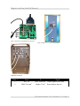
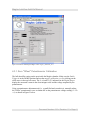
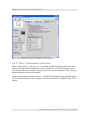
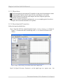
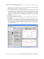
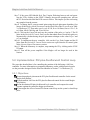
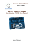
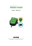
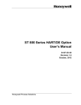
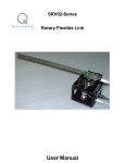
1
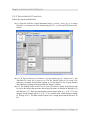
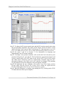
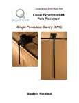
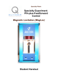
Specialty Plants Specialty Experiment: PIV-plus-Feedforward Position Control Magnetic Levitation Plant LabView Add-On Manual Maglev LabView Add-On Manual Table of Contents 1. Objectives............................................................................................................................1 2. Prerequisites.........................................................................................................................1 3. References............................................................................................................................1 4. Maglev Setup using LabView.............................................................................................1 4.1. Experimental Setup Components.................................................................................1 4.2. Experimental Setup and Wiring...................................................................................2 4.3. Calibration Procedure..................................................................................................4 4.3.1. Zero "Offset" Potentiometer Calibration..............................................................5 4.3.2. "Gain" Potentiometer Calibration........................................................................6 4.4. Pre-Lab Assignments...................................................................................................7 5. In-Lab Procedure.................................................................................................................7 5.1. Implementation: PI Current Control Loop...................................................................7 5.1.1. Objectives.............................................................................................................8 5.1.2. Experimental Procedure.......................................................................................8 5.2. Implementation: PIV-plus-Feedforward Control Loop.............................................10 5.2.1. Objectives...........................................................................................................10 5.2.2. Experimental Procedure.....................................................................................11 Document Number: 616 Revision: 01 Page: i Maglev LabView Add-On Manual 1. Objectives This manual describes an in-lab procedure for the Quanser Magnetic Levitation specialty plant when using the a LabView controller (as opposed to a WinCon controller as in Reference [2]). Section 4.2 summarizes the wiring of the Coupled-Tank plant with the Quanser-National Instruments Terminal board. Section 4.3 explains how to calibrate the pressure sensors on the plant using a supplied LabView virtual instrument (VI). The laboratory procedure for running the current controller Maglev experiment using a predesigned LabView VI is given in Section 5.1. This procedure deals with controlling the current in the electromagnet coils. The laboratory procedure for controlling the position of the ball on the Maglev plant is given in Section 5.2 using another pre-designed LabView VI. 2. Prerequisites To successfully carry out this laboratory, the prerequisite are: i) To be familiar with your Maglev main components (e.g. actuator, sensors), your data acquisition card (e.g. NI E-Series or M-Series), and your power amplifier (e.g. UPM). See References [1] for information on the maglev hardware, Reference [4] for further information on the power amplifier, and the corresponding National Instrument Data Acquisition User Manual for your NI DAC card. ii) To be familiar in using LabView to control and monitor the plant as well as designing their controller through LabView. iii) To be familiar with the complete wiring and operating procedure of your Maglev specialty plant, as discussed in Reference [1]. 3. References [1] Maglev User Manual. [2] Maglev Control Laboratory – Student Manual. [3] Maglev Control Laboratory – Instructor Manual. [4] Universal Power Amplifier 4. Maglev Setup using LabView 4.1. Experimental Setup Components To setup this experiment, the following hardware and software are required: Power Module: Quanser UPM 2405, or equivalent. Document Number: 616 Revision: 01 Page: 1 Maglev LabView Add-On Manual Data Acquisition Board: Quanser Q4/Q8 or National Instrument E-Series, M-Series, or equivalent. Maglev: Quanser Magnetic Levitation Plant, as shown in title page. LabView Software: The National Instruments LabView software with the Control Design and the PID Control toolkit installed. Ensure the Control Design Tookit and the PID Control Toolkit are installed in LabView. Otherwise "VI Missing" errors will be prompted when opening maglev_current_control_pi.vi or the maglev_position_control_piv.vi. 4.2. Experimental Setup and Wiring In Reference [1], see Section 4 for the more detailed wiring procedure, Section 2 for a description of the Maglev components, and Section 4 for a description of the different configuration schemes and setup information. Figure 1, Figure 2, and Figure 3 describe the wiring to interface the Magnetic Levitation specialty plant with the Quanser-NI Terminal Board for use with a National Instruments Data Acquisition Card. If a Quanser Q4 or Q8 board is being used with LabView, please see Section 4 in Reference [1] for a description of the wiring. The cable labels in Figures 1, 2, and 3 correspond to the connections summarized in Table 1. Document Number: 616 Revision: 01 Page: 2 Maglev LabView Add-On Manual Figure 1 Quanser-NI Terminal Board Connections Figure 2 Maglev Connections Figure 3 Universal Power Module UPM 2405 Connections Cable # From 1 DAC #0 2 UPM "To Load" To Signal UPM "From D/A" Control signal to the UPM. Maglev "Coil" Power leads to the coil. Document Number: 616 Revision: 01 Page: 3 Maglev LabView Add-On Manual Cable # From To Signal 3 UPM "To A/D" Quanser-NI Terminal Board: S1 to ADC #0 S3 to ADC #2 Position and current feedback signals to the data acquisition terminal board, through the UPM. 4 Maglev "Sensor" UPM "S1 & S2" Position feedback signal to the UPM. 5 Maglev "Current" UPM "S3" Current feedback signal to the UPM. Table 1 Maglev Wiring Summary 4.3. Calibration Procedure This calibration procedure described in this section is to calibrate the "Gain" and "Offset" potentiometers that are described in Section 2 in Reference [1]. The LabView virtual instrument called maglev_calibration_zz.vi shown in Figure 4 below can be used to calibrate the ball position sensor of the Maglev experiment. The zz suffix denotes the type of data acquisition board that is being used to interface with the Maglev device. For example, "ni" is for an E-Series or M-Series board and "q8" is for the Quanser Q8 board. Before going through the calibration procedure, follow the guidelines given in the beginning of Section 5.0 and the beginning of Section 5.2 in Reference [1]. Document Number: 616 Revision: 01 Page: 4 Maglev LabView Add-On Manual Figure 4 VI used for calibrating the Maglev sensor: maglev_calibration_ni.vi. 4.3.1. Zero "Offset" Potentiometer Calibration The ball should be resting on the post inside the Maglev chamber. Make sure the Switch Trigger is in the DOWN position and run the maglev_calibration_zz.vi by clicking on the white arrow in the top-left corner. The Ic (A) and Vb (V) indicators in the Digital Scopes display the measured current in the electromagnet coils and the voltage outputted by the potentiometer. Using a potentiometer adjustment tool (i.e. a small flat-head screwdriver), manually adjust the "Offset" potentiometer screw to obtain 0 V on the potentiometer voltage reading, i.e. Vb = 0, as shown in Figure 5 below. Document Number: 616 Revision: 01 Page: 5 Maglev LabView Add-On Manual Figure 5 maglev_calibration.vi running with potentiometer offset calibrated. 4.3.2. "Gain" Potentiometer Calibration Make sure the maglev_calibration_zz.vi is running with the ball resting on the post. Place the Switch Trigger in the UP position to feed a current of 2 A in the electromagnet coils. The should cause the steel ball to jump up to the face of the electromagnet. If not, place the ball manually on the face of the magnet. Using a potentiometer adjustment tool (i.e. a small flat-head screwdriver), manually adjust the "Gain" potentiometer screw to obtain a value between 4.75 V and 4.95 V on the Vb (V) display. Document Number: 616 Revision: 01 Page: 6 Maglev LabView Add-On Manual Figure 6 maglev_calibration.vi running with potentiometer 1 gain calibrated. When finished calibrating, click on the STOP VI button to stop running the virtual instrument. 4.4. Pre-Lab Assignments See Section 6 in Reference [2] for the pre-lab exercises and Section 6 in Reference [3] for the corresponding solutions. 5. In-Lab Procedure 5.1. Implementation: PI Current Control Loop The procedure detailed here is for controlling the electromagnet current in the Maglev plant using a LabView VI. For more information on comparing laboratory results with theoretical results see the procedure designed for the WinCon controller in Section 7.2 of Reference [2]. Document Number: 616 Revision: 01 Page: 7 Maglev LabView Add-On Manual 5.1.1. Objectives To tune through pole placement the PI controller for the actual electromagnet current. To implement in LabView the PI control for the actual Maglev coil current. To run the obtained PI controller and compare the actual response against the controller design specifications. To run the system's simulation simultaneously, at every sampling period, in order to compare the actual and simulated level responses. 5.1.2. Experimental Procedure Follow the steps described below: Step 1. Open the LabView virtual instrument maglev_current_control_pi_zz.vi shown in Figure 7 (zz denotes the DAC board being used, i.e. ni is for an NI E-Series or MSeries). Figure 7 maglev_current_control_pi_zz.vi used to control current in Maglev plant. Step 2. In Signal Generator Parameters, set the signal type to a square wave, the Document Number: 616 Revision: 01 Page: 8 Maglev LabView Add-On Manual Amplitude to 1 A, and the Frequency to 0.15 Hz. This generates a current command that goes between 0 A and 1 A (only positive current). Step 3. The default values in the Control Parameters panel are set to the values that meet the desired specifications as detailed in Reference [2] and Reference [3]. Thus the proportional current control gain kp_c is 66.7 V/A, the integral current control gain ki_c is 23.3 V/A/s, and the max integral windup IC Windup is 24 V. Note that the filter cutoff frequency is set to by default to 24 Hz but is not used in this controller. Step 4. Set the sampling rate in to 500 Hz. Step 5. Make sure the Start Maglev button is pressed to enable the control when the VI is running. Step 6. Run the VI by clicking on the white arrow button located in the top-left corner of the window. The red measured current should be tracking the desired blue current in the Current (A) scope, as shown in Figure 8. Also, the voltage being applied to the coils should not be saturated by the amplifier continuously (i.e. 24 V when using the Quanser UPM-2405). Figure 8 Current controller response. Document Number: 616 Revision: 01 Page: 9 Maglev LabView Add-On Manual Step 7. If the green LED labeled Real Time? begins flickering between red and green: stop the VI by clicking to the STOP VI button, decrease the sampling rate, and run the VI. Re-iterate this until the LED ceases to flicker. This implies you are not loosing any samples from the sensors. Step 8. To change the PI current control gains using the pole-placement algorithm, first ensure all the Maglev Model Parameters in the Model tab of the VI are set as in Table 3 of Reference [1]. Thus make sure Lc to 0.412 H, Rc to 10 Ohms, Km to 6.35e-5, Rs to 1 Ohm, Mb to 0.068 kg, and Tb to 0.014 m. Step 9. Click on the Control tab and vary the position of the poles pc1 and pc2. The PI gains in the Desired PI Control Gains section that obtain those closed-loop poles are automatically calculated using the pole-placement technique as the values of pc1 and pc2 are changed. Step 10. To implement the new controller, click on the Copy Gains button and the PI gains from the Desired PI Control Gains section are copied into the PI control gains in the Current Control Parameters section. Step 11. When the laboratory is complete, stop running the VI by clicking on the STOP VI button. Step 12. Turn off the power amplifier if the Maglev will no longer be used in this session. 5.2. Implementation: PIV-plus-Feedforward Control Loop The procedure detailed here is for controlling the position of the ball using a LabView controller. For more information on comparing laboratory results with theoretical results see the procedure designed for the WinCon controller in Section 7.3 of Reference [2]. 5.2.1. Objectives To tune through pole placement the PIV-plus-Feedforward controller for the actual Maglev ball position. To implement in LabView the PIV-plus-feedforward control for the actual Maglev ball position. To run the obtained PI-plus-feedforward level controller and compare the actual response against the controller design specifications. To investigate the effect of nested PI current control loop on the system's closed-loop poles. Document Number: 616 Revision: 01 Page: 10 Maglev LabView Add-On Manual 5.2.2. Experimental Procedure Follow the steps described below: Step 1. Open the LabView virtual instrument maglev_position_control_piv_zz.vi shown in Figure 9 (zz denotes the DAC board being used, i.e. ni is for an NI E-Series or MSeries). Figure 9 maglev_position_control_piv_zz.vi used to control current in Maglev plant. Step 13. In Signal Generator Parameters, set the signal type to a square wave, the Amplitude to 0 mm, the Frequency to 0.20 Hz, and the Offset to 14.0 mm. This generates a constant ball position setpoint at 14 mm which is the air gap distance when the ball is resting on the post inside the Maglev chamber. Step 14. The default values in the Current Control Parameters panel in the Magnet tab are set to the values that meet the desired specifications as detailed in Reference [2] and Reference [3]. Thus the proportional current control gain kp_c is 66.7 V/A, the integral current control gain ki_c is 23.3 V/A/s, and the max current integral windup IC Windup is 24 V. The filter cutoff frequency for viewing the measured current is 10 Hz. Document Number: 616 Revision: 01 Page: 11 Maglev LabView Add-On Manual Step 15. Similarly, the default values in the Position Control Parameters panel in the Ball Pos tab are set to the values that meet the desired specifications as detailed in Reference [2] and Reference [3]. Thus the feed-forward gain is set to 142.9 A/m, the feed-forward control factor is 0.5, the proportional ball position control gain kp_p is -252.6 A/m, the velocity ball position control gain kv_p is -4.29 A.s/m, the integral ball position control gain ki_p is -248.1 A/m/s, the max ball position integral windup XB Windup is 1 A. The low-pass filter cutoff frequency used in the proportional control and for viewing, called fc1_b, is set to 40.0 Hz. The cutoff frequency of the second-order high-pass filter used in the ball position velocity control, fc2_b, is set to 70 Hz. Setting these cutoff frequencies properly are as important as the control gains for stabilizing the ball. Step 16. Set the sampling rate in to 500 Hz. Step 17. Make sure the Start Maglev button is pressed to enable the control when the VI is running. Step 18. Run the VI by clicking on the white arrow button located in the top-left corner of the window. In about 10-15 seconds, the current should increase enough such that the red measured position begins to be stabilized about the desired blue position in the Position (mm) scope, as shown in Figure 10. This is the initial startup phase when running the Maglev. Document Number: 616 Revision: 01 Page: 12 Maglev LabView Add-On Manual Figure 10 Initial position controller response. Step 19. If the green LED labeled Real Time? begins flickering between red and green: stop the VI by clicking to the STOP VI button, decrease the sampling rate, and run the VI. Re-iterate this until the LED ceases to flicker. This implies you are not loosing any samples from the sensors. Step 20. Begin to gradually decrease the Offset (mm) in the Signal Generator Parameters until the the setpoint of the position control is set to 9 mm. This brings the ball closer to the electromagnet, i.e. decreases the air gab distance. Step 21. Once it is stabilized about the 9 mm setpoint, gradually increase the Amplitude (mm) to 1 mm. As depicted in Figure 11, the red measured position should now be tracking the blue setpoint. Document Number: 616 Revision: 01 Page: 13 Maglev LabView Add-On Manual Figure 11 Response of ball position in Maglev tracking a setpoint. Step 22. To change the PI current control gains and the PIV position control gains using the pole-placement algorithm, first ensure all the Maglev Model Parameters in the Model tab of the VI are set as in Table 3 of Reference [1]. Thus make sure Lc to 0.412 H, Rc to 10 Ohms, Km to 6.35e-5, Rs to 1 Ohm, Mb to 0.068 kg, and Tb to 0.014 m. Step 23. See steps 9 and 10 in Section 5.1 for information on designing and implementing a new PI current controller. Step 24. To design a new position controller, click on the Ball Cntrl tab and vary the position of the poles pb1, pb2, and pb3. The feed-forward, proportional, integral, and velocity control gains, or FF+PIV gains, in the Desired PIV Control Gains section that obtain those closed-loop poles are automatically calculated using the poleplacement technique as the values of pb1, pb2, and pb3 are changed. The operating air gab parameter xb0 can be changed as well to design the controller. Step 25. To implement the new controller, click on the Copy Gains button and the FF+PIV gains from the Desired PIV Control Gains section are copied into the FF+PIV control gains in the Current Control Parameters section. Step 26. When the laboratory is complete, stop running the VI by clicking on the STOP VI button and turn off the power amplifier. Document Number: 616 Revision: 01 Page: 14