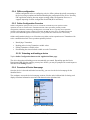
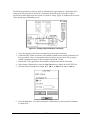
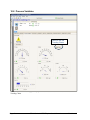
1
ST 800 Series HART/DE Option User’s Manual 34-ST-25-38 Revision 1.0 October, 2012 Honeywell Process Solutions Page ii ST 800 Series HART/DE Option User’s Manual Revision 1.0 Copyrights, Notices and Trademarks © Copyright 2012 by Honeywell, Inc. October, 2012 While the information in this document is presented in good faith and believed to be accurate, Honeywell disclaims any implied warranties of merchantability and fitness for a particular purpose and makes no express warranties except as may be stated in the written agreement with and for its customers. In no event is Honeywell liable to anyone for any indirect, special, or consequential damages. The information and specifications in this document are subject to change without notice. Honeywell, TDC 3000, SFC, SmartLine, PlantScape, Experion PKS, and TotalPlant are registered trademarks of Honeywell International Inc. Other brand or product names and service marks are the property of their respective owners. Honeywell Process Solutions 1860 Rose Garden Lane Phoenix, AZ 85027 Revision 1.0 ST 800 Series HART/DE Option User’s Manual Page iii About This Manual This manual provides the details of programming Honeywell ST 800 SmartLine Pressure Transmitters for applications involving HART versions 5, 6, and 7 and Honeywell’s Digitally Enhanced (DE) communication protocols. For installation, wiring, and maintenance information refer to the ST 800 SmartLine Pressure Transmitter User Manual, document number 34-ST-25-35. The configuration of your Transmitter depends on the mode of operation and the options selected for it with respect to operating controls, displays and mechanical installation. Details for operations involving the Honeywell Multi-Communication (MC) Tookit (MCT202) are provided only to the extent necessary to accomplish the tasks-at-hand. Refer to the associated MCT202 User Manual for complete details. The “Reference” section in the front matter of this manual lists document titles and numbers. The ST 800 SmartLine Pressure transmitter can be digitally integrated with one of two systems: • • Experion PKS: you will need to supplement the information in this document with the data and procedures in the Experion Knowledge Builder. Honeywell’s TotalPlant Solutions (TPS): you will need to supplement the information in this document with the data in the PM/APM SmartLine Transmitter Integration Manual, which is supplied with the TDC 3000 book set. (TPS is the evolution of the TDC 3000). Release Information ST 800 Series HART/DE Option User Manual, Document # 34-ST-25-38, Rev. 1.0, October, 2012 References The following list identifies publications that may contain information relevant to the information in this document. ST 800 SmartLine Pressure Transmitter Quick Start Installation Guide, Document # 34-ST-25-36 ST 800 SmartLine Pressure Transmitter with HART Communications Options Safety Manual, 34-ST-25-37 ST 800 SmartLine Pressure Transmitter User Manual, Document # 34-ST-25-35 ST 800 FF Transmitter with FOUNDATION Fieldbus Option Installation & Device Reference Guide, Document # 34-ST-25-39 ST 800 Function Blocks Reference Manual, Document # 34-ST-25-42 MC Tookit User Manual, Document # 34-ST-25-20 PM/APM SmartLine Transmitter Integration Manual, Document # PM 12-410 ST 800 Series Pressure, Analog, HART and DE Communications form, Honeywell drawing 50049892 Smart Field Communicator Model STS 103 Operating Guide, Document # 34-ST-11-14 Technical Bulletin, Communicating with Honeywell™ ST3000/STT3000 Smart Transmitters, Document #TB-960704B MC Toolkit Modem Code Download Instruction Manual, Document # 34-ST-25-33 Page iv ST 800 Series HART/DE Option User’s Manual Revision 1.0 Patent Notice The Honeywell ST 800 SmartLine Pressure Transmitter family is covered by one or more of the following U. S. Patents: 5,485,753; 5,811,690; 6,041,659; 6,055,633; 7,786,878; 8,073,098; and other patents pending. Support and Contact Information For Europe, Asia Pacific, North and South America contact details, refer to the appropriate Honeywell Solution Support web site: Honeywell Corporate www.honeywellprocess.com Honeywell Process Solutions www.honeywellprocess.com/pressue-transmitters/ Training Classes http://www.automationccollege.com Telephone and Email Contacts Area United States and Canada Global Email Support Revision 1.0 Organization Phone Number Honeywell Inc. 1-800-343-0228 Customer Service 1-800-423-9883 Global Technical Support Honeywell Process Solutions [email protected] ST 800 Series HART/DE Option User’s Manual Page v Contents 1 ST 800 Physical and Functional Characteristics ............................................................................ 1 1.1 Overview ................................................................................................................................ 1 1.2 Features and Options.............................................................................................................. 1 1.2.1 Physical Characteristics ................................................................................................. 2 1.2.2 Functional Characteristics .............................................................................................. 3 1.3 Series, Model and Number..................................................................................................... 3 1.4 Safety Certification Information ............................................................................................ 3 1.5 Transmitter Adjustments ........................................................................................................ 4 1.6 Local Display Options ........................................................................................................... 4 1.7 Optional 3-Button Assembly ................................................................................................. 5 2 Communication Modes .................................................................................................................. 6 2.1 Overview ................................................................................................................................ 6 2.2 Digitally Enhanced (DE) Mode Communication ................................................................... 6 2.3 HART Mode Communication ................................................................................................ 7 3 Configuration Tools and Interfaces................................................................................................ 8 3.1 Overview ................................................................................................................................ 8 3.2 Pre-requisites.......................................................................................................................... 8 3.3 Application Design, Installation, Startup, and Operation ...................................................... 8 3.3.1 Organization ................................................................................................................... 8 3.4 MC Toolkit Participation ....................................................................................................... 9 3.4.1 MC Toolkit Software Applications ................................................................................ 9 3.4.2 Configuration Databases ................................................................................................ 9 3.4.3 Configuration ................................................................................................................. 9 3.4.4 MC Toolkit–Transmitter Electrical/Signal Connections................................................ 9 4 DE Transmitter Configuration ..................................................................................................... 11 4.1 Configuration Personnel Requirements ............................................................................... 11 4.2 MC Toolkit Software Application Overview ....................................................................... 11 4.3 DE Transmitter Online Configuration ................................................................................. 12 4.3.1 Uploading a Transmitter Configuration ....................................................................... 12 4.3.2 Device Information Configuration ............................................................................... 14 4.3.3 General Configuration Parameters ............................................................................... 15 4.3.4 DE-Specific Configuration Parameters ........................................................................ 16 4.3.5 Transmitter Display Configuration .............................................................................. 18 4.3.6 Monitor Status Configuration ...................................................................................... 19 4.3.7 Saving the Configuration to File .................................................................................. 20 4.3.8 DE Online Configuration Summary............................................................................. 21 4.4 DE Transmitter Offline Configuration ................................................................................. 21 4.4.1 Overview ...................................................................................................................... 21 4.4.2 DE Offline File Management ....................................................................................... 21 4.4.3 Save to a File ................................................................................................................ 22 4.4.4 Downloading in DE Offline Mode............................................................................... 22 4.4.5 DE Offline Parameterization. ....................................................................................... 22 Page vi ST 800 Series HART/DE Option User’s Manual Revision 1.0 5 HART Transmitter Configuration ................................................................................................ 23 5.1 Overview .............................................................................................................................. 23 5.1.1 Personnel Requirements ............................................................................................... 23 5.2 Overview of FDC Homepage ............................................................................................... 24 5.2.1 Settings ......................................................................................................................... 25 5.2.2 Manage DDs ................................................................................................................. 26 5.2.3 Online configuration ..................................................................................................... 27 5.2.4 Offline configuration .................................................................................................... 28 5.2.5 Online Configuration Overview ................................................................................... 28 5.2.6 Overview of Device Homepage ................................................................................... 28 5.2.7 Tabs on the Device Home page .................................................................................... 29 5.2.8 Using FDC for various device operations .................................................................... 31 5.2.9 Device Configuration and Parameter Descriptions ...................................................... 33 5.2.10 Procedure to Enter the Transmitter Tag ....................................................................... 45 5.2.11 Selecting the Process Variable (PV) Unit of Pressure Measurement ........................... 45 5.2.12 Setting PV URV, and LRV Range Values ................................................................... 46 5.2.13 Setting Range Values for Applied Pressure ................................................................. 46 5.2.14 Saving device history ................................................................................................... 47 5.2.15 Exporting device history records to FDM .................................................................... 48 5.2.16 Exporting device history records to Documint ............................................................. 49 5.2.17 Custom Views .............................................................................................................. 49 5.2.18 Offline Configuration ................................................................................................... 51 6 DE Calibration .............................................................................................................................. 54 6.1 Overview .............................................................................................................................. 54 6.2 Calibration Recommendations ............................................................................................. 54 6.3 Test Equipment Required for Calibration ............................................................................ 54 6.4 Analog Output Signal Calibration ........................................................................................ 54 6.5 Calibrating Range Using the MC Toolkit............................................................................. 56 6.6 Conditions for Input Calibration .......................................................................................... 56 6.7 Input Calibration Procedures Description ............................................................................ 56 6.8 Input Calibration Procedure ................................................................................................. 57 6.8.1 Correct the Input at Zero .............................................................................................. 57 6.8.2 Correct Input at the Lower Range Value (LRV) .......................................................... 59 6.8.3 Correct Input at URV ................................................................................................... 60 6.9 DE Output Calibration .......................................................................................................... 61 6.9.1 Output Calibration Preparation ..................................................................................... 61 6.10 Manually Setting the Process Variable Range ..................................................................... 63 6.11 Procedure to Reset Calibration ............................................................................................. 66 7 HART Calibration ........................................................................................................................ 69 7.1 About This Section ............................................................................................................... 69 7.1.1 About Calibration ......................................................................................................... 69 7.1.2 Equipment Required ..................................................................................................... 69 7.2 Analog Output Signal Calibration ........................................................................................ 70 7.3 Calibrating Range ................................................................................................................. 71 7.3.1 Correcting the Lower Range Value (LRV) .................................................................. 71 7.3.2 Correcting the Upper Range Value (URV) .................................................................. 71 7.3.3 Resetting Calibration .................................................................................................... 72 7.3.4 Calibration Records ...................................................................................................... 73 Revision 1.0 ST 800 Series HART/DE Option User’s Manual Page vii 8 HART Advanced Diagnostics...................................................................................................... 74 8.1 About This Section .............................................................................................................. 74 8.2 Advanced Diagnostics.......................................................................................................... 74 8.2.1 Install Date ................................................................................................................... 74 8.2.2 PV Tracking Diagnostics ............................................................................................. 75 8.2.3 SV Tracking ................................................................................................................. 77 8.2.4 TV Tracking Diagnostics ............................................................................................. 78 8.2.5 ET Tracking Diagnostics ............................................................................................. 78 8.2.6 % Stress Life ................................................................................................................ 80 8.2.7 % Service Life.............................................................................................................. 80 8.2.8 Operating Voltage Diagnostics .................................................................................... 80 8.2.9 AVDD Tracking Diagnostics ....................................................................................... 81 8.2.10 Sensor CPU Temperature Tracking Diagnostics ......................................................... 81 8.2.11 Power Up Diagnostics .................................................................................................. 82 9 Troubleshooting and Maintenance ............................................................................................... 83 9.1 HART Diagnostic Messages ................................................................................................ 83 9.2 HART Diagnostic Details .................................................................................................... 83 9.3 DE Diagnostic Messages ..................................................................................................... 87 10 Using DTMs............................................................................................................................. 90 10.1 Introduction .......................................................................................................................... 90 10.2 Components ......................................................................................................................... 90 10.3 Downloads ........................................................................................................................... 90 10.4 Procedure to Install and Run the DTM ................................................................................ 90 10.5 ST 800 Online Parameterization .......................................................................................... 91 10.5.1 Device Health: ............................................................................................................. 92 10.5.2 Device Icon / Honeywell Logo: ................................................................................... 92 10.5.3 Process Variables: ........................................................................................................ 92 10.5.4 Shortcuts: ..................................................................................................................... 92 10.6 Basic Setup Page .................................................................................................................. 93 10.6.1 Pressure Transfer Fn: ................................................................................................... 93 10.6.2 Low Flow Cutoff Mode: .............................................................................................. 93 10.6.3 Device Information ...................................................................................................... 94 10.6.4 Model Number: ............................................................................................................ 94 10.6.5 Device Assembly: ........................................................................................................ 94 10.6.6 System Setup:............................................................................................................... 94 10.7 Calibration Page ................................................................................................................... 94 10.7.1 Calibration Methods..................................................................................................... 95 10.7.2 Calibration Records...................................................................................................... 95 10.8 Process Variables ................................................................................................................. 96 10.9 Trend Charts......................................................................................................................... 97 10.10 Device Status ................................................................................................................... 98 10.11 Critical and Non-Critical Help Display............................................................................ 99 10.12 Diagnostics:.................................................................................................................... 100 10.13 Services .......................................................................................................................... 101 10.14 Detailed Setup ................................................................................................................ 102 10.15 Meterbody Selection ...................................................................................................... 103 10.16 Display Setup ................................................................................................................. 103 10.17 Read Screen Info: ........................................................................................................... 104 Page viii ST 800 Series HART/DE Option User’s Manual Revision 1.0 10.18 Screen Configuration: ..................................................................................................... 104 10.19 Common setup:............................................................................................................... 104 10.20 Review ............................................................................................................................ 104 10.21 ST 800 Offline Parameterization .................................................................................... 105 11 HART DD binary file format compatibility matrix ................................................................ 106 Glossary .............................................................................................................................................. 107 Sales and Service .................................................................................................................................... 1 Revision 1.0 ST 800 Series HART/DE Option User’s Manual Page ix List of Figures Figure 1 – ST 800 Major Assemblies ............................................................................................... 2 Figure 2 – Electronics Housing Components.................................................................................... 2 Figure 3 –Typical Atmospheric or Gauge Pressure Transmitter Name Plate Information ............... 3 Figure 4 – DE Mode Value Scaling .................................................................................................. 6 Figure 5 – HART Point-to-Point and Multi-drop Value Scaling ...................................................... 7 Figure 6 – MC Toolkit-Transmitter Electrical/Signal Connections ................................................ 10 Figure 7 – Differential Pressure Square Root Conformity Curve ................................................... 17 Figure 8 – FDC Homepage ............................................................................................................. 24 Figure 9 – Device Homepage.......................................................................................................... 28 Figure 10 – Analog Output Calibration Test Setup......................................................................... 55 Figure 11 – Input Calibration Connections ..................................................................................... 57 Figure 12 – Output Calibration Test Connections .......................................................................... 61 Figure 13 – DE Analog Mode Scaling and Test Connections ........................................................ 61 Figure 14 – Setup to Manually Set the PV LRV and URV............................................................. 63 Figure 15 – Typical Calibration Test Setup .................................................................................... 66 List of Tables Table 1 – Features and Options......................................................................................................... 1 Table 2 – Available Display Characteristics ..................................................................................... 4 Table 3 – User Manual Related Topics ............................................................................................. 8 Table 4 – Device Information Parameters ...................................................................................... 14 Table 5 – General Configuration Parameters .................................................................................. 15 Table 6 – DE Configuration Parameters ......................................................................................... 16 Table 7 – Local Display Configuration Parameters ........................................................................ 18 Table 8 – Monitor Parameters ......................................................................................................... 19 Table 9 - FDC homepage elements ................................................................................................. 24 Table 10 - Device health status ....................................................................................................... 29 Table 11 – HART Transmitter Parameters ..................................................................................... 33 Table 12 – Tamper Reporting Logic Implementation with Write Protect ...................................... 44 Table 13 – Calibration Records....................................................................................................... 73 Table 14 – Viewing Advanced Diagnostics .................................................................................... 74 Table 15 – Maximum PV Tracking ................................................................................................ 76 Table 16 – Minimum PV Tracking ................................................................................................. 76 Table 17 – Maximum SV Tracking ................................................................................................ 77 Table 18 – Minimum SV Tracking ................................................................................................. 77 Table 19 – TV Tracking Diagnostics .............................................................................................. 78 Table 20 – Maximum ET Diagnostics ............................................................................................ 78 Table 21 – Minimum ET Diagnostics ............................................................................................. 79 Table 22 – Operating Voltage Diagnostics ..................................................................................... 80 Table 23 – Maximum and Minimum AVDD Tracking .................................................................. 81 Table 24 – Maximum Sensor CPU Temperature Tracking............................................................. 81 Table 25 – Minimum Sensor CPU Temperature Tracking ............................................................. 81 Table 26 – Power Up Diagnostics ................................................................................................... 82 Table 27 – HART Diagnostic Messages ......................................................................................... 83 Table 28 – HART Critical and Non-Critical Diagnostic Details .................................................... 83 Table 29 – DE Diagnostics ............................................................................................................. 87 Page x ST 800 Series HART/DE Option User’s Manual Revision 1.0 1 ST 800 Physical and Functional Characteristics 1.1 Overview This section is an introduction to the physical and functional characteristics of Honeywell’s family of ST 800 SmartLine Pressure Transmitters. 1.2 Features and Options The ST 800 SmartLine Pressure Transmitter is available in a variety of models for measuring Differential Pressure (DP), Gauge Pressure (GP), and Absolute Pressure (AP). Table 1 lists the protocols, human interface (HMI), materials, approvals, and mounting bracket options for the ST 800. Table 1 – Features and Options Feature/Option Standard/Available Options Communication Protocols HART, Digitally Enhanced (DE), Fieldbus Human-Machine Interface (HMI) Options (Basic and Advanced Display) Basic and Advanced Digital Display Three-button programming (optional) Basic display language: English only Calibration Advanced display languages: English, German, French, Spanish, and Russian Single Approvals (See Appendix C for details.) ATEX, CSA, FM, IECx, NEPSI Mounting Brackets Angle/flat carbon steel/304 stainless steel, Marine 304 stainless steel Experion Integration Tools Revision 1.0 ST 800 Series HART/DE Option User’s Manual Page 1 1.2.1 Physical Characteristics As shown in Figure 1, the ST 800 is packaged in two major assemblies: the Electronics Housing and the Meter Body. The elements in the Electronic Housing respond to setup commands and execute the software and protocol for the different pressure measurement types. Figure 2 shows the assemblies in the Electronics Housing with available options. The Meter Body provides connection to a process system. Several physical interface configurations are available, as determined by the mounting and mechanical connections. Refer to the ST 800 SmartLine User’s Manual, document number 34-ST-25-35 for installation and wiring details. Figure 1 – ST 800 Major Assemblies Figure 2 – Electronics Housing Components Page 2 ST 800 Series HART/DE Option User’s Manual Revision 1.0 1.2.2 Functional Characteristics Functionally, the Transmitter measures process pressure and outputs a signal proportional to the measured process variable (PV). Available output communication protocols include analog 4 to 20 mA, Honeywell Digitally Enhanced (DE) protocol, HART, and FOUNDATION Fieldbus. An optional 3-button assembly is available to set up and make adjustments to the Transmitter. In addition, a Honeywell Multi-Communication (MC) Toolkit (not supplied with the Transmitter) can facilitate setup and adjustment procedures. Certain adjustments can be made through an Experion Station or a Universal Station if the Transmitter is digitally integrated with Honeywell’s Experion or TPS/TDC 3000 control system. 1.3 Series, Model and Number The Transmitter nameplate mounted on the top of the Electronics Housing (see Figure 2) lists the model number, physical configuration, electronics options, accessories, certifications, and manufacturing specialties. Figure 3 is an example of a typical Differential Pressure (DP) or Gauge Pressure (GP) or Atmospheric Pressure (AP) Transmitter name plate. The model number format consists of a Key Number with several table selections. The Differential Pressure (DP), Absolute Pressure (AP), and Gauge Pressure (GP) name plates are essentially the same. However, the DP provides one additional entry (7 vs. 6 characters) in the Meter Body Selections (Table I) to accommodate the static pressure rating. Figure 3 –Typical Atmospheric or Gauge Pressure Transmitter Name Plate Information You can readily identify the series and basic Transmitter type from the third and fourth digits in the key number. The letter in the third digit represents one of these basic transmitter types: • • A = Absolute Pressure G = Gauge Pressure • • D = Differential Pressure R = Remote Seals • F = Flange Mounted For a complete selection breakdown, refer to the appropriate Specification and Model Selection Guide provided as a separate document. 1.4 Safety Certification Information An “approvals” name plate is located on the bottom of the Electronics Assembly; see Figure 1 for exact location. The approvals name plate contains information and service marks that disclose the Transmitter compliance information. Refer to Appendix C of the ST 800 SmartLine Transmitters User’s Manual, document number 34-ST-25-35 for details. Revision 1.0 ST 800 Series HART/DE Option User’s Manual Page 3 1.5 Transmitter Adjustments Zero and Span adjustments are possible in new generation ST 800 SmartLine Pressure Transmitters by using the optional three-button assembly located at the top of the Electronic Housing (see Figure 2). However, certain capabilities are limited in the following configurations: • Without a display – Zero and Span setting only for HART and DE devices. • With a display – Complete Transmitter configuration is possible for HART & DE devices. You can also use the Honeywell MCT202 Configuration Tool to make any adjustments to an ST 800 Transmitter. The MCT202 tool has two applications; MC Toolkit and FDC. Using the MC Toolkit application you can adjust the ST 800 DE model configuration. Using the Field Device Configurator (FDC) application, you can adjust the ST 800 HART model configuration. Alternately, you can use the Honeywell SmartLine Configuration Tool, SCT 3000, for configuring DE models. Certain adjustments can also be made through the Experion or Universal Station if the Transmitter is digitally integrated with a Honeywell Experion or TPS system. ST 800 HART models can be configured using Honeywell tools such as Experion in conjunction with FDM, using DTMs running in FDM or Pactware, or Emerson 375 or 475. 1.6 Local Display Options The ST 800 Pressure Transmitter offers two display options: Basic and Advanced; see Table 2. Table 2 – Available Display Characteristics Basic Display • Suitable for basic process needs • 360o rotation in 90o Increments • 2 lines, 16 characters • Standard engineering units • Diagnostic messaging • Square root output indication • Supports optional 3-Button configuration and calibration • • 360o rotation in 90o increments Three (3) configurable screen formats: o Large process variable (PV) o PV with bar graph o PV with trend (1-24 hours, configurable) Eight (8) screens 3-30 seconds configurable rotation timing Standard and custom engineering units Diagnostic alerts and diagnostic messaging Multiple language support: o English, French, German, Spanish, Russian Square root output indication Supports optional 3-Button configuration and calibration Supports transmitter messaging and maintenance mode indication • Advanced Display • • • • • • Page 4 ST 800 Series HART/DE Option User’s Manual Revision 1.0 1.7 Optional 3-Button Assembly The optional 3-button assembly provides the following features: • • • • • Opportunity for immediate reaction with minimal disruptions Improved maintenance time Potential savings on hand-held units Suitable for all environments: hermetically sealed for long life in harsh environments Suitable for use in all electrical classifications (flameproof, dustproof, and intrinsically safe) The 3-button assembly is externally accessible and provides the following capabilities: • • Menu-driven configuration with optional display: o Using increment, decrement & enter keys o A comprehensive on screen menu guides the way o Configure the transmitter o Configure the display o Set zero and span Zero and span settings without optional display Revision 1.0 ST 800 Series HART/DE Option User’s Manual Page 5 2 Communication Modes 2.1 Overview The ST 800 SmartLine Pressure Transmitter can be configured for operation with Honeywell’s Digitally Enhanced (DE) communication protocol, HART version 7, and Fieldbus communication. This manual addresses the processes to configure and calibrate a Transmitter for DE and HART communication. Refer to the ST 800 FF Transmitter with FOUNDATION Fieldbus Option Installation & Device Reference Guide, document number 34-ST-25-39 for Fieldbus details. 2.2 Digitally Enhanced (DE) Mode Communication Although it is unnecessary to put a control loop in manual mode before communicating with a Transmitter operating in DE mode, caution is required if there is potential for error in identifying the operating mode. In DE mode, the PV is available for monitoring and control purposes; and the meter body temperature (secondary variable) is available for monitoring purposes only. Much of the operation in the Digitally Enhanced (DE) mode is similar to that of analog operation. The essential characteristics of DE mode operation are shown in Figure 4. Figure 4 – DE Mode Value Scaling As indicated at the right of Figure 4, output values of process variables, as well as communications are transferred to a receiving device digitally. The digital coding is Honeywell proprietary, which requires the use of DE-capable Honeywell control equipment. The use of DE mode offers several advantages: • • • • Page 6 Process Safety. Unlike analog mode, communications devices do not bump the PV value. Accuracy: requires less maintenance. Digital communication: Relatively immune to small variations in circuit resistance or supply voltage. Facilitates Maintenance Tasks: Honeywell control systems include operating displays that enable direct communication with transmitters operating in DE mode. ST 800 Series HART/DE Option User’s Manual Revision 1.0 2.3 HART Mode Communication When using MCT202,before connecting to a HART transmitter, verify that the FDC application is used and not the MC Toolkit application. When you use the MC Toolkit application, the MCT202 is set for DE communications, where the current amplitude can bump process variables in either point-to-point or in the multi-drop mode in HART. • Transmitters with HART capability have features that vary among manufacturers and with the characteristics of specific devices. The FDC software application executing on the MCT202 supports the HART Universal, Common Practice and Device Specific Commands which are implemented in the Honeywell Transmitters. As indicated in Figure 5, the output of a Transmitter configured for HART protocol includes two primary modes: Figure 5 – HART Point-to-Point and Multi-drop Value Scaling • • Point-to-Point Mode, in which one Transmitter is connected via a two-conductor, 4-20 mA current loop to one receiver. Multi-Drop Mode, in which several Transmitters are connected through a two-conductor network to a multiplexed receiver device. In point-to-point mode, the value of the primary Process Variable (PV) is represented by a 4-20 mA current loop, almost identical to that of a Transmitter operating in analog mode. In this case, however, the analog signal is modulated by Frequency Shift Keying (FSK), using frequencies and current amplitude that do not affect analog sensing at the receiver. The accuracy of the analog level must be precisely controlled for accurate sensing. HART communication will not bump process variables. In multi-drop mode, up to 16 transmitters in HART 5 (addresses 0-15) and up to 64 transmitters in HART6/7 (addresses 0-63) can exist on the two-conductor network. Revision 1.0 ST 800 Series HART/DE Option User’s Manual Page 7 3 Configuration Tools and Interfaces 3.1 Overview This section describes the tools and interfaces involved in configuring a new ST 800 SmartLine Pressure Transmitter for HART or DE communication operation. The information in this section also applies to adjusting the configuration of a Transmitter that has been in operation and updating one that is currently in operation. 3.2 Pre-requisites The information and procedures in this manual are based on the assumption that personnel performing configuration and calibration tasks are fully qualified and knowledgeable in the use of the Honeywell MC Toolkit or MCT202. The name MC Toolkit or Toolkit and MCT202 are used interchangeably as MCT202 is the model name for the Honeywell MC Toolkit product. Furthermore, we assume that the reader is intimately familiar with the ST 800 family of SmartLine Pressure Transmitters and thoroughly experienced in the type of process application targeted for Transmitter deployment. Therefore, detailed procedures are supplied only in so far as necessary to ensure satisfactory completion of configuration tasks. 3.3 Application Design, Installation, Startup, and Operation The ST 800 SmartLine Pressure Transmitters User’s Manual, document number 34-ST-25-35, provides the details for application design, installation, and startup; see Table 3 for topics. Table 3 – User Manual Related Topics ST 800 SmartLine Pressure Transmitters Users Manual Section 2. Application Design Safety and accuracy Diagnostics messages Design consideration Section 3. Installation and Startup Section 4. Operation Site evaluation Toolkit issues Display installation concerns Transmitter mounting & zero-correction Piping & wiring Startup tasks and procedures Three-button option Failsafe direction setup Monitoring displays 3.3.1 Organization This information in this section is arranged in the following sequence: • • Page 8 MC Toolkit participation in ST 800 Transmitter Setup and Configuration: o Physical circuit connections o Application components o Configuration for Analog, DE, and HART operation ST 800 Transmitter o Basic and advanced displays o Health indications o Ability to be configured and operate in a process system ST 800 Series HART/DE Option User’s Manual Revision 1.0 3.4 MC Toolkit Participation Before using the MC Toolkit, be sure that you are aware of the potential consequences of each procedure, and that you use appropriate safeguards to avoid possible problems. For example, if the Transmitter is an element in a control loop, the loop needs to be put in manual mode, and alarms and interlocks (i.e., trips) need to be disabled, as appropriate, before starting a procedure. 3.4.1 MC Toolkit Software Applications The MC Toolkit has two software applications to work with ST 800 SmartLine Pressure Transmitters: • • Field Device Configurator (FDC). This application is used for configuring, calibrating, monitoring, and diagnosing HART devices. FDC conforms to the IEC 61804-3 EDDL (Electronic Data Description Language) standard specification. The FDC application is an open solution that supports devices with a registered device description (DD) file compatible with HART Communication Foundation (HCF) requirements. MC Toolkit. This application is used for configuring, calibrating, monitoring, and diagnosing Honeywell Digitally Enhanced (DE) devices. Details for working with the MC Toolkit are provided in the MC Tookit User Manual, document # 34-ST-25-20. In subsequent sections of this manual, explicit operating instructions are provided only in so far as necessary to complete required tasks and procedures. 3.4.2 Configuration Databases The MC Toolkit is used to establish and/or change selected operating parameters in a Transmitter database. 3.4.3 Configuration Configuration can be accomplished both online and offline with the Transmitter powered up and connected to the MC Toolkit. Online configuration immediately changes the Transmitter operating parameters. For offline configuration, Transmitter operating characteristics are entered into Toolkit memory for subsequent downloading to a Transmitter. When you set up or configure a Transmitter, it can take up to 30 seconds for the value to be stored in it. If you change a value and Transmitter power is interrupted before the change is copied to nonvolatile memory, the changed value will not be moved to nonvolatile memory. 3.4.4 MC Toolkit–Transmitter Electrical/Signal Connections Figure 6 displays how to connect the MC Toolkit directly to the terminals of a HART or DE Transmitter (top), and a HART-only Transmitter (bottom). Revision 1.0 ST 800 Series HART/DE Option User’s Manual Page 9 Figure 6 – MC Toolkit-Transmitter Electrical/Signal Connections Page 10 ST 800 Series HART/DE Option User’s Manual Revision 1.0 4 DE Transmitter Configuration 4.1 Configuration Personnel Requirements The configuration processes in this section reflect the assumption that you will use the Honeywell MC Toolkit Configuration Tool to configure an ST 800 SmartLine Pressure Transmitter. The MC Toolkit application is used to configure Honeywell ST 3000 Pressure Transmitter, STT 3000 Smart Temperature Transmitters, as well as the ST 800 SmartLine Pressure Transmitter. Throughout, the term Transmitter means the ST 800 SmartLine Pressure Transmitter. The other tools that support DE Transmitter configuration are the SmartLine Configuration Toolkit (SCT 3000), Experion PKS, and Smart Field Communicator (SFC). 4.2 MC Toolkit Software Application Overview Each new ST 800 SmartLine Pressure Transmitter is shipped from the factory with a basic configuration installed. This basic configuration must be edited or revised to meet the requirements of your process system. The MC Toolkit application supports both online and offline configuration. • Online operation allows you to establish communication with a DE Transmitter for the following tasks: o o o o o • Upload a Transmitter database. Configure Transmitter parameters. Calibrate a Transmitter. Execute diagnostics. Save a configuration to a file. Offline operation allows you to select a basic template, edit the parameters and download to a Transmitter after establishing communication with it. Parameter updates can also be saved in a file without actually downloading them to a Transmitter. Specific operating details for the MC Toolkit displays are provided in Section 3.5, “MC Toolkit Application Software Display Conventions,” of the MC Toolkit User Manual, (document number 34ST-25-20) for the following: • • • • • • Navigation The MC Toolkit Menu Bar File Menu Modem Menu Help Menu Data Entry and Display Revision 1.0 ST 800 Series HART/DE Option User’s Manual Page 11 4.3 DE Transmitter Online Configuration Online configuration consists of establishing communication between the MC Toolkit and a Transmitter configured for DE communication. Each Transmitter has a configured database, whether new from the factory, a spare, or one to be reconfigured. In any case, the MC Toolkit application is used to upload the existing configuration from the Transmitter for review and editing. 4.3.1 Uploading a Transmitter Configuration 1. Connect a DE Transmitter to the MC Toolkit. Be sure that both devices have power applied. 2. Start the MC Toolkit application by selecting Start / MC Toolkit on the MC Toolkit / MCT202. The MC TOOLKIT Home page will be displayed. 3. Select the Online button, and establish communication between the Toolkit and the Transmitter. 4. When the warning message for connecting to a DE device appears, select OK. 5. Process the three warning pop-ups as appropriate, and then select OK in the Put loop in Manual… pop-up. The QUICK MONITOR box will be displayed. Page 12 ST 800 Series HART/DE Option User’s Manual Revision 1.0 6. Select Upload. A progress bar will be displayed on the QUICK MONITOR box, and when the upload is complete, the DE MAIN MENU will be displayed. A confirmation request message will be displayed if you select <Back for a Transmitter that was previously set to Output Mode during calibration, and was not subsequently cleared. If you confirm the message (Yes answer), the display will exit the DE MAIN MENU. Revision 1.0 ST 800 Series HART/DE Option User’s Manual Page 13 4.3.2 Device Information Configuration In this and subsequent procedures, the notations R for read only and R/W for read/write are used to indicate if a parameter can be edited. 1. On the DE MAIN MENU, select Device Info. The DEVICE INFO box will be displayed. 2. Configure device information according to Table 4. Table 4 – Device Information Parameters Parameter Read (R) or Read/Write (R/W) Configuration Details Tag ID R/W User ID up to 8 alphanumeric characters. Type R Manufacturer’s device type identifier Firmware Version R Manufacturer’s firmware version identifier PROM ID Number R PROM ID Number Scratch Pad 3. Page 14 R/W Up to 32 alphanumeric characters Select the Back button to go back to the DE MAIN MENU. ST 800 Series HART/DE Option User’s Manual Revision 1.0 4.3.3 General Configuration Parameters Select the General button on the DEVICE MAIN MENU page, and configure parameters according to Table 5. Parameter Table 5 – General Configuration Parameters Read (R) or Configuration Details Read/Write (R/W) PV Type R/W Dual Range Smart Transmitter Digital Communications (STDC) or Single Range or Single Range with secondary variable (SV). Communication Mode R/W Analog, DE 4-byte, or DE 6-byte FS Direction R Failsafe (FS) direction: upscale or downscale, switch selectable on the electronics module. See the ST 800 SmartLine Transmitter User Manual for details. Select the Back button to go back to the DE MAIN MENU. Revision 1.0 ST 800 Series HART/DE Option User’s Manual Page 15 4.3.4 DE-Specific Configuration Parameters Select the Configure button, and configure parameters according to Table 6. Table 6 – DE Configuration Parameters Parameter Read (R) or Read/Write (R/W) Configuration Details LRL R Lower Range Limit, Floating Point URL R Upper Range Limit, Floating Point LRV R/W Lower Range Value, Floating Point URV R/W Upper Range Value, Floating Point PV Units R/W Process Variable Units: scaling value selection; default = inches H20@39oF SV Units R/W Secondary Variable scaling units: oC or oF Sensor Type R R/W Damping R Span Conformity R/W Sensor type used in the Transmitter Select digital noise reduction; (see note below) Process Range: URV – LRV, Floating Point Conformity: for the output calculation. Linear (pressure) or Square Root (flow); (see note below) Select the Back button to go back to the DE MAIN MENU. 4.3.4.1 Notes on Damping (Digital Noise Reduction) You can adjust the damping time to reduce output noise. By way of suggestion, set damping to the smallest value reasonable for your process. The electrical noise effect on the output signal is partially related to the turndown ratio of the Transmitter. As the turndown ratio increases, the peak-to-peak noise on the output signal increases. You can use the following formula to find the turndown ratio using the range information for your Transmitter. Turndown Ration Upper Range Limit Upper Range Value Lower Range Value Note that ST 800 Transmitters are specified with a minimum of 100:1 turndown capability. Page 16 ST 800 Series HART/DE Option User’s Manual Revision 1.0 4.3.4.2 Notes on Conformity You can select the Transmitter output to represent a straight linear or a square root calculation for flow measurement applications with a differential pressure (DP) unit. For a differential pressure (DP) Transmitter, measuring the pressure drop across a primary element, the flow rate is directly proportional to the square root of the pressure drop. The Transmitter output automatically converts to percent-of-flow when its output conformity is configured as square root. You can use the following formulas to manually calculate the percent of flow for comparison purposes: ∆P S Where ΔP Span %P Therefore: 100 %P = Differential pressure input in engineering units = Transmitter measurement span (URV- LRV) = Pressure in percent of span %P 100 % Flow Also, you can use the following formula to determine the corresponding current output in Milliamperes DC. (% Flow X 16) + 4 = mA DC Output To avoid unstable output at readings near zero, the ST 800 Transmitter automatically drops square root conformity and changes to linear conformity for low differential pressure readings. As shown in Figure 7, the dropout point is between 0.4% and 0.5% of differential pressure, depending on direction . Figure 7 – Differential Pressure Square Root Conformity Curve Revision 1.0 ST 800 Series HART/DE Option User’s Manual Page 17 4.3.5 Transmitter Display Configuration From the DE MAIN MENU, select the Local Display button. The LOCAL DISPLAY box will be displayed. Select display parameters from the options listed in Table 7 Parameter Display Hardware Table 7 – Local Display Configuration Parameters Read (R) or Read/Write Configuration Details (R/W) Type of Transmitter Display: • Full Functional Display R • No Display installed Display Units R/W Engineering Units for this Display: %, inH2O@39oF mmHg@0oC psi, KPa MPa, mBar, Bar g/cm2, kg/cm2 mmH2O@4oC mHg@0oC mH2O@4oC GPM GPH Custom Custom Units Tag R/W 8 Characters Note that the Custom Units Tag is not sent to the Display. It will be displayed in the Tool. Flow EU Upper Value R/W Floating point (for square root configurations) Flow EU Lower Value R/W Floating point (for square root configurations) Select the Back button to go back to the DE MAIN MENU. Page 18 ST 800 Series HART/DE Option User’s Manual Revision 1.0 4.3.6 Monitor Status Configuration With the DE MAIN MENU displayed, select the Monitor button. The MONITOR box will be displayed. MONITOR status parameters are R (read only); lists the status parameters. Table 8 – Monitor Parameters Parameter Read (R) or Read/Write (R/W) Configuration Details Input R Sensor input in EU Output R Loop output as a percent of Span SV R Secondary Variable in SV EU Gross Status R Gross Transmitter Status. Select the Monitor menu Device Status button to display device status. Communication Status R Refer to the “Messages and Diagnostic Codes” section of the MCT202 Toolkit manual. Select the Back button to go back to the DE MAIN MENU. Revision 1.0 ST 800 Series HART/DE Option User’s Manual Page 19 4.3.7 Saving the Configuration to File 1. Display the DE MAIN MENU, and select the Save to File button. The File Dialog will be displayed. 2. Save the configuration as follows: a. Select Cancel to return to the DE MAIN MENU, and abort saving the configuration. b. Select Yes to add the configuration to the current working file, and return the display to the DE MAIN MENU. c. Select No to save to a different file; the Save As screen will be displayed. d. The default location and folder are set to SD Card and CFG_MCT. However, you can type in a new name for the file; the default name is New1. e. After entering the file name, select the Save button to display the DE MAIN MENU. Page 20 ST 800 Series HART/DE Option User’s Manual Revision 1.0 4.3.8 DE Online Configuration Summary This concludes the process of configuring an ST 800 DE transmitter online. For best operational results, calibrate the Transmitter according to Section 6, “Calibration” in this document. 4.4 DE Transmitter Offline Configuration 4.4.1 Overview This section summarizes the features, capabilities, and processes for configuring an ST 800 SmartLine Pressure Transmitter set for DE operation offline. Refer to the MC Tookit User Manual, 34-ST-25-20, section 5.6, “Offline Configuration” for complete procedural details. After starting the MC Toolkit application, selecting the Offline button provides access to the following configuration features: • • • DE Offline File Management – Open an XML file, select a saved configuration for the selected device and edit the parameters. Save to File – Save the parameters back to the file. Download – Download the current offline configuration to a device after establishing connection. The MC Tookit can process more than one device type or model. For the purposes of this section, the term device refers to the ST 800 SmartLine Pressure Transmitter, and/or one of its model variants. 4.4.2 DE Offline File Management Offline configuration allows you to select a basic template, edit its parameter content, and download it to a Transmitter after establishing communication. Parameter updates can also be saved in a file without actually downloading to a Transmitter. The MCT202 Toolkit is shipped with the two files: MCToolkit.xml andTEMPLMCT.xml: • • The MCToolkit.xml file consists of default configurations for all the supported DE devices. The available configurations can be updated and saved back to this file. The TEMPLMCT.XML is a template file. The contents of this template file cannot be edited; however, the template can be saved under a different file name. The contents of the newly named file can be edited. DE offline file management provides general, configuration, and parameter options. General options provide for communication serial port selection of COM1 through COM8. However, the current configuration of the Toolkit Pocket PC (PPC) provides only COM1; the other seven serial port designations are reserved for future expansion. Offline configuration options provide for confirmation before saving a changed configuration file. Denying confirmation results in having the changes discarded. In addition to file saving confirmation, DE offline file management provides access to three parameter sets for review and editing: • Parameter Set 1 consists of the description of Transmitter according to bus type, device type, serial and model number, and the manufacturer. Revision 1.0 ST 800 Series HART/DE Option User’s Manual Page 21 • • Parameter Set 2 permits entering/editing the values for the LRL, URL, LRV, URV, PV Units, Damping, SV Units, Line Filter frequency, Sensor Type, and the Conformity selection. Parameter Set 3 is oriented primarily to the Honeywell SmartLine Temperature Transmitter models for monitoring purposes. 4.4.3 Save to a File Saving to a file in offline mode will let you add an edited configuration to a working file. Alternately, if you decide not to save an edited configuration to the current file, you can select a new location and file name for it. The default location and folder for saving configurations are SD Card and CFG MCT. The default name of a new configuration is New1, which you can change for your needs. 4.4.4 Downloading in DE Offline Mode Downloading a file to a Transmitter from the Toolkit requires a communicating connection between the two units. Serial communication is established when you select DOWNLOAD to Device from the Toolkit Select Device menu. When the download completes, confirmation will be required to affirm that the configuration for the Transmitter is to be saved. 4.4.5 DE Offline Parameterization. A table in Section 6, “Offline Configuration,” of the MC Tookit User Manual, 34-ST-25-80 contains a list of the basic ST 800 SmartLine Pressure Transmitter parameters for DE operation. Page 22 ST 800 Series HART/DE Option User’s Manual Revision 1.0 5 HART Transmitter Configuration 5.1 Overview Each new ST 800 Pressure Transmitter configured for HART protocol is shipped from the factory with a basic configuration database installed. This basic configuration database must be edited or revised to meet the requirements of your process system. The process in this section assumes that you will use the Field Device Communicator (FDC) application for HART configuration tasks. The FDC application provides the facilities for the online and offline configuration of Transmitters operating with HART protocol Online configuration requires that the Transmitter and MC Toolkit are connected and communication between the two has been established. Online configuration provides a set of functions with which to perform various operations on a HART communication network through an active communication link. These operations primarily include configuration, calibration, monitoring, and diagnostics. Typically, these operations could be realized through various constructs exposed by the Device Description (DD) file. In addition, the FDC application provides some functions for convenient execution of these functions. Offline Configuration refers to configuring a device when the device is not physically present or communicating with the application. This process enables you to create and save a configuration for a device, even when the device is not there physically. Later when the device becomes available with live communication, the same configuration can be downloaded to the device. This feature enables you to save on device commissioning time and even helps you to replicate the configuration in multiplicity of devices with lesser efforts. Currently, FDC does not support creating offline configuration. However, it supports importing of offline configuration from FDM R310 or later versions. The configurations thus imported can be downloaded to the device from FDC. The following are the tasks that you need to perform for importing offline configuration in FDC application software and then downloading it to the device. • • • • Create offline configuration template in FDM Save the configuration in FDM in FDM format. Import the offline configuration in FDC Download the offline configuration to the device Note: For details on creating and using offline configuration, refer to section Offline configuration in FDM User’s Guide. 5.1.1 Personnel Requirements The information and procedures in this section are based on the assumption that the person accomplishing configuration tasks is fully qualified and knowledgeable on the use of the MC Toolkit and is intimately familiar with the ST 800 family of SmartLine Pressure Transmitters. Therefore, detailed procedures are supplied only in so far as necessary to ensure satisfactory configuration. The other HART configuration Tools are Honeywell Experion in conjunction with FDM, iDTMs running on FDM or Pactware, and Emerson 375/475. The organization of Device Configuration and Parameter Descriptions on page 33 is given in Table 11. Revision 1.0 ST 800 Series HART/DE Option User’s Manual Page 23 5.2 Overview of FDC Homepage The FDC homepage consists of links for Online Configuration, Offline Configuration, Manage DDs, and Settings. See below. Figure 8 – FDC Homepage lists the items that appear on the FDC homepage and its descriptions. Table 9 - FDC homepage elements Items Description Screen title. Tap to quit FDC. Tap to view the application information. Tap to navigate to Online Configuration screen. Tap to navigate to Offline configuration screen. Tap to navigate to Manage DDs screen. Tap to navigate to Settings screen. Tap to select the highlighted menu option. Tap to quit FDC. Note: To select a particular option in FDC you can either select the option and then tap Select or you can directly double-tap the option. Page 24 ST 800 Series HART/DE Option User’s Manual Revision 1.0 5.2.1 Settings Use this feature to customize FDC. You can customize FDC for device detection, DD selection, and other application settings. 5.2.1.1 Device Identification Use the following options to configure FDC to identify a device. • Using Poll Address − Use poll address 0 only: Use this to detect a device with the poll address as zero. − Find first poll address and use: Use this to detect a device with the first available poll address in the range of poll addresses that are available. − Use selected poll address: Use this to detect a device with a specific poll address in the range of zero to 63. − Use From: Use this to detect a device based on a range of poll addresses. • Using Device TAG: Use this to detect a device with a known HART tag. • Using Device LONG TAG: Use this to detect a device with a known HART long tag (applicable for devices with HART 6 or later Universal revisions). Note: If you choose the option Using Device TAG or Using Device LONG TAG, FDC prompts you to enter a device tag/long tag name during device detection. 5.2.1.3 DD selection Use the following options to configure FDC to select DD files when a DD with matching device revision is not available. - Use DD file of previous device revision: Use this option to automatically communicate using a DD file having device revision lower than that of the device. - Use generic DD file: Use this option to automatically communicate to the device using an appropriate generic DD file. - Always ask user: Use this option to always prompt you with a choice for communicating to the device either using the previous device revision or using a generic DD file. - Always Use Generic: Use this option to always communicate to the device using generic DD files even if a DD file with matching device revision as the device is present. Note: A generic DD file is a DD file that provides access and interface to the universal data and features of a HART device. 5.2.1.4 Other settings Low storage notification: Use this option to set a percentage value and to notify you with a warning message when the available storage card space is less than the percentage set. Application diagnostics: Use this option to enable or disable the logging infrastructure for application diagnostics. With this option enabled, FDC creates necessary log files for troubleshooting and diagnostics. These files are stored in SD Card\FDC folder. Note: You must not enable this option unless suggested by Honeywell TAC because this may impact the application performance. Revision 1.0 ST 800 Series HART/DE Option User’s Manual Page 25 5.2.2 Manage DDs Using this feature, you can manage the DD files installed with FDC. A DD file contains descriptive information about the functionality of a device. By default, a set of DD files are installed with FDC. However, if you do not have a DD for a given device, you can install it using the “Add DD” feature. Similarly, you can uninstall a DD file or a set of DD files using “Delete DD” feature. You can also directly copy the DD files in appropriate hierarchy using a card reader or “Active Sync/Mobile Device Center” mechanisms. In such a case, you should validate the library view using the “Refresh” feature. 5.2.2.1 Overview Using Manage DDs, you can view, add, or delete DD files for devices. A list of already available DD files is maintained in the DD Library. FDC lists the installed DD files in a hierarchy as below: Manufacturer Device Type DevRev xx, DDRev yy DevRev pp, DDRev qq 5.2.2.2 Add a DD file To add a DD file for a device, perform the following steps. 1. From the FDC homepage, tap Manage DDs > Select. The Manage DDs dialog box appears. 2. Tap Options > Add DD. Or Tap . The ADD DD files dialog box appears. Page 26 3. Browse to the location in which the DD file (.fm8) is located and tap OK. 4. If the DD file already exists, then the following message appears. 5. Tap Yes to overwrite the existing DD files. 6. If the DD file is added successfully, a success message appears. ST 800 Series HART/DE Option User’s Manual Revision 1.0 5.2.2.3 Delete a DD file Using this option, you can delete a particular version of a DD file. To delete a DD file for a device, perform the following steps. 1. From the FDC homepage, tap Manage DDs > Select. The Manage DDs dialog box appears. 2. You can choose to delete DD(s) in one of the following ways: a) By device manufacturer – Select a device manufacturer to delete all device types and DDs associated with the manufacturer’s devices. b) By device type – Select a device type to delete all DDs associated with the device. c) 3. By device revision and DD revision – Select the specific entry of device revision, DD revision to delete the specific DD Tap Options > Delete DD. Or Tap . A confirmation message appears. 4. Tap Yes. If the DD file is deleted successfully, a success message appears. 5. Tap OK to return to DD Library page. 5.2.2.4 Validating a manually edited library Besides using the Add/Delete DD features, advanced users may also manipulate a DD library by directly editing the contents of the FDC\Library folder. DD files can also be transferred directly to this location by accessing the SD Card on MCT101 through a card reader and/or by connecting the MCT101 or MCT202 to a PC. In such cases, you must perform the following steps to validate a DD Library, thus edited manually: 1. From the FDC homepage, tap Manage DDs > Select The Manage DDs dialog box appears 2. Tap Options. 3. Tap Refresh Library. Or Tap . A confirmation message appears. 4. Tap Yes. The DD library is now validated and refreshed. 5.2.3 Online configuration Using online configuration, you can configure, calibrate, monitor and diagnose a HART device which is connected to MC Toolkit. FDC provides the features to perform these functions through the various constructs offered through the DD file of the device. Besides there are certain other features available under this link for you to conveniently work with a HART device with live communication. After making changes to the device you can also save a snapshot of the device data as history to later transfer it to FDM for record and audit purposes. Revision 1.0 ST 800 Series HART/DE Option User’s Manual Page 27 5.2.4 Offline configuration Offline configuration refers to configuring a device offline (without physically connecting to the device) using a template and then downloading the configuration to the device. Presently, FDC application software does not support creating offline configuration. However, it supports importing of offline configuration from FDM (R310 and above). 5.2.5 Online Configuration Overview Online Configuration option provides you a set of functions with which you can perform various operations on a device with an active communication link. These operations primarily include configuration, calibration, monitoring, and diagnostics of a HART device. Typically, these operations could be realized through various constructs exposed by the DD file of the device. In addition, FDC also provides some additional application functions for you to perform these functions more conveniently. Online configuration includes a set of functions to perform various operations on a Transmitter with active communication link. These operations primarily include: • • • • Identifying a Transmitter Reading and reviewing Transmitter variable values Editing Transmitter variable values Downloading the selected/edited variable set to the Transmitter 5.2.5.1 Detecting and loading a device Tap the Online Configuration button on the Application Home page. The device detection and loading process automatically gets started. Depending upon the Device Detection and DD Selection settings you may have chosen, you may be prompted for certain inputs as described in the Settings section. 5.2.6 Overview of Device Homepage Once the device is detected and loaded successfully, you can view the device homepage for the identified device. The workspace area on the device homepage consists of 4 tabs on the left hand side. Selecting a tab displays functions/information associated with that tab on the right hand side. Figure 9 – Device Homepage Page 28 ST 800 Series HART/DE Option User’s Manual Revision 1.0 lists the device health status and their indications. Table 10 - Device health status Device health icons Indications Indicates there’s no health or status indicators reported by the device Indicates that the device is potentially reporting a status which needs attention and further investigation. It is advised that you use Device Status under Functions tab to further investigate the details. Indicates that the device has lost communication with MC Toolkit 5.2.7 Tabs on the Device Home page The following are the options that are available on the device homepage • Information tab: Use this option to view the device identity related information. You can view the manufacturer name, device type, device revision, DD revision, and universal revision of the HART device. • Functions tab: This tab provides various options which you may use for navigating through the device specific user interface and some standard features offered by FDC across all devices. For the sake of explanations, the right side options under this tab shall be referred as “Entry points” throughout the rest of the document. Revision 1.0 ST 800 Series HART/DE Option User’s Manual Page 29 • My Views tab: Quite often, you may be interested only in a set of variables of a device. But navigating through the menu tree of a device may not be helpful because of time and further all variables that you want may not be in the same location. Using this unique feature of FDC, you can now choose what you want to view in a device in your own views. FDC allows you to create two such views per device revision of a specific device type. You can always modify them as per your needs. • Tools tab: This tab is a placeholder for FDC specific tools for providing certain functionality. Currently the only option it provides is called as Save History. Using this option you can save the snapshot of the device variables. This snapshot is saved in a format which can be later imported as a history record in FDM. Page 30 ST 800 Series HART/DE Option User’s Manual Revision 1.0 5.2.8 Using FDC for various device operations Typical operations with a smart field device involve configuration, calibration, monitoring, and diagnostics. FDC enables you to achieve these operations with a HART device via the various interfaces/constructs exposed through the DD file of the device. The “Functions” tab under the device home page provides the entry points for navigating through the device specific user interface to perform the above mentioned operations. A device may define up to four entry points in the DD file. All devices shall have at least one entry point, generally referred to as “Online”. Besides the device specific entry points, FDC provides custom entry points for navigational aids to specific types of information/features. One such entry point is called Device Status, which is used for reviewing device health. Another is called Methods List, which is used to navigate to all the methods available in a device. All of the device specific entry points represent the device interface, as explained using the Online entry point as an example. All the other device specific entry points have a similar interface except for the fact that the variables and other DD constructs provided under each may vary as indicated by the title of each entry point. For the sake of explanation, the pages that appear on navigating through the device specific entry points are referred to as “Device Configuration” pages in this document. However it must be noted that this does not prohibit you from performing other device operations as explained above. Revision 1.0 ST 800 Series HART/DE Option User’s Manual Page 31 Online Device Entry Point: When you tap on to open the Online tab, the device configuration screen appears as shown below. Alternately you can access the full EDDL features by selecting the “My Device” Tab Navigate through the Menus to access various functions. See Table 11for lists all the parameters in the ST 800. Page 32 ST 800 Series HART/DE Option User’s Manual Revision 1.0 5.2.9 Device Configuration and Parameter Descriptions Table 11 lists descriptions of all parameters for a HART Transmitter with the Online tab menu path. The same parameters may be accessed via the Shortcuts menu under the My Device tab. Online Menu Flow Online/Overall Status Online/Honeywell Logo Online/PV Meter Online/PV Online/SV Meter Online/SV Online/AO Meter Online/PV AO Online/TV Online/PV % rnge Online/PV LRV Online/PV URV Online/ PV LRL Online/ PV URL Online/ PV LTL Online/ PV UTL Revision 1.0 Table 11 – HART Transmitter Parameters Parameter menu/ name Description/Valid values Displays a pictorial representation of the current device status Photograph of an ST 800 Pressure Transmitter along with the official “Honeywell” logo Displays a gauge meter representation of the current value of the Primary Variable (pressure input) Displays the current value of the Primary Variable (pressure input) in user selected engineering units Displays a gauge meter representation of the current value of the Secondary Variable (meter body temperature) Displays the current value of the Secondary Variable (meter body temperature) in user selected engineering units Displays a gauge meter representation of the current value of the Analog Output Displays the current value of Analog Output in mA Displays the current value of the Tertiary Variable (static pressure) in psi Displays the current value of transmitter Output in % Displays the current value of the Lower Range Value (input which represents 0% output) in user selected engineering units.. This value may be configured to any value within the range LTL to UTL. Displays the current value of the Upper Range Value (input which represents 100% output) in user selected engineering units. This value may be configured to any value within the range LTL to UTL. Displays the Lower Range Limit of the transmitter in user selected engineering units. Displays the Upper Range Limit of the transmitter in user selected engineering units. Displays the Lower Transducer Limit of the transmitter in user selected engineering units. Displays the Upper Transducer Limit of the transmitter in user selected engineering units. ST 800 Series HART/DE Option User’s Manual Page 33 PV Xfer fnctn Online/Device Setup/Basic Setup/ Pressure Xfer Fn Transfer Function Image Low Flow Cutoff Mode Online/Device Setup/Basic Setup/ Low flow Cutoff (Sq Root) Low Flow Cutoff Breakpoint Online/Device Setup/Basic Setup/ ST 800 Device Online/Device Setup/Basic Setup/ System Connections Online/Device Setup/Basic Setup/ ST 800 Assembly Diagram representing typical connections for power and communications for the ST 800 Pressure Transmitter Parts assembly diagram of an ST 800 Pressure Transmitter Honeywell Logo Manufacturer Model Install Date MB Type Online/Device Setup/Basic Setup/ Device Information MB ID Tag Long Tag Cfg chng count Page 34 Pressure Transfer function: Select the pressure transfer function for calculated output: Linear: (output scaled linearly per configured range) Square Root : (output scaled as square root conversion per configured range for flow measurements) Diagram of a flow application (square root transfer function) to exemplify dual-slope lowflow cutoff behavior with uni-directional flow For Square Root (Transfer function) configurations only, choose the operating mode to determine the low flow cutoff breakpoint: Dual slope: (breakpoint determined by dual slope calculation) User configuration: (breakpoint defined by user) When “User Configuration” is selected for Low Flow Cutoff Mode, enter the desired breakpoint value. Photograph of an ST 800 Pressure Transmitter Photograph of an ST 800 Pressure Transmitter along with the official “Honeywell” logo Displays Manufacturer of the ST 800 Pressure Transmitter: Honeywell International Displays Model number of the ST 800 Pressure Transmitter: ST 800 Enter the date of site installation. This is a one-time only configuration. Displays Meter Body Type of the ST 800 Pressure Transmitter. Possible types are: DP: Differential Pressure AP: Absolute Pressure GP: Gauge Pressure Displays the Meter Body ID number of the ST 800 Pressure Transmitter Enter tag identification up to eight alphanumeric characters. Enter a long tag name up to 32 alphanumeric characters. Configuration Change Counter – this counter keeps track of the number of times any configuration parameter has been changed ST 800 Series HART/DE Option User’s Manual Revision 1.0 Date Descriptor Message Clear Message Range values Online/Device Setup/Basic Setup/ Device Information Model Number (Continued …) Maint Mode Enter a date for user information only. Enter a descriptor for user information only (up to 16 alphanumeric characters) Enter a message up to 32 alphanumeric characters) that will be sent to the Display. The message will be shown on the Display interspersed with the configured screens. To stop displaying the message, select “Clear Display” in the Device Information menu. Selecting this option clears the “Message” and it will no longer be sent to the Display. Displays all of the range information for the device. The following limits are read only: LRL: Lower range limit URL: Upper range limit LTL: Lower transducer limit UTL: Upper Transducer limit The following may be configured to desired zero and span ranging for the application: LRV: Lower Range Value (input which represents 0% output) URV: Upper Range Value(input which represents 100% output) Valid configurations for LRV and URV range from LTL to UTL. Displays the full order model number of the ST 800 Pressure Transmitter Displays the Maintenance mode set by Experion PKS. When a HART device requires maintenance, the engineer or the operator changes the PV Source value of the corresponding AI channel to MAN. As soon as the PV Source value is changed for the channels connected to the ST 800 transmitters, Experion communicates the channel mode status to the corresponding ST 800 transmitters. Upon receiving this status, if the value is MAN, the transmitter displays an M and Available for Maintenance on the local display of the transmitter. The status display on the transmitter ensures that the field technician can locate and perform the maintenance work on the correct transmitter without impacting the integrated devices in the process loop. The transmitter continues to display the Available for Maintenance status on its local display until the PV Source status of the corresponding AI channel is changed to AUTO / SUB or the transmitter is power cycled. For more information, refer to the Experion Knowledge Builder Revision 1.0 ST 800 Series HART/DE Option User’s Manual Page 35 Device ID Final Asmbly num Universal rev Fld dev rev Software rev Loop mA Online/Device Setup/Basic Setup/ Device Information (Continued …) inH2O PV Units PV Damping SV Units Write Protect Page 36 Displays the HART unique long address of the ST 800 Pressure Transmitter Displays the final assembly number of the ST 800 Pressure Transmitter Displays the HART Universal Revision of the ST 800 Pressure Transmitter Displays Field Device Revision of the ST 800 Pressure Transmitter Displays the Electronics Board Software Revision of the ST 800 Pressure Transmitter Select the Loop Current Mode configuration: “Enable”: enables loop current mode (analog output will operate as a 4 to 20 mA signal consistent with the transmitter output) “Disable”: disables loop current mode (analog output will be fixed at 4 mA) Select one of the pre-programmed engineering units. ST 800 Transmitters with inches of water ranges are factory calibrated using pressure referenced to 39.2oF (4oC). Pressure readings can be displayed in the following engineering units: inHg ftH2O mmH2O mmHg psi bar mbar g/cm2 2 kg/cm Pa kPa torr atm MPa inH2O @ 4oC mmH2O@4oC inH2O @ 60oF Enter a value for damping of the device output. Entries may be any value from 0.00 to 32.00 seconds. Select the desired unit for measurement of the Secondary Variable (Meter Body Temperature). Selections available are: oC , oF, oR, Kelvin. Displays the current configuration of the write protect function. Write Protect is “Enabled” if either the write protect jumper on the electronics board is in the “ON” position or the firmware write protect has been enabled. ST 800 Series HART/DE Option User’s Manual Revision 1.0 PV Levels Calibration Methods Displays a graphic representation of all PV ranges and limits for the ST 800 Pressure Transmitter The following calibration methods are available: Apply Values: performs a Set LRV and/or Set URV to configure the LRV/URV to applied inputs. Enter Values: enter desired LRV and URV value to configure the desired operating range. Valid entries are from LTL to UTL (lower/upper transducer limits). D/A Trim: perform an analog output calibration at 4.00 and 20.00 mA (0% and 100% output). Zero Trim: perform an input calibration correction by applying process input at zero. LRV Correct: perform an input calibration correction by applying process input at the configured LRV level. Online/Device Setup/Calibration URV Correct: perform an input calibration correction by applying process input at the configured URV level. Filter Performance Selection Correct URV Records Correct LRV Records Zero Trim Records Reset Correct Records Revision 1.0 Reset Corrects: clear all user calibration adjustments. Configure the desired performance for the Output Speed of Response Filter. Select from: Standard SOR : excellent speed of response to input changes with optimal noise performance Fast SOR: fastest speed of response to input changes Displays the time and date history records for the last three URV Correct calibrations. Displays the time and date history records for the last three LRV Correct calibrations. Displays the time and date history records for the last three Zero Trim calibrations. Displays the time and date history records for the last three times Reset Corrects was issued. ST 800 Series HART/DE Option User’s Manual Page 37 PV Meter PV Trend of PV SV Meter SV Trend of SV TV Meter Online/Device Setup/Process Variables TV Trend of TV ET Meter ET Trend of ET AO Meter Trend of AO PV AO % PV % rnge Overall Status Critical Help – Critical Diagnostics Non-Critical Online/Device Setup/Device Status Help – Non-Critical Diagnostics Non-Critical Help – Non-Critical Diagnostics Ext dev status Additional Status Page 38 Displays a gauge meter representation of the current value of the Primary Variable (pressure input) Displays the current value of the Primary Variable (pressure input) in user selected engineering units Displays a trending chart of the current value of the Primary Variable (pressure input) Displays a gauge meter representation of the current value of the Secondary Variable (meter body temperature) Displays the current value of the Secondary Variable (meter body temperature) in user selected engineering units Displays a trending chart of the current value of the Secondary Variable (meter body temperature) Displays a gauge meter representation of the current value of the Tertiary Variable (static pressure) Displays the current value of the Tertiary Variable (static pressure) in psi Displays a trending chart of the current value of the Tertiary Variable (static pressure) Displays a gauge meter representation of the current value of the Electronics Temperature Displays the current value of Electronics Temperature in degrees C Displays a trending chart of the current value of the Electronics Temperature Displays a gauge meter representation of the current value of the Analog Output Displays a trending chart of the current value of the Analog Output Displays a bar graph of the current value of the Analog Output Displays the current value of transmitter Output in % Displays a pictorial representation of the current device status Displays all possible Critical Status faults and indicates OFF for inactive faults or ON for active faults. Provides a more detailed description of each Critical Status fault Displays the first set of possible Non-Critical Status faults and indicates OFF for inactive faults or ON for active faults. Provides a more detailed description of each of the first set of Non-Critical Status faults Displays the second set of possible Non-Critical Status faults and indicates OFF for inactive faults or ON for active faults. Provides a more detailed description of each of the second set of Non-Critical Status faults Displays all possible Extended Device Status faults and indicates OFF for inactive faults or ON for active faults. Displays an advanced diagnostic detailed breakdown of all Critical and Non-Critical faults ST 800 Series HART/DE Option User’s Manual Revision 1.0 Online/Device Setup/Diagnostics Adv Diagnostics Config History Write Protection Write Protect Write Protect On/Off Online/Device Setup/Services Change Password Tamper Mode Attempt Counter Revision 1.0 Displays Advanced Diagnostics details for tracking basic device operation. For more detailed information on Advanced Diagnostics, refer to HART Advanced Diagnostics section in this Manual. Diagnostic information includes: Installation and Device Life details PV Tracking details SV Tracking details TV Tracking details ET Tracking details Operating Voltage details AVDD Tracking details Sensor CPU Temp. Tracking details Power Up Diagnostics details Displays a history of the last five configuration parameters that have been changed. Displays a picture of the Electronics module to demonstrate how to connect the hardware write protect jumper. Displays the current configuration of the write protect function. Write Protect is “Yes”(enabled) if either the write protect jumper on the electronics board is in the “ON” position or the firmware write protect has been enabled. Configure the firmware write protect option. Write Protect selections are: “Enable”: enables the firmware write protect option (changes in configuration parameters will not be permitted). “Disable”: disables the firmware write protect option (requires a password). A 4-digit password is required to change the Write Protect option from “Enabled” to “Disabled” to allow configuration changes. The default password is “0000”, and can be reconfigured by the user. Change the write protect password to a new 4-digit code. Displays the current configuration of the Tamper detection feature (outside attempts to change device configuration when Write Protect is enabled and Tamper Mode is Enabled or Tamper Mode alone is Enabled). Refer to the “Tamper Reporting Logic and Write Protect Logic” in Table 12 Displays the number of times a tamper attempt (configuration write) has occurred. This parameter works as below: 1) The attempt counter will get reset on following instances: - When tamper is reset using the”Reset Tamper Counter” Method. - When Tamper Mode is configured. During the configuration, if the Tamper Mode is Enabled and the other Tamper parameters are configured, then that is also considered as a Tamper Attempt. 2) When tamper attempts are already incremented, if tamper is reconfigured then following happens, - If the reconfigured value is greater than tamper attempts, then the tamper attempts value is retained. If the reconfigured value is smaller than tamper attempts, then the tamper attempts value is clamped to the reconfigured attempts. ST 800 Series HART/DE Option User’s Manual Page 39 Tamper Latency Max Attempts Configure Tamper Mode Online/Device Setup/Services (Continued …) Reset Tamper Counter Master Reset Loop Test Lock/Unlock Device Page 40 Displays the current setting of the Tamper Latency (0-60 seconds). Tamper latency is the time period for which the tamper alarm remains set in response of command 48 and reflected as “Tamper Alarm” Device Status condition. Displays the current setting for the Tamper Maximum Attempts configuration. This is the maximum number of tamper attempts to be permitted during one Latency period before setting the Tamper Alarm status. Configure all of the settings controlling the Tamper Detection option. Selections include: Select Tamper Mode: enable or disable tampering detection. When enabled, the “Tamper Counter” will keep track of the number of times an attempt is made. After the configured “Max Attempts”, an alarm status is generated. Tamper Latency: Configure the desired latency (in seconds) for the Tamper detection. Maximum Attempts: Configure the maximum number of tamper attempts allowed before the device sets the Tamper Alarm status Reset the Attempt Counter to zero. Selecting this option will cause a Master Reset of the transmitter, which is the equivalent to power cycling the device. This function enables the user to test the Analog Output measurement at any value over the full operational range. Select a current value to apply to the output and verify the measured current on the loop with a calibrated meter. Note that this function is only available when “Loop mA” (Loop Current mode) is Enabled. Select the Lock state for access by HART configuration tools. If “Yes” is selected to lock the device, also select “Yes” or “No” to choose whether or not the lock is “permanent.” If the lock is not permanent, it will be cleared on power cycle or Master Reset of the device. If “Yes” is selected to unlock the device, the lock state will be cleared. ST 800 Series HART/DE Option User’s Manual Revision 1.0 Select from the following: Namur Option Namur Selection: select to enable or disable the Namur option for the output. (Refer to the PV Ranges/Limits chart) for effect on output signal. Namur Level: Displays a diagram of the operating range and failsafe range of the Analog output for Normal and Namur configurations Displays range information for the Sensor. The following limits are read only: LRL: Lower range limit URL: Upper range limit LTL: Lower transducer limit UTL: Upper Transducer limit Sensors Displays the following process variable values: PV: the current value of the PV (primary variable: pressure input)in user selected engineering units SV: the current value of the SV (secondary variable: meter body temperature)in user selected engineering units Allows configuration of the process variable units. See “Device Information” menu for details. PV Units: Select one of the pre-programmed engineering units for the primary variable(pressure input). SV Units: Select one of the pre-programmed engineering units for the secondary variable(meter body temperature). Online/Device Setup/Detailed Setup The following signal control parameters may be configured in this menu: PV Damping: Enter a value for damping of the device output. Entries may be any floating point value from 0.00 to 32.00 seconds. PV URV: Upper Range Value or span (input which represents 100% output). Range of entries is from LTL to UTL. Signal Condition PV LRV: Lower Range Value or zero (input which represents 0% output). Range of entries is from LTL to UTL. PV Xfer fnctn: Pressure Transfer function: Select pressure transfer function for calculated output: Linear (output scaled linearly per configured range) Square Root (output scaled as square root conversion per configured range - for flow measurements) PV % range: Displays the current value of AO (analog output) in % Revision 1.0 ST 800 Series HART/DE Option User’s Manual Page 41 The following output-related values and operations are available in this menu: Poll Address: Select HART short address 0 to 63. Num req preams: displays the number of required request preambles for the ST 800 HART communications PV AO: displays the current value of AO (analog output) in milliamps Online/Device Setup/Detailed Setup (Continued …) PV AO Alm Type: displays the current position of the failsafe jumper on the electronics board (upscale/ lowscale burnout) Output Condition Loop mA: Select the Loop Current Mode configuration: “Enable”: enables loop current mode (analog output will operate as a 4 to 20 mA signal consistent with the transmitter output) “Disable”: disables loop current mode (analog output will be fixed at 4 mA) Loop test: This function enables the user to test the Analog Output measurement at any value over the full operational range. Select a current value to apply and verify the current output on the loop with a calibrated meter. Note that this function is only available when “Loop mA” (Loop Current mode) is Enabled. Online/Device Setup/Meterbody Selections Page 42 D/A trim: perform an analog output calibration at 4.00 and 20.00 mA (0% and 100% output). Displays detailed information pertaining to the Meterbody, including construction configuration, materials of construction, fill fluids, and process connection details. ST 800 Series HART/DE Option User’s Manual Revision 1.0 Display Connected Display Format Screen Configuration Online/Device Setup/Display Setup (for Advanced Display Only) Common Setup Revision 1.0 Indicates the type of display installed on the transmitter (Advanced or Basic). Displays a photographic image of the installed display Each of eight display screens may be customized with the following settings: Screen Format: select the screen format as: PV only PV & bar graph PV & trend. PV Selection: select the displayed process variable as: Differential Pressure Meterbody Temperature Loop Output Percent Output Static Pressure PV Scaling: select the desired scaling as: None Convert Units (direct conversion to other standard units) Linear (scale linearly to a custom range) Square Root (scale to a custom flow range) Engineering Units: for “Convert Units” scaling option, select desired standard unit based on selected PV. Scaling low/high limits: For Linear and Square Root scaling options, select the low and high scaling values. Custom Units: for Linear and Square Root scaling options, enter a custom units tag up to eight alphanumeric characters. Number of Decimals: select the number of decimal places for the PV display from none to 3. Custom Tag: enter a custom tag name for the screen title up to 14 alphanumeric characters. Bar Graph Chart low/high limits: for “PV and bar graph” display option, enter a custom range for the bar graph display. Trend Chart low/high limits: for “PV and trend” display option, enter a custom range for the trend display. Trend duration: for “PV and trend” display option, enter a trend duration time from 1 to 24 hours. The following screen options are available: Language: Select from: English French German Spanish Russian Rotation Time: Set the length of time each screen is visible before rotating to the next available screen. Select from 3 to 30 seconds. Contrast Level: Select a display contrast level from 1(low) to 9 (high) or choose the “default” (5). ST 800 Series HART/DE Option User’s Manual Page 43 Read Screen Info Screen Configuration Online/Device Setup/Display Setup (Continued …) (for Basic Display Only) Common Setup Displays configured information for each of the eight display screens. Select a screen number to view details of the configurations selected in the “Screen Configuration” menu. The display screen may be customized with the following settings: PV Selection: select the displayed process variable as: Differential Pressure Loop Output Percent Output Pressure Units: select desired standard pressure unit. Number of Decimals: select the number of decimal places for the PV display from none to 3. Custom Tag: enter a custom tag name for the screen title up to 14 alphanumeric characters. The following screen options are available: Rotation Time: Set the length of time the PV display is visible before rotating to another screen (such as a diagnostic display). Select from 3 to 30 seconds. Contrast Level: Select a display contrast level from 1(low) to 9 (high) or choose the “default” (5). Displays the current values for all of the pertinent operating parameters listed in this table, plus revision information. Parameters are not configurable in this menu. Online/Device Setup/Review Table 12 – Tamper Reporting Logic Implementation with Write Protect Write Protect Jumper Status ON Write Protect Software Status ON Tamper Reporting Status ON Tamper Alerted Posted? YES Configuration Change Allowed? NO ON OFF ON YES NO OFF ON ON YES NO OFF OFF ON YES YES ON ON OFF NO NO ON OFF OFF NO NO OFF ON OFF NO NO OFF OFF ON NO NO OFF YES N/A NO N/A Jumper Moved Jumper Moved The sections below give some examples as to how to edit the configuration parameters and execute Methods. Page 44 ST 800 Series HART/DE Option User’s Manual Revision 1.0 5.2.10 Procedure to Enter the Transmitter Tag 1. From the My Device menu, make the following menu selections: Shortcuts > Device Setup > Basic Setup > Device Information > Tag. 2. Click Edit. The Tag screen will be displayed. 3. Key in the tag name (for example: ST 800) which can be a maximum of eight characters. 4. Click OK. The Send to Device screen will be displayed. 5. Select the Tag check box. 6. Click Send to download the change to the Transmitter, or Click Return to continue making changes. 5.2.11 Selecting the Process Variable (PV) Unit of Pressure Measurement Engineering units affect the values of the LRV and URV. After changing the PV engineering units to the Transmitter, verify changes to the units paramter, the LRV, and the URV. The pressure measurement can be displayed in one of the pre-programmed engineering units. 1. From My Device menu, make the following menu selections: Shortcuts > Device Setup > Basic Setup > PV Units 2. Click Edit. You will be warned that if you change the value of the variable it will change the loop current, which may upset the control process. 3. Click Yes to continue. The PV Unit screen will be displayed with a list of measurement units, as follows: inH2O inHg ftH2O mmH2O mmHg psi bar mbar g/cm2 kg/cm2 Pa kPa Torr Atm MPa inH2O@4oC mmH2O@4oC – – 4. Select the desired PV Unit, and click OK. A Post Edit action message will be displayed, indicating if you select this value, the variables that use it as the units code will start in the previous units until this value is sent to the Transmitter. 5. Click OK to continue or Abort to discard the change. 6. Click Send. The Send to Device screen will be displayed. 7. Select the PV Unit check box. 8. Click Send to download the change to the Transmitter or Return to continue making changes. Revision 1.0 ST 800 Series HART/DE Option User’s Manual Page 45 5.2.12 Setting PV URV, and LRV Range Values ST 800 Transmitters are calibrated at the factory with ranges using inH2O at 39.2oF (4oC). For a reverse range, enter the upper range value as the LRV and the lower range value as the URV. When setting the range using applied pressure, the URV changes automatically to compensate for any changes in the LRV. When using the Tookit keyboard, the URV does not change automatically. To use the applied pressure method and change both the LRV and URV, change the LRV first. The LRV and URV values can be entered with the Toolkit keypad or by applying the corresponding pressure values directly to the Transmitter. Use the following procedure to key in the range values. The procedure uses an example of 5 to 45 referenced to inH2O. 1. Starting at the My Device menu, make the following menu selections: Shortcuts > Device Setup > Basic Setup > Device Information > Range values 2. Click Edit. The “Range value” screen will be displayed. 3. Select PV LRV and click Edit. You will be warned that if you change the value of the variable it will change the loop current, which may upset the control process. 4. Click Yes to continue. 5. Enter the desired PV LRV value. (for example: 5). 6. Click OK. The Range Values menu will be displayed 7. Choose Pressure URV. 8. Add the desired URV setting value (for example: 45). 9. Press ENTER. 10. Select the PV URV, and click Edit. You will be warned that if you change the value of the variable, it will change the loop current, which may upset the control process. 11. Click Yes to continue. 12. Click Return to go back to the Basic Setup menu. 13. Click Send. The Send to Device screen will be displayed. 14. Select the Range values check box, 15. Click Send to download the change to Transmitter, or Click Return to continue making changes. 5.2.13 Setting Range Values for Applied Pressure When setting the range values using applied pressure, the URV changes automatically to compensate for any changes in the LRV and to maintain the present span (URV – LRV). When entering the LRV using the Tookit keypad, the URV does not change automatically. If you use the applied pressure method, and need to change the LRV and URV, change the LRV first. You can also use the local zero and span adjustments on the Transmitter to set the LRV and URV values. 1. Starting at the My Device menu, make the following menu selections: Shortcuts > Device setup > Calibration > Calibration Methods > Apply values. Page 46 ST 800 Series HART/DE Option User’s Manual Revision 1.0 2. Click Execute. You will be warned to remove the loop from automatic control. After doing so, press OK to continue. 3. Select 4mA from the list, and then click OK. A message will prompt you to apply a new 4 mA input. 4. Click OK; otherwise, click Abort. 5. When the Current applied process value: is displayed, choose Select as 4mA value, and click OK. 6. Repeat steps 2 through 4 to set the URV to the applied input pressure for 20 mA output. 7. Click Return to go back to the Calibration menu. 8. Click Send. The Send to Device screen will be displayed. 9. Select the Apply Values check-box. 10. Click Send to download the change to the Transmitter, or click Return to continue making changes. 5.2.14 Saving device history FDC provides you a feature wherein you can save the device configuration snapshot as history. This history record may then be transferred to a central asset management database such as FDM. Using this feature you can save the device configuration snapshot as device history of a connected device at any given time in a predefined location. The following are the features of save device history option. • Two formats of history are supported: FDM and DocuMint. • Only one snapshot per device instance is allowed to be saved and you can save the snapshot of a device any number of times overwriting the existing one. To save device history, perform the following steps. 1. On Device Home page, tap Tools. 2. Select Save History and tap Select The Save History page appears. Revision 1.0 ST 800 Series HART/DE Option User’s Manual Page 47 3. Enter the History Record Name using the keypad and tap OK. History Name field accepts alphanumeric characters, underscore, and no other special characters. 4. Enter the Device Tag using the keypad and tap OK. Device Tag field accepts alphanumeric characters, underscore, and no other special characters. Note: The device can be identified with History Record Name and Device Tag in FDM, once the record is imported in FDM, provided the device is not already present in the FDM network. 5. Select the Format. The following are the available formats: • FDM • DocuMint 6. Tap Save to save device history record. 7. If a history record for this device already exists, the following warning message appears. 8. Tap Yes to overwrite the existing name. A overwrite success message appears. 9. Tap OK to return to Device Home page. 5.2.15 Exporting device history records to FDM The history snapshot saved in FDC can be imported into FDM for record and audit purposes. This is enabled by the standard Import/Export wizard in FDM. This way FDM allows synchronizing the device configuration data through the MC Toolkit handheld. To export device history from FDC and import it in FDM, perform the following steps. 1. Connect your MC Toolkit handheld to your computer as described earlier. 2. Browse to the folder on your computer, SD Card > FDC > Resources > History. 3. The FDC history records are named as per the following convention for the primary name: DeviceTag_ManufacturerIDDeviceTypeDeviceRevisionDDRevision_DeviceID 4. Copy the desired Device History Record files (with .fdm extension) from the above mentioned location to a temporary location on FDM Client computer. 5. Use FDM Import/Export wizard to import the history records into FDM. After you import successfully: • The snapshot would get imported into FDM database and appear as a history record for the corresponding device in FDM. • The Audit Trail entry for such a record identifies it as being imported through the MC Toolkit handheld. • If the device is not part of any of the FDM configured networks, it would appear under ‘Disconnected Devices’ in FDM network view. • All operations allowed on Device History Record in FDM will be allowed for the record imported through the MC Toolkit handheld. Note: For more details on using FDM Import/Export feature, refer to section Importing and Exporting Device History in FDM User’s Guide. Page 48 ST 800 Series HART/DE Option User’s Manual Revision 1.0 5.2.16 Exporting device history records to Documint To export device history from FDC and import it in FDM, perform the following steps. 1. Connect your MC Toolkit handheld to your computer as described earlier. 2. Browse to the folder on your computer, SD Card > FDC > Resources > History. 3. The FDC history records are named as per the following convention for the primary name: DeviceTag_ManufacturerIDDeviceTypeDeviceRevisionDDRevision_DeviceID 4. Copy the desired Device History Record files (with .xml extension) from the above mentioned location to a temporary location on the DocuMint system. 5. For Importing in DocuMint: Select Procedures > Import or the Import option in the tool bar. Note: For more details on using DocuMint Import feature, refer to section Importing from XML File in Document Help. 5.2.17 Custom Views FDC provides you a unique feature wherein you can choose what you want to view in a device and thus creating your own custom views. This is a very convenient utility when you are interested in select few variables in a device and saves you the time for navigating through the menus. You can create two views per device type with maximum of 10 variables selected for each custom view. To create/modify the custom views, perform the following. 1. On Device Home page, tap My Views. 2. Tap Configure and tap Select. The Configure My Views dialog box appears. 3. To customize View1 and View2, select the variables by checking the box against desired variables. 4. Tap 5. Once done, tap Options to select Save My Views. or to navigate to previous and next set of variables. Two custom views are ready with selected variables. Note: Since a custom view can contain only up to 10 variables each, a warning is displayed if you have selected more than 10 variables. To rename the views, perform the following. 6. Tap Options > Rename View1. A dialog box appears informing you to enter the name. 7. Tap Ok. 8. Tap Option>Save to persist the change 9. Tap Return to return to My Views page. You would see two options with the names you gave to the newly created views. Revision 1.0 ST 800 Series HART/DE Option User’s Manual Page 49 Note: To view the custom views, tap My View 1 > Select. The My View 1 page appears. Edit the parameters that are Read / Write and select Send. For more details on any of the FDC features, refer the “MC Tookit User Manual, document # 34-ST25-20.” Page 50 ST 800 Series HART/DE Option User’s Manual Revision 1.0 5.2.18 Offline Configuration 5.2.18.1 Overview Offline Configuration refers to configuring a device when the device is not physically present or communicating with the application. This process enables you to create and save a configuration for a device, even when the device is not there physically. Later when the device becomes available with live communication, the same configuration can be downloaded to the device. This feature enables you to save on device commissioning time and even helps you to replicate the configuration in multiplicity of devices with lesser efforts. Currently, FDC does not support creating offline configuration. However, it supports importing of offline configuration from FDM R310 or later versions. The configurations thus imported can be downloaded to the device from FDC. The following are the tasks that you need to perform for importing offline configuration in FDC application software and then downloading it to the device. • Create offline configuration template in FDM • Save the configuration in FDM in FDM format. • Import the offline configuration in FDC • Download the offline configuration to the device Note: For details on creating and using offline configuration, refer to section Offline configuration in FDM User’s Guide. 5.2.18.2 Importing offline configuration Using this feature you can import offline configuration template. The offline configuration template has to be created in FDM and saved in FDM format. Copy the .fdm files into the storage location of the FDC. To import an offline configuration, perform the following steps. 6. On the FDC homepage, tap Offline Configuration > Select. The Offline Configurations page appears. 7. Tap Options > Import. The Select a File dialog box appears. 8. Navigate to the location where the offline configuration template is stored. 9. Select the required offline configuration template from the list. 10. Double-tap and the offline configuration template is imported. A success message appears. Note: In case if the offline configuration template is already imported, an overwrite message appears. 11. Tap OK to return to the Offline Configurations page. The device details appear on the bottom of the page. Revision 1.0 ST 800 Series HART/DE Option User’s Manual Page 51 5.2.18.3 Deleting offline configuration Using this feature you can delete an offline configuration template. To delete an offline configuration, perform the following steps. 12. On the FDC homepage, tap Offline Configuration > Select. The Offline Configurations page appears. 13. Select the required offline configuration template from the list. 14. Tap Options > Delete. A warning message appears. 15. Tap Yes to delete the offline configuration template. 5.2.18.4 Downloading an offline configuration Using this feature, you can download the offline configuration when the device is online. To download an offline configuration, perform the following steps. 16. On the FDC homepage, tap Offline Configuration > Select. The Offline Configurations page appears. 17. Select the required offline configuration template from the list. 18. Tap Options > Download. The Offline – Select Variables page appears with the all the variables. Note: By default, all the variables selected in FDM will appear as selected and non-editable variables appear in grey color. 19. Select the required variable. In case you select a dependent variable, then variables on which it is dependent on will also be selected and the following warning appears. 20. Tap OK to return to the offline wizard. 21. Tap Next. The Offline – Review and Send page appears with the list of selected variables. 22. Tap Send and the process to send the variables to the device starts. Once the downloading is complete, the following page appears. Page 52 ST 800 Series HART/DE Option User’s Manual Revision 1.0 Note: If the variables are downloaded successfully, status appears as SUCCESS in green color; and if failed, status appears as FAILED in red color. 23. Tap Finish to return to FDC Homepage. Revision 1.0 ST 800 Series HART/DE Option User’s Manual Page 53 6 DE Calibration 6.1 Overview The ST800 SmartLine Pressure Transmitter does not require periodic calibration to maintain accuracy. Typically, calibration of a process-connected Transmitter may degrade, rather than augment its capability. For this reason, it is recommended that a Transmitter be removed from service before calibration. Moreover, calibration will be accomplished in a controlled, laboratory-type environment, using certified precision equipment. 6.2 Calibration Recommendations If the Transmitter is digitally integrated with a Honeywell Total Plant Solution (TPS) system, you can initiate range calibration and associated reset functions through displays at the Universal Station, Global User Station (GUS), and Allen-Bradley Programmable Logic Controllers (PLCs). However, a range calibration using the MC Toolkit with the Transmitter removed from service is recommended. Calibration with the Transmitter removed from service needs to be accomplished in a controlled environment. Details for performing a calibration reset through the Universal Station are provided in the PM/APM SmartLine Transmitter Integration Manual, PM12-410, which is part of the TDC 3000X system book set. 6.3 Test Equipment Required for Calibration Depending upon the type of calibration you choose, you may need any of the following test equipment to accurately calibrate the transmitter: • • • • Digital Voltmeter or millimeter with 0.01% accuracy or better Honeywell MC Toolkit: Use the MC Toolkit application to calibrate the ST 800 DE model and the FDC application to calibrate the ST 800 HART model. Calibration-standard input source with a 0.01% accuracy 250 ohm resistor with 0.01% tolerance or better. 6.4 Analog Output Signal Calibration The Transmitter analog output can be calibrated at its zero (0) and100% levels using a constantcurrent source mode. The Transmitter does not have to be removed from service for the analog output signal calibration procedure. Page 54 ST 800 Series HART/DE Option User’s Manual Revision 1.0 The following procedure provides the steps for calibrating the output signal for a Transmitter in the analog mode. The procedure is similar for a Transmitter in the DE mode, but the MC Toolkit is required to read the output in percent in place of current or voltage. Figure 10 illustrates the test setup for the analog output calibration process. Figure 10 – Analog Output Calibration Test Setup 1. Verify the integrity of the electrical components in the output current loop. 2. Connect the MC Toolkit as indicated, and establish communication with the Transmitter. For these procedures, values of components in the current loop are not critical, if they support reliable communication between the Transmitter and the MC Toolkit. 3. Start the MC Tookit application, and establish communication with the Transmitter. 4. In the Output Calibration box, select the Loop Test button to display the LOOP TEST box. 5. Select the desired constant-level Output: 0 %, 100 %, or Other (any of 0 % - 100 %). 6. Select the Set button. You will be prompted to confirm that you want to put the Transmitter in output mode. Revision 1.0 ST 800 Series HART/DE Option User’s Manual Page 55 7. Select Yes, and note the output current at 0%, 100% or the other value established in the previous step. With the Transmitter in analog mode, you can observe the output on an externally connected meter or on a display. In DE mode, the output can be observed on the display or on the monitor display of the MC Toolkit. 8. To view the Monitor display, navigate back from the LOOP TEST display, and select the MONITOR display. A confirmation prompt will be displayed for you to verify that you want to change pages. Select Yes. 6.5 Calibrating Range Using the MC Toolkit The range calibration involves two procedures, one to calibrate the input, the other to calibrate the output. This section provides both procedures. 6.6 Conditions for Input Calibration Calibrate Transmitter input only when necessary, and under conditions that will ensure accuracy: • • • Take Transmitter out of service, and move it to an area with favorable environmental conditions, for example, clean, dry, and temperature-controlled The source for the input pressure must be precise, and certified for correct operation. Qualified personnel are required for the input calibration procedure. To optimize accuracy, the PROM includes storage for calibration constants: Correct Input Zero, Correct LRV, and Correct URV. These constants provide for optimum accuracy in that they enable fine-tuning of the input calculations by first correcting at zero input, then by bounding the input calculations at the selected operating range. Corrections are applied at the Lower Range Value (LRV) and the Upper Range Value (URV). Factory calibration can be specified when you order your Transmitter. Also, if precision equipment, suitable environment, and required skill are available at your site, input calibration can be done locally. The input calibration procedure in this section comprises the steps for calibrating a differential pressure (DP) Transmitter to a range of 0 to 200 in H2O for example purposes. This procedure assumes that the Transmitter is removed from the process and located in a controlled environment. The procedure needs a precision pressure source with an accuracy of 0.04% or better to do a range calibration. Factory calibration of the ST 800 Pressure Transmitter is accomplished with inches-ofwater ranges referenced to a temperature of 39.2 °F (4°C). 6.7 Input Calibration Procedures Description The input calibration process consists of the following three parts: • • • Page 56 Correcting the input at zero pressure. Correcting the input LRV. Correcting the input URV. ST 800 Series HART/DE Option User’s Manual Revision 1.0 For the input calibration procedure, current loop component tolerances and values are not critical if they support reliable communication between the Transmitter and the MC Toolkit. However, the Transmitter must be level, because the meter body contains fluids that can affect zero sensing. For leveling proceures. Refer to the ST 800 SmartLine Transmitter User’s Manual, 34-ST-25-35, “Mounting Transmitters with Small Absolutge or Differential Pressure Spans” for information on Transmitter leveling. For the input calibration procedures, connect the test setup illustrated in. Either voltage mode (Voltmeter across the resistor) or current mode (Ammeter in series with the resistor) is satisfactory. Figure 11 – Input Calibration Connections 6.8 Input Calibration Procedure 6.8.1 Correct the Input at Zero 1. Start the MC Toolkit application. Establish communication between the Transmitter and the MC Toolkit. 2. From the DE MAIN MENU, select Configure to call up the DE CONFIGURE display. 3. From the DE CONFIGURE display: Revision 1.0 ST 800 Series HART/DE Option User’s Manual Page 57 a. Use the PV Units drop-down list to select the appropriate engineering units. b. Use the keyboard to enter the desired LRV and URV values. c. Select the Send button to copy the newly entered values to the Transmitter. When the copy operation is complete, Send will be displayed in half-intensity. 4. Select the Back button to go to the DE MAIN MENU; then select the Calibration button. The CALIBRATION box will be displayed. 5. Select the Back button to go to the DE MAIN MENU; then select the Calibration button. The CALIBRATION box will be displayed. 6. Select Corr. Input (zero). The following advisory message will be displayed: The PV Input (Zero) refers to a known standard such as zero pressure (e.g.: vent both sides of a DP transmitter). As indicated below, this procedure will shift the slope up or down to eliminate the error at the zero reference. The slope (angle) of the response is unchanged. Page 58 ST 800 Series HART/DE Option User’s Manual Revision 1.0 7. Select Yes in the Correct Input.. message box, and you will be prompted to Apply the PV Input (Zero) now. 8. Verify that the value of the PV applied at the input is exactly Zero. Then select OK to send the Correct Input (Zero) command to the Transmitter, which adjusts the input calibration. 9. Wait for the message Sensor input has stabilized, then select OK. 10. When the zero correction is complete, the message Sensor zero succeeded! is displayed; select the OK button. 6.8.2 Correct Input at the Lower Range Value (LRV) 1. After the LRV and URV have been entered, as described in the “Correct Input at Zero” procedure, above, select the Correct LRV button on the CALIBRATION display. (See Step 4 in the previous procedure to bring the CALIBRATION screen to the display.) 2. Select the Correct LRV button. This message appears: 3. Adjust the PV input pressure to the exact value of the LRV entered in the DE CONFIGURE display. 4. Select the OK button; this message appears: 5. Observe the input pressure at the applied value; when it is stable, select the OK button. Revision 1.0 ST 800 Series HART/DE Option User’s Manual Page 59 6. When the Transmitter has completed the LRV correction, this message appears: 7. Select OK to acknowledge. 6.8.3 Correct Input at URV 1. Select the Correct URV button. This message appears. 2. Adjust the PV input pressure to the exact value of the URV entered in the DE CONFIGURE display. 3. Select the OK button. 4. When the transmitter has completed the URV correction, this message appears. 5. Select OK to acknowledge. Page 60 ST 800 Series HART/DE Option User’s Manual Revision 1.0 6.9 DE Output Calibration 6.9.1 Output Calibration Preparation This procedure applies to DE Transmitters operating in analog (current) mode only. First, verify the integrity of the electrical components in the output current loop. Make the connections shown in Figure 12, and establish communication with the Transmitter. Connect the MC Toolkit as indicated, and establish communication with the transmitter. Figure 12 – Output Calibration Test Connections The purpose of Analog output calibration is to verify the integrity of electrical components in the output current loop. For Output calibration, establish the test set up shown in Figure 12. Values of components in the current loop are not critical if they support reliable communication between the Transmitter and the Toolkit. For a DE Transmitter operating in analog mode, calibrate the analog output current to the Process Variable (PV) input range such that 4 mA corresponds to the LRV of 0% and 20 mA corresponds to the URV of 100%. Figure 13 shows the PV scale and representative process system connections. Figure 13 – DE Analog Mode Scaling and Test Connections Revision 1.0 ST 800 Series HART/DE Option User’s Manual Page 61 1. Start the MC Toolkit application such that the DE MAIN MENU is displayed. 2. Select the Calibration button to display the CALIBRATION menu. 3. Select Trim DAC Curr. To display the TRIM DAC CURRENT box. 4. Trim output current as follows: a. Select Set Output To 0% or 100%. You will be prompted to confirm that you want to place the Transmitter in output mode. b. Verify that the loop is in manual control. In output mode, output current is fixed at the 0% or 100% level as selected in the TRIM DAC CURRENT box in the previous step. c. Select Yes, and observe the loop current level. A meter reading of 4 mA corresponds to 1 volt. d. Use the Toolkit to adjust the loop current to the Zero Percent level (4mA). If the current is low, tap the Increment button; if the current is high, tap the Decrement button. Note that the value on the meter changes accordingly. If the error is large, accelerate the adjustment rate by changing the Step Size to 10 or 100. e. After establishing the zero current level (4 mA), select Set Output To 100%. A meter reading of 20 mA corresponds to 5 volts. Page 62 ST 800 Series HART/DE Option User’s Manual Revision 1.0 f. Use the Increment or Decrement button, as necessary to adjust the output current to 20 mA. When the current reaches the 20 mA level, select Clear Output; the button will change to half-intensity. 5. Change the display in output mode as follows: a. Selecting the Back button before selecting the Clear Output button, you will be prompted to confirm that you want to clear the output. b. If you want to stay in output mode while viewing other displays, select Yes; otherwise, select No and the Clear Output button. c. 6.10 Manually Setting the Process Variable Range This procedure applies to DE Transmitters operating in both DE mode and analog (current) mode. During this procedure, the PV input will be set to 0%, which will be applied as the LRV. Further, the PV input will be set to 100% and applied as the URV. 1. Establish the test connections shown below. Then start the MC Toolkit application to display the DE MAIN MENU. Figure 14 – Setup to Manually Set the PV LRV and URV Revision 1.0 ST 800 Series HART/DE Option User’s Manual Page 63 2. Select the Calibration button to display the CALIBRATION menu. 3. In the Apply Values group, select Set LRV. The following message will be displayed; a. The value of the input shown in the Set LRV box above updates only when the popup is called up. b. To update the input value, select No, and then select the Set LRV button in the CALIBRATION display. 4. Set the LRV as follows: a. While observing the PV value at the physical process element (using a sight glass, for example), adjust it to the desired minimum (0 %) level, then select Set LRV. b. If the displayed value is satisfactory, select Yes to copy the Input Value to the LRV in the Transmitter. If not, select NO and repeat this step. Page 64 ST 800 Series HART/DE Option User’s Manual Revision 1.0 5. Set the URV as follows: a. While observing the PV value at the physical process element (using a sight glass, for example), adjust the process variable to the desired maximum level, and then select Set URV. b. If the displayed value is satisfactory, select Yes to copy the Input Value to the URV in the Transmitter. If not, select NO and repeat this step. 6. Verify the LRV and URV settings as follows: a. Call up the DE CONFIGURE display, and observe that the settings are established in Steps 4 and 5. b. This concludes the procedure to manually set the operating range. Revision 1.0 ST 800 Series HART/DE Option User’s Manual Page 65 6.11 Procedure to Reset Calibration Figure 15 shows a typical calibration test setup. Concerning the components to be used in the test setup: • • • The digital voltmeter must have 0.01% accuracy or better. The calibration-standard input source must have 0.01% accuracy. The 250 ohm resistor must have a 0.01% tolerance or better. Figure 15 – Typical Calibration Test Setup You can erase incorrect calibration data by resetting it to default values using the Toolkit. The default values return the Transmitter calibration to the original factory characterization values. The characterization process calculates a mathematical model of the performance of the Transmitter sensors and then stores that data in the Transmitter memory. However, note that this is not the final calibration, which is done at the end of the process against the ordered range. While resetting the calibration will return the Transmitter to a close approximation of the previous calibration using its stored characterization data, the accuracy of the reset values will be lower than the specified final calibrated accuracy. The calibration is not exact, because the Transmitter mounting angle may be different from the factory mounting angle. This means that the Transmitter calculates its output based on the characterization equation alone without any compensation for the small residual errors of zero offset and span correction. Page 66 ST 800 Series HART/DE Option User’s Manual Revision 1.0 For example, a typical zero offset correction is less than 0.1 inH2O for a 400 inH2O range and a typical span correction is less than 0.01% regardless of the range (down to the point where specification turndown begins). The typical performance of a 400 inH2O Transmitter after a calibration reset (or a “Corrects Reset” as it is often called) can be expressed as: 0.1 inH 2O Span inH 2O Accuracy = 0.01% + • 100% By correcting the zero input, the typical performance will be 0.01% or better. For other Transmitter ranges, the initial zero offset will be scaled by the ratio of the Upper Range Limit (URL) to 400 inH2O at 39.2°F (4°C). Thus, for a 100 psi range, the initial zero offset can be expressed by: 0.1inH 2 O • 2768inH 2 O 400inH 2 O = 0.7inH2 O or 0.025psi Note that these are typical values, and they may vary. However, Honeywell’s patented characterization method includes several techniques, which help to ensure that the stated level of performance can be achieved. 1. Start the MC Toolkit application into operation such that the DE MAIN MENU is displayed, and establish communication with the Transmitter. 2. From the DE MAIN MENU, select Calibration. The CALIBRATION menu will be displayed. 3. Select Reset Corrects. The following prompt will be displayed. Revision 1.0 ST 800 Series HART/DE Option User’s Manual Page 67 4. If corrects should not be overwritten with factory values, select No. If corrects need to be overwritten, select Yes. The timer will appear briefly, indicating the operation is performed This function commands the transmitter to overwrite all user input corrections with factory default ("characterization") values. It is intended for use only when excessive corrections render the transmitter inaccurate. Page 68 ST 800 Series HART/DE Option User’s Manual Revision 1.0 7 HART Calibration 7.1 About This Section This section provides information about calibrating a Transmitter’s analog output and measurement range. It also covers the procedure to reset calibration to the default values as a quick alternative to measurement range calibration. This section includes the following topics: • • • How to calibrate a Transmitter’s analog output circuit using the Communicator How to perform a two-point calibration of a Transmitter How to perform a correct reset to return a Transmitter calibration to its default values. 7.1.1 About Calibration The ST 800 SmartLine Transmitter does not require calibration at periodic intervals to maintain accuracy. If a recalibration is required, we recommend that perform a bench calibration with the Transmitter removed from the process and located in a controlled environment to get the best accuracy. Before you recalibrate a Transmitter’s measurement range, you must calibrate its analog output signal. See section 6.10 for the procedure. You can also use the FDC application to reset the calibration data to default values, if they are corrupted, until the Transmitter can be recalibrated. See Section 6.8 for details. All procedures in this manual assume the Transmitter is configured for Loop Current Mode enabled). 7.1.2 Equipment Required Depending on the selected calibration, you may need any of the following test equipment items to accurately calibrate the Transmitter: • Digital Voltmeter or millimeter with 0.02% accuracy or better • MC Toolkit Calibration standard pressure source with a 0.02% accuracy • 250 ohm resistor with 0.01% tolerance or better. Revision 1.0 ST 800 Series HART/DE Option User’s Manual Page 69 7.2 Analog Output Signal Calibration With a Transmitter in its constant current source mode, its analog output circuit can be calibrated at its 0 (zero)% and 100% levels. It is not necessary to remove the Transmitter from service. The following procedure is used for analog output signal calibration. You can calculate milliamperes of current from a voltage measurement as follows: Dc milliamps = 1000 X voltage/resistance IMPORTANT: Be sure that the accuracy of the resistor is 0.01% or better for current measurements made by voltage drop. 1. Connect the MC Toolkit across loop wiring, and turn it on. See for a sample test equipment hookup. 2. Launch the FDC application. 3. On the Home page, select Online and establish a connection with the device as follows; 4. Select the My Device menu, and choose from the following menus: a. Device setup \ Calibration \ Calibration Methods \ D/A trim 5. You will be prompted to remove the loop from automatic control; after removing the loop from automatic control, press OK. 6. When a prompt appears, connect a precision milliammeter or voltmeter (0.03% accuracy or better) in the loop to check readings, and press OK. The following prompts will be displayed: • Setting field device to output to 4mA. Press OK • Enter meter value. Key in the meter value, and press ENTER. • Field device output 4.000 mA equal to reference meter? 1 Yes 2 No If the reference meter is not equal to the field device output then select No and press Enter Key in the new meter value Return back to the ”Enter Meter Value” prompt until the field device output equals the reference meter Select Yes and press Enter 7. The following display prompts will appear: • Setting field device output to 20mA. Press OK • Enter meter value. Key in the meter value, and press ENTER. • Field device output 20.000 mA equal to reference meter? • 1 Yes • 2 No o If the reference meter is not equal to the field device output then select No and press Enter o Key in the new meter value o Return back to the ”Enter Meter Value” prompt until the field device output equals the reference meter o Select Yes and press Enter 8. The prompt notifies you that the field device will be returned to its original output Page 70 ST 800 Series HART/DE Option User’s Manual Revision 1.0 7.3 Calibrating Range The ST 800 SmartLine Pressure Transmitter supports two-point calibration. This means that when two points in a range are calibrated, all points in that range adjust to the calibration. The procedures in this section are used to calibrate a differential pressure (DP) Transmitter to a range of 0 to 200 inH2O for example purposes. This procedure assumes that the Transmitter has been removed from the process and is located in a controlled environment. IMPORTANT! You must have a precision pressure source with an accuracy of 0.02% or better to do a range calibration. Note that the factory calibrates ST 800 SmartLine Pressure Transmitters using inches of water pressure reference to a temperature of 39.2oF (4oC). 7.3.1 Correcting the Lower Range Value (LRV) 1. Connect a power supply and the MC Toolkit to the signal terminals of the Transmitter’s terminal block. 2. Connect the precision pressure source to the high pressure side of the DP-type Transmitter. 3. Turn on the power supply, and allow the Transmitter to become stable. 4. Turn the MC Toolkit on, start the FDC application. 5. On the FDC Home page, select Online, and establish communication with the Transmitter. 6. Select the My Device menu, and choose from the following selections: a. Device Setup \ Calibration \ Calibration Methods \ LRV Correct 7. You will be prompted to remove the loop from automatic control. After removing the loop from automatic control, press OK. 8. When prompted, adjust the pressure source to apply pressure equal to the LRV (0%), and press OK. 9. When the pressure stabilizes, press OK. 10. When prompted, remove pressure. 11. On the next prompt – “Please enter current Calibration Time in 24 Hr Clock format (Hour field)”, enter the hour portion of the calibration time in the 24 Hr format HH, for example “12,” and press Enter. 12. On the next prompt – “Please enter current Calibration Time (Minute field),” enter the Minutes field MM (example 23), and press ENTER.. 13. When prompted to return the loop to automatic control, press ENTER 7.3.2 Correcting the Upper Range Value (URV) 1. See for typical test connections. Connect the power supply and communicator to the signal terminals of the Transmitter terminal block. 2. Connect the precision pressure source to the high pressure side of the DP-type Transmitter. 3. Turn on the power supply, and allow the Transmitter to become stable. 4. Turn on the MC Toolkit, and start the FDC application into operation. 5. On the FDC Home page, select Online, and establish communication with the Transmitter. 6. Select the My Device menu, and choose one of the following options: a. Device Setup \ Calibration \ Calibration Methods \ URV Correct 7. You will be prompted to remove the loop from automatic control. Press OK 8. When prompted, adjust the pressure source to apply pressure equal to the URV (100%), and press OK. 9. When pressure stabilizes, press OK. 10. When prompted, remove the pressure. Revision 1.0 ST 800 Series HART/DE Option User’s Manual Page 71 11. On the next prompt – “Please enter Calibration Date in MM/DD/YYYY format, for example “05/27/2009,” and press Enter. 12. On the next prompt – “Please enter current Calibration Time in 24 Hr Clock format (Hour field)”, enter the hour portion of the calibration time in the 24 Hr format HH, for example “12,” and press Enter. 13. On the next prompt – “Please enter current Calibration Time (Minute field),” enter the Minutes field MM (example 23), and press Enter. 14. When prompted, return the loop to automatic control, and press Enter. 7.3.3 Resetting Calibration The ST 800 SmartLine HART Pressure Transmitter is factory characterized. The Characterization process calculates a mathematical model of the performance of the transmitter’s sensors and stores that data in the transmitter’s memory. Small residual errors result from the sensor data acquisition and modeling process. These errors can be eliminated through calibration, using either a zero offset or a span correction. A Corrects Reset returns the zero and span calibration factors to the original precise factory calibration. The transmitter calculates its output based on the characterization equation combined with the factory calibration, and is very accurate. A typical zero offset correction is less than 0.1 inches of water (based on a 400 inH2O range) and a typical span correction is less than 0.2% regardless of the range of calibration (down to the point where specification turndown begins). Typical performance of a 400 inH2O transmitter with Corrects Reset can be expressed as: Accuracy = 0.2% + (0.1”/span”) • 100% By calibrating the zero, the typical performance will be 0.2% or better. For transmitter ranges other than 400”, the initial zero offset will be scaled by the ratio of the Upper Range Limit to 400. For example, for a 100 psi transmitter, the initial zero offset can be expressed by: 0.1” • 2768/400 = 0.7” or 0.025 psi. Please note that these are typical values, not hard specifications. The following procedure is used to reset calibration data to factory characterization values in a transmitter using the communicator 1. Connect the MC Toolkit across the loop wiring and turn on. 2. Turn the MC Toolkit on, start the FDC application. 3. On the FDC Home page, select Online, and establish communication with the Transmitter. 4. Select the My Device menu, and choose from the following selections: a. Device Setup \ Calibration \ Calibration Methods \ Reset Corrects 5. You will be prompted to remove the loop from automatic control. After removing the loop from automatic control, press OK. 6. You will be notified that a Reset Corrects is about to occur. Press OK 7. When the message “Reset Corrects OK” appears, press OK. The previous calibration “Corrects” are removed and calibration is reset to the factory values. 8. When prompted to return the loop to automatic control, press OK Page 72 ST 800 Series HART/DE Option User’s Manual Revision 1.0 7.3.4 Calibration Records A history of the date and time of the last three Calibration procedures is available for the HART device. Run the Methods and follow the screen prompts to read the Calibration Records. Select “My Device\Device Setup\Calibration” to select the following calibration records • Correct URV Records • Correct LRV Records • Zero Trim Records • Reset Corrects Records Table 13 – Calibration Records Calibration Record Description Trim Records Curr Zero Trim Date and Time of current zero trim field calibration displayed in mm/dd/yyyy format Last Zero Trim Date and Time of last zero trim field calibration displayed in mm/dd/yyyy format Prev Zero Trim Date and Time of previous zero trim field calibration displayed in mm/dd/yyyy format Correct LRV Records Curr LRV Correct Date and Time of current LRV correct done displayed in mm/dd/yyyy format Last LRV Correct Date and Time of last LRV correct done displayed in mm/dd/yyyy format Prev LRV Correct Date and Time of previous LRV correct done displayed in mm/dd/yyyy format Correct URV Records Curr URV Correct Date and Time of current URV correct done displayed in mm/dd/yyyy format Last URV Correct Date and Time of last UTV correct done displayed in mm/dd/yyyy format Prev URV Correct Date and Time of previous URV correct done displayed in mm/dd/yyyy format Reset Correct Records Curr Corrects Rec Date and Time of current Reset corrects done displayed in mm/dd/yyyy format Last Corrects Rec Date and Time of last Reset corrects done displayed in mm/dd/yyyy format Prev Corrects Rec2 Date and Time of current Reset corrects done displayed in mm/dd/yyyy format Revision 1.0 ST 800 Series HART/DE Option User’s Manual Page 73 8 HART Advanced Diagnostics 8.1 About This Section This section provides information about the Advanced Diagnostic features in the ST 800 SmartLine Pressure Transmitter. 8.2 Advanced Diagnostics Table 14 – Viewing Advanced Diagnostics What you want to view • • • • • • • • • • • 8.2.1 Install date PV (Process Variable) Tracking Diagnostics SV (Meter Body Temperature )Tracking Diagnostics TV (Static Pressure) Tracking Diagnostics (DP transmitters only) ET (Electronics Temperature) Tracking Diagnostics Stress Life Service Life Operating Voltage Tracking Diagnostics AVDD (Sensor Supply Voltage) Tracking Diagnostics Sensor CPU Temp. Tracking Power Up Diagnostics Select Start/FDC to Launch the FDC application on the MC Toolkit. On the Home page, select Online and establish connection with the device. Select My Device\Diagnostics\Adv Diagnostics. Install Date Install Date Page 74 What to do Parameter Description Date of device installation. Date displayed in mm/dd/yyyy format where mm=month, dd=day, yyyy=year Set-up User enters a date once during device lifetime. Once date is entered no further updates are possible and value becomes read only and is permanently saved. ST 800 Series HART/DE Option User’s Manual Revision 1.0 8.2.2 PV Tracking Diagnostics UTL (Max PV Limit) Parameter PV Upper Limit for Stress tracking Method Table 15 – Maximum PV Tracking Description Upper Transducer Limit: PV(pressure) specified upper operating limit in userselected units Set-up None. Description for DP Actual limit value used to note “Time type Above Limit” and “Time Since Last Event”. “PV Upper Stress Limit” value is equal to Upper Transducer Limit less 10% of Transducer limits range. Example for DP Type Example for AP and GP Types Max PV Parameter Set-up Description None – calculation is automatic. Maximum PV that the device has experienced in user selected units. Set-up None. Value initialized to Min PV Limit value prior to leaving the factory. Updates to current PV automatically when powered at user site after one minute. Update after every 8 hours. NVM Time Above Upper Stress Limit Time Since Last PV Up Parameter Method Description Accumulation of minutes that pressure measured by the device has been above “PV Upper Stress Limit”. Set-up None – initialized to zero prior to leaving the factory. NVM Backup once each 8 hour period Description Time that has passed since the last time device’s PV passed above “PV Upper Stress Limit” (in days, hours and minutes). None – initialized to zero prior to leaving the factory. Set-up NVM Revision 1.0 For STD120 span is 0 to 400 inH2O. Range is 400 inH2O settable within LTL = -800 inH2O to UTL = 800 inH2O limits. “PV Upper Stress Limit” = 800 inH2O - 160 inH2O = 640 inH2O. For STA140 allowable working pressure is 0 to 500 psia. Withstand Pressure from LTL = 0 to UTL = 750 psia. “PV Upper Stress Limit” = 750 psia – 75 psia = 675 psia. Backup once each 8 hour period ST 800 Series HART/DE Option User’s Manual Page 75 LTL (Min PV Limit) PV Lower Limit for Stress Condition Parameter Method Table 16 – Minimum PV Tracking Description Lower Transducer Limit: PV(pressure) specified lower operating limit in userselected units Set-up None. Description Actual limit value used in “Time Below Limit” and “Time Since Last Event”. Value is equal to “Min PV Limit” plus 10% of limits range for DP type devices and zero for GP and AP type devices. For STD120 span is 0 to 400 inH2O. Range is 400 inH2O settable within LTL = -800 inH2O to UTL = 800 inH2O limits. “PV Lower Stress Limit” = -800 inH2O + 160 inH2O = -640 inH2O. For STA140 allowable working pressure is 0 to 500 psia. Withstand Pressure from LTL = 0 to UTL = 750 psia. “PV Lower Stress Limit” = 0 psia. Example for DP Type Example for AP and GP Types Min PV Parameter Set-up None – calculation is automatic. Description Minimum PV that the device has experienced in user selected units. Set-up None. Value initialized to Max PV Limit value prior to leaving the factory. Updates to current PV automatically when powered at user site after one minute. Update after every 8 hours NVM Time Below Lower Stress Limit Time Since Last PV Down Parameter Description Set-up Accumulation of minutes that pressure measured by the device has been below the value of “PV Lower Stress Limit”. None. NVM Backup once each 8 hour period Method Description Set-up NVM Page 76 Time that has passed since the last time device’s PV passed below the value of “PV Lower Stress Limit” (in days, hours and minutes). None – initialized to zero prior to leaving the factory. Backup once each 8 hour period ST 800 Series HART/DE Option User’s Manual Revision 1.0 8.2.3 SV Tracking Max SV Limit Parameter Max SV Value Parameter Time Above Upper Stress Limit Parameter Time Since Last SV Up Method Table 17 – Maximum SV Tracking Description Meterbody Temperature (SV) upper operating limit from specification. Set-up None. Description Highest Meterbody Temperature ever experienced by the device. Set-up None - value initialized to Min SV Limit value prior to leaving the factory. Updates to current Meterbody Temperature automatically when powered at user site after one minute. NVM Update after every 8 hours. Description Accumulation of minutes that device’s Meterbody Temperature has been above the value of “SV Upper Stress Limit”. Set-up None. NVM Backup once each 8 hour period Description Set-up NVM Min SV Limit Parameter Min SV Value Parameter Time Below Lower Stress Limit Parameter Time Since Last SV Down Method Table 18 – Minimum SV Tracking Description Meterbody Temperature (SV) lower operating limit from specification. Set-up None. Description Lowest Meterbody Temperature ever experienced by the device. Set-up None - value initialized to Max SV Limit value prior to leaving the factory. Updates to current Meterbody Temperature automatically when powered at user site after one minute. NVM Update after every 8 hours. Description Accumulation of minutes that device’s Meterbody Temperature has been below the value of “SV Lower Stress Limit”. Set-up None. NVM Backup once each 8 hour period Description Set-up NVM Revision 1.0 Time that has passed since the last time device’s Meterbody Temperature has passed above the value of “SV Upper Stress Limit” (in days, hours and minutes). None. Backup once each 8 hour period Time that has passed since the last time device’s Meterbody Temperature has passed below the value of “SV Lower Stress Limit” (in days, hours, and minutes). None. Backup once each 8 hour period ST 800 Series HART/DE Option User’s Manual Page 77 8.2.4 TV Tracking Diagnostics Table 19 – TV Tracking Diagnostics Description Static Pressure upper operating limit specification. Units are always PSI (pounds per square inch). Max TV Limit Parameter Max TV Value Parameter Set-up Description Parameter Set-up NVM Description Method Set-up NVM Description Time Above Upper Stress Limit Time Since Last TV Up Set-up NVM None. Highest SP ever experienced by the device. Units are always PSI (pounds per square inch). None. Backup once each 8 hour period Accumulation of minutes that device’s SP has been above the value of “SP Upper Stress Limit”. None. Backup once each 8 hour period Time that has passed since the last time device’s SP has passed above the value of “SP Upper Stress Limit” (in days, hours, and minutes). None. Backup once each 8 hour period 8.2.5 ET Tracking Diagnostics Max ET Limit Parameter ET Upper Limit for Stress Condition Max ET Value Parameter Time Above Upper Stress Limit Parameter Page 78 Table 20 – Maximum ET Diagnostics Description Electronics Temperature (ET) upper operating limit from specification. Units are same degree units as has been selected for SV (Secondary Variable). Set-up None. Description Actual limit used in “Time Above Limit” and “Time Since Last Event”. Value is equal to “Max ET Limit” less 10% of limits range. Example Electronics Temperature range is -40°F to 185°F for a total of 225°F. “ET Upper Stress Limit”= 185°F - 10% of 225°F = 162.5°F. Set-up None – calculation is automatic. Description Highest Electronics Temperature ever experienced by the device. Units are same degree units as has been selected for SV (Secondary Variable). Set-up None. NVM Update every 8 hour. Description Accumulation of minutes that device’s Electronics Temperature has been above the value of “ET Upper Stress Limit”. Set-up None. NVM Backup once each 8 hour period ST 800 Series HART/DE Option User’s Manual Revision 1.0 Time Since Last ET Up Method Description Set-up NVM Min ET Limit ET Lower Limit for Stress Condition Min ET Value Time Below Lower Stress Limit Time Since Last ET Down Revision 1.0 Time that has passed since the last time device’s Electronics Temperature has passed above the value of “ET Upper Stress Limit” (in days, hours and minutes). None. Backup once each 8 hour period Table 21 – Minimum ET Diagnostics Parameter Description Electronics Temperature (ET) lower operating limit from specification. Units are same degree units as has been selected for SV (Secondary Variable). Set-up None. Description Actual limit used in “Time Below Limit” and “Time Since Last Event”. Value is equal to “Min ET Limit” plus 10% of limits range. Example Electronics Temperature range is -40°C to 85°C for a total of 125°C. “ET Lower Stress Limit” -40°C + 10% of 125°C = -27.5°C. Set-up None – calculation is automatic. Parameter Description Lowest Electronics Temperature ever experienced by the device. Units are same degree units as has been selected for SV (Secondary Variable). Set-up None. NVM Update every 8 hour. Parameter Description Accumulation of minutes that device’s Electronics Temperature has been below the value of “ET Lower Stress Limit”. Set-up None. NVM Backup once each 8 hour period Method Description Time that has passed since the last time device’s Electronics Temperature has passed below the value of “ET Lower Stress Limit” (in days, hours, and minutes). Set-up None. NVM Backup once each 8 hour period ST 800 Series HART/DE Option User’s Manual Page 79 8.2.6 % Stress Life % Stress Life Parameter Description Set-up NVM Percent of service life spent in stressful conditions. Indicates the % of service life where one or more of PV, static pressure, meter body temperature or electronics temperature are within 10% of respective range limits. None. Backup once each 8 hour period 8.2.7 % Service Life % Service Life Parameter Description Set-up NVM 8.2.8 Operating Voltage Diagnostics Current Op Voltage Min Op Voltage Table 22 – Operating Voltage Diagnostics Parameter Description Operating voltage available at device terminals. Set-up None – units always in volts. Parameter NVM none Note No accuracy is specified for this measurement! This value is intended to be used for informational purposes only and should not be used for control. Minimum operating voltage experienced by device at terminals since last reset of operating voltage parameters. User can reset as desired using method described in item below. Backup once each 8 hour period Displays time since last minimum operating voltage event in minutes. User can reset as desired using method described in item below. Update every 8 hour. Causes “Min Op Voltage” to be set to 32 volts and “Time Since Last Event” to be reset to zero. Within a short period of time “Min Op Voltage” will assume operating voltage value. User actuates as desired. Description Set-up Time Since Last Voltage Low Method NVM Description Set-up Reset Operating Voltage Parameters Method NVM Description Set-up Page 80 Percent of expected Service Life that device has been in service. Value is based on electronics temperature. Service life accumulates faster at higher temperatures with an exponential relationship. None. Backup once each 8 hour period ST 800 Series HART/DE Option User’s Manual Revision 1.0 8.2.9 AVDD Tracking Diagnostics Max AVDD Table 23 – Maximum and Minimum AVDD Tracking Parameter Description Maximum Sensor Supply Voltage experienced by device since last reset of voltage parameters. Time since last AVDD Up Method Description Min AVDD Method Description Time since Last AVDD Down Method Description Displays time since last Sensor Supply Voltage was above last Max AVDD Minimum Sensor Supply voltage experienced by device since last reset of voltage parameters. Displays time since last Sensor Supply Voltage was below last Min AVDD 8.2.10 Sensor CPU Temperature Tracking Diagnostics Table 24 – Maximum Sensor CPU Temperature Tracking Max Sensor CPU Parameter Description Maximum Sensor CPU Temperature Temp. experienced by device Set-up none Time Above Parameter Description Accumulation of minutes that Sensor Upper Stress CPU Temperature has been above Limit the value of Max Sensor CPU Temp. Set-up None. NVM Backup once each 8 hour period Time Since Last Sensor CPU Temp. Up Method Description Set-up NVM Min Sensor CPU Temp. Time Below Upper Stress Limit Time Since Last Sensor CPU Temp. Down Table 25 – Minimum Sensor CPU Temperature Tracking Parameter Description Minimum Sensor CPU Temperature experienced by device Set-up none Parameter Description Accumulation of minutes that Sensor CPU Temperature has been below the value or Min Sensor CPU Temp. Set-up none NVM Backup once each 8 hour period Method Description Set-up NVM Revision 1.0 Time that has passed since the last time Sensor CPU Temp. has passed above the value of “Max Sensor CPU Temp” (in days, hours and minutes). none Backup once each 8 hour period Time that has passed since the last time Sensor CPU Temperature has passed below the value of “Min Sensor CPU Temp” (in days, hours and minutes). none Backup once each 8 hour period ST 800 Series HART/DE Option User’s Manual Page 81 8.2.11 Power Up Diagnostics Table 26 – Power Up Diagnostics Pwr fail counter Time since last power fail Page 82 Parameter Method Description Total number of power-ups experienced by the unit. Set-up None – initialized to zero prior to leaving factory. NVM Backup once each 8 hour period Note Only one power failure in each 8 hour period is counted. Description Displays time since last power-up in minutes. Set-up None. NVM Backup once each 8 hour period– ST 800 Series HART/DE Option User’s Manual Revision 1.0 9 Troubleshooting and Maintenance Table 27 lists both critical and non-critical (warning conditions) diagnostics. 9.1 HART Diagnostic Messages Table 27 critical and non-critical HART diagnostic messages.. Table 27 – HART Diagnostic Messages Critical Diagnostics (Failure Conditions) Non-Critical Diagnostics (Warning Conditions) Sensor Comm Timeout No DAC Compensation Meter Body Critical Failure No Factory Calibration Electronic Module Diag Failure PV Out of Range Config Data Corrupt Fixed Current Mode Meter Body NVM Corrupt Sensor Over Temperature Electronic Module DAC Failure Meter Body Excess Correct Electronic Module Comm Failure Local Display Low Supply Voltage No DAC Calibration Tamper Alarm Meter Body Unreliable Comm Loop Current Noise AO Out of Range URV Set Err. Span Config Button LRV Set Err. Zero Config Button 9.2 HART Diagnostic Details Table 28 lists and describes the HART critical and non-critical HART diagnostic details. Status Type Critical Status (Failure) (continued) Table 28 – HART Critical and Non-Critical Diagnostic Details Device Status (HART Details/Resolutions Command 48) Sensor Comm Timeout Possible causes: No response from the Sensor Meter body Critical Failure Resolution: Try replacing the Electronics module. If this does not fix the problem, replace the Meter Body. Possible causes: Critical failure reported at the Sensor level Resolution: Reset the device. If the problem persists, Revision 1.0 ST 800 Series HART/DE Option User’s Manual Page 83 Status Type (continued) Critical Status (Failure) Device Status (HART Command 48) Details/Resolutions Electronic Module Diag Failure replace the Meter Body. Possible causes: Critical failure reported for the Electronics Module Meter Body NVM Corrupt Electronic Module DAC Failure Resolution: Reset the device. If the problem persists, replace the Electronics Module. Possible causes: Meter Body NVM Data has been corrupted. Resolution: Reset the device. If the problem persists, replace the Meter Body. Possible causes: The Electronics Module has failed. This is due to one or more of the following DAC failure conditions: • • • The Electronics Module board temperature is above 140C Under-current or Over-current Status Packet Error, SPI Fault or Control Word Write Fault Resolution: Verify the environment temperature is within spec. Reset the device. If problem persists, replace the Electronics Module. No DAC Compensation Possible causes: No temperature compensation data exists for analog output calculations. Loop accuracy may be slightly compromised. The effect will be a minor degradation of ambient temperature influence specifications. Non critical status (Warning) (continued) No Factory Calibration PV Out of Range Page 84 Resolution: Replace Electronics Module (PWA) to achieve the maximum current loop accuracy or return the device to factory for DAC compensation. Possible causes: Factory Calibration is missing. Accuracy will be compromised. Resolution: Replace the Meter Body or return the device for Factory Calibration. Possible causes: • Sensor Overload/Sensor Fault • Redundant Characterization Calculation Error ST 800 Series HART/DE Option User’s Manual Revision 1.0 Status Type Device Status (HART Command 48) Details/Resolutions • Fixed Current Mode Sensor Over Temperature (continued) Non-critical status (Warning) Meter Body Excess Correct Electronic Module Comm Failure Display Failure Calculated pressure is above Upper Transducer Limit (UTL). Resolution: Check range and, if required, replace transmitter with one that has a wider range. Meter Body may have been damaged. Check the transmitter for accuracy and linearity. Replace Meter Body and recalibrate if needed. Possible causes: Output current is fixed and not varying with applied input. Loop current mode is disabled or Loop Test is active. Resolution: Enable Loop Current Mode if it is disabled or exit the Loop Test mode if active. Possible causes: Meter Body temperature is too high. Accuracy and life span may decrease if it remains high. Resolution: Verify the environment temperature is within specification. Take steps to insulate Meter Body from temperature source. Possible Causes: ZERO or SPAN correction factor is outside acceptable limits. INPUT may have been incorrect during calibration or transmitter was in output mode during a CORRECT procedure. Resolution: Check input pressure and be sure that it matches calibrated range values (LRV and URV). Check Meter Body. Perform an LRV or ZERO CORRECT procedure followed by a URV CORRECT procedure. Possible causes: There was a failure in the Electronics Module communication section. Resolution: Verify the environment temperature is within specifications. Reset the device. If the problem persists, replace the Electronics Module. Possible causes: The Display has been disconnected or configuration data has been corrupted. Resolution: Revision 1.0 ST 800 Series HART/DE Option User’s Manual Page 85 Status Type Device Status (HART Command 48) Details/Resolutions Low Supply Voltage Secure Display connections and recheck. If problem persists, reset the device. If the problem still persists, replace the Display Possible causes: The supply voltage to the transmitter terminals is too low or the supply voltage to the Sensor board is too low. (continued) Non critical status (Warning) No DAC Calibration Tamper Alarm Meter Body Unreliable Comm Loop Current Noise AO Out of Range Page 86 Resolution: Check that the power supply and loop resistance are within specification. If possible, try to increase the voltage level of the supply. If supply voltage and loop resistance are adequate and the problem persists, replace the Electronics Module. If the problem still persists, replace the Meter Body. Possible causes: No DAC calibration has been performed on the device. Resolution: Perform DAC calibration for precise analog output measurement. Possible causes: Device is in Write Protect Mode and Tamper Mode is enabled, or Tamper Alarm alone is enabled, and outside attempts to change device configuration exceeded the set Tamper limit Resolution: Identify source of tampering. If configuration changes are required, contact a qualified individual to unlock the Write Protection Mode feature and disable the Tamper Mode and make the required updates. Possible causes: Either the transmitter is installed in a noisy environment or internal communication quality between the Electronics Module and Sensor is degrading. Resolution: Call service person. Possible causes: If this is observed frequently, it is an early indication of critical under/over-current failure. Resolution: Closely monitor the device status for indications of other failures, or proactively replace the Electronics module. Possible causes: Calculated Analog output is either above or ST 800 Series HART/DE Option User’s Manual Revision 1.0 Status Type Device Status (HART Command 48) Details/Resolutions below the specified Loop Current Limits. The transmitter input is not in specified range. URV Set Err. Span Config Button LRV Set Err. Zero Config Button Resolution: Check the transmitter input and verify the configured operating range. Possible causes: SET URV operation using external Span button was rejected. Resolution: Verify the inputs are valid for the intended operation. Possible causes: SET LRV operation using external Zero button was rejected. Resolution: Verify the inputs are valid for the intended operation. 9.3 DE Diagnostic Messages Table 29 lists and describe DE diagnostics. Table 29 – DE Diagnostics Diagnostics Type Diagnostics Details/Resolution NVM fault Possible causes: The NVM in the Sensor board is corrupt The NVM in the Electronics module is corrupt RAM fault Critical (continued) MDU/DAC compensation fault Resolution: Reset the device. If the problem persists, replace the Meter Body. Possible causes: The RAM in the Sensor board is corrupt The RAM database in the Sensor board is compromised Resolution: Reset the device. If the problem persists, replace the Meter Body. Possible causes: This status is caused by one of the following problems: • DAC SPI fault • DAC PEC fault • DAC Temperature above 140C • DAC VLOOP (loop voltage)low • DAC control word write fault Resolution: Verify the environment temperature is within Revision 1.0 ST 800 Series HART/DE Option User’s Manual Page 87 Diagnostics Type Diagnostics Details/Resolution Suspect input specification. Take steps to insulate Meter Body from temperature source. If problem persists, replace Electronics Module. Possible causes: Pressure, Meter Body Temperature and/or Static Pressure input are extremely out of range such that the value is suspect. (continued) Critical Characterization prom fault or bad checksum Meter body failure Resolution: Verify that all inputs are within specifications. Reset the device. If the problem persists, replace the Meter Body. Possible causes: Sensor characterization is corrupt or there is a Sensor firmware failure Resolution: Reset the device. If the problem persists, replace the Meter Body. Possible causes: • Meter body failure • Sensor communication timeout • Sensor firmware flow failure Resolution: Reset the device. If the problem persists, replace the Meter Body. No DAC Compensation No Factory Calibration Non-Critical (continued) Sensor Fault Page 88 Possible causes: No temperature compensation data exists for analog output calculations. Loop accuracy may be slightly compromised. Effect will be minor degradation of ambient temperature influence specifications. Resolution: Replace Electronics Module (PWA) to achieve the maximum current loop accuracy or return the device to factory for DAC compensation. Possible causes: Factory Calibration is missing. Accuracy will be compromised. Resolution: Replace the Meter Body or return the device for Factory Calibration. Possible causes: • There is a failure on the Sensor Board • Redundant Characterization Calculation Error • Calculated pressure is above Upper Transducer Limit (UTL). ST 800 Series HART/DE Option User’s Manual Revision 1.0 Diagnostics Type Diagnostics Sensor overload Current Fixed (continued) Non-Critical Excess Span Correction Excess Zero Correction Sensor Over Temperature Details/Resolution Resolution: Check range and, if required, replace transmitter with one that has a wider range. Meter Body may have been damaged. Check the transmitter for accuracy and linearity. Replace Meter Body and recalibrate if needed. Possible causes: The calculated pressure is above the Upper Transducer Limit (UTL). Resolution: Check range and, if required, replace transmitter with one that has a wider range. Meter Body may have been damaged. Check the transmitter for accuracy and linearity. Replace Meter Body and recalibrate if needed. Possible causes: Output current is fixed and not varying with applied input. Output Mode is active. Resolution: Exit Output mode if active. The SPAN correction factor is outside acceptable limits. INPUT may have been incorrect during calibration or transmitter was in output mode during a URV CORRECT procedure. Resolution: Check input pressure and be sure that it matches calibrated range values (LRV and URV). Check Meter Body. Perform an LRV or ZERO CORRECT procedure followed by a URV CORRECT procedure. The ZERO correction factor is outside acceptable limits. INPUT may have been incorrect during calibration or transmitter was in output mode during an LRV or ZERO CORRECT procedure. Resolution: Check input pressure and be sure that it matches calibrated range values (LRV and URV). Check Meter Body. Perform an LRV or ZERO CORRECT procedure followed by a URV CORRECT procedure. Possible causes: Meter Body temperature is too high. Accuracy and life span may decrease if it remains high. Resolution: Verify the environment temperature is within specification. Take steps to insulate Meter Body from temperature source. Revision 1.0 ST 800 Series HART/DE Option User’s Manual Page 89 10 Using DTMs 10.1 Introduction ST 800 HART and Fieldbus models support DTMs running on Pactware or FDM / Experion. To set up the DTM network on the FDM/Experion, refer to the FDM/Experion User Guide. In this manual, the procedure is given to run the ST 800 HART DTM on Pactware (Version 4.1 or above). 10.2 Components In order to be able to use the HART DTM you need the following: • • • • • PACTware or some other Container application. Microsoft .NET Framework Latest HART Communication DTM: Free version of HART Communication DTM available for download from CodeWrights website. Honeywell HART DTM Library Viator modem from MacTek: RS-232 interface for HART Networks 10.3 Downloads - Download 1: Pactware 4.x and .NET 2.0 Download from www.pactware.com Download 2: HART Communication DTM\ Download from http://www.codewrights.biz/ Download 3: Honeywell HART DTM Library Download from HPS web site 10.4 Procedure to Install and Run the DTM 1. 2. 3. 4. 5. 6. 7. 8. 9. 10. 11. 12. Install the Download 1, 2, or 3 above. Connect the Transmitter to the 30 V DC power supply with a 250 ohm loop resistor. Connect the Viator modem terminals to the Transmitter power terminals. Connect the Viator modem DB9 connector to the PC COM port. Run Pactware. Select Update Device Catalog before adding Device (before adding HART Comm DTM). Add Device – Add HART Comm DTM. Right click on HART DTM, select Connect. Right Click on HART Comm DTM and select Add device. Add the Device DTM from for your device from the list (for example: ST 800 DevRev 1). Right Click on Device DTM, and select Connect. Right click on Device DTM, and select Parameter/online parameterization. You should see Status “Connected” to be able to do configuration, calibration etc. Browse through the menus to access various parameters/functions The following sections provide a high level overview of ST 800 DTM screens. The Menu structure is similar to the MC Toolkit FDC application and behavior of the parameters / methods is the same as the MC Toolkit FDC application. Refer to Table 11 for a complete listing of all the parameters and details. In the following sections, emphasis is given to show the various DTM screens. Page 90 ST 800 Series HART/DE Option User’s Manual Revision 1.0 10.5 ST 800 Online Parameterization On selecting Parameter/Online Parameterization, the DTM home page is displayed as shown below. Revision 1.0 ST 800 Series HART/DE Option User’s Manual Page 91 10.5.1 Device Health: Shows Overall Device Status Image and “Device Status” Button/Link that takes you to the Device Status screen. Overall Device Status will be either Normal, Warning or Failure depending upon the health of the device: Overall Device Status will be shown on each of the DTM pages so that the user can get the current status of the device from any screen 10.5.2 Device Icon / Honeywell Logo: Shows the Honeywell Logo, Transmitter icon. 10.5.3 Process Variables: Shows Primary variables Gauges and their values, LRV, URV. 10.5.4 Shortcuts: Device Setup: • Provides Tabs to access any of the functions : Basic Setup, Calibration, Process Variables, Device Status, Diagnostics, Services, Detailed Setup, Meter Body Selections, Display Setup and Review Basic Setup: • Provides Device Setup information (Tag, Device Type, MB Type etc.) Calibration: • Provides access to all the Calibration functions Refer to the Table 11 for more details Page 92 ST 800 Series HART/DE Option User’s Manual Revision 1.0 10.6 Basic Setup Page “Transmitter Messaging” and “Maintenance Mode” 10.6.1 Pressure Transfer Fn: Allows selecting Transfer function; Linear or Square Root. 10.6.2 Low Flow Cutoff Mode: Allows selecting the User Config Mode and entering the Low Flow Cutoff breakpoint from 0-25% to get the needed signal conditioning. Refer to Table 11 for more details Revision 1.0 ST 800 Series HART/DE Option User’s Manual Page 93 10.6.3 Device Information Allows access to both read only parameters and read/write parameters. Provides access to Message, Clear Message and Maint Mode. Refer to Table 11 for more details 10.6.4 Model Number: Shows the Model number. 10.6.5 Device Assembly: Shows the Blow out Image of ST 800 10.6.6 System Setup: Shows the Image how to connect the Transmitter 10.7 Calibration Page The Calibration Page provides access to all of the calibration methods and records. Page 94 ST 800 Series HART/DE Option User’s Manual Revision 1.0 10.7.1 Calibration Methods Apply Values Enter Values D/A Trim Zero Trim URV Correct LRV Correct Reset Corrects Refer to Table 11 for more details 10.7.2 Calibration Records Correct URV Records • Prev URV Correct • Last URV Correct • Curr URV Correct Refer to the Calibration Records in for more details Correct LRV Records • Prev LRV Correct • Last LRV Correct • Curr LRV Correct Refer to the Calibration Records in for more details Zero Trim Records • Prev Zero Trim • Last Zero Trim • Curr Zero Trim Refer to the Calibration Records in for more details Reset Corrects Records • Prev Corrects Resets • Last Corrects Resets • Curr Corrects Resets Refer to the Calibration Records in for more details Revision 1.0 ST 800 Series HART/DE Option User’s Manual Page 95 10.8 Process Variables Select to see the Trending Charts All the Process Variables are graphically represented in this screen. Select Trend Charts to see the Trending Charts Page 96 ST 800 Series HART/DE Option User’s Manual Revision 1.0 10.9 Trend Charts Revision 1.0 ST 800 Series HART/DE Option User’s Manual Page 97 10.10 Device Status Shows Critical and Non-Critical status and context-sensitive help when gliding the mouse over an individual status. Refer “Troubleshooting and Maintenance” for more details on individual status details Page 98 ST 800 Series HART/DE Option User’s Manual Revision 1.0 10.11 Critical and Non-Critical Help Display Shows Help on Critical, Non-Critical when you click on “Help – Critical Diag” or “Help – Non-Critical Diag” buttons. Also, extended status can be seen by clicking the “Additional Status” button. Revision 1.0 ST 800 Series HART/DE Option User’s Manual Page 99 10.12 Diagnostics: Provides access to the Advanced Diagnostics and Config History functions: Various Advanced Diagnostics: • Installation and Device Life • PV Tracking • SV Tracking • ET Tracking • Operating Voltage • AVDD Tracking • Sensor CPU Temp. Tracking • Power Up Diagnostics Access the relevant tab to read the Diagnostic parameters or run the Diagnostics Methods Refer ”HART Advanced Diagnostics” section for more details. Page 100 ST 800 Series HART/DE Option User’s Manual Revision 1.0 10.13 Services This allows configuration of Tamper Alarm and Write Protect mode. Refer “Device Configuration and Parameter Descriptions” for more details. Configuration of Tamper Alarm Revision 1.0 ST 800 Series HART/DE Option User’s Manual Page 101 10.14 Detailed Setup Shows Sensor Limits, Output Condition, Signal Condition and Burnout level selections. Refer Device Configuration and Parameter Descriptions for more details. Page 102 ST 800 Series HART/DE Option User’s Manual Revision 1.0 10.15 Meterbody Selection Select the Meter Body Selections to see the Material of Construction details 10.16 Display Setup Allows configuring the Display from the Host. Revision 1.0 ST 800 Series HART/DE Option User’s Manual Page 103 10.17 Read Screen Info: Select the Screen number to get the relevant screen settings information 10.18 Screen Configuration: To configure any of the Display screens run the “Configure” Method and set to the appropriate settings. Refer to the “ST 800 SmartLine Pressure Transmitter User’s Manual” 34-ST-25-35 , Advanced Display Menu and Basic Display Menu sections for help configuring the Display Parameters 10.19 Common setup: This lists the Common setup for all the screens Refer “ST 800 SmartLine Pressure Transmitter User’s Manual: 34-ST-25-35 , Advanced Display Menu and Basic Display Menu sections” for more details. 10.20 Review Summary screen showing all the parameters. Page 104 ST 800 Series HART/DE Option User’s Manual Revision 1.0 Refer “Device Configuration and Parameter Descriptions “ for more details. 10.21 ST 800 Offline Parameterization On selecting Parameter/ Parameterization, the Offline parameter configuration page will be displayed. Select Device / Load to Device to download the Offline Configuration to the connected device. Revision 1.0 ST 800 Series HART/DE Option User’s Manual Page 105 11 . HART DD binary file format compatibility matrix "Host - ST 800 - HART DD binary file format" compatibility matrix Host DD file format to be used Experion R410 Fm8 Experion R400 to R300 Fm6 Experion below R300 fms FDM R430 Fm8 FDM R410 – R302 Fm6 FDM Below R302 fms Refer the respective Tools’ User Manual for details on loading the DD file on these Tools. Page 106 ST 800 Series HART/DE Option User’s Manual Revision 1.0 Glossary AP Absolute Pressure AWG American Wire Gauge DE Digital Enhanced Communications Mode DP Differential Pressure d1 Inside diameter of pipe d2 Orifice plate bore diameter at flowing temperature do Inside diameter of orifice EMI Electromagnetic Interference FTA Field Termination Assembly GP Gauge Pressure HP High Pressure (also, High Pressure side of a Differential Pressure Transmitter) Hz Hertz inH2O Inches of Water LGP In-Line Gauge Pressure LP Low Pressure (also, Low Pressure side of a Differential Pressure Transmitter) LRL Lower Range Limit LRV Lower Range Value mAdc Milliamperes Direct Current mmHg Millimeters of Mercury mV Millivolts Nm Newton.meters NPT National Pipe Thread NVM Non-Volatile Memory P Pressure Pa Measured static pressure in PV4 algorithm Pc Absolute critical pressure of the gas Pd Static pressure at downstream point Pdp Measured differential pressure in Pascals in PV4 algorithm Pf Absolute pressure of flowing gas Pr Reduced pressure Pu Static pressure at upstream point PM Process Manger PSI Pounds per Square Inch PSIA Pounds per Square Inch Absolute Revision 1.0 ST 800 Series HART/DE Option User’s Manual Page 107 PV Process Variable PWA Printed Wiring Assembly RFI Radio Frequency Interference RTD Resistance Temperature Detector SFC Smart Field Communicator STIM Pressure Transmitter Interface Module STIMV IOP Pressure Transmitter Interface Multivariable Input/Output Processor URL Upper Range Limit URV Upper Range Value US Universal Station Vac Volts Alternating Current Vdc Volts Direct Current HART Highway Addressable Remote Transmitter HCF HART Communication Foundation EEPROM Electrically Erasable Programmable Read Only Memory Page 108 ST 800 Series HART/DE Option User’s Manual Revision 1.0 INDEX A F About This Manual .................................................iv Field Device Configurator ..................................... 24 aving device history ................................................. 50 Custom Views .......................................................... 52 Device Configuration and Parameter Descriptions . 36 Exporting device history records to Documint ........ 52 Exporting device history records to FDM ................ 51 Manage DDs ............................................................ 28 Modifying DD selection settings .............................. 27 Modifying device identification settings.................. 26 Offline configuration ............................................... 30 Offline Configuration ............................................... 54 Online configuration ................................................ 30 Overview of Device Homepage ............................... 31 Procedure to Enter the Transmitter Tag................ See Selecting the Process Variable (PV) Unit of Pressure Measurement ..................................................... 48 Setting PV URV, and LRV Range Values ................... 48 Setting Range Values for Applied Pressure.............. 49 Settings .................................................................... 25 Tabs on the Device Home page ............................... 32 Using FDC for various device operations ................. 34 C Communication Modes .......................................... 6 Digitally Enhanced (DE) Mode Communication .........6 HART Mode Communication ......................................7 Configuration Tools and Interfaces ........................ 8 Application Design, Installation, Startup, and Operation ..............................................................8 MC Toolkit Participation ........................................ 8, 9 Copyrights, Notices and Trademarks ..................... iii D DE Calibration ...................................................... 57 Analog Output Signal Calibration .............................57 Calibrating Range Using the MC Toolkit ...................59 Calibration Recommendations .................................57 Conditions for Input Calibration ...............................59 DE Output Calibration ..............................................64 Input Calibration Procedure .....................................60 Input Calibration Procedures Description ................59 Manually Setting the Process Variable Range ..........66 Procedure to Reset Calibration ................................69 Test Equipment Required for Calibration.................57 DE Transmitter Configuration............................... 11 Configuration Personnel Requirements ...................11 DE Transmitter Offline Configuration.......................21 DE Transmitter Online Configuration .......................12 MC Toolkit Software Application Overview .............11 DE Transmitter Offline Configuration ................... 21 DE Transmitter Online Configuration ................... 12 DE-Specific Configuration Parameters ................ 16 Digitally Enhanced (DE) Mode Communication ..... 6 Revision 1.0 G Glossary ............................................................. 110 H HART Advanced Diagnostics ............................... 77 HART Calibration.................................................. 72 Analog Output Signal Calibration ............................ 73 Calibrating Range..................................................... 74 HART DD binary file format compatibility matrix . 109 HART Mode Communication .................................. 7 HART Transmitter Configuration .......................... 23 Overview of FDC Homepage .................................... 24 ST 800 Series HART/DE Option User’s Manual Page 109 L T Local Display Options ............................................ 4 Transmitter Adjustments ........................................ 4 Troubleshooting and Maintenance....................... 86 O U Optional 3-Button Assembly ................................... 5 R References ............................................................ iv Release Information .............................................. iv S Safety Certification Information .............................. 3 Series, Model and Number .................................... 3 ST 800 Physical and Functional Characteristics .... 1 Features and Options ................................................. 1 Local Display Options ................................................. 4 Optional 3-Button Assembly ...................................... 5 Overview .................................................................... 1 Safety Certification Information ................................ 3 Series, Model and Number ........................................ 3 Transmitter Adjustments ........................................... 4 Page 110 Uploading a Transmitter Configuration ................ 12 Using DTMs ......................................................... 93 Basic Setup Page...................................................... 96 Calibration Page ...................................................... 97 Critical and Non-Critical Help Display .................... 102 Detailed Setup ....................................................... 105 Device Status ......................................................... 101 Diagnostics ............................................................ 103 Display Setup ......................................................... 106 Downloads ............................................................... 93 Meterbody Selection ............................................. 106 Procedure to Install and Run the DTM .................... 93 Process Variables..................................................... 99 Screen Configuration ............................................. 107 Services.................................................................. 104 ST 800 Offline Parameterization............................ 108 ST 800 Online Parameterization .............................. 94 Trend Charts .......................................................... 100 ST 800 Series HART/DE Option User’s Manual Revision 1.0 Sales and Service For application assistance, current specifications, pricing, or name of the nearest Authorized Distributor, contact one of the offices below. ASIA PACIFIC EMEA NORTH AMERICA SOUTH AMERICA (TAC) [email protected] Honeywell Process Solutions, Phone: + 80012026455 or +44 (0)1202645583 FAX: +44 (0) 1344 655554 Email: (Sales) [email protected] or (TAC) [email protected] Honeywell Process Solutions, Phone: 1-800-423-9883 Or 1-800-343-0228 Honeywell do Brazil & Cia Phone: +(55-11) 72661900 FAX: +(55-11) 7266-1905 Email: (Sales) [email protected] or (TAC) [email protected] Email: (Sales) [email protected] or (TAC) [email protected] Australia Honeywell Limited Phone: +(61) 7-3846 1255 FAX: +(61) 7-3840 6481 Toll Free 1300-36-39-36 Toll Free Fax: 1300-36-04-70 China – PRC - Shanghai Honeywell China Inc. Phone: (86-21) 5257-4568 Fax: (86-21) 6237-2826 Singapore Honeywell Pte Ltd. Phone: +(65) 6580 3278 Fax: +(65) 6445-3033 South Korea Honeywell Korea Co Ltd Phone: +(822) 799 6114 Fax: +(822) 792 9015 Honeywell Process Solutions 1860 West Rose Garden Lane Phoenix, Arizona 85027 www.honeywellprocess.com 34-ST-25-38 Rev.1.0 October 2012 2012 Honeywell International Inc.