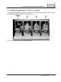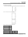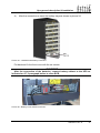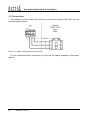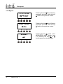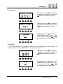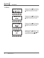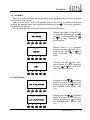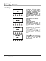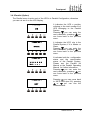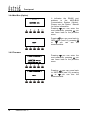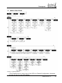
1
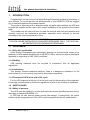
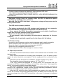
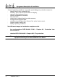
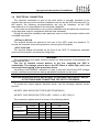
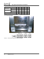
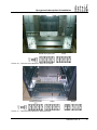
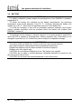
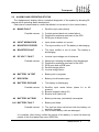
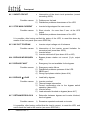
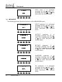
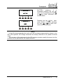
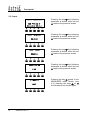
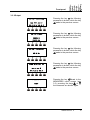
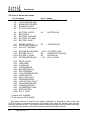
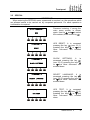
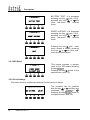
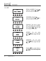
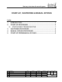
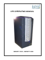
UPS OPERATING MANUAL
INFINITY 3100 – INFINITY 3300
UPS OPERATING MANUAL
Index of sections
Code
1 – UPS GENERAL DESCRIPTION AND INSTALLATION
OM497011
2 – FRONT PANEL
OM497012
3 – START-UP, SHUT-DOWN AND MANUAL BYPASS
OM497013
4 – REMOTE CONNECTION OF THE UPS
OM497014
Rev.
A
B
Descrizione
Description
First issue
Modify picture
Data
Date
16.09.05
04.03.08
Emesso
Issued
Controllato
Checked
M. Mancini
E.Simoni
A. Mangani M. Mancini
Approvato
Approved
Lingua
Language
Pagina
Page
E.Simoni
V. Gremoli
E
1
di Pag.
of Pag.
1
Codice / Code
OM497010
Ups general description & installation
UPS GENERAL DESCRIPTION AND INSTALLATION
Index
1.
INTRODUCTION................................................................................. 4
1.1
1.1.1
ISO 14001 certification.............................................................................4
1.1.2
Packing .....................................................................................................4
1.1.3
Lead battery..............................................................................................4
1.1.4
Treatment of UPS at the end of life cycle...............................................4
1.2
Safety of persons .....................................................................................4
1.2.2
Product safety ..........................................................................................5
1.2.3
Special precautions .................................................................................5
UPS GENERAL DESCRIPTION......................................................... 7
2.1
TYPOLOGY ......................................................................................................7
2.2
SYSTEM DESCRIPTION ..................................................................................8
2.2.1
Rectifier.....................................................................................................8
2.2.2
Inverter ......................................................................................................8
2.2.3
Battery and battery charger ....................................................................8
2.2.4
Static bypass ............................................................................................8
2.2.5
Manual bypass .........................................................................................8
2.2.6
Front panel................................................................................................9
2.3
Rev.
B
C
D
E
SAFETY RULES ...............................................................................................4
1.2.1
2.
3.
ENVIRONMENT................................................................................................4
OPERATING STATUS....................................................................................10
2.3.1
Normal operation ...................................................................................10
2.3.2
Load supplied by bypass due to inverter fault ....................................10
2.3.3
Rectifier failure or mains failure ...........................................................11
2.3.4
Manual bypass .......................................................................................11
INSTALLATION................................................................................ 12
Descrizione
Description
Added connection 3,3Ah batteries
Added external battery cabinet
Added 30-40kVA sizes
Added 12Ah external battery cabinet
Data
Date
21.12.05
06.02.06
29.11.07
04.03.08
Emesso
Issued
Controllato
Checked
E.Biancucci F. Orlandi
F. Orlandi V. Gremoli
M. Mancini V. Gremoli
A. Mangani M. Mancini
Approvato
Approved
M. Mancini
V. Gremoli
V. Gremoli
V. Gremoli
Lingua
Language
Pagina
Page
di Pag.
of Pag.
E
1
28
Codice / Code
OM497011
Ups general description & installation
3.1
RECEIPT OF THE UPS ................................................................................. 12
3.2
HANDLING OF THE UPS .............................................................................. 12
3.3
POSITIONING AND INSTALLATION ............................................................ 13
3.3.1
Base plan, static load and weights ...................................................... 13
3.3.2
Dimensions and distances ................................................................... 14
3.4
ELECTRICAL CONNECTION........................................................................ 15
3.4.1
3.5
Terminal board ...................................................................................... 16
BATTERY ...................................................................................................... 18
3.5.1
Battery connection and positioning .................................................... 19
3.5.1.1
3,3Ah 12V battery connection and positioning – INFINITY 10kVA 19
3.5.1.2
20kVA
7Ah / 9Ah 12V battery connection and positioning–INFINITY 10-1521
3.6
FUSES POSITIONING BCB – INFINITY 10-15-20KVA................................. 23
3.7
AS553 EXTERNAL BATTERY ...................................................................... 24
3.7.1
Dimensions and weights ...................................................................... 25
3.7.2
7Ah/9Ah/12Ah 12V battery connection and positioning .................... 26
3.7.3
Connections........................................................................................... 28
Index of pictures
Picture 1 – Block diagram............................................................................................................................. 7
Picture 2 – Normal operation...................................................................................................................... 10
Picture 3 – Load supplied by bypass.......................................................................................................... 10
Picture 4 – Rectifier failure or mains failure................................................................................................ 11
Picture 5 – Manual bypass ......................................................................................................................... 11
Picture 6 – Handling of UPS up to 40 kVA ................................................................................................. 12
Picture 7 – Base plan.................................................................................................................................. 13
Picture 8 – Dimensions and distances from the walls ................................................................................ 14
Picture 9 – Terminal board INFINITY 3100 10-15-20kVA .......................................................................... 16
Picture 10 – Terminal board INFINITY 3300 10-15-20kVA ........................................................................ 17
Picture 11 – Terminal board INFINITY 3300 30-40kVA ............................................................................. 17
Picture 12 – Paperboard 3,3Ah battery protection ..................................................................................... 19
Picture 13 – 3,3Ah battery connection........................................................................................................ 20
Picture 14 – 3,3Ah battery connected ........................................................................................................ 20
Picture 15 – Paperboard 7Ah/9Ah battery protection................................................................................. 21
Picture 16 – 7Ah/9Ah battery connection ................................................................................................... 21
2
OM497011 Rev. E
Ups general description & installation
Picture 17 – 7Ah/9Ah battery connected.................................................................................................... 22
Picture 18 – Cabling of BCB fuse holder.................................................................................................... 22
Picture 19 – Fuses positioning on the fuseholder BCB.............................................................................. 23
Picture 20 – Base plan of the external battery cabinet............................................................................... 25
Picture 21 – Dimensions of the external battery cabinet............................................................................ 25
Picture 22 – Paperboard 7Ah/9Ah/12Ah battery protection ....................................................................... 26
Picture 23 – 7Ah/9Ah/12Ah battery connection ......................................................................................... 26
Picture 24 – 7Ah/9Ah/12Ah battery connected .......................................................................................... 27
Picture 25 – Battery circuit breaker and fuses............................................................................................ 27
Picture 26 – Battery cabinet and UPS connections ................................................................................... 28
OM497011 Rev. E
3
Ups general description & installation
1.
INTRODUCTION
Congratulation for the choice of an Astrid Energy Enterprises product for the safety of
your devices. To use at the best the performances of your INFINITY UPS we suggest
you to read with attention the present manual.
The scope of this manual is to describe briefly the parts that constitute the UPS and
to guide the installer and the user to the correct installation of the system in the chosen
room.
The installer and the user will have to read this manual with care and attention and
correctly carry-out the instructions provided, especially those relevant to security
according to the country standards in force.
WARNING
THE UPS CAN BE INSTALLED BY QUALIFIED PERSONNEL ONLY. THE UPS CAN
BE OPERATED BY EXPERIENCED PERSONNEL.
1.1 ENVIRONMENT
1.1.1 ISO 14001 certification
Astrid Energy Enterprises pays particularly attention at environmental impact of its
products; for this reason development of INFINITY UPS is carried out with an ecological
approach in compliance of ISO 14001 certificate.
1.1.2 Packing
UPS packing materials must be recycled in compliance with all applicable
regulations.
1.1.3 Lead battery
This product contains lead-acid batteries. Lead is a dangerous substance for the
environment if it is not correctly recycled by specialised companies.
1.1.4 Treatment of UPS at the end of life cycle
For the UPS disposal at the end of its life cycle and for the recycling of the materials,
it’s strongly recommended to follow the regulations in force in the country of installation.
1.2 SAFETY RULES
1.2.1 Safety of persons
The UPS must be installed in a room with restricted access (qualified personnel only,
according to standard EN62040-1-2).
A UPS has its own internal power source (the battery). Consequently, the power
outlets may be energised even if the UPS is disconnected from the AC-power source.
4
OM497011 Rev. E
Ups general description & installation
CAUTION
If primary powers isolators are installed in other area from UPS area.
You must stick the following warning label on them.
“ISOLATE UNINTERRUPTIBLE POWER SUPPLY (UPS) BEFORE WORKING ON
THIS CIRCUIT”
Dangerous voltage levels are present within the UPS. It should be opened
exclusively by qualified service personnel.
Warning, after the UPS shut-down, a dangerous voltage will be present on the
battery selector BCB.
The UPS must be properly earthed.
The battery supplied with the UPS contains small amounts of toxic materials.
To avoid accidents, the directives listed below must be observed.
w Never operate the UPS if the ambient temperature and relative humidity are
higher than the levels specified in the documentation.
Never burn the battery (risk of explosion).
w Do not attempt to open the battery (the electrolyte is dangerous for the eyes
and skin).
w Comply with all applicable regulations for the disposal of the battery.
1.2.2 Product safety
A protection circuit breaker must be installed upstream and be easily accessible.
Never install the UPS near liquids or in an excessively damp environment.
Never let a liquid or foreign body penetrate inside the UPS.
Never block the ventilation grates of the UPS.
Never expose the UPS to direct sunlight or a source of heat.
1.2.3 Special precautions
The UPS connection instructions contained in this manual must be followed in the
indicated order.
w Check that the indications on the rating plate correspond to your AC-power system
and to the actual electrical consumption of all the equipment to be connected to the
UPS.
w If the UPS must be stored prior to installation, storage must be in a dry place.
w The admissible storage temperature range is -10° C to +45° C.
w If the UPS remains de-energised for a long period, we recommend that you
energise the UPS for a period of 24 hours, at least once every month. This charges the
battery, thus avoiding possible irreversible damage.
w The UPS is designed for normal climatic and environmental operating conditions as
defined in the "appendices" chapter: altitude, ambient operating temperature, relative
humidity and ambient transport and storage conditions.
w Using the UPS within the given limits guarantees its operation, but may affect the
service life of certain components, particularly that of the battery and its autonomy. The
maximum storage time of the UPS is limited due to the need to recharge its integrated
battery.
w
OM497011 Rev. E
5
Ups general description & installation
Unusual operating conditions may justify special design or protection measures:
harmful smoke, dust, abrasive dust,
humidity, vapor, salt air, bad weather or dripping,
explosive dust and gas mixture,
extreme temperature variations,
bad ventilation,
conductive or radiant heat from other sources,
strong electromagnetic fields,
radioactive levels higher than those of the natural environment,
fungus, insects, vermin, etc.,
battery operating conditions.
w
The UPS must always be installed in compliance with:
-
the requirements of HD 384.4.42 S1/A2 - Chapter 42:
thermal effects.
-
standard IEC 60364-4-482 - Chapter 482: Fire protection.
Protection from
The manufacturer declines all responsibility for damages to people or
equipment deriving from non-fulfilment of the above.
6
OM497011 Rev. E
Ups general description & installation
2.
UPS GENERAL DESCRIPTION
2.1 TYPOLOGY
All UPS covered by this manual are on-line, double conversion; the inverter supplies
always energy to the load, whether mains is available or not (according to the battery
autonomy time).
WARNING
The UPS output is energized even during mains failure, therefore in compliance with
the prescriptions of EN 62040-1, the installer will have to identify the line or the plugs
supplied by the UPS making the User aware of this fact.
This configuration guarantees the best service to the User, as it supplies clean
continuously regulated power and guarantees the voltage and frequency will be
stabilised at nominal value independently from mains status. Thanks to the double
conversion, it makes the load completely immune from micro-interruptions due to
excessive mains variation, and prevents damage to the critical load (Computer Instrumentation - Scientific equipment etc.).
Picture 1 – Block diagram
OM497011 Rev. E
7
Ups general description & installation
2.2 SYSTEM DESCRIPTION
2.2.1 Rectifier
It converts the three phase voltage of the mains into continuous DC voltage.
It uses a three phase - low harmonics - fully-controlled IGBT’s bridge.
It’s designed to supply the inverter at full load and the battery at the maximum
recharging current. This configuration is used to reduce the distortion of the current
absorbed from the mains (THD) to a value <5%.
This ensures that the rectifier does not distort the supply mains, with regard to the
other loads; it also avoids the overheating of the cables due to the harmonics
circulation.
2.2.2 Inverter
It converts the continuous voltage coming from the rectifier or from the battery into
alternating voltage stabilized in amplitude and frequency.
The inverter uses IGBT technology with a frequency commutation of approximately
15 KHz.
The control electronics is completely digital and uses a 32 Bit μP, that, by the means
of its processing capability, generates an excellent output sine-wave, which has a very
low distortion even in presence of loads having high crest factor currents.
2.2.3 Battery and battery charger
The battery is housed inside the UPS (only for INFINITY 10-15-20kVA) and in an
external battery cabinet for higher battery ratings.
The battery charger control logic is completely integrated inside the rectifier control
board; the battery is charged, according to the DIN 41773 Standard, every time it has
been partially or completely discharged and it is kept floating, even when it’s charged, to
compensate for any autodischarge.
2.2.4 Static bypass
It’s designed to transfer the load between INVERTER and MAINS, and vice-versa,
without break, and uses SCR’s as power commutation elements.
2.2.5 Manual bypass
It‘s used to by-pass the UPS, supplying the load directly to the mains in case of
maintenance or serious failure.
WARNING
The sequence of bypass switching must be carried out with respect to the procedure
indicated on the UPS and in the chapter “Start-up, shut-down and manual bypass”. The
manufacturer cannot accept responsibility for damages arising from incorrect operation.
8
OM497011 Rev. E
Ups general description & installation
2.2.6 Front panel
The front panel of the UPS, consisting of a four row alphanumeric displays plus 5
function keys, allows the complete monitoring of the UPS status.
The mimic diagram helps to understand the operating status of the UPS.
For more information see the chapter “FRONT PANEL”.
OM497011 Rev. E
9
Ups general description & installation
2.3 OPERATING STATUS
The following paragraphs show all the possible operating status of the UPS.
2.3.1 Normal operation
The inverter is supplied by the rectifier; the load, through the static switch, is supplied
directly by the inverter output.
Picture 2 – Normal operation
2.3.2 Load supplied by bypass due to inverter fault
The load is transferred to bypass through the static switch; the transfer is carried out
without interruption.
Picture 3 – Load supplied by bypass
10
OM497011 Rev. E
Ups general description & installation
2.3.3 Rectifier failure or mains failure
The inverter is supplied by the battery for the required autonomy time; the load,
through the static switch, is supplied directly by the inverter output.
Picture 4 – Rectifier failure or mains failure
2.3.4 Manual bypass
The load is supplied by the mains through the manual bypass; the operator can work
in safety on the UPS to carry out maintenance or repairing operations.
Picture 5 – Manual bypass
OM497011 Rev. E
11
Ups general description & installation
3.
INSTALLATION
3.1 RECEIPT OF THE UPS
When the UPS is received, please attend immediately to its unpacking and carry-out
an accurate visual check to be sure that the equipment has not been damaged during
transport.
IMPORTANT
In case of objections relating to damage incurred during transport these must be
immediately notified to the transportation company after receipt of the equipment.
When the UPS is not installed immediately it must be stored carefully in vertical
position, as indicated on the packing and conserved in a dry and sheltered room in its
box so that it is protected from dust.
3.2 HANDLING OF THE UPS
Before positioning the UPS, in order to avoid risks of turnover, it’s recommended to
move the system on the wood pallet on which the UPS is fixed.
Before the positioning in the final location, remove the UPS from the pallet.
The UPS can be lifted and handled using a pallet truck or a forklift.
- UPS up to 40 kVA
The UPS’s up to 40 kVA (INFINITY 3100 and 3300 series) can be handled by means
of the four wheels fixed on the bottom. The UPS technical data are shown on a label
fixed on the rear.
Picture 6 – Handling of UPS up to 40 kVA
12
OM497011 Rev. E
Ups general description & installation
3.3 POSITIONING AND INSTALLATION
The UPS must be installed in a clean and dry room, preferably not dusty. The User
must ensure that there is enough air exchange in the room so that the equipment can
be adequately cooled; if this is not guaranteed, the room must be adequately aired.
If the UPS contains the batteries internally (INFINITY 10-15-20kVA) the air exchange
with the external ambient will have to be according to EN 62040 -1, annex N.
3.3.1 Base plan, static load and weights
Picture 7 – Base plan
UPS (kVA)
INFINITY
10
15
20
30
40
3100/3300
L1 – mm
450
P1 – mm
650
L2 – mm
-
INFINITY 3100 ( kVA)
10
15
20
Weight w/o battery – kg
90
100
100
Weight with battery – kg
250
260
260
Static load – kg/m2
840
890
890
INFINITY 3300 ( kVA)
10
15
20
30
40
Weight w/o battery – kg
90
100
100
141
141
Weight with battery – kg
250
260
260
-
-
Static load – kg/m2
840
890
890
483
483
OM497011 Rev. E
13
Ups general description & installation
3.3.2 Dimensions and distances
Picture 8 – Dimensions and distances from the walls
UPS (kVA)
10
15
20
3100/3300
450
P – mm
650
H – mm
1200
Y (min.) – mm
ADD. CABINET
50
100
500
AS553
L1 – mm
500
P1 – mm
650
H1 – mm
1200
14
OM497011 Rev. E
40
3300
L – mm
X (min.) – mm
30
Ups general description & installation
3.4 ELECTRICAL CONNECTION
The electrical connection is part of the work which is normally provided by the
supplier that carries out the electrical installation and not by the UPS manufacturer. For
this reason, the following recommendations are only an indication, as the UPS
manufacturer is not responsible for the electrical installation.
In any case we recommend to carry-out the installation and the electrical connections
of the input and output in compliance with the local standards.
During the electrical installation take particular care to check the phase rotation with
a suitable instrument.
- UPS up to 20 kVA
The terminal boards are placed on the rear of the UPS, under the breakers. To
access the terminals remove the protection, removing the fixing bolts.
- UPS 30-40 kVA
The terminal boards are placed on the front of the UPS. To access the terminals
remove the front panel, removing the fixing bolts.
WARNING
The connection to the mains must be carried out with protection fuses between the
mains and the UPS.
The use of residual current devices in the line supplying the UPS is
unadvisable. The leakage current due to the RFI filters is rather high and it can
cause spurious tripping of the protection device.
According to the EN62040-1 standard, in order to take into account the UPS’ leakage
current, residual current devices having adjustable threshold can be used.
INCLUDE AN APPROPRIATE AND READLY ACCESSIBLE DISCONNECT DEVICE
IN THE FIXING WIRE CONNECTING THE UPS TO THE MAINS
To protect the output against electrical shock, use the following residual current
devices:
INFINITY 3300: DEVICE AS TYPE B (IEC/TR 60755/A2)
INFINITY 3100: DEVICE AS TYPE A (IEC 61081-1 or IEC 61091-1)
The connection cables section is shown in the following tables.
INFINITY 3100 UPS (kVA)
Input fuses (A)
Input cables (mm2)
10
15
20
Rectifier
3x25
3x32
3x32
Bypass
1x80
1x110
1x150
Rectifier
3x6
3x10
3x10
Bypass
2x16
2x25
2x35
Output cables (mm2)
2x16
2x25
2x35
(mm2)
3x6
3x6
3x6
Battery cables
OM497011 Rev. E
15
Ups general description & installation
INFINITY 3300 UPS (kVA)
Input fuses (A)
Input cables (mm2)
10
15
20
30
40
Rectifier
3x25
3x32
3x32
3x70
3x70
Bypass
-
-
-
-
-
Rectifier
4x6
4x6
4x10
4x25
4x25
-
-
-
-
-
Output cables (mm2)
Bypass
4x6
4x6
4x10
4x25
4x25
Battery cables (mm2)
3x6
3x6
3x6
3x16
3x16
3.4.1 Terminal board
Picture 9 – Terminal board INFINITY 3100 10-15-20kVA
16
OM497011 Rev. E
Ups general description & installation
Picture 10 – Terminal board INFINITY 3300 10-15-20kVA
Picture 11 – Terminal board INFINITY 3300 30-40kVA
OM497011 Rev. E
17
Ups general description & installation
3.5 BATTERY
IMPORTANT
For battery installation please respect the prescriptions of the EN62040-1 standard,
paragraph 4.5.
To obtain the battery life indicated by the battery manufacturer, the operating
temperature must remain between 0 and 25 °C. However, although the battery can
operate up to 40 °C , there will be a significant reduction of the battery life.
To avoid the formation of any kind of potentially explosive hydrogen and oxygen
mixture, suitable ventilation must be provided where the battery are installed (see
EN62040-1 annex N).
The batteries can be internal or external, however, it is recommended to install them
when the UPS is capable of charging them. Please remember that, if the battery is not
charged for periods over 2-3 months they can be subject to irreparable damage.
IMPORTANT
The infinity 3100 and 3300 from 10 kVA to 20 kVA, have internal batteries.
Servicing of batteries should performed by qualified personnel only.
Replace the batteries with the same number of block and capacity.
Replace only with original type.
CAUTION: do not dispose of batteries in fire. The battery may explode.
CAUTION: do not open or mutilate batteries. Released electrolyte is harmful to the
skin and eyes.It may be toxic.
CAUTION: do not dump the exausted batteries in the environment.
18
OM497011 Rev. E
Ups general description & installation
3.5.1 Battery connection and positioning
3.5.1.1 3,3Ah 12V battery connection and positioning – INFINITY 10kVA
1)
Remove the four screws to open the front cover and access the battery trays.
2)
Remove the paperboard cover protection from the batteries, see picture 12.
Picture 12 – Paperboard 3,3Ah battery protection
OM497011 Rev. E
19
Ups general description & installation
3)
Connect the wires as shown on the picture 13.
Picture 13 – 3,3Ah battery connection
4)
After the connection re-insert the battery trays as shown in pictures 14.
Picture 14 – 3,3Ah battery connected
Put back and fix the front cover with the four screws.
WARNING
After the battery installation, before closing BCB, check the voltage polarity in the top
and bottom of the BCB circuit breaker.
20
OM497011 Rev. E
Ups general description & installation
3.5.1.2 7Ah / 9Ah 12V battery connection and positioning–INFINITY 10-15-20kVA
1)
Remove the four screws to open the front cover and access the battery trays.
2)
Remove the paperboard cover protection from the batteries, see picture 15.
Picture 15 – Paperboard 7Ah/9Ah battery protection
3)
Connect the wires as shown on the picture 16.
Picture 16 – 7Ah/9Ah battery connection
OM497011 Rev. E
21
Ups general description & installation
4)
After the connection re-insert the battery trays as shown in picture 17.
Picture 17 – 7Ah/9Ah battery connected
Put back and fix the front cover with the four screws.
WARNING
After the battery installation, before closing BCB, check the voltage polarity in the top
and bottom of the BCB circuit breaker.
In case of not directly supplied cabling, please connect the cables to the battery
breaker as shown in the below picture.
Picture 18 – Cabling of BCB fuse holder
22
OM497011 Rev. E
Ups general description & installation
3.6 FUSES POSITIONING BCB – INFINITY 10-15-20KVA
After that the battery is correctly connected, insert the fuses and the neutral tube on
the fuseholder (BCB), as shown in the picture 19.
Picture 19 – Fuses positioning on the fuseholder BCB
OM497011 Rev. E
23
Ups general description & installation
3.7 AS553 EXTERNAL BATTERY
The battery cabinet can be used to increase the autonomy of the UPS “INFINITY 1015-20kVA” line for which the battery can be installed internally.
IMPORTANT
With the external battery the internal battery is never present.
The battery cabinet is necessary for the UPS 30-40kVA.
The battery cabinet is composed of two strings in parallel of 60 monoblocks 30+30,
for a total of 120 monoblocks of 6 elements each.
The size of the monoblocks can be 7Ah, 9Ah or 12Ah.
- AS553 for 7Ah, 9Ah and 12Ah battery blocks.
The battery circuit breaker and the battery fuses are installed inside the external
battery cabinet, see picture 25.
Concerning the installation of the external battery cabinet, refer to the details given in
paragraph 3.5.
WARNING
In order to maintain the cabinet balanced, extract only one tray at a time.
Before accessing the fuses, removing the protection, make sure that no voltage is
present.
24
OM497011 Rev. E
Ups general description & installation
3.7.1 Dimensions and weights
The dimensions and weights of the external battery cabinet are indicates here under.
Picture 20 – Base plan of the external battery cabinet
Picture 21 – Dimensions of the external battery cabinet
CABINET
AS553
L – mm
500
P – mm
650
H – mm
1200
L1 – mm
500
P1 – mm
625
L2 – mm
50
CABINET
Weight w/o battery – kg
7Ah
9Ah
12Ah
86
86
86
Weight with battery – kg
395
413
580
Static load with battery – kg/m2
1264
1321
1856
OM497011 Rev. E
25
Ups general description & installation
3.7.2 7Ah/9Ah/12Ah 12V battery connection and positioning
1)
Remove the six screws to open the front cover and access the battery trays.
2)
Remove the paperboard cover protection from the batteries, see picture 22.
Picture 22 – Paperboard 7Ah/9Ah/12Ah battery protection
3)
Connect the wires as shown on the picture 23.
Picture 23 – 7Ah/9Ah/12Ah battery connection
26
OM497011 Rev. E
Ups general description & installation
4)
After the connection re-insert the battery trays as shown in picture 24.
Picture 24 – 7Ah/9Ah/12Ah battery connected
Put back and fix the front cover with the six screws.
WARNING
After the connection of the batteries, connect battery cabinet to the UPS as
indicated on 3.7.3 paragraph before to close BCB.
Picture 25 – Battery circuit breaker and fuses
OM497011 Rev. E
27
Ups general description & installation
3.7.3 Connections
The following picture shows the electrical connection between the UPS and the
external battery cabinet.
Picture 26 – Battery cabinet and UPS connections
For the connection above mentioned you can use the cables supplied in the battery
cabinet.
28
OM497011 Rev. E
Front panel
FRONT PANEL
Index
1.
INTRODUCTION...................................................................................3
2.
DESCRIPTION......................................................................................3
2.1
MIMIC DESCRIPTION ......................................................................................3
2.2
ALARMS AND OPERATING STATUS.............................................................5
3.
LCD DISPLAY MANAGEMENT...........................................................9
3.1
DEFAULT..........................................................................................................9
3.2
MAIN MENU......................................................................................................9
3.3
MEASURES ....................................................................................................10
3.3.1
Input ........................................................................................................12
3.3.2
Output .....................................................................................................13
3.3.3
Bypass ....................................................................................................14
3.3.4
Inverter ....................................................................................................15
3.3.5
AC/DC......................................................................................................15
3.3.6
Battery.....................................................................................................16
3.4
3.4.1
UPS Status..............................................................................................17
3.4.2
History.....................................................................................................18
3.4.3
List of alarms and status .......................................................................20
3.5
Rev.
A
B
C
ALARMS .........................................................................................................17
SPECIAL.........................................................................................................21
3.5.1
UPS Reset ...............................................................................................22
3.5.2
Clock Settings ........................................................................................22
3.5.3
UPS Language........................................................................................23
3.5.4
UPS Test .................................................................................................23
3.5.5
Battery test .............................................................................................23
3.5.6
Reset history ..........................................................................................23
Descrizione
Description
First Issue
Modify alarms
Added menu
Data
Date
Emesso
Issued
Controllato
Checked
Approvato
Approved
16.09.05
10.11.05
26.04.06
M. Mancini
M. Mancini
M. Mancini
E. Simoni
E. Simoni
V. Gremoli
E. Simoni
E. Simoni
V. Gremoli
Lingua
Language
Pagina
Page
di Pag.
of Pag.
E
1
29
Codice / Code
OM497012
Front panel
3.6
INFO ............................................................................................................... 24
3.6.1
Serial Number ........................................................................................ 25
3.6.2 UPS Type.................................................................................................... 26
3.6.3
Parallel (Option)..................................................................................... 27
3.6.4
Mod-Bus (Option) .................................................................................. 28
3.6.5
Firmware ................................................................................................ 28
3.7
MENU STRUCTURE...................................................................................... 29
Index of pictures
Picture 1 - Front panel INFINITY 3100 and 3300 ......................................................................................3
Picture 2 - Structure Menu .....................................................................................................................29
2
OM497012 Rev. C
Front panel
1.
INTRODUCTION
The front panel of the UPS, consisting of a four-row alphanumeric display plus 5
function keys, allows the complete monitoring of the UPS status.
The mimic flow helps to understand the operating status of the UPS.
Picture 1 - Front panel INFINITY 3100 and 3300
2.
DESCRIPTION
2.1 MIMIC DESCRIPTION
Picture1 shows the mimic present on the display, with the names of the circuit
breakers/isolator switches of the UPS. Also the led's and blocks that comprise the UPS
are clearly identified.
LED 1
⇒
Lit-up green = Mains present at the rectifier input.
Green flashing = Wrong input phase sequence.
Off = Rectifier input mains fault.
LED 2
⇒
Lit-up green = Emergency line present and in order.
Green flashing = Wrong bypass phase sequence.
Off = Emergency line (bypass) fault.
LED 3
⇒
Lit-up green = Rectifier feeding correctly.
Green flashing = Rectifier in alarm.
Lit-up red = Inverter input voltage out of tolerance.
LED 4
⇒
Lit-up green = Battery OK.
Green flashing = Battery discharging or battery in test.
Orange flashing = BCB open.
Lit-up red = Battery test aborted.
LED 5
⇒
Lit-up green = Inverter static switch closed.
Otherwise off.
OM497012 Rev. C
3
Front panel
4
LED 6
⇒
Lit-up orange = Emergency line static switch closed.
Load retransfer blocked.
Otherwise Off
LED 7
⇒
Lit-up green = OCB circuit breaker close.
Otherwise Off
LED 8
⇒
Lit-up orange = Manual By-pass Circuit breaker closed.
Otherwise Off.
LED 9
⇒
Lit-up red = EPO push-button pressed.
Otherwise Off
LED 10
⇒
Orange flashing = Programmed service required,
contact our service department.
Lit-up orange = UPS fault, contact our service
department.
OM497012 Rev. C
Front panel
2.2 ALARMS AND OPERATING STATUS
The alphanumeric display offers a complete diagnostic of the system by showing 28
alarms and 6 operating status descriptions.
Each alarm is associated to a code that allows it to be stored in the events history.
A1 MAINS FAULT
=
Rectifier input mains failure
Possible causes: 1) Central system black-out (mains failure)
2) Distribution problems upstream of the UPS
3) RCB open or blown fuses
A2 INPUT WRONG SEQ
=
Input phase rotation not correct
A3 BOOSTER STOPPED
=
The input rectifier is off. The battery is discharging.
A4 BOOSTER FAULT
=
The input rectifier is out of order. The battery is
discharging.
A5 DC VOLT FAULT
=
Inverter input voltage out of tolerance
Possible causes: 1)
2)
3)
4)
5)
Mains input missing and battery fully discharged
Distribution problems upstream of the UPS
RCB open and or BCB open
Rectifier bridge failure
Inverter bridge failure
A6 BATTERY IN TEST
=
Battery test in progress
A7 BCB OPEN
=
Battery circuit breaker open
A8 BATTERY DISCHAR
=
The battery is discharging
Possible causes: 1) Rectifier input mains failure (alarm A1 or A2
present)
2) Booster stopped (alarm A3)
3) Booster fault (alarm A4)
A9 BATTERY AUT END
=
Battery autonomy (calculated) has expired
A10 BATTERY FAULT
=
Battery test failed
Possible causes: 1) The test has been carried out with the battery not
perfectly charged
2) One or more battery cells are damaged
It is possible, after having verified the status of the battery, to reset this alarm by
means of the front panel (see menu SPECIAL).
OM497012 Rev. C
5
Front panel
A11 SHORT CIRCUIT
=
Intervention of the short circuit protection (current
exceeding 200%)
Possible causes: 1) Problems on the load
2) Distribution problems downstream of the UPS
A12 STOP MAX CURRENT
=
Inverter bridge stopped for max current
Possible causes: 1) Short circuits for more than 5 sec. at the UPS
output
2) Distribution problems downstream of the UPS
It is possible, after having verified the status of the UPS, to reset this alarm by
means of the front panel (see menu SPECIAL).
A13 INV OUT TOLERAN
=
Inverter output voltage out of tolerance
Possible causes: 1) Intervention of the inverter current limitation for
excessive load (more than 200%)
2) Inverter failure
3) Inverter switched off (see alarm A12 or A25)
A14 BYPASS WR SEQUEN
=
Bypass phase rotation not correct (3 ph. output
only)
A15 BYPASS FAULT
=
Emergency line not available for the bypass
Possible causes: 1)
2)
3)
4)
A16 BYPASS Æ LOAD
=
Emergency mains failure
Distribution problems upstream of the UPS
SBCB open
Wrong input phase rotation (alarm A14)
Load fed by bypass
Possible causes: 1) Inverter overload
2) Thermal image intervention
3) Forced commutation due to the bypass switch
operation (alarm A22)
4) Inverter failure
5) Load retransfer blocked on bypass (alarm A17)
A17 RETRANSFER BLOCK
=
Retransfer between bypass and inverter blocked,
load on bypass
Possible causes: 1) Excessive repeated overloads on inverter
It is possible, after having verified that the load is correct, to reset the UPS, and
switch back the load to the inverter (see menu SPECIAL).
6
OM497012 Rev. C
Front panel
A18 MBYP CLOSE
=
Manual bypass breaker closed (the inverter is
shutdown)
A19 OCB OPEN
=
UPS output breaker open
A20 OVERLOAD
=
Inverter overload (load exceeding 100%). The
thermal image protection is started
A21 THERMAL IMAGE
=
Intervention of the electronic protection due to
excessive load
A22 BYPASS SWITCH
=
Closure of the commutation switch which forces
the load to bypass (maintenance)
A23 EPO PRESSED
=
Intervention of the emergency power off switch
according to the EN62040-1
It is possible, after having verified the status of the installation, to restart the UPS
by means of the front panel (see menu SPECIAL).
For an external EPO (Optional) the unit restart if the EPO push button is released.
A24 HIGH TEMPERATURE
=
High temperature on the inverter and/or rectifier
bridge
Possible causes: 1) Excessive load
2) Failure or malfunctioning of the cooling system
3) Wrong positioning of the UPS (distance from walls,
altitude)
A25 INVERTER OFF
=
The inverter has been switched off
A26 SSCI COM FAULT
=
Internal alarm
A27 EEPROM ERROR
=
Internal alarm
A28 UPS CRITICAL FAULT
=
Internal alarm
Or of the Alarms A4-A5-A12-A13-A26-A27.
A29 MAINTENANCE REQ
=
The programmed service timer has expired.
A30 COMMON ALARM
=
One or more alarms are active
A33 ASYMMETRIC LOAD
=
Check on “load asymmetry” (damage cables or
asymmetric load)
A34 SERVICE REQ
=
Contact the Service Support
OM497012 Rev. C
7
Front panel
A38 INV Æ LOAD
8
OM497012 Rev. C
=
Active only in ECO-MODE
Inverter feed load
Front panel
3.
LCD DISPLAY MANAGEMENT
3.1 DEFAULT
>> INFINITY 3100 <<
xxx kVA
>> INFINITY 3300 <<
xxx kVA
XXX V
XXX YYY ZZZ V
1Ph UPS
3Ph UPS
The default screen appears on the LCD panel when the UPS is in normal operation
(with no alarm present); it shows the name of the UPS, the nominal power and the value
of the output voltage.
Pressing a key the main menu, with all the functions and parameters, is accessed
After 5’ during which no key is pushed, if there isn’t any alarm and the battery is not
in discharge mode the Default screen is shown again. If you press the key
on this
menu, the output currents first and then time and the date are shown. If you press the
key you enter in the following menu.
3.2 MAIN MENU
The screen of the main menu, equal for 1Ph and 3Ph UPS’s, appears as follows.
< NAME >
MEASURES
< NAME >
ALARMS
< NAME >
SPECIAL
MEASURES menu. It is accessed
pressing the key
(see 3.3),
or
the
pressing the keys
other menu are scrolled down.
ALARMS menu. It is accessed
pressing the key
(see 3.4),
or
the
pressing the keys
other menu are scrolled down.
SPECIAL menu. It is accessed
pressing the key
(see 3.5),
pressing the keys
or
the
other menu are scrolled down.
OM497012 Rev. C
9
Front panel
< NAME >
INFO
INFO menu. It is accessed
pressing the key
(see 3.6),
pressing the keys
or
the
other menu are scrolled down.
3.3 MEASURES
The following pictures shows the structure of the MEASURES menu.
< MEASURES >
INPUT
< MEASURES >
OUTPUT
< MEASURES >
BYPASS
< MEASURES >
INVERTER
< MEASURES >
AC/DC
10
OM497012 Rev. C
INPUT measures. It is accessed
pressing the key
(see 3.3.1),
pressing the keys
or
the
other sub-menu are scrolled
down.
OUTPUT
measures.
It
is
accessed pressing the key
(see 3.3.2), pressing the keys
or
the other sub-menu are
scrolled down.
BYPASS
measures.
It
is
accessed pressing the key
(see 3.3.3), pressing the keys
or
the other sub-menu are
scrolled down.
INVERTER measures. It is
accessed pressing the key
(see 3.3.4), pressing the keys
or
the other sub-menu are
scrolled down.
DC measures. It is accessed
pressing the key
(see 3.3.5),
pressing the keys
or
the
other sub-menu are scrolled
down.
Front panel
< MEASURES >
BATTERY
< MEASURES >
EXIT
BATTERY
measures.
It
is
accessed pressing the key
(see 3.3.6), pressing the keys
or
the other sub-menu are
scrolled down.
Pressing the key
the main
menu screen is shown, pressing
the keys
or
the other submenu are scrolled down.
NOTE
In the following paragraphs the sub-menu will be always represented as shown in the
3Ph UPS systems; the voltage measures are always referred to the phase-to-neutral
value.
The structure of the sub-menu for the 1Ph systems remains exactly the same, but the
screens and the parameters are slightly different.
OM497012 Rev. C
11
Front panel
3.3.1 Input
INPUT VOLT/CURR
XXX YYY ZZZ V
xx.x yy.y zz.z A
INPUT FREQUENCY
XX.X Hz
INPUT POWER
XXXXX W
POWER FACTOR
X.XX
< INPUT >
EXIT
12
OM497012 Rev. C
Pressing the key
the following
parameter is shown, while the key
leads to the previous screen.
Pressing the key
the following
parameter is shown, while the key
leads to the previous screen.
Pressing the key
the following
parameter is shown, while the key
leads to the previous screen.
Pressing the key
the following
parameter is shown, while the key
leads to the previous screen.
Pressing the key
leads to the
MEASURES menu screen (see
3.3), pressing the keys
or
the measures are shown again.
Front panel
3.3.2 Output
OUTPUT VOLT/CURR
XXX YYY ZZZ V
xx.x yy.y zz.z A
OUTPUT POWER
XXXXX W
XXXXX VA
OUTPUT FREQUENCY
XX.X Hz
LOAD %/OUTPUT CF
XX YY ZZ %
xx.x yy.y zz.z
< OUTPUT >
EXIT
Pressing the key
the following
parameter is shown, while the key
leads to the previous screen.
Pressing the key
the following
parameter is shown, while the key
leads to the previous screen.
Pressing the key
the following
parameter is shown, while the key
leads to the previous screen.
Pressing the key
the following
parameter is shown, while the key
leads to the previous screen.
Pressing the key
leads to the
MEASURES menu screen (see
or
3.3), pressing the keys
the measures are shown again.
OM497012 Rev. C
13
Front panel
3.3.3 Bypass
BYPASS VOLTAGE
XXX YYY ZZZ V
BYPASS FREQUENCY
XX.X Hz
< BYPASS >
EXIT
14
OM497012 Rev. C
Pressing the key
the following
parameter is shown, while the key
leads to the previous screen.
Pressing the key
the following
parameter is shown, while the key
leads to the previous screen.
Pressing the key
leads to the
MEASURES menu screen (see
3.3), pressing the keys
or
the measures are shown again.
Front panel
3.3.4 Inverter
INVERTER VOLT/CURR
XXX YYY ZZZ V
xx.x yy.y zz.z A
INVERTER FREQUENCY
XX.X Hz
< INVERTER >
EXIT
Pressing the key
the following
parameter is shown, while the key
leads to the previous screen.
Pressing the key
the following
parameter is shown, while the key
leads to the previous screen.
Pressing the key
leads to the
MEASURES menu screen (see
3.3), pressing the keys
or
the measures are shown again.
3.3.5 AC/DC
This menu is active only when the battery is not discharging. If the battery is in
discharge mode the menu BATTERY is automatically shown.
AC/DC VOLTAGE
POS. XXX V
NEG. YYY V
< AC/DC >
EXIT
Pressing the key
the following
parameter is shown, while the key
leads to the previous screen.
Pressing the key
leads to the
MEASURES menu screen (see
3.3), pressing the keys
or
the measures are shown again.
OM497012 Rev. C
15
Front panel
3.3.6 Battery
BATTERY VOLT/CURR
POS: XXX V xx.x A
NEG: YYY V yy.y A
BATTERY TYPE
XXX Ah
BATTERY AUTONOMY
XXX min
YY %
< BATTERY >
EXIT
16
OM497012 Rev. C
Pressing the key
the following
parameter is shown, while the key
leads to the previous screen.
Pressing the key
the following
parameter is shown, while the key
leads to the previous screen.
Pressing the key
the following
parameter is shown, while the key
leads to the previous screen.
Pressing the key
leads to the
MEASURES menu screen (see
or
the
3.3), pressing the key
measures are shown again.
Front panel
3.4 ALARMS
This menu, when selected, shows the status of the equipment and the current alarms
are shown (see list below).
Each time an alarm occurs, the display goes to this menu to indicate the alarms
present; the audible alarm can be silenced pressing the key . The exit is disabled if
the alarm is not silenced.
The following pictures shows the structure of the ALARMS menu.
< ALARMS >
UPS STATUS
< ALARMS >
HISTORY
< ALARMS >
EXIT
Alarms and status of the UPS. It
is accessed pressing the key
(see 3.4.1), pressing the keys
or
the other sub-menu are
scrolled down.
Alarms history. It is accessed
pressing the key
(see 3.4.2),
pressing the keys
or
the
other sub-menu are scrolled
down.
Pressing the key
the main
menu screen is shown, pressing
the keys
or
the other submenu are scrolled down.
3.4.1 UPS Status
< UPS STATUS >
1st alarm/status
< UPS STATUS >
Last alarm/status
Pressing the key
the status
and/or the alarm of the UPS are
leads to
shown, while the key
the ALARMS menu screen (see
3.4).
Pressing the key
the status
and/or the alarm of the UPS are
shown, while the key
leads to
the ALARMS menu screen (see
3.4).
OM497012 Rev. C
17
Front panel
3.4.2 History
< HISTORY >
1st alarm/status
Date
Time
< HISTORY >
2nd alarm/status
Date
Time
< HISTORY >
3rd alarm/status
Date
Time
< HISTORY >
Last alarm/status
Date
Time
Pressing the key
the following
alarm is shown; pressing the key
exit the history, leading to the
ALARMS menu screen (see 3.4).
Pressing the key
the following
alarm is shown; pressing the key
exit the history, leading to the
ALARMS menu screen (see 3.4).
Pressing the key
the following
alarm is shown; pressing the key
exit the history, leading to the
ALARMS menu screen (see 3.4).
Pressing the key
the first alarm
is shown again; pressing the key
exit the history, leading to the
ALARMS menu screen (see 3.4).
The first alarm shown is the most recent in order of time; a new alarm makes all the
alarms shift one position, clearing the oldest event.
For each event is shown the alarm code, the date and time; an asterisk next to the
code indicates that the alarm has cleared at the date and time indicated. The following
example shows two possible screens.
< HISTORY >
2/6
25-12-2005
18
OM497012 Rev. C
A01
23:08
Alarm A1 (MAINS FAULT)
happened on 25/12/05 at 23:08.
The position of this event in list is
the second. The total events
stored in the history are six.
Front panel
< HISTORY >
3/6
25-12-2005
A01*
23:12
Reset of alarm A1 (MAINS
FAULT) on 25/12/05 at 23:12.
The position of this event in the
list is the third. The total events
stored in the history are six.
OM497012 Rev. C
19
Front panel
3.4.3 List of alarms and status
List of alarms
A1
MAINS FAULT
A2
INPUT WRONG SEQ
A3
BOOSTER STOPPED
A4
BOOSTER FAULT
A5
DC VOLTAGE FAULT
List of status
S1
BOOSTER OK
A6
A7
A8
A9
A10
BATTERY IN TEST
BCB OPEN
BATTERY DISCHAR
BATTERY AUT END
BATTERY FAULT
S2
BATTERY OK
A11
A12
A13
SHORT CIRCUIT
STOP MAX CURRENT
INV OUT TOLERAN
S3
INVERTER OK
A14
A15
(**)A16
A17
BYPASS WR SEQUEN
BYPASS FAULT
BYPASS Æ LOAD
RETRANFER BLOCK
(**)S4
S5
S6
(*) S7
INV FEED LOAD
INVERTER SYNCHRO
BYPASS OK
BYP Æ LOAD
A18
A19
A20
A21
A22
A23
A24
A25
A26
A27
A28
A29
A30
A33
A34
(*)A38
MBYP CLOSE
OCB OPEN
OVERLOAD
THERM IMAGE
BYPASS SWITCH
EPO PRESSED
HIGH TEMPERATURE
INVERTER OFF
SSCI COM FAULT
EEPROM ERROR
UPS CRITICAL FAULT
MAINTENANCE REQ
COMMON ALARM
ASYMMETRIC LOAD
SERVICE REQ
INV Æ LOAD
(*) Active in ECO-MODE
(**) Not active in ECO-MODE
The status shown in this list are always displayed in ascending order when the
STATUS menu is entered, the alarms are shown when they are present and must be
silenced with the buzzer. The alarms remain displayed whilst they are present and they
are automatically stored in the event history memory with date and time.
20
OM497012 Rev. C
Front panel
3.5 SPECIAL
IMPORTANT
When entering the SPECIAL menu a password is required, as the operations which
are allowed needs to be carried out by competent personnel. For each operation a
confirmation is required.
ENTER PASSWORD:
000
< SPECIAL >
RESET
< SPECIAL >
CLOCK SETTINGS
< SPECIAL >
SELECT LANGUAGE
< SPECIAL >
UPS TEST
Password entering; if wrong the
main menu screen is shown
again. Use the
and
to select
the numbers, then confirm by
.
UPS RESET. It is accessed
pressing the key
(see 3.5.1),
pressing the keys
or
the
other sub-menu are scrolled
down.
CLOCK
SETTINGS.
It
is
accessed pressing the key
(see 3.5.2), pressing the keys
or
the other sub-menu are
scrolled down.
SELECT LANGUAGE. It is
accessed pressing the key
(see 3.5.3), pressing the keys
or
the other sub-menu are
scrolled down.
UPS TEST. It is accessed
pressing the key
(see 3.5.4),
pressing the keys
or
the
other sub-menu are scrolled
down.
OM497012 Rev. C
21
Front panel
< SPECIAL >
BATTERY TEST
< SPECIAL >
RESET HISTORY
< SPECIAL >
EXIT
BATTERY TEST. It is accessed
pressing the key
(see 3.5.5),
pressing the keys
or
the
other sub-menu are scrolled
down.
RESET HISTORY. It is accessed
(see 3.5.6),
pressing the key
pressing the keys
or
the
other sub-menu are scrolled
down.
Pressing the key
the main
menu screen is shown, pressing
or
the other subthe keys
menu are scrolled down.
3.5.1 UPS Reset
< RESET >
PRESS RESET
TO RESET UPS
This menus provides a general
reset of the UPS status pressing
.
the key
leads to the
Pressing the key
special menu (see 3.5).
3.5.2 Clock Settings
This menu allows to update time settings for the history of alarms.
< CLOCK SETTINGS >
25-12-2001
22
OM497012 Rev. C
18:48
The numbers can be modified
with the key
or
and they are
confirmed by pressing
.
Pressing the key
leads to
the special menu (see 3.5).
Front panel
3.5.3 UPS Language
< SELECT LANGUAGE >
2 – ENGLISH
The language can be modified
with the key
or
and they are
confirmed by pressing
.
Pressing the key
leads to
the special menu (see 3.5).
3.5.4 UPS Test
< UPS TEST >
PRESS RESET
FOR COMMUTATION
Pressing the key
causes
the commutation to bypass.
Pressing the key
leads to the
special menu (see 3.5).
3.5.5 Battery test
The BATTERY TEST cannot be started if this option is not enabled.
< BATTERY TEST >
PRESS RESET
TO START TEST
Pressing the key
the
battery test is started. Pressing
the key
leads to the special
menu (see 3.5).
WARNING - POSSIBLE LOSS OF LOAD!
This test can affect the continuity of supply to the loads, if the battery is not fully
charged.
3.5.6 Reset history
< RESET HISTORY >
PRESS RESET
TO CLEAR HISTORY
Pressing the key
the
alarms
history
is
cleared.
Pressing the key
leads to the
special menu (see 3.5).
WARNING
This operation causes the cancellation of the events stored in the history memory.
OM497012 Rev. C
23
Front panel
3.6 INFO
< INFO >
SERIAL NUMBERS
< INFO >
UPS MODEL
< INFO >
PARALLEL
< INFO >
MODBUS
< INFO >
FIRMWARE
< INFO >
EXIT
24
OM497012 Rev. C
SERIAL NUMBERS. Pressing
(see 3.6.1), and then
or
you
can look trough the sub-menu.
UPS MODEL. Pressing
you
(see 3.6.2)and then or
can look trough the sub-menu.
PARALLEL. This menu is active
only if our UPS is set in parallel.
(see 3.6.3),and
You can enter
then pressing
or
you can
look trough the sub-menu.
MODBUS.
You
can
enter
pressing
(see 3.6.4), and then
or
to look trough the submenu.
FIRMWARE. You can enter
pressing
(see 3.6.5), and then
or
to look trough the submenu.
Pressing
you come back to
the main menu, and then pressing
or
you can look trough the
sub-menu.
Front panel
3.6.1 Serial Number
< UPS SERIAL NUMBER>
<< XXXXXXXXX >>
< OEM SERIAL NUMBER >
<< XXXXXXXXX >>
< SERIAL NUMBER >
EXIT
The UPS serial number set by the
Supplier.
Pressing
you can enter the
next parameter; pressing
you
come back to the main menu.
Customized Serial Number.
you can enter the
Pressing
next parameter while pressing
you come back to the main menu.
Pressing
you come back to the
INFO menu. (see 3.6), pressing
or
you can see the
measurements.
OM497012 Rev. C
25
Front panel
3.6.2 UPS Type
< UPS Type>
3/3
< UPS Type >
ON-LINE
< UPS Type >
SINGLE
< UPS Type >
EXIT
26
OM497012 Rev. C
It indicates UPS’ input /output.
You can see if the l’UPS is
Threephase/ Threephase 3/3 or
Threephase / Singlephase 3/1.
you can enter the
Pressing
next parameter; pressing
you
can come back to the previous
menu
It indicates the UPS topology:
ON-LINE
ECO-MODE
FREQ CONVERTER
you can enter the
Pressing
next parameter; pressing
you
can come back to the previous
menu
It indicates the UPS configuration:
Parallel or Stand Alone
Pressing
you can enter the
you
next parameter; pressing
can come back to the previous
menu
Pressing
you can come back to
INFO menu (see 3.6), pressing
or
you can see the
measurements.
Front panel
3.6.3 Parallel (Option)
The Parallel menu is active only of the UPS is in Parallel Configuration, otherwise
you can not see it on the LCD display.
< PARALLEL >
n/N
< PARALLEL >
MASTER
< PARALLEL >
1 2 3 4 5 6 E
M S - - - -
< PARALLEL >
EXIT
It indicates the UPS n position
referring to the total number N of
UPS belonging to the Parallel
System.
Pressing
you can enter the
next parameter; pressing
you
can come back to the previous
menu.
It indicates the UPS’ rule in the
Parallel System; if it is Master or
Slave.
Pressing
you can enter the
you
next parameter; pressing
can come back to the previous
menu.
It indicates both the configuration
status and the comunication
status of the Parallel System.
Please see the Parallel Kit
Manual or the Parallel Operating
Manual for further information.
you can enter the
Pressing
next parameter; pressing
you
can come back to the previous
menu.
Pressing
you can come back
to INFO menu (see 3.6), pressing
or
you can see the
measurements.
OM497012 Rev. C
27
Front panel
3.6.4 Mod-Bus (Option)
< MODBUS >
ADDRESS 101
< MODBUS >
EXIT
It indicates the RS485 port
address
to
the
MOD-BUS
Comunication System (Option).
Please see the Option Manual
for further information.
Pressing
you can enter the
next parameter; pressing
you
can come back to the previous
menu.
Pressing
you can come back to
INFO menu (see 3.6), pressing
or
you can see the
measurements.
3.6.5 Firmware
< VERS FIRMWARE >
BOOSTER:xx.yy
INVERTER:xx.yy
< VERS FIRMWARE >
EXIT
28
OM497012 Rev. C
Pressing
you can enter the
next parameter; pressing
you
can come back to the previous
menu.
Pressing
you can come back
to INFO menu (see 3.6), pressing
or
you can see the
measurements.
Front panel
3.7 MENU STRUCTURE
Picture 2 - Structure Menu
(*)The Parallel menu is active only of the UPS is in Parallel Configuration, otherwise
you can not see it on the LCD display.
OM497012 Rev. C
29
Start-up, shut-down & manual bypass
START-UP, SHUTDOWN & MANUAL BYPASS
Index
1.
INTRODUCTION...................................................................................2
2.
START-UP PROCEDURE ....................................................................2
2.1
START-UP BASIC TROUBLESHOOTING.......................................................3
3.
SHUTDOWN PROCEDURE .................................................................4
4.
MANUAL BYPASS PROCEDURE.......................................................4
5.
START-UP FROM MANUAL BY-PASS...............................................5
Rev.
A
Descrizione
Description
First Issue
Data
Date
Emesso
Issued
Controllato
Checked
Approvato
Approved
16.09.05
M. Mancini
E. Simoni
E. Simoni
Lingua
Language
Pagina
Page
di Pag.
of Pag.
E
1
5
Codice / Code
OM497013
Start-up, shut-down & manual bypass
1.
INTRODUCTION
Before carrying out whatever procedure described in this chapter, read carefully the
instructions, in order to avoid possible damages to persons or thing due to wrong
manoeuvre.
2.
START-UP PROCEDURE
WARNING
Before switching on the UPS, make sure:
1) the emergency power off “EPO” push-button, if provided, is in the release position;
if not, press it and proceed with the start-up procedure;
2) the input and output phase rotation is correct.
NOTE
The breaker BCB is installed inside the UPS’s up to 20 kVA. Batteries and the relevant
breaker for UPS systems having higher power are external.
WARNING
Do not close the battery breaker BCB before it’s required by the front panel. Serious
damages to UPS internal parts may occur if the breaker is closed before the rectifier is
started-up.
Nr.
LCD DISPLAYING
1
2
BLANK
UPS START UP
WAIT PLEASE
3
BOOSTER START UP
WAIT PLEASE
4
INVERTER START UP
WAIT PLEASE
5
BYPASS START UP
CLOSE SBCB
BYPASS START UP
WAIT PLEASE
6
2
OM497013 Rev. A
ACTION
UPS OPERATION
Close RCB
The rectifier is supplied and the DC voltage
increases up to the nominal value. All LED’s
in the front panel are lit green.
The microprocessor checks all the start-up
conditions are ok.
The rectifier IGBT bridge starts to modulate
and the inverter intput voltage reaches the
nominal value. After a while LED #3 is lit
green.
The inverter IGBT bridge starts to modulate
and the inverter output voltage reaches the
nominal value. After a while the inverter
static switch thyristors close. LED #5 is lit
green.
Close SBCB
The microprocessor checks that all the bypass parameters (voltage, phase sequence,
frequency) are within the tolerance limits.
LED #2 is lit green.
Start-up, shut-down & manual bypass
7
8
9
10
End
BATTERY START UP
CLOSE BCB
BATTERY START UP
WAIT PLEASE
START UP END
CLOSE OCB
START UP END
WAIT PLEASE
Close BCB
The microprocessor checks all the
conditions for the following step are ok. After
a while LED #4 is lit green.
Close OCB
UPS MODEL
OUTPUT VOLTAGE
The microprocessor checks that all the
output
parameters
(voltage,
current,
frequency) are within the tolerance limits.
LED #7 is lit green.
After a while the default screen is shown
2.1 START-UP BASIC TROUBLESHOOTING
This paragraph provides the basic information if any alarms occur during the start-up
procedure. In case the problem cannot be solved contact the service department.
1) After closing RCB the LCD display is still blank
• Check the input voltage.
• Check the rectifier protection fuses F1-F2-F3; they are inside the breaker
RCB on INFINITY 3100 and 3300 up to 20 kVA.
2) After the step #2 the unit doesn’t switch to step #3 and shows the alarm A1 –
Mains fault
• Check if the alarm A2 is active. In case of alarm active, check the phase
rotation of the line input.
• Check the rectifier protection fuses F1-F2-F3; they are inside the breaker
RCB on INFINITY 3100 and 3300 up to 20 kVA.
3) After the step #3 the unit shows alarms messages
• Open RCB and check the UPS connections.
• Close RCB and try to restart the UPS.
4) After the step #4 the unit shows alarms messages
• Check the EPO push-button (if provided outside the unit) is in the release
position.
• Open RCB and check the UPS connections.
• Close RCB and try to restart the UPS.
5) After the step #10 the unit shows the alarm A15 – Bypass fault
• Check if the alarm A14 is active. In case of alarm active, check the phase
rotation of the by-pass line input.
• Check the static switch protection fuses; they are inside the breaker SBCB
on on INFINITY 3100 and 3300 up to 20 kVA.
6) After the step #10 the unit shows the alarm A7 – BCB open
• Check the fuses inside the breaker BCB.
OM497013 Rev. A
3
Start-up, shut-down & manual bypass
•
3.
Nr.
If an external battery cabinet is installed check the interconnections
between the auxiliary contact of the battery breaker (in the external
cabinet) and the terminals Bac1-Bac2 of the UPS.
SHUTDOWN PROCEDURE
ACTION
1
Open OCB
2
Open BCB
3
Open SBCB
4
Open RCB
LCD DISPLAYING
A30 GENERAL ALARM The supply to the load is interrupted. LED #7
off.
A19 OCB OPEN
A7 BCB OPEN
The battery is disconnected from the
rectifier. LED #4 orange flashing
A15 BYP FAULT
The by-pass line is disconnected. LED #2
off.
A1 MAINS FAULT
5
4.
UPS OPERATION
BLANK
The rectifier and inverter are switched off.
Shut-down procedure end.
MANUAL BYPASS PROCEDURE
WARNING
During manual bypass operation the load is supplied directly by the mains, therefore
continuous supply is not guaranteed.
Nr.
4
ACTION
LCD DISPLAYING
UPS OPERATION
1
Switch
“NORMAL
BYPASS”
selector on
BYPASS
A30 GENERAL ALARM The load is transferred to the by-pass static
switch. LED #5 off, LED #6 lit orange.
A22 BYP SWITCH
A16 BYP Æ LOAD
2
Close MBCB
A31 MBYPBUS CLOSE The load is supplied by the mains through
A25 INVERTER STOP the manual by-pass circuit breaker.
The inverter is switched off. LED #8 lit
A18 MBY CLOSE
orange.
3
Open OCB
4
Open SBCB
5
Open BCB
A7 BCB OPEN
6
Open RCB
BLANK
OM497013 Rev. A
A19 OCB OPEN
LED #7 Off. The Inverter Restart.
A15 BYPASS FAULT LED #5 lit green, LED #6 Off, LED #2 Off no
/A25 INVERTER STOP Bypass.
The Battery is disconnected.
LED #4 flashing orange.
The load is now supplied directly by the
mains through the manual by-pass circuit
breaker. The UPS is isolated.
Start-up, shut-down & manual bypass
5.
START-UP FROM MANUAL BY-PASS
Before the start-up from manual by-pass (after a maintenance or repairing) check
that the “NORMAL-BYPASS” switch is in BYPASS position.
Nr.
LCD DISPLAYING
1
2
BLANK
UPS START UP
WAIT PLEASE
3
BYPASS STARTUP
CLOSE SBCB
BYPASS STARTUP
WAIT PLEASE
4
5
6
7
8
9
10
11
ACTION
UPS OPERATION
Close RCB
Close SBCB
The rectifier is supplied and the DC
voltage increases up to the nominal
value. All LED’s in the front panel are lit.
The microprocessor checks all the startup conditions are ok. LED’s #1 is lit
green and #6 are lit orange. LED #8 is lit
orange.
LED #1 LED #3 is lit green, LED #6 LED
#8 is lit orange.
The microprocessor checks that all the
by-pass parameters (voltage, phase
sequence, frequency) are within the
tolerance limits. LED #2 is lit green. The
by-pass static switch is closed, LED #6
is lit orange.
CLOSE BCB
The microprocessor checks all the
Close
BCB
conditions for the following step are ok.
WAIT PLEASE
LED #4 is lit green.
CLOSE OCB
The load is supplied by the by-pass
Close
OCB
static switch. The breaker MBCB is still
WAIT PLEASE
closed. LED #7 is lit green.
OPEN MBCB
The load is now supplied by the by-pass
Open
MBCB
static switch only and the inverter can be
WAIT PLEASE
started-up. LED #8 is off.
The inverter IGBT bridge starts to
INVERTER START UP
modulate and the inverter output voltage
WAIT PLEASE
reaches the nominal value. The
microprocessor
checks
the
synchronisation with the by-pass line.
MOVE BYP-SWITCH Move the “NORMAL- The load is transferred to the inverter
BYPASS” switch on static switch. LED #5 is lit green. LED #6
WAIT PLEASE
NORMAL
is off.
START UP END
The microprocessor checks that all the
output parameters (voltage, current,
WAIT PLEASE
frequency) are within the tolerance limits.
UPS MODEL
After a while the default screen is shown
OUTPUT VOLTAGE
OM497013 Rev. A
5
Remote connection of the UPS
REMOTE CONNECTION OF THE UPS
Index
1.
REMOTE CONNECTIONS BY RS232 OR USB...................................2
1.1
INTRODUCTION...............................................................................................2
1.2
CONNECTION RS232 PORT ...........................................................................2
1.3
CONNECTION BY USB PORT.........................................................................3
2.
REMOTE CONNECTION BY RS485 (OPTIONAL) .............................3
2.1
3.
DESCRIPTION..................................................................................................3
REMOTE CONNECTION BY SRC (OPTIONAL).................................3
3.1
DESCRIPTION..................................................................................................3
Index of pictures
Picture 1 – RS232-USB Ports ................................................................................................................. 2
Picture 2 – RS232 connection cable........................................................................................................ 2
Rev.
A
B
Descrizione
Description
First Issue
Modify par. 2 and 3
Data
Date
16.09.05
20.10.05
Emesso
Issued
Controllato
Checked
M. Mancini E. Simoni
E.Biancucci M. Mancini
Approvato
Approved
Lingua
Language
Pagina
Page
di Pag.
of Pag.
E. Simoni
E. Simoni
E
1
3
Codice / Code
OM497014
Remote connection of the UPS
1.
REMOTE CONNECTIONS BY RS232 OR USB
1.1 INTRODUCTION
The INFINITY UPS is provided with a RS232 port and an USB port as standard.
Picture 1 – RS232-USB Ports
1.2 CONNECTION RS232 PORT
The UPS can be connected to a monitoring Device/Software through a RS232
standard port with a RS232 standard cable (Male-Female DB9).
The UPS data on the RS232 are transferred according to a Question-Answer
Proprietary Protocol.
The Settings parameters of the RS232 on the INFINITY are:
Baud Rate = 9600
Parity = None
Data = 8
BitStop = 1
NOTE
Ask the UPS Manufacturer for more information about the UPS Protocol
The connection cable is built as follows:
Picture 2 – RS232 connection cable
2
OM497014 Rev. B
Remote connection of the UPS
1.3 CONNECTION BY USB PORT
Instead of using the RS232 serial connection it is possible to connect a monitoring
device through the USB Port. In this case when the USB cable is plugged into the USB
port and to the monitoring Device (ex. PC) the RS232 is automatically switched off.
The USB Driver is on the CD Monitoring Software.
The USB cable is a standard USB Cable.
2.
REMOTE CONNECTION BY RS485 (OPTIONAL)
2.1 DESCRIPTION
When required it’s possible to install on the INFINITY UPS the optional card RS485
SLOT_REM. Through the RS485 interface the UPS can be remotely monitored up to
400m. The protocol implemented on the RS485 port is a MOD-BUS RTU standard
protocol.
For further information about the functions of the MOD-BUS protocol and the
installation of the card refer to the “Remote connection by RS485 - Installation and user
manual”.
3.
REMOTE CONNECTION BY SRC (OPTIONAL)
3.1 DESCRIPTION
The SRC card is used to repeat to a remote location some UPS statuses and alarms,
by means of SPDT (Single-Pole-Double-Throw) voltage free contacts.
In normal condition with no Alarms and all Statuses OK, all the relays are energized.
For further information about the installation of the card refer to the “SRC Signalling
Remote Card - Installation and user manual”.
OM497014 Rev. B
3
FACTORY & HEAD OFFICE
Viale Europa, 22 - Loc. Ponte d’Arno
52018 CASTEL SAN NICCOLO’ (AR)
Phone: +39-0575-509701
Fax: +39-0575-500032
http://www.astridups.it