1
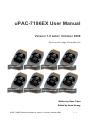
uPAC-7186EX User Manual
Version 1.0 beta1, October 2008
Service and usage information for
uPAC-7186EX
uPAC-7186EXD
uPAC-7186EX-SD
uPAC-7186EXD-SD
uPAC-7186EX-FD
uPAC-7186EX-SM
uPAC-7186EXD-FD
uPAC-7186EXD-SM
Written by Hans Chen
Edited by Anna Huang
uPAC-7186EX Series User Manual, Version 1.0 beta1, October 2008
--- 1
Important Notices
Warranty
All products manufactured by ICP DAS are under warranty regarding defective materials
for a period of one year, beginning from the date of delivery to the original purchaser.
Warning
ICP DAS assumes no liability for any damage resulting from the use of this product.
ICP DAS reserves the right to change this manual at any time without notice. The
information furnished by ICP DAS is believed to be accurate and reliable. However, no
responsibility is assumed by ICP DAS for its use, not for any infringements of patents or
other rights of third parties resulting from its use.
Copyright
Copyright @ 2007 by ICP DAS Co., Ltd. All rights are reserved.
Trademark
The names used for identification only may be registered trademarks of their respective
companies.
uPAC-7186EX Series User Manual, Version 1.0 beta1, October 2008
--- 2
Table of Contents
Table of Contents................................................................................................................... 3
1.
2.
Introduction ..................................................................................................................... 6
1.1.
Features ............................................................................................................... 8
1.2.
Specifications ..................................................................................................... 11
1.3.
Overview ............................................................................................................ 15
1.4.
Dimension .......................................................................................................... 16
1.5.
Companion CD .................................................................................................. 17
Quick Start .................................................................................................................... 18
2.1.
Installing the uPAC-7186EX .................................................................... 18
2.1.2.
Mounting the I/O Expansion Bus ............................................................. 20
2.1.3.
Mounting the I/O Expansion Bus ............................................................. 21
2.1.4.
Wiring connections .................................................................................. 22
Software installation ........................................................................................... 24
2.3.
MiniOS7 Utility for downloading programs ......................................................... 26
2.3.1.
Establishing a connection between the Host PC and the uPAC-7186EX 26
2.3.2.
Uploading and executing programs on uPAC-7186EX............................ 35
2.3.3.
Making programs start automatically ....................................................... 36
MiniOS7 Utility for updating OS image ............................................................... 37
Your First Program on uPAC-7186EX .......................................................................... 40
3.1.
4.
2.1.1.
2.2.
2.4.
3.
Hardware installation.......................................................................................... 18
Setting up the compiler ...................................................................................... 40
3.1.1.
Installing the Compiler ............................................................................. 41
3.1.2.
Setting up the environment variables ...................................................... 46
3.2.
API for uPAC-7186EX ........................................................................................ 49
3.3.
Build and run your first program ......................................................................... 51
API and Demo Program Reference .............................................................................. 63
uPAC-7186EX Series User Manual, Version 1.0 beta1, October 2008
--- 3
4.1.
API for COM port ............................................................................................... 65
4.1.1.
Types of COM port functions ................................................................... 66
4.1.2.
API for MiniOS7 COM port ...................................................................... 67
4.1.3.
API for standard COM port ...................................................................... 70
4.1.4. Comparing with MiniOS7 COM port function and Standard COM port
function 73
4.1.5.
Request/Response protocol define on COM port .................................... 74
4.2.
API for I/O modules ............................................................................................ 75
4.3.
API for EEPROM ............................................................................................... 78
4.4.
API for Flash Memory ........................................................................................ 80
4.5.
API for NVRAM and RTC ................................................................................... 82
4.6.
API for 5-Digit LED ............................................................................................. 84
4.7.
API for Timer and WatchDogTimer .................................................................... 86
4.8.
API for WatchDog Timer (WDT) ......................................................................... 88
Appendix A. Frame Ground ................................................................................................. 90
Appendix B. What is MiniOS7 .............................................................................................. 91
Appendix C. What is MiniOS7 Utility .................................................................................... 92
Appendix D. What is VxComm Utility ................................................................................... 93
Appendix E. More C Compiler Settings ................................................................................ 94
E.1. Turbo C 2.01 ......................................................................................................... 94
E.2. BC++ 3.1. IDE ....................................................................................................... 97
E.3. MSC 6.00 ............................................................................................................ 101
E.4. MSVC 1.50 .......................................................................................................... 103
Appendix F. Application of RS-485 Network ...................................................................... 107
F.1. Basic RS-485 network ......................................................................................... 107
F.2. Daisy chain RS-485 network ............................................................................... 108
F.3. Star type RS-485 network.................................................................................... 109
F.4. Random RS-485 network .................................................................................... 111
uPAC-7186EX Series User Manual, Version 1.0 beta1, October 2008
--- 4
F.5. Pull-High/Pull-Low Resistors ............................................................................... 112
F.5.1. uPAC-7186EX as a Master ....................................................................... 112
F.5.2. uPAC-7186EX as a slave .......................................................................... 113
uPAC-7186EX Series User Manual, Version 1.0 beta1, October 2008
--- 5
1. Introduction
The uPAC-7186EX is a palm-size programmable automation controller that with
Ethernet, RS-232 and RS-485 communication. ICP DAS provides easy-to-use
Software development tool kits (Framework, Xserver, VxComm, Modbus function
Library). Users can use them to easily integrate serial devices to have
Ethernet/Internet communication ability and through the standard Modbus protocol to
Communicate with SCADA software (Indusoft, ISaGARF, DasyLab, Trace Mode,
Citect, iFix and so forth).
For the hardware, it also supports for I/O expansion bus interface. The I/O expansion
bus can be used to implement various I/O functions such as D/I, D/O, A/D, D/A,
Timer/Counter, UART, flash memory, battery backup SRAM, ASIC key and other I/O
functions. This I/O expansion bus can implement nearly all kinds of I/O functions, but
only one expansion board can be added. There are more than 50 boards available for
uPAC-7186EX series module so far.
uPAC-7186EX Series User Manual, Version 1.0 beta1, October 2008
--- 6
Package List
In addition to this manual, the shipping package includes the following items:
One uPAC-7186EX module
One download cable (CA0910)
One companion CD containing software drivers and digital versions of the user
manuals
One copy of the release notes
uPAC-7186EX Series User Manual, Version 1.0 beta1, October 2008
--- 7
1.1. Features
Support for Virtual COM technology
PC can create virtual COM ports to map the RS-232, RS-485 of uPAC-7186EX
series module using the VxComm technology. The software running on the
PC can operate the virtual COM ports like a standard COM port to access the serial
devices connect to the uPAC-7186EX. In other words, the original software
developed for the serial devices can access the serial devices via the
Ethernet/Internet without any modification.
Each PC can control up to 256 COM ports (including real COM ports). Using the I/O
expansion board, each uPAC-7186EX can have up to 8 COM ports.
Support Modbus Protocol
Using the Modbus firmware, uPAC-7186EX offers following Modbus features:
1. Modbus/TCP/RTU/ASCII slave
2. Modbus/TCP/RTU/ASCII master
3. Gateway for Modbus/TCP to Modbus/RTU
VxComm Technique Supported
VxComm technique is used to create virtual COM ports on PC (for windows 2K/XP)
to map remote COM ports of PDS-700, I-7188E, I-8000 and uPAC-7186EX over the
Ethernet. Using the technique, RS-232/485 software can access devices locally (via
the physical RS-232/485 bus) or remotely (via the Ethernet). The RS-232/485
software only needs to change COM port number from the physical COM port to
virtual COM port.
Ethernet Protocols
TCP, UDP, IP, ICMP and ARP.
uPAC-7186EX Series User Manual, Version 1.0 beta1, October 2008
--- 8
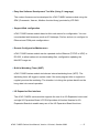
Easy-Use Software Development Tool Kits (Using C Language)
The custom firmware can be developed for uPAC-7186EX series module using the
SDK (Framework, Xserver, Modbus function libray) provided by ICP DAS.
Support Web configuration
uPAC-7186EX series module has a build-in web server for configuration. You can
use standard web browsers (such as IE, Netscape, Firefox, and etc) to configure its
Ethernet and COM ports configurations.
Remote Configuration/Maintenance
uPAC-7186EX series module can be operated via the Ethernet (TCP/IP or UDP) or
RS-232, to allow tasks such as downloading files, configuration updating the
MiniOS7 image etc.
Built-in Watchdog Timer (WDT)
uPAC-7186EX series module includes an internal watchdog timer (WDT). The
watchdog timer will trigger a system reset if the main program fails or neglects to
regularly service the watchdog. The intention is to bring the system back from the
hung state into normal operation.
I/O Expansion Bus Interface
The uPAC-7186EX series module supports the use of an I/O Expansion bus to add
a single I/O Expansion Board. ICP DAS provides all function libraries for I/O
Expansion Boards to enable easy use of the I/O Expansion Board functions.
uPAC-7186EX Series User Manual, Version 1.0 beta1, October 2008
--- 9
uPAC-7186EX series module has more features as followings:
RoHS Compliance and CE Certification
Low Power Input (10 to 30VDC) according to industrial environment
Frame-Ground design for ESD protection
Fire Retardant Materials (UL94-V0 Level) and Robust Case
VxComm Driver for Windows NT 4.0, 2000/XP/2003 and Vista32
uPAC-7186EX Series User Manual, Version 1.0 beta1, October 2008
--- 10
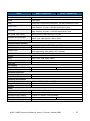
1.2. Specifications
μPAC-7186EX
PACs
CPU Specification
CPU
SRAM
Flash
EEPROM
NVRAM
RTC (Real Time Clock)
Hardware Serial Number
Build-in Watchdog Timer
Communication Interface
COM 1
COM 2
Ethernet Port
COM Port Formats
Data bit
Parity
Stop bit
Baud Rate
LED Display
5-digit 7-segment LED
System LED Indicator
Hardware Expansion
I/O expansion bus
User defined I/O pins
Operating Environment
Operating temperature
Storage Temperature
Humidity
Power
Protection
Frame Ground
Required Supply Voltage
Power Consumption
Dimensions
μPAC-7186EXD
80186 CPU, 80MHz or compatible
512K Bytes
512K Bytes
Erase unit is one sector (64K bytes); 100,000 erase/write cycles
16K Bytes
Data retention: 40 years; 1,000,000 erase/write cycles
31 Bytes
Battery backup, data valid up to 10 year
Year-2000 compliance; seconds, minutes, hours, date of
the month; month, year, valid up from 1980 to 2079
Yes
Yes
RS-232 (TXD, RXD, CTS, RTS and GND); Non-isolation
RS-485 (D2+, D2-; self-tuner ASIC inside); Non-isolation
10/100Base-TX Ethernet Controller
(Auto-negotiating, Auto_MDIX, LED indicator)
7, 8
None, Even, Odd, Mark, Space
1
115200 bps Max.
No
Yes
Yes
Yes
14 pins
-25°C to +75°C (-13°F to +167°F)
-40°C to +80°C (-40°F to +176°F)
5% to 95%, Non-condensing
Power reverse polarity protection
Yes (for ESD Protection)
+10VDC to +30VDC (non-regulated)
1.5W
2.5W
123mm x 72mm x 33mm
uPAC-7186EX Series User Manual, Version 1.0 beta1, October 2008
--- 11
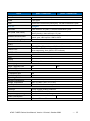
μPAC-7186EX-FD
PACs
CPU Specification
CPU
SRAM
Flash
NAND Flash
EEPROM
RTC (Real Time Clock)
Hardware Serial Number
Build-in Watchdog Timer
Communication Interface
COM 1
COM 2
Ethernet Port
COM Port Formats
Data bit
Parity
Stop bit
Baud Rate
LED Display
5-digit 7-segment LED
System LED Indicator
Hardware Expansion
I/O expansion bus
User defined I/O pins
Operating Environment
Operating temperature
Storage Temperature
Humidity
Power
Protection
Frame Ground
Required Supply Voltage
Power Consumption
Dimensions
μPAC-7186EXD-FD
80186 CPU, 80MHz or compatible
512K Bytes
512K Bytes
Erase unit is one sector (64K bytes); 100,000 erase/write cycles
64M Bytes
Data retention: 10 years; 100,000 erase/write cycles
16K Bytes
Data retention: 40 years; 1,000,000 erase/write cycles
31 Bytes
Battery backup, data valid up to 10 year
Year-2000 compliance; seconds, minutes, hours, date of the month;
month, year, valid up from 1980 to 2079
Yes
RS-232 (TXD, RXD, CTS, RTS and GND); Non-isolation
RS-485 (D2+, D2-; self-tuner ASIC inside); Non-isolation
10/100Base-TX Ethernet Controller
(Auto-negotiating, Auto_MDIX, LED indicator)
7, 8
None, Even, Odd, Mark, Space
1
115200 bps Max.
No
Yes
Yes
Yes
14 pins
-25°C to +75°C (-13°F to +167°F)
-40°C to +80°C (-40°F to +176°F)
5% to 95%, Non-condensing
Power reverse polarity protection
Yes (for ESD Protection)
+10VDC to +30VDC (non-regulated)
2W
2W
123mm x 72mm x 33mm
uPAC-7186EX Series User Manual, Version 1.0 beta1, October 2008
--- 12
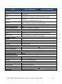
μPAC-7186EX-SD
PACs
CPU Specification
CPU
SRAM
Flash
Micro SD
EEPROM
RTC (Real Time Clock)
Hardware Serial Number
Build-in Watchdog Timer
Communication Interface
COM 1
COM 2
Ethernet Port
COM Port Formats
Data bit
Parity
Stop bit
Baud Rate
LED Display
5-digit 7-segment LED
System LED Indicator
Hardware Expansion
I/O expansion bus
User defined I/O pins
Operating Environment
Operating temperature
Storage Temperature
Humidity
Power
Protection
Frame Ground
Required Supply Voltage
Power Consumption
Dimensions
μPAC-7186EXD-SD
80186 CPU, 80MHz or compatible
512K Bytes
512K Bytes
Erase unit is one sector (64K bytes); 100,000 erase/write cycles
1G Bytes
16K Bytes
Data retention: 40 years; 1,000,000 erase/write cycles
31 Bytes
Battery backup, data valid up to 10 year
Year-2000 compliance; seconds, minutes, hours, date of the month;
month, year, valid up from 1980 to 2079
Yes
RS-232 (TXD, RXD, CTS, RTS and GND); Non-isolation
RS-485 (D2+, D2-; self-tuner ASIC inside); Non-isolation
10/100Base-TX Ethernet Controller
(Auto-negotiating, Auto_MDIX, LED indicator)
7, 8
None, Even, Odd, Mark, Space
1
115200 bps Max.
No
Yes
Yes
Yes
14 pins
-25°C to +75°C (-13°F to +167°F)
-40°C to +80°C (-40°F to +176°F)
5% to 95%, Non-condensing
Power reverse polarity protection
Yes (for ESD Protection)
+10VDC to +30VDC (non-regulated)
2W
2W
123mm x 72mm x 33mm
uPAC-7186EX Series User Manual, Version 1.0 beta1, October 2008
--- 13
μPAC-7186EX-SM
PACs
CPU Specification
CPU
SRAM
Flash
EEPROM
NVRAM
RTC (Real Time Clock)
Hardware Serial Number
Build-in Watchdog Timer
Communication Interface
COM 1
COM 2
Ethernet Port
COM Port Formats
Data bit
Parity
Stop bit
Baud Rate
LED Display
5-digit 7-segment LED
System LED Indicator
Hardware Expansion
I/O expansion bus
User defined I/O pins
Operating Environment
Operating temperature
Storage Temperature
Humidity
Power
Protection
Frame Ground
Required Supply Voltage
Power Consumption
Dimensions
μPAC-7186EXD-SM
80186 CPU, 80MHz or compatible
640K Bytes
16K Bytes
Data retention: 40 years; 1,000,000 erase/write cycles
31 Bytes
Battery backup, data valid up to 10 year
Year-2000 compliance; seconds, minutes, hours, date of the
month; month, year, valid up from 1980 to 2079
Yes
Yes
80186 CPU, 80MHz or compatible
RS-232 (TXD, RXD, CTS, RTS and GND); Non-isolation
RS-485 (D2+, D2-; self-tuner ASIC inside); Non-isolation
10/100Base-TX Ethernet Controller
(Auto-negotiating, Auto_MDIX, LED indicator)
7, 8
None, Even, Odd, Mark, Space
1
115200 bps Max.
No
Yes
Yes
Yes
14 pins
-25°C to +75°C (-13°F to +167°F)
-40°C to +80°C (-40°F to +176°F)
5% to 95%, Non-condensing
Power reverse polarity protection
Yes (for ESD Protection)
+10VDC to +30VDC (non-regulated)
2W
2W
123mm x 72mm x 33mm
uPAC-7186EX Series User Manual, Version 1.0 beta1, October 2008
--- 14
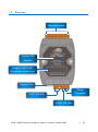
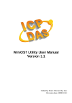
1.3. Overview
User define pins
System LED
indicator
5-digits 7-SEG LED
(for display version only)
Ethernet Port
Power
Connector
COM1 (RS-232)
COM2 (RS-485)
uPAC-7186EX Series User Manual, Version 1.0 beta1, October 2008
--- 15
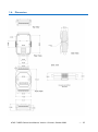
1.4. Dimension
uPAC-7186EX Series User Manual, Version 1.0 beta1, October 2008
--- 16
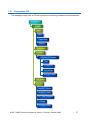
1.5. Companion CD
This package comes with a CD that includes the following software and documention:
CD: \Napdos
7186E
Demo
Basic
Framework
Xserver
Document
Firmware
VxComm_Firmware
Doc
Driver(PC)
OS_Image
Server(7186E)
OS_Image
PC_Tool
MiniOS7_Studio
MiniOS7_Utility
PC_Test_Program
PCDiag
Vxcomm_Utility
uPAC-7186EX Series User Manual, Version 1.0 beta1, October 2008
--- 17
2. Quick Start
This chapter provides users with basic information needed to begin using the
uPAC-7186EX.
2.1. Hardware installation
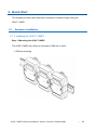
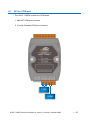
2.1.1. Installing the uPAC-7186EX
Step 1: Mounting the uPAC-7186EX
The uPAC-7186EX can either be mounted on DIN-rail or stack.
1: DIN-rail mounting
uPAC-7186EX Series User Manual, Version 1.0 beta1, October 2008
--- 18
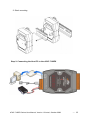
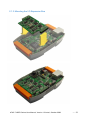
2: Stack mounting
Step 2: Connecting the Host PC to the uPAC-7186EX
uPAC-7186EX Series User Manual, Version 1.0 beta1, October 2008
--- 19
2.1.2. Mounting the I/O Expansion Bus
uPAC-7186EX Series User Manual, Version 1.0 beta1, October 2008
--- 20
2.1.3. Mounting the I/O Expansion Bus
uPAC-7186EX Series User Manual, Version 1.0 beta1, October 2008
--- 21
2.1.4. Wiring connections
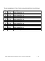
The pin assignment of 9-pin screw terminal block is as follows:
Pin
1
2
3
4
5
6
7
8
9
Name
CTS1
RTS1
RXD1
TXD1
INIT*
D2+
D2Vs+
GND
Description
CTS pin for COM1 (RS-232)
RTS pin for COM1 (RS-232)
RXD pin for COM1 (RS-232)
TXD pin for COM1 (RS-232)
Initial pin
DATA+ pin for COM2 (RS-485)
DATA- pin for COM2 (RS-485)
V+ of power supply (+10 to +30VDC, unregulated)
GND for the power supply
uPAC-7186EX Series User Manual, Version 1.0 beta1, October 2008
--- 22
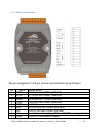
The pin assignment of top 14-pin screw terminal block is as follows:
Pin
10
11
12
13
14
15
16
17
18
19
20
21
22
23
Name
Pin 10
Pin 11
Pin 12
Pin 13
Pin 14
Pin 15
Pin 16
Pin 17
Pin 18
Pin 19
Pin 20
Pin 21
Pin 22
Pin 23
Description
User defined pin 10
User defined pin 11
User defined pin 12
User defined pin 13
User defined pin 14
User defined pin 15
User defined pin 16
User defined pin 17
User defined pin 18
User defined pin 19
User defined pin 20
User defined pin 21
User defined pin 22
User defined pin 23
uPAC-7186EX Series User Manual, Version 1.0 beta1, October 2008
--- 23
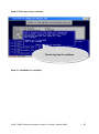
2.2. Software installation
All software resources are included on the companion CD, the following steps will
help you to install the resources and software from the companion CD.
Step 1: Copy the “Demo” folder from the companion CD to the Host PC
The folder is an essential resource for users developing custom programs which
contains libraries, header files, demo programs and more information as shown
below:
CD: \Napdos
7186EX
Demo
Basic
7K87K_for_COM
COM_Ports
..
.
Timer
Framework
FW_Demo01_Client
FW_Demo02_Server
..
.
Lib
Xserver
XDemo04_Basic
XDemo07_printCom1
..
.
XDemo14_7Seg_LED
Readme.txt
uPAC-7186EX Series User Manual, Version 1.0 beta1, October 2008
--- 24
Step 2: Install the MiniOS7 Utility
The MiniOS7 Utility is a tool that can be used to configure and upload files to the
controller and is located at:
CD:\Napdos\minios7\utility\minios7_utility\
ftp://ftp.icpdas.com/pub/cd/8000cd/napdos/minios7/utility/minios7_utility/
uPAC-7186EX Series User Manual, Version 1.0 beta1, October 2008
--- 25
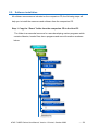
2.3. MiniOS7 Utility for downloading programs
Before you begin using the MiniOS7 Utility to download programs, ensure that
the controller is connected to the Host PC.
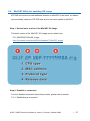
The download process has the following main steps: .
1. Establishing a connection
2. Download and executing programs on the controller
3. Making programs start automatically
All of these main steps will be described in detail later.
2.3.1. Establishing a connection between the Host PC and the uPAC-7186EX
Connect the Host PC to the uPAC-7186EX with the following connection types:
1. COM1 connection
2. LAN1 connection
Each of the connection types will be described in detail later.
uPAC-7186EX Series User Manual, Version 1.0 beta1, October 2008
--- 26
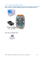
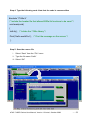
2.3.1.1.
Steps to use a COM1 connection
Step 1: Connect the uPAC-7186EX to the host PC using a COM1 connection
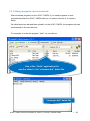
Step 2: Run the MiniOS7 Utility
uPAC-7186EX Series User Manual, Version 1.0 beta1, October 2008
--- 27
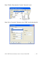
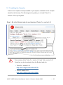
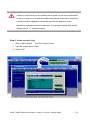
Step 3: Click the “New connection” from the “Connection” menu
Step 4: On the “Connection” dialog box, select “COM1” from the drop down list
uPAC-7186EX Series User Manual, Version 1.0 beta1, October 2008
--- 28
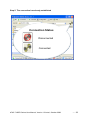
Step 5: The connection has already established
Connection Status
Disconnected
Connected
uPAC-7186EX Series User Manual, Version 1.0 beta1, October 2008
--- 29
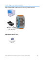
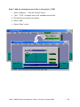
2.3.1.2.
Steps to use a LAN1 connection
Step 1: Connect uPAC-7186EX to the host PC using a LAN1 connection
Step 2: Run the MiniOS7 Utility
uPAC-7186EX Series User Manual, Version 1.0 beta1, October 2008
--- 30
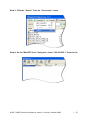
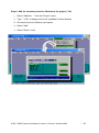
Step 3: Click the “Search” from the “Connection” menu
Step 4: On the “MiniOS7 Scan” dialog box, select “192.168.255.1” from the list
uPAC-7186EX Series User Manual, Version 1.0 beta1, October 2008
--- 31
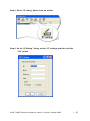
Step 5: Select “IP setting” button from the toolbar
Step 6: On the “IP Setting” dialog, set the “IP” settings and then click the
“Set” button
uPAC-7186EX Series User Manual, Version 1.0 beta1, October 2008
--- 32
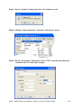
Step 7: On the “Confirm” dialog, click the “Yes” button to exit
Step 8: Click the “New connection” from the “Connection” menu
Step 9: On the “Connection” dialog box, select “TCP” from the drop down list
and enter the “IP” which just assigns
uPAC-7186EX Series User Manual, Version 1.0 beta1, October 2008
--- 33
Step 10: The connection has already established
Connection Status
Disconnected
Connected
uPAC-7186EX Series User Manual, Version 1.0 beta1, October 2008
--- 34
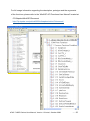
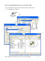
2.3.2. Uploading and executing programs on uPAC-7186EX
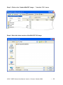
Step 1: On the host pc file list, Right click on the file name that you wish to
download and then select the “Upload” option
Host PC file list
Controller file list
Step 2: On the controller file list, Right click on the file name that you wish to
execute and then select the “Run” option
uPAC-7186EX Series User Manual, Version 1.0 beta1, October 2008
--- 35
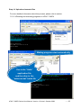
2.3.3. Making programs start automatically
After download programs on the uPAC-7186EX, if you need programs to start
automatically after the uPAC-7186EX start-up, it is easy to achieve it, to create a
batch
file called autoexec.bat and then upload it on the uPAC-7186EX, the program will start
automatically in the next start-up.
For example, to make the program “hello” run on start-up.
One is the “Hello” application file,
and the other is the “autoexec.bat” batch file
“autoexec.bat” batch file
uPAC-7186EX Series User Manual, Version 1.0 beta1, October 2008
--- 36
2.4. MiniOS7 Utility for updating OS image
ICP DAS will continue to add additional features to MiniOS7 in the future, we advise
you periodically check the ICP DAS web site for the latest update to MiniOS7.
Step 1: Get the latest version of the MiniOS7 OS image
The latest version of the MiniOS7 OS image can be obtain from:
CD:\ NAPDOS\7186e\OS_Image
http://ftp.icpdas.com/pub/cd/8000cd/napdos/7186e/OS_Image/
Step 2: Establish a connection
For more detailed information about this process, please refer to section
“2.3.1. Establishing a connection”.
uPAC-7186EX Series User Manual, Version 1.0 beta1, October 2008
--- 37
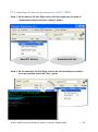
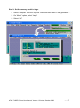
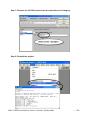
Step 3: Click on the “Update MiniOS7 Image …” from the “File” menu
Step 4: Select the latest version of the MiniOS7 OS image
uPAC-7186EX Series User Manual, Version 1.0 beta1, October 2008
--- 38
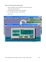
Step 5: Click on the “Update MiniOS7 Image …” from the “File” menu
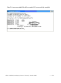
Step 6: Click on the “Info” buttion to check OS image version
uPAC-7186EX Series User Manual, Version 1.0 beta1, October 2008
--- 39
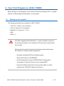
3. Your First Program on uPAC-7186EX
Before writing your first program, ensure that you have the necessary C/C++ compiler
and the corresponding functions library on your system.
3.1. Setting up the compiler
The following compilers are available for uPAC-7186EX.
Turbo C++ Version 1.01 (Freeware)
Turbo C Version 2.01 (Freeware)
Borland C++ Versions 3.1 - 5.2.x
MSC
MSVC ++
ICP DAS suggests that the Borland C++ version compiler is used as
the libraries provided on the companion CD have been created using
this compiler.
Special attention should be paid to the following items before using
the compiler to develop custom applications:
Generate a standard DOS executable program
Set the CPU option to 80188/80186
Set the floating point option to EMULATION if floating point
computation is required. (Be sure not to choose 8087)
Cancel the Debug Information function as this helps to reduce
program size. (MiniOS7 supports this feature.).
uPAC-7186EX Series User Manual, Version 1.0 beta1, October 2008
--- 40
3.1.1. Installing the Compiler
If there is no compiler currently installed on your system, installation of the compiler
should be the first step. The following section guides you to install Turbo C++
Version 1.01 on your system.
Step 1: Go to the Borland web site and download Turbo C++ version 1.01
Click here
Free versions of the Turbo C++ version 1.01 and Turbo version 2.01
Compilers can be downloaded from the Borland web site.
Turbo C++ version 1.01
http://dn.codegear.com/article/21751
Turbo C version 2.01
http://dn.codegear.com/article/20841
uPAC-7186EX Series User Manual, Version 1.0 beta1, October 2008
--- 41
Step 2: Unzip the downloaded zip file to the temporary folder
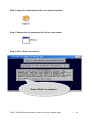
Step 3: Double click the executable file to start setup wizard
Step 4: Press “Enter” to continue
Press “Enter” to continue
uPAC-7186EX Series User Manual, Version 1.0 beta1, October 2008
--- 42
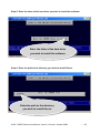
Step 5: Enter the letter of the hard drive you wish to install the software
Enter the letter of the hard drive
you wish to install the software
Step 6: Enter the path to the directory you wish to install files to
Enter the path to the directory
you wish to install files to
uPAC-7186EX Series User Manual, Version 1.0 beta1, October 2008
--- 43
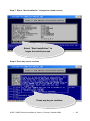
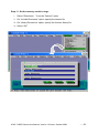
Step 7: Select “Start Installation” to begin the install process
Select “Start Installation” to
begin the install process
Step 8: Press any key to continue
Press any key to continue
uPAC-7186EX Series User Manual, Version 1.0 beta1, October 2008
--- 44
Step 9: Press any key to continue
Press any key to continue
Step 10: Installation is complete
uPAC-7186EX Series User Manual, Version 1.0 beta1, October 2008
--- 45
3.1.2. Setting up the environment variables
After installing the compiler, several compilers will be available from the Windows
Command line. You can set the path environment variable so that you can execute
This compiler on the command line by entering simple names, rather than by using
Their full path names.
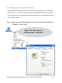
Step 1: Right click on the “My Computer” icon on your desktop and select the
“Properties” menu option
Right-click “My Computer”
and then select “Properties”
uPAC-7186EX Series User Manual, Version 1.0 beta1, October 2008
--- 46
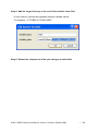
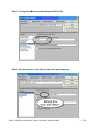
Step 2: On the “System Properties” dialog box, click the “Environment Variables”
button located under the “Advanced” sheet
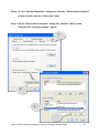
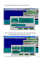
Step 3: On the “Environment Variables” dialog box, click the “Edit” button
located in the “System variables” option
1
2
3
uPAC-7186EX Series User Manual, Version 1.0 beta1, October 2008
--- 47
Step 4: Add the target directory to the end of the variable value field
A semi-colon is used as the separator between variable values.
For example, ”;c:\TC\BIN\;c:\TC\INCLUDE\”
Step 5: Restart the computer to allow your changes to take effect
uPAC-7186EX Series User Manual, Version 1.0 beta1, October 2008
--- 48
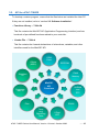
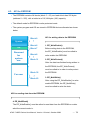
3.2. API for uPAC-7186EX
To develop a custom program, ensure that the files below are installed the Host PC.
If they are not installed, refer to “section 2.2. Software Installation”.
Functions Library ─ 7186e.lib
This file contains the MiniOS7 API (Application Programming Interface) and has
hundreds of pre-defined functions related to your controller.
Header File ─ 7186e.h
This file contains the forward declarations of subroutines, variables, and other
identifiers used for the MiniOS7 API.
COM
Ports
Others
(MISC)
EEPROM
Flash
Memory
Standard
IO
MiniOS7
API
Functions
Programm
-able IO
NVRAM
and
RTC
Files
SRAM
Timer
and
WatchDog
Timer
5-Digit
LED
uPAC-7186EX Series User Manual, Version 1.0 beta1, October 2008
--- 49
For full usage information regarding the description, prototype and the arguments
of the functions, please refer to the “MiniOS7 API Functions User Manual” located at:
CD:\Napdos\MiniOS7\Document
http://ftp.icpdas.com/pub/cd/8000cd/napdos/minios7/document/
uPAC-7186EX Series User Manual, Version 1.0 beta1, October 2008
--- 50
3.3. Build and run your first program
If you don‟t using the TC++ (Turbo C++) to write a program, please take the following
steps.
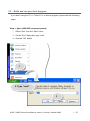
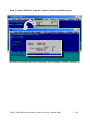
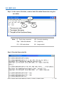
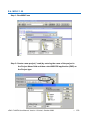
Step 1: Open a MS-DOS command prompt
i.
Select “Run” from the “Start” menu
ii. On the “Run” dialog box, type “cmd”
iii. click the “OK” button
1
2. Type “cmd”
3
uPAC-7186EX Series User Manual, Version 1.0 beta1, October 2008
--- 51
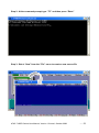
Step 2: At the command prompt, type “TC” and then press “Enter”
Step 3: Select “New” from the “File” menu to create a new source file
uPAC-7186EX Series User Manual, Version 1.0 beta1, October 2008
--- 52
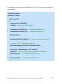
Step 4: Type the following code. Note that the code is case-sensitive
#include “7186e.h”
/* Include the header file that allows 8000e.lib functions to be used */
void main(void)
{
InitLib(); /* Initiate the 7186e library */
Print(“Hello world!\r\n”); /* Print the message on the screen */
}
Step 5: Save the source file
i.
Select “Save” from the “File” menu
ii. Type the file name “Hello”
iii. Select “OK”
uPAC-7186EX Series User Manual, Version 1.0 beta1, October 2008
--- 53
If there is a text editor you are familiar with or prefer to use such as Notepad
or edit, you may use it to write the code shown above. It should be noted that
a word processor application cannot be used for this purpose, as the
application must save the file as plain text. C language program files should
always have a “.C” extension name.
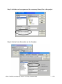
Step 6: Create a project (*prj)
i.
Select “Open project…” from the “Project” menu
ii. Type the project name “Hello”
iii. Select “OK”
uPAC-7186EX Series User Manual, Version 1.0 beta1, October 2008
--- 54
Step 7: Add the necessary source files to the project (*.CPP)
i.
Select “Add item…” from the “Project” menu
ii. Type “ *.CPP ” to display a list of all available source files
iii. Choose the source files you require
iv. Select “Add”
v. Select “Done” to exit
uPAC-7186EX Series User Manual, Version 1.0 beta1, October 2008
--- 55
Step 8: Add the necessary function libraries to the project (*.lib)
i.
Select “Add item…” from the “Project” menu
ii. Type “ *.LIB ” to display a list of all available function libraries
iii. Choose the function libraries you require
iv. Select “Add”
v. Select “Done” to exit
uPAC-7186EX Series User Manual, Version 1.0 beta1, October 2008
--- 56
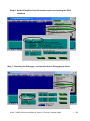
Step 9: Set the memory model to large
i.
Select “Compiler” from the “Options” menu and then select “Code generation…”
ii. On “Model” option, select “Large”
iii. Select “OK”
uPAC-7186EX Series User Manual, Version 1.0 beta1, October 2008
--- 57
Step 10: Set the memory model to large
i.
Select “Compiler” from the “Options” menu and then select
“Advanced code generation…”
ii. On “Floating Point” option, select “Emulation”
iii. On “Instruction Set” option, select “80186”
iv. Select “OK”
uPAC-7186EX Series User Manual, Version 1.0 beta1, October 2008
--- 58
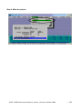
Step 11: Set the memory model to large
i.
Select “Directories…” from the “Options” menu
ii. On “Include Directories” option, specify the header file
iii. On “Library Directories” option, specify the function library file
iv. Select “OK”
uPAC-7186EX Series User Manual, Version 1.0 beta1, October 2008
--- 59
Step 12: Select “Build all” from the “Compile” menu to build the project
uPAC-7186EX Series User Manual, Version 1.0 beta1, October 2008
--- 60
Step 13: Use the MiniOS7 Utility to connect the uPAC-7186EX
For more detailed information about this process, please refer to section
“2.3.1. Establishing a connection”.
uPAC-7186EX Series User Manual, Version 1.0 beta1, October 2008
--- 61
Step 14: Upload and execute files
For more detailed information about this process, please refer to section
“2.3.2. UPloading and executing programs on uPAC-7186EX
Making programs start automatically
One is the “Hello”
application file,
and the other is the
“autoexec.bat” batch file
uPAC-7186EX Series User Manual, Version 1.0 beta1, October 2008
--- 62
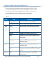
4. API and Demo Program Reference
There are several demo programs that have been designed for uPAC-7186EX.
You can examine the demo source code, which includes numerous comments,
to familiarize yourself with the MiniOS7 API, This will allow to quickly develop
your own applications quickly by modifying these demo programs.
Basic
Folder
File
Hello
Demo
Explanation
Config_1_Basic
Reads information from a text file (basic).
Config_2_Advanced
Reads a config file (text file)(advanced).
Hello_C
Reads the library version and flash memory size.
Hello_C++
Misc
Reset
Resets the software.
Runprog
Illustrates how to select an item and run it.
Serial
Illustrates how to retrieve 64-bit hardware unique
serial number.
Watchdog
Enables the WDT or bypasses the enable
WatchDog function.
Smmi
SystemKey
Shows how to operate the systemkey function
simply and easily.
Led
Shows how to control the red LED and 7-segment
display.
Memory
S256
Shows how to read or write to the 256K byte
battery backup.
uPAC-7186EX Series User Manual, Version 1.0 beta1, October 2008
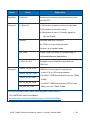
--- 63
Folder
DateTime
Demo
DateTime
Explanation
Shows how to read and write the date and time
from the RTC.
Com port
C_Style_IO
(1) Shows how to write a function to input data.
(2) Shows how to receive a string.
(3) Shows how to use a C function: sscanf or
just use Scanf()
Receive
Receives data from COM port.
Slv_COM.c is in non-blocked mode
Receive.c is in blocked mode.
Slv_COM
A slave COM Port demo for (request/reply) or
(command/response) applications.
ToCom_In_Out
Illustrates how to Read/Write byte data via
COM Port.
Com port
7K87K_DI_for_Com
7K87K_DO_for_Com
"COM Port" can be used to connect and
control i-7k or i-87k series modules.
For uPAC-7186EX module and can use, COM2,
7K87K_AI_for_Com
COM3.
AO_22_26_for_Com
AO_024_for_Com
For uPAC-7186EX module and (CPU 40 and
80M) can use, COM3, COM4.
For more information about these demo programs, please refer to:
CD:\ NAPDOS\7186e\ Demo\Basic\
http://ftp.icpdas.com/pub/cd/8000cd/napdos/7186e/Demo/Basic/
uPAC-7186EX Series User Manual, Version 1.0 beta1, October 2008
--- 64
4.1. API for COM port
The uPAC-7186EX include two COM ports
1. MiniOS7 COM port functions
2. (C style) Standard COM port functions
COM1
COM2
uPAC-7186EX Series User Manual, Version 1.0 beta1, October 2008
--- 65
4.1.1. Types of COM port functions
There are two types of functions below for using COM port.
1. MiniOS7 COM port functions
2. (C style) Standard COM port functions
You have the alternative of MiniOS7 COM ports functions or (C style)
Standard COM port functions. If you choose the ones, then the another
can not be used.
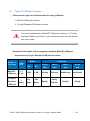
Summarize the results of the comparison between MiniOS7 COM port
functions and (C style) Standard COM port functions:
Kinds of
Functions
MiniOS7
COM port
Buffer
COM
Port
0, 1,
2, etc.
(C style)
Standard
COM port
1
(Note)
RX
TX
1 KB
1 KB
512
256
Bytes
Bytes
Functions
Check
Send
Read
Show
data
data
data
data
IsCom()
ToCom()
ReadCom()
printCom()
Getch()
Print()
Kbhit()
Puts()
Putch()
uPAC-7186EX Series User Manual, Version 1.0 beta1, October 2008
--- 66
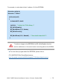
4.1.2. API for MiniOS7 COM port
API for using COM ports
1. InstallCom()
Before any COM Port can be used, the driver must be installed by calling
InstallCom().
2. AddCom2fun()
Before using COM2, the AddCom2fun() must be called to work for uPAC-7186EX.
3. RestoreCom()
If the program calls InstallCom(), the RestoreCom()must be called to restore the
COM Port driver.
API for checking if there is any data in the COM port input buffer
4. IsCom()
Before reading data from COM port, the IsCom() must be called to check whether
there is any data currently in the COM port input buffer.
API for reading data from COM ports
5. ReadCom()
After IsCom() confirms that the input buffer contains data, the ReadCom() must be
called to read the data from the COM port input buffer.
uPAC-7186EX Series User Manual, Version 1.0 beta1, October 2008
--- 67
API for sending data to COM ports
6. ToCom()
Before sending data to COM ports, the ToCom() must be called to send data to
COM ports.
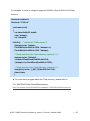
For example, reading and receiving data through the COM1:
#include <stdio.h>
#include “7186e.h”
void main(void)
{
int quit=0, data;
InitLib(); /* Initiate the 7186e library */
InstallCom(1, 115200, 8, 0, 1); /* Install the COM1 driver */
while(!quit)
{
if(IsCom(1)) /* Check if there is any data in the COM port input buffer */
{
data=ReadCom(1); /* Read data from COM1 port */
ToCom(1, data); /* Send data via COM1 port */
if(data==’q’) quit=1; /* If „q‟ is received, exit the program */
}
}
RestoreCom(1); /* Uninstall the COM1 driver */
}
uPAC-7186EX Series User Manual, Version 1.0 beta1, October 2008
--- 68
API for showing data from COM ports
7. printCom()
Functions such as printfCom() in the C library allow data to be output from
COM ports.
For example, showing data from the COM1 port:
#include <stdio.h>
#include “7186e.h”
void main(void)
{
int i;
/* Initiate the 7186e library */
InitLib();
InstallCom(1, 115200, 8, 0, 1); /* Install the COM1 driver */
for (i=0;i<10;i++)
{
printCom(1,”Test %d\n\r”, i);
}
Delay(10); /* Wait for all data are transmitted to COM port */
RestoreCom(1);
}
► For more demo program about the COM port, please refer to:
CD:\ NAPDOS\7186e\ Demo\Basic\com_port
http://ftp.icpdas.com/pub/cd/8000cd/napdos/7186e/Demo/Basic/com_port
uPAC-7186EX Series User Manual, Version 1.0 beta1, October 2008
--- 69
4.1.3. API for standard COM port
The standard COM port is used to download program from PC to the
uPAC-7186EX.
The following configurations of the standard COM port are fixed:
Baudrate=115200 bps, Data format=8 bits
Parity check=none, Start bit=1, Stop bit=1
API for checking if there is any data in the input buffer
1. Kbhit()
Before reading data from standard I/O port, the kbhit() must be called to check
whether there is any data currently in the input buffer.
API for reading data from standard I/O port
2. Getch()
After kbhit() confirms that the input buffer contains data, the Getch() must be called
to read data from the input buffer.
API for sending data to standard I/O port
3. Puts() – For sending a string
Before sending data to standard I/O port, the Puts() must be called to send data to
COM Port.
uPAC-7186EX Series User Manual, Version 1.0 beta1, October 2008
--- 70
4. Putch( ) – For sending one character
Before sending data to standard I/O port, the Putch() must be called to send data to
COM Port.
API for showing data from standard I/O port
5. Print()
Functions such as Print() in the C library allow data to be output from the COM Port.
For example, reading and receiving data through COM1:
#include<stdio.h>
#include “7186e.h”
void main(void)
{
int quit=0, data;
InitLib(); /* Initiate the 7186e library */
while(!quit)
{
if(Kbhit()) /* Check if any data is in the input buffer */
{
data=Getch(); /* Read data from COM1 */
Putch(data); /* Send data to COM1 */
if(data==’q’) quit=1; /* If „q‟ is received, exit the program */
}
}
}
uPAC-7186EX Series User Manual, Version 1.0 beta1, October 2008
--- 71
For example, showing data through COM1:
#include <stdio.h>
#include “7186e.h”
void main(void)
{
int i;
/* Initiate the 7186e library */
InitLib();
for(i=0;i<10;i++)
{
Print(“Test %d\n\r”,i);
}
}
uPAC-7186EX Series User Manual, Version 1.0 beta1, October 2008
--- 72
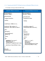
4.1.4. Comparing with MiniOS7 COM port function and Standard COM port function
For example, learning to show the ASCII code:
MiniOS7 COM port functions
Standard COM port functions
#include<stdio.h>
#include “7186e.h”
#include<stdio.h>
#include “7186e.h”
void main(void)
{
unsigned char item;
void main(void)
{
unsigned char item;
InitLib();
InitLib();
InstallCom(1, 115200, 8, 0, 1);
printCom(1,”Hits any key.\n”);
printCom(1,”Hit the ESC to exit!\n”);
for(;;)
{
if(IsCom(1))
{
item=ReadCom(1);
if(item==’q’)
{
return;
}
else
{
printCom(1,”----------\n\r”);
printCom(1,”char:”);
ToCom(1,item);
printCom(1,"\n\rASCII(%c)\n\r”,item)
;
printCom(1,“Hex(%02X)\n\r”,item);
}
}
}
Delay(10);
RestoreCom(1);
}
Print("Hits any key.\n");
Print("Hits the ESC to exit !\n");
for(;;)
{
if(kbhit())
{
item=Getch();
if(item==’q’)
{
return;
}
else
{
Print(”----------\n\r”);
Print(“char:“);
Putch(item);
Print("\n\rASCII(%c)\n\r”,item);
Print(“Hex(%02X)\n\r”,item);
}
}
}
}
uPAC-7186EX Series User Manual, Version 1.0 beta1, October 2008
--- 73
4.1.5. Request/Response protocol define on COM port
Request/Response communication is very typical protocol architecture, if you want
to design a command set of communication protocol as table below, you can refer to
“slave_com” demo.
For a request/response application,
please refer to “slave_com” demo
Request
Response
Request
Response
GetCounter
>1234
SetDO1
>OK
ResetDO2
>OK
GetVersion
>V1.0.0
For more demo program about the COM port, please refer to:
CD:\ NAPDOS\7186e\ Demo\Basic\com_port
http://ftp.icpdas.com/pub/cd/8000cd/napdos/7186e/Demo/Basic/com_port
uPAC-7186EX Series User Manual, Version 1.0 beta1, October 2008
--- 74
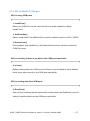
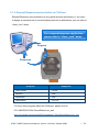
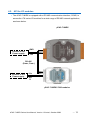
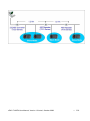
4.2. API for I/O modules
The uPAC-7186EX is equipped with a RS-485 communication interface, COM2, to
access the i-7K series I/O modules for a wide range of RS-485 network application,
as shown below.
μPAC-7186EX
GND
Connect to the
Power supply
DATADATA
+
+Vs
RS-485
(Data+, Data-)
Connect to the
Power supply
+Vs
DATA
+
DATA-
GN
D
μPAC-7186EX/i-7000 modules
uPAC-7186EX Series User Manual, Version 1.0 beta1, October 2008
--- 75
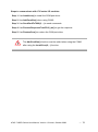
Steps to communicate with i-7K series I/O modules:
Step 1: Use Installcom() to install the COM port driver.
Step 2: Use AddCom2fun() when using COM2
Step 3: Use SendCmdTo7000(0,…) to send commands
Step 4: Use ReceiveResponseFrom7000_ms() to get the response.
Step 5: Use RestoreCom() to restore the COM port driver
The AddCom2fun() function must be called when using the COM2
after using the InstallCom(2,…) function.
uPAC-7186EX Series User Manual, Version 1.0 beta1, October 2008
--- 76
For example, to send a command „$00M‟ to slot 7‟s i-7K I/O module for getting the
module name:
#include <stdio.h>
#include “7186e.h”
void main(void)
{
unsigned char InBuf0[60];
InitLib(); /* Initiate the 7186e library */
InstallCom(1,115200,8,0,1); /* Install the COM1 driver */
InstallCom(2,115200,8,0,1); /* Install the COM2 driver */
AddCom2fun();
SendCmdTo7000(2,”$00M”,0); /* Send a command to COM2 */
/* Timeout = 50ms, check sum disabled */
ReceiveResponseFrom7000_ms(2,InBuf0,50,0);
printCom(1,”Module Name = %s”, InBuf0);
Delay(10); /* Wait for all data are transmitted to COM port */
RestoreCom(1); /* Uninstall the COM1 driver */
RestoreCom(2); /* Uninstall the COM2 driver */
}
uPAC-7186EX Series User Manual, Version 1.0 beta1, October 2008
--- 77
4.3. API for EEPROM
The EEPROM contains 64 blocks (block 0 ~ 63), and each block has 256 bytes
(address 0 ~ 255), with a total size of 16,384 bytes (16K) capacity.
The default mode for EEPROM is write-protected mode.
The system program and OS are stored in EEPROM that are allocated as shown
below.
Block 0
OS
Block 6
1. EE_WriteEnable()
Block 7
Before writing data to the EEPROM,
the EE_WriteEnable() must be called to
Block 8
write-enable the EEPROM.
~
Reserved
for
system
use
~
System
API for writing data to the EEPROM
Block 31
2. EE_WriteProtect()
After the data has finished being written to
the EEPROM, the EE_WriteProtect()
must be called to in order to write-protect
Block 32
~
For user
Block 63
the EEPROM.
3. EE_MultiWrite()
After using the EE_WriteEnable() to writeenable EEPROM, the EE_MultiWrite()
must be called to write the data.
API for reading data from the EEPROM
4. EE_MultiRead()
The EE_WriteEnable() must be called to read data from the EEPROM no matter
what the current mode is.
uPAC-7186EX Series User Manual, Version 1.0 beta1, October 2008
--- 78
For example, to write data to block1, address 10 of the EEPROM:
#include <stdio.h>
#include “7186e.h”
void main(void)
{
int data=0x55, data2;
InitLib(); /* Initiate the 7186e library */
EE_WriteEnable();
EE_MultiWrite(1,10,1,&data);
EE_WriteProtect();
EE_MultiRead(1,10,1,&data2); /* Now data2=data=0x55 */
}
To write an integer to the EEPROM, the EE_WriteEnable() function
must be called twice, in the same manner as writing data to the NVRAM
► For more demo program about the EEPROM, please refer to:
CD:\ NAPDOS\7186e\ Demo\Basic\memory
http://ftp.icpdas.com/pub/cd/8000cd/napdos/7186e/demo/basic/memory
uPAC-7186EX Series User Manual, Version 1.0 beta1, October 2008
--- 79
4.4. API for Flash Memory
Free: 448 K bytes
The uPAC-7186EX module contains 512K
bytes of Flash memory.
MiniOS7 uses the last 64K bytes, the other
MiniOS7: 64 K bytes
Total Size: 512 K bytes
parts of the memory are used to store user
programs or data.
0 x 8000
Free
0 x 9000
Each bit of the Flash memory only can be
written from 1 to 0 and cannot be written
Free
from 0 to 1.
0 x A000
Free
Before any data can be written to the Flash
memory, the flash must be erased first,
Free
0 x B000
which returns all data to 0xFF, meaning that
all data bits are set to “1”. Once their is
Free
Free
0 x C000
completed, new data can be written.
0 x D000
API for writing data to the Flash Memory
Free
0 x E000
1. FlashWrite()
MiniOS7
0 x F000
The FlashWrite() must be called to write
data to the Flash Memory.
API for reading data from the Flash Memory
2. FlashRead()
The FlashRead() must be called to read data from the Flash Memory.
uPAC-7186EX Series User Manual, Version 1.0 beta1, October 2008
--- 80
For example, to write an integer to segment 0xD000, offset 0x1234 of the Flash
memory:
#include <stdio.h>
#include “7186e.h”
void main(void)
{
int data=0xAA55, data2;
char *dataptr;
int *dataptr2;
InitLib(); /* Initiate the 7186e library */
dataptr=(char *)&data;
FlashWrite(0xd000,0x1234, *dataptr++);
FlashWrite(0xd000,0x1235, *dataptr);
/* Read data from the Flash Memory (method 1) */
dataprt=(char *)&data2;
*dataptr=FlashRead(0xd000,0x1234);
*(dataptr+1)=FlashRead(0xd000,0x1235);
/* Read data from the Flash Memory (method 2) */
dataptr2=(int far *)_MK_FP(0xd000,0x1234);
data=*data;
}
► For more demo program about the Flash memory, please refer to:
CD:\ NAPDOS\7186e\ Demo\Basic\memory
http://ftp.icpdas.com/pub/cd/8000cd/napdos/7186e/Demo/Basic/memory
uPAC-7186EX Series User Manual, Version 1.0 beta1, October 2008
--- 81
4.5. API for NVRAM and RTC
The uPAC-7186EX is equipped with an RTC (Real Time Clock), and 31 bytes
of NVRAM memory can be used to store data.
NVRAM is the same as SRAM, but it uses a battery to retain the data, so the data.
store in the NVRAM is not lost when the module is powered off and can be used for
10 years.
NVRAM has no limit on the number of times the data can be written.
(Both Flash and EEPROM both have a limit on the numbers of data can be
re-written.)
API for writing data to the NVRAM
1. WriteNVRAM()
The WriteNVRAM() must be called in order to write data to the NVRAM.
API for reading data from the NVRAM
2. ReadNVRAM()
The ReadNVRAM() must be called in order to write data to the NVRAM.
uPAC-7186EX Series User Manual, Version 1.0 beta1, October 2008
--- 82
For example, use the following code to write data to the NVRAM address 0:
#include <stdio.h>
#include “7186e.h”
void main(void)
{
int data=0x55, data2;
InitLib(); /* Initiate the 7186e library */
WriteNVRAM(0,data);
data2=ReadNVRAM(0); /* Now data2=data=0x55 */
}
For example, the following can be used to write an integer (two bytes) to NVRAM:
#include <stdio.h>
#include “7186e.h”
void main(void)
{
int data=0xAA55, data2;
char *dataptr=(char *)&data;
InitLib(); /* Initiate the 7186e library */
WriteNVRAM(0, *dataptr); /* Write the low byte */
WriteNVRAM(1, *dataptr+1); /* Write the high byte */
dataptr=(char *) &data2;
*dataptr=ReadNVRAM(0); /* Read the low byte */
(*dataptr+1)=ReadNVRAM(1); /* Read the high byte */
}
► For more demo program about the NVRAM and RTC, please refer to:
CD:\ NAPDOS\7186e\Demo\Basic\memory
http://ftp.icpdas.com/pub/cd/8000cd/napdos/7186e/Demo/Basic/memory
uPAC-7186EX Series User Manual, Version 1.0 beta1, October 2008
--- 83
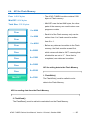
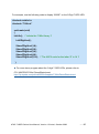
4.6. API for 5-Digit LED
The uPAC-7186EX contains a 5-Digit 7-SEG LED with a decimal point on the
left-hand side of each digit, which be used to display numbers, IP addresses, time,
and so on.
API for controlling the 5-Digit 7-SEG LED
1. Init5DigitLed()
Before using any LED functions, the Init5DigitLed() must be called to initialize the
5-Digit 7-SEG LED.
API for displaying a message on the 5-Digit 7-SEG LED
2. Show5DigitLed()
After the Init5DigitLed() is used to initialize the 5-Digit 7-SEG LED, the
Show5DigitLed() must be called to display information on the 5-Digits 7-SEG LED.
uPAC-7186EX Series User Manual, Version 1.0 beta1, October 2008
--- 84
For example, use the following code to display “8000E” on the 5-Digit 7-SEG LED:
#include <stdio.h>
#include “7186e.h”
void main(void)
{
InitLib(); /* Initiate the 7186e library */
Init5DigitLed();
Show5DigitLed(1,8);
Show5DigitLed(2,0);
Show5DigitLed(3,0);
Show5DigitLed(4,0);
Show5DigitLed(5,14); /* The ASCII code for the letter „E‟ is 14 */
}
► For more demo program about the 5-digit 7-SEG LEDs, please refer to:
CD:\ NAPDOS\7186e\ Demo\Basic\smmi
http://ftp.icpdas.com/pub/cd/8000cd/napdos/7186e/Demo/Basic/smmi
uPAC-7186EX Series User Manual, Version 1.0 beta1, October 2008
--- 85
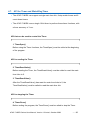
4.7. API for Timer and WatchDogTimer
The uPAC-7186EX can support a single main time tick, 8 stop watch timers and 8
count down timers.
The uPAC-7186EX uses a single 16-bit timer to perform these timer functions, with
a timer accuracy of 1 ms..
API that can be used to control the Timer
1. TimerOpen()
Before using the Timer functions, the TimerOpen() must be called at the beginning
of the program.
API for reading the Timer
2. TimerResetValue()
Before reading the Timer, the TimerResetValue() must be called to reset the main
time ticks to 0.
3. TimerReadValue()
After the TimerResetValue() has reset the main time ticks to 0, the
TimerReadValue() must be called to read the main time tick.
API for stopping the Timer
4. TimerClose()
Before ending the program, the TimerClose() must be called to stop the Timer.
uPAC-7186EX Series User Manual, Version 1.0 beta1, October 2008
--- 86
For example, the following code can be used to read the main time ticks from 0:
#include <stdio.h>
#include “7186e.h”
void main(void)
{
Unsigned long time iTime;
InitLib(); /* Initiate the 7186e library */
TimerOpen();
While(!quit)
{
If(Kbhit())
TimerResetValue(); /* Reset the main time ticks to 0 */
iTime=TimerReadValue(); /* Read the main time ticks from 0 */
}
TimerClose(); /* Stop using the 8000e timer function */
}
► For more demo program about the timer, please refer to:
CD:\ NAPDOS\7186e\ Demo\Basic\timer
http://ftp.icpdas.com/pub/cd/8000cd/napdos/7186e/Demo/Basic/timer
uPAC-7186EX Series User Manual, Version 1.0 beta1, October 2008
--- 87
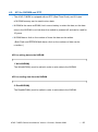
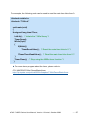
4.8. API for WatchDog Timer (WDT)
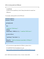
The default WatchDog timer (WDT) value for the uPAC-7186EX module is fixed at
0.8 seconds for MiniOS7 version 2.0.
When the uPAC-7186EX is first powered on, the WatchDog Timer will always be
enabled.
The MiniOS7 for the uPAC-7186EX will automatically refresh the WatchDog Timer
after being powered on. The software driver can be called by a user program to
prevent the MinOS7 from refreshing the WatchDog Timer.
API for refreshing WDT
1. EnableWDT()
The WDT is always enabled, before user‟s programming to refresh it, the
EnableWDT() must be called to stop refreshing WDT.
2. RefreshWDT()
After EnableWDT() stop refreshing WDT, the RefreshWDT() must be called to
refresh the WDT.
3. DisableWDT()
After user‟s programming to refresh WDT, the DisableWDT() should be called to
automatically refresh the WDT.
uPAC-7186EX Series User Manual, Version 1.0 beta1, October 2008
--- 88
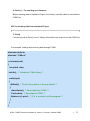
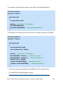
For example, to refresh the Watchdog Timer:
#include <stdio.h>
#include “7186e.h”
void main(void)
{
Unsigned long time iTime;
InitLib(); /* Initiate the 7186e library */
Enable WDT();
While(!quit)
{
RefreshWDT();
User_function();
}
DisableWDT();
}
► For more demo program about the WatchDog Timer, please refer to:
CD:\ NAPDOS\7186e\ Demo\Basic\Misc
http://ftp.icpdas.com/pub/cd/8000cd/napdos/7186e/Demo/Basic/Misc
uPAC-7186EX Series User Manual, Version 1.0 beta1, October 2008
--- 89
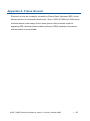
Appendix A. Frame Ground
Electronic circuits are constantly vulnerable to Electro-Static Discharge (ESD), which
become worse in a continental climate area. Some I-7000 ,M-7000 and I-8000 series
modules feature a new design for the frame ground, which provides a path for
bypassing ESD, allowing enhanced static protection (ESD) capability and ensures
that the module is more reliable.
uPAC-7186EX Series User Manual, Version 1.0 beta1, October 2008
--- 90
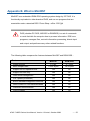
Appendix B. What is MiniOS7
MiniOS7 is an embedded ROM-DOS operating system design by ICP DAS. It is
functionally equivalent to other brands of DOS, and can run programs that are
executable under a standard DOS. Photo Shop + office 2007yji4
DOS (whether PC-DOS, MS-DOS or ROMDOS) is a set of commands
or code that tells the computer how to process information. DOS runs
programs, manages files, controls information processing, directs input
and output, and performs many other related functions.
The following table compares the features between MiniOS7 and ROM-DOS:
Feature
MiniOS7
ROM-DOS
0.1 sec
4 ~ 5 sec
< 64 K bytes
64 K bytes
Support for I/O expansion bus
Yes
No
Support for ASIC key
Yes
No
Flash ROM management
Yes
No
O.S. update (Download)
Yes
No
Built-in hardware diagnostic functions
Yes
No
Direct control of 7000 series modules
Yes
No
Customer ODM functions
Yes
No
Free of charge
Yes
No
Power-up time
More compact size
uPAC-7186EX Series User Manual, Version 1.0 beta1, October 2008
--- 91
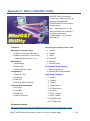
Appendix C. What is MiniOS7 Utility
MiniOS7 Utility is a tool for
configuring, uploading files to all
products embedded with
ICPDAS MiniOS7 with easiness
and quickness.
Note:Since version 3.1.1, the
Utility can allow users remotely
access the controllers
(7188E,8000E,…ect) through
the Ethernet
Functions
Supported connection ways
Including Frequently Used Tools
a. 7188XW
1. COM port connection (RS-232)
b. 7188EU
2. Ethernet connection (TCP & UDP)
c. 7188E
(Supported since version 3.1.1)
Maintenance
1. Upload file(s)
2. Delete file(s)
3. Update MiniOS7 image
Configuration
1. Date and Time
d. SendTCP
e. Send232
f. VxComm Utility
PC System Requirements
1. IBM compatible PC
2. Windows 95 /98/NT/2000/XP
Supported Products
2. IP address
1. 7188XA
3. COM port
2. 7188XB
4. Disk size (Disk A, Disk B)
3. 7188XC
Check product information
4. 7188EX series
1. CPU type
5. All i-8000 series
2. Flash Size
6. iView100
3. SRAM Size
7. uPAC-7186XB
4. COM port number
8. uPAC-7186EX
9. ET-6000 series
10. ET-7000 series
Download location:
http://ftp.icpdas.com.tw/pub/cd/8000cd/napdos/minios7/utility/minios7_utility/
uPAC-7186EX Series User Manual, Version 1.0 beta1, October 2008
--- 92
Appendix D. What is VxComm Utility
uPAC-7186EX Series User Manual, Version 1.0 beta1, October 2008
--- 93
Appendix E. More C Compiler Settings
This section describes the setting of the following compilers:
Turbo C 2.01 Compiler
BC++ 3.1 IDE
MSC 6.00 Compiler
MSVC 1.50 Compiler
E.1. Turbo C 2.01
You have a couple of choices here, you can:
1:Using a command line
For more information, please refer to
CD:\8000\NAPDOS\8000\841x881x\Demo\hello\Hello_C\gotc.bat
tcc -Ic:\tc\include -Lc:\tc\lib hello1.c ..\..\lib\8000e.lib
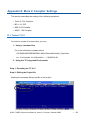
2:Using the TC Integrated Environment
Step 1: Executing the TC 2.01
Step 2: Editing the Project file
Adding the necessary library and file to the project
uPAC-7186EX Series User Manual, Version 1.0 beta1, October 2008
--- 94
Step 3: Save the project and entering a name, such as LED.prj
Step 4: Load the Project
Step 5: Change the Memory model (Large for 8000e.lib) and set the Code
Generation to 80186/80286
uPAC-7186EX Series User Manual, Version 1.0 beta1, October 2008
--- 95
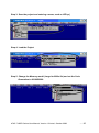
Step 6: Building the project
uPAC-7186EX Series User Manual, Version 1.0 beta1, October 2008
--- 96
E.2. BC++ 3.1. IDE
Step 1: Executing the Borland C++ 3.1
Step 2: Creating a new project file (*.prj)
Step 3: Add all the necessary files to the project
uPAC-7186EX Series User Manual, Version 1.0 beta1, October 2008
--- 97
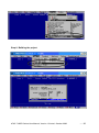
Step 4: Change the Memory model (Large for 8000e.lib)
Step 5: Set the Advanced code generation options and Set the Floating
Point to Emulation and the Instruction Set to 80186
uPAC-7186EX Series User Manual, Version 1.0 beta1, October 2008
--- 98
Step 6: Set the Entry/Exit Code Generation option and setting the DOS
standard
Step 7: Choosing the Debugger…and set the Source Debugging to None
uPAC-7186EX Series User Manual, Version 1.0 beta1, October 2008
--- 99
Step 8: Make the project
uPAC-7186EX Series User Manual, Version 1.0 beta1, October 2008
--- 100
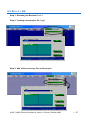
E.3. MSC 6.00
Step 1: In the source file folder, create a batch file called Gomsc.bat using the
text editor
Note::/C Don't strip comments
/GS No stack checking
/Fpa:Calls with altmath
/Fm [map file]
/G1:186 instructions
/AL Large model
Step 2: Run the Gomsc.bat file
uPAC-7186EX Series User Manual, Version 1.0 beta1, October 2008
--- 101
Step 3: A new executable file will be created if it is successfully compiled
uPAC-7186EX User Manual, Version 1.0 beta1, October 2008
--- 102
E.4. MSVC 1.50
Step 1: Run MSVC.exe
Step 2: Create a new project (*.mak) by entering the name of the project in
the Project Name field and then select MS-DOS application (EXE) as
the Project type
uPAC-7186EX User Manual, Version 1.0 beta1, October 2008
--- 103
Step 3: Add the user's program and the necessary library files to the project
Step 4: Set the Code Generation on the Compiler.
uPAC-7186EX User Manual, Version 1.0 beta1, October 2008
--- 104
Step 5: Change the Memory model (large for 8000e.lib)
Step 6: Remove the xcr, afxcr library from the Input Category
uPAC-7186EX User Manual, Version 1.0 beta1, October 2008
--- 105
Step 7: Remove the OLOGO option from the miscellancous Category.
Step 8: Rebuild the project
uPAC-7186EX User Manual, Version 1.0 beta1, October 2008
--- 106
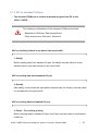
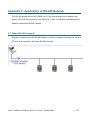
Appendix F. Application of RS-485 Network
The RS-485 length can be up to 4000 ft or 1.2 km over a single set of twisted–pair
cables, if the RS-485 network is over 4000 ft or 1.2Km, the RS-485 repeater must be
added to extend the RS-485 network.
F.1. Basic RS-485 network
The basic component of the RS-485 network consist of a Master Controller (or using a
PC as a host controller), and some RS-485 devices.
uPAC-7186EX User Manual, Version 1.0 beta1, October 2008
--- 107
F.2. Daisy chain RS-485 network
There are branches along the main network. In this case, it is better to have a
repeater to isolate or filter the noise that is made by devices.
There is a better choice to use 7513 as a RS-485 hub on start type network.
uPAC-7186EX User Manual, Version 1.0 beta1, October 2008
--- 108
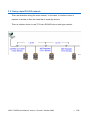
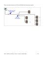
F.3. Star type RS-485 network
All RS-485 devices are wired directly to the main network, If the network is up to
1.2 Km, it will need a repeater (7510 series) to extend the network length.
uPAC-7186EX User Manual, Version 1.0 beta1, October 2008
--- 109
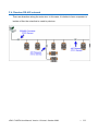
There is a better choice to use 7513 as a RS-485 hub on start type network.
uPAC-7186EX User Manual, Version 1.0 beta1, October 2008
--- 110
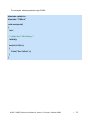
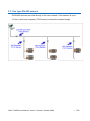
F.4. Random RS-485 network
There are branches along the main wire. In this case, it is better to have a repeater to
isolate or filter the noise that is made by devices.
uPAC-7186EX User Manual, Version 1.0 beta1, October 2008
--- 111
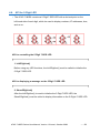
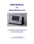
F.5. Pull-High/Pull-Low Resistors
The uPAC-7186EX provides two RS-485 serial port based on the master-slave
architecture, all of which have a pull-high/pull-low resistor, you can set it to master
mode or slave mode for implementing a RS-485 multi-drop network.
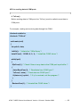
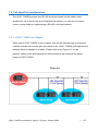
F.5.1. uPAC-7186EX as a Master
When one of uPAC-7186EX is set to master, then all the other devices on the same
network must be slave mode. then the master one‟s (uPAC-7186EX) pull-high/pull-low
resistors have to adjusted to enabled. Please refer to the Figure H-1 for the
jumpers‟ setting of the pull-high/pull-low resistors which are located at the power
board of uPAC-7186EX.
Figure H-1
uPAC-7186EX User Manual, Version 1.0 beta1, October 2008
--- 112
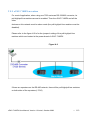
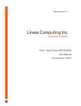
F.5.2. uPAC-7186EX as a slave
For most of application, when using one 7520 series as RS-232/485 converter, its
pull-high/pull-low resistors are set to enabled. Then the uPAC-7186EX and all the
other
devices on this network must be slave mode (the pull-high/pull-low resistors must be
disabled).
Please refer to the figure H-2 to for the jumpers‟ setting of the pull-high/pull-low
resistors which are located at the power board of uPAC-7186EX.
Figure H-2
If there are repeaters on the RS-485 network, there will be pull-high/pull-low resistors
on both sides of the repeaters (i-7510)
uPAC-7186EX User Manual, Version 1.0 beta1, October 2008
--- 113
uPAC-7186EX User Manual, Version 1.0 beta1, October 2008
--- 114