1
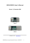
8411/8811 User Manual
(C language solution)
Version 1.0, January 2008
Service and usage information for
i-8411
i-8811
i-8411-G
i-8811-G
Written by Hans Chen
Edited by Anna Huang
8411/8811 User Manual, Version 1.0, January 2008, 8MS-002-10 --- 1
Warranty
All products manufactured by ICP DAS are under warranty regarding defective materials
for a period of one year, beginning from the date of delivery to the original purchaser.
Warning
ICP DAS assumes no liability for any damage resulting from the use of this product.
ICP DAS reserves the right to change this manual at any time without notice. The
information furnished by ICP DAS is believed to be accurate and reliable. However,
no responsibility is assumed by ICP DAS for its use, no for any infringements of patents
or other rights of third parties resulting from its use.
Copyright
Copyright © 2007 by ICP DAS Co., Ltd. All rights are reserved.
Trademarks
The names used in this manual are for identification purpose only and may be registered
trademarks of their respective companies.
8411/8811 User Manual, Version 1.0, January 2008, 8MS-002-10 --- 2
Table of Contents
1. Introduction ........................................................................................... 5
1.1. Features ............................................................................................................7
1.2. Specifications .................................................................................................10
1.3. Overview .........................................................................................................12
1.4. Companion CD...............................................................................................13
2. Quick Start........................................................................................... 14
2.1. Hardware Installation ....................................................................................14
2.1.1. Install your controller .................................................................................... 14
2.1.2. Insert the I/O module ................................................................................... 16
2.2. Software Installation......................................................................................21
2.3. Download programs to your controller.......................................................22
2.3.1. Establish a connection and disabling the running program.............. 22
2.3.2. Download and executing programs on your controller ...................... 25
2.4. Upgrade the MiniOS7 image file .................................................................27
3. Your First Program............................................................................. 29
3.1. Set up Your Compiler ....................................................................................29
3.2.1. Install the compiler ........................................................................................ 30
3.2.2. Set the environment variables .................................................................. 33
3.2. API for Your Controller ..................................................................................36
3.3. Create Your First Program ...........................................................................38
4. API and Demo Reference................................................................. 46
4.1. API for COM Port...........................................................................................48
4.1.1. API for standard I/O Port............................................................................. 53
4.1.2. More demo reference .................................................................................. 55
4.2. API for I/O Modules .......................................................................................57
4.2.1. Steps to use i-8K I/O modules in slots .................................................... 58
4.2.2. Steps to use i-87K I/O modules in slots ................................................. 59
4.2.3. Steps to use i-7K and i-87K I/O modules that connected to COM port... 61
8411/8811 User Manual, Version 1.0, January 2008, 8MS-002-10 --- 3
Table of Contents
4.3. API for EEPROM................................................................................. 63
4.4. API for Flash Memory ......................................................................... 65
4.5. API for NVRAM and RTC .................................................................... 67
4.6. API for 5-Digit LED.............................................................................. 69
4.7. API for Timer ....................................................................................... 71
4.8. API for WatchDog Timer (WDT) .......................................................... 73
A. Dimension ..................................................................................75
A.1. i-8411.................................................................................................. 75
A.2. i-8811.................................................................................................. 76
B. What is MiniOS7.........................................................................77
C. What is MiniOS7 Utility ..............................................................78
D. i-8K and i-87K Series I/O Modules.............................................79
E. More Compiler Settings..............................................................80
E.1. Turbo C 2.01 Compiler ....................................................................... 80
E.2. BC++ 3.1 IDE ..................................................................................... 83
E.3. MSC 6.00 Compiler ............................................................................ 87
E.4. MSVC 1.50 Compiler.......................................................................... 89
F. Application of RS-485 Network ...................................................93
F.1. Basic RS-485 Network ........................................................................ 93
F.2. Daisy Chain RS-485 Network ............................................................. 93
F.3. Star Type RS-485 Network.................................................................. 94
F.4. Random RS-485 Network ................................................................... 95
F.5. Pull-High/Pull-Low Resistor................................................................. 96
F.5.1. i-8411/i-8811 as a slave ................................................................ 96
F.5.2. i-8411/i-8811 as a Master.............................................................. 98
G. How to prevent illegal software copy..........................................99
8411/8811 User Manual, Version 1.0, January 2008, 8MS-002-10 --- 4
CHAPTER
1
Introduction
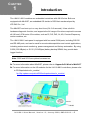
The i-8411/ i-8811 modules are embedded controllers with 4/8 I/O slots. Both are
equipped with MiniOS7, an embedded OS similar to DOS that was developed by
ICP DAS Co., Ltd.
The MiniOS7 can boot up in a very short time (0.4~0.8 seconds). It has a built-in
hardware diagnostic function, and supports the full range of functions required to access
all i-8K and i-87K series I/O modules, such as DI, DO, DIO, AI, AO, Counter/Frequency,
motion modules, etc.
The i-8411/i-8811 back panel is equipped with four serial COM ports, including RS-232
and RS-485 ports, and can be used for remote data acquisition and control applications,
including environment monitoring, power management and factory automation. By using
S-256 (256 KBytes) or S-512 (512 KBytes) battery backup SRAM, they provide data
logger function.
Note: S256 and S512 are optional accessories.
► For more information about MiniOS7, please refer to “Appendix B. What is MiniOS7”
► For more information on the I/O modules for the i-8411/i-8811 controllers, please refer
to CD:\Napdos\dcon\io_module\
ftp://ftp.icpdas.com/pub/cd/8000cd/napdos/dcon/io_module/
8411/8811 User Manual, Version 1.0, January 2008, 8MS-002-10 --- 5
Optional Accessories
S256
256 K SRAM module with battery backup
S512
512 K SRAM module with battery backup
KA-52F
DIN-KA52F
100 ~ 250 VAC input, 24 VDC/1 A output, flat-type power supply
KA-52F with DIN-Rail mount
DP-665
85 ~ 270 VAC input, 24 VDC/1.7 A and 5 VDC/0.5 A output power supply
DP-660
24 VDC/1.7 A 5 VDC/0.5 A power supply
DP-1200
24 VDC/5 A power supply
8411/8811 User Manual, Version 1.0, January 2008, 8MS-002-10 --- 6
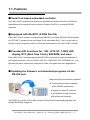
1.1. Features
Serial Port-based embedded controller
The i-8411/i-8811 modules are serial port embedded controllers that allows COM port
applications to access and control remote I/O data in RS-232 or industrial RS-485
networks.
Equipped with MiniOS7 (A DOS like OS)
Each i-8411/i-8811 module is equipped with MiniOS7, a friendly DOS like OS developed
by ICP DAS. C compilers that can create 16 bit executable files (*.exe) can be used to
develop custom programs, which can then be downloaded to the i-8411/i-8811 module.
Provides API Functions for: i-8K, i-87K I/O, 7-SEG LED
display, RTC (Real Time Clock), EEPROM, and more
Each i-8411/i-8811 module supports MiniOS7 API functions that includes hundreds of
pre-defined functions, such as i-8000, i-87K I/O, 7-SEG LED, RTC, EEPROM, etc., and
provides the demo code mostly required for users to program their own applications.
Updating the firmware, and download programs via the
RS-232 port
When should the firmware be updated?
¼ The firmware should be updated
when ICPDAS announces:
Support for new I/O modules
The addition of new functions
Bug fixes and revisions
The COM1 port of the i-8411/i-8811 module can be used to download programs and
update the MiniOS image file.
8411/8811 User Manual, Version 1.0, January 2008, 8MS-002-10 --- 7
Hardware designed to protect software
The i-8411/i-8811 module is equipped with a unique onboard 64-bit hardware serial
number. Custom application software can be used to check this number to prevent illegal
copying of software. An alternative method of achieving this goal is to use the ASICKey
approach. ASICKeys can be numbered from 00 ~ 99. Each individual number is only sold
to a single customer. Custom software can be used to check the specific ASICKey number
to determine whether the application will quit or continue to execute.
64-bit built-in hardware serial number
ASICKey (optional)
► For more information regarding the 64-bit hardware serial number and ASICKey,
please refer to “Appendix G. How to prevent illegal copying of software”.
Innovation design on reliability, flexibility and expansibility
Each i-8411/i-8811 module is equipped with 4/8 I/O slots and multiple serial ports.
It not only supports i-8K and i-87K series I/O modules, such as DI, DO, DIO, AI, AO
and Counter/Frequency for I/O slot applications, but also i-7K series I/O modules to
allow a wide range of RS-485 network applications.
Each I/O module allows a range of channel numbers. For example, when combined
with the i-8040 or i-8041, the i-8411/i-8811 provides a maximum of 256 digital input or
digital output channels.
► For more information on i-8K and i-87K series modules, please refer to
“Appendix C. i-8K and i-87K series I/O modules”.
Built-in WatchDog Timer
The built-in WatchDog Timer will reset the CPU module if a failure occurs in either the
hardware or software. If the application program does not refresh the WatchDog timer
within 0.8 sec, the WatchDog Timer will initiate a reset of the CPU.
8411/8811 User Manual, Version 1.0, January 2008, 8MS-002-10 --- 8
Input protection circuitry
The input protection circuitry on both the network and power supply protects the system
from external signals, such as mains spikes and ambient electrical noise. In addition, the
central processing module is isolated from external signals in three ways. This is achieved
through an I/O isolation of up to 3KV, power isolation of up to 3KV and network isolation of
up to 2KV.
High-performance integrated power supply
The built-in 20W isolated power supply is rated to perform linearly up to full loading.
Ventilated housing designed to work between -25℃ ~ +75℃
Each i-8411/i-8811 module is housed in a plastic-based box with a column-like ventilator
that can help to cool the work environment inside the box and allow the i-8411/i-8811
module to operate between -25℃ and +75℃.
8411/8811 User Manual, Version 1.0, January 2008, 8MS-002-10 --- 9
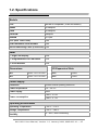
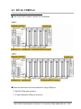
1.2. Specifications
Module
CPU
80188 or compatible (16-bit and 40MHz)
SRAM
512KBytes
Flash
512KBytes
EEPROM
2KBytes
NVRAM
31 byes
RTC (Real Time Clock)
Yes
64-bit Hardware Serial Number
Yes
Built-in Watchdog Timer (0.8 second) Yes
SMMI
5 - Digit LED Display
Yes
3 - Programmable LED Indicators
Yes
4 - Push Buttons
Yes
Dimensions
I/O Expansion Slots
8411
230 x 110 x 75.5 mm
8411
4 Slots
8811
354 x 110 x 75.5 mm
8811
8 Slots
Power Supply
Protection
Power reverse polarity protection
Power requirement
10 ~ 30 VDC
Power supply
20W
Power consumption
i-8411: 3.9 W
i-8811: 5.1 W
Operating Environment
Operating Temperature
–25°C ~ +75°C
Storage Temperature
–30°C ~ +85°C
Humidity
5 ~ 95%, Non-condensing
8411/8811 User Manual, Version 1.0, January 2008, 8MS-002-10 --- 10
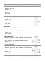
Communication Interface (Cont.)
COM0 (Internal RS-485 interface that can communication with i-87K I/O modules)
Baud Rate – 115200 bps
Data Bits – 8
Parity – None, Even, Odd
Stop Bits – 1
FIFO – 1 byte
Note: CPU internal uart
COM1 (RS-232 used to update firmware)
Baud Rate – 115200, 57600, 38400, 19200, 9600, 4800, 2400, 1200 bps
Data Bits – 7, 8
Parity – None, Even, Odd
Stop Bits – 1
FIFO – 1 byte
Note: CPU internal uart
COM2 (RS-485)
Baud Rate – 115200, 57600, 38400, 19200, 9600, 4800, 2400, 1200 bps
Data Bits – 5, 6, 7, 8
Parity – None, Even, Odd, Mark (Always 1), Space (Always 0)
Stop Bits – 1, 2
FIFO – 16 bytes
Note: 16C550 compatible
COM3 (RS-232/RS-485)
Baud Rate – 115200, 57600, 38400, 19200, 9600, 4800, 2400, 1200 bps
Data Bits – 5, 6, 7, 8
Parity – None, Even, Odd, Mark (Always 1), Space (Always 0)
Stop Bits – 1, 2
FIFO – 16 bytes
Note: 16C550 compatible
COM4 (RS-232)
Baud Rate – 115200, 57600, 38400, 19200, 9600, 4800, 2400, 1200 bps
Data Bits – 5, 6, 7, 8
Parity – None, Even, Odd, Mark (Always 1), Space (Always 0)
Stop Bits – 1, 2
FIFO – 16 bytes
Note: 16C550 compatible
8411/8811 User Manual, Version 1.0, January 2008, 8MS-002-10 --- 11
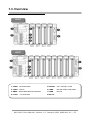
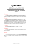
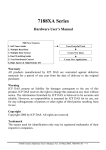
1.3. Overview
i-8411
i-8811
1. COM3
RS-232/RS485
5. Initialize
INIT* and INIT*COM
2. COM1
RS232
6. COM2
RS-485 (Data+ and Data-)
3. SMMI
Small Main Machine Interface
7. COM4
RS-232
4. Power +VS and GND
8. NET ID.
8411/8811 User Manual, Version 1.0, January 2008, 8MS-002-10 --- 12
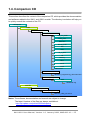
1.4. Companion CD
This section describes the content of the companion CD, which provides the documentation
and software related to the i-8411 and i-8811 module. The directory tree below will help you
to quickly search the contents of the CD.
CD:\Napdos
8000
841x881x
Demo
7k8k_for_COM
COM_ports
DataTime
DCON_FUN
File
Hello
IO_in_Slot
Lib
Memory
Misc
Smmi
Timer
Demo.html
Documents
MiniOS7_Programming_document.html
OS_image
40M
8k050902.img
MiniOS7
Utility
MiniOS7_Programming
MiniOS7_utility_V316.exe
Notes: The software, documentation and manual are subject to change.
The latest Versions of the files are always available at:
http://ftp.icpdas.com/pub/cd/8000cd/napdos
8411/8811 User Manual, Version 1.0, January 2008, 8MS-002-10 --- 13
CHAPTER
2
Quick Start
2.1. Hardware Installation
2.1.1. Installing the controller
Step 1: Mount the controller
The controller can be mounted in two different ways:
Screw panel or DIN-Rail mounting.
Screw Panel Mounting
DIN-Rail Mounting
8411/8811 User Manual, Version 1.0, January 2008, 8MS-002-10 --- 14
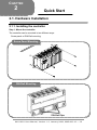
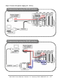
Step 2: Connect the power supply (10 ~ 30 VDC)
Communication using the RS-232 interface
Communication using the RS-485 interface
8411/8811 User Manual, Version 1.0, January 2008, 8MS-002-10 --- 15
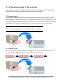
2.1.2. Operating modes of the controller
After apply power, the i-8411/i-8811 module includes the following modes for protecting
the system. This section describes when the following modes boot.
1. Running mode
The running mode represents there is the program running on the i-8411/i-8811 module,
and the 5-digits 7-SEG LED will show the message according to the running program, but if
during this time there is another program running on the i-8411/i-8811 module, the 5-digits
7-SEG LED isn’t managed with this program, it will stop motion at the present state.
Note: If you want to stop the running program, please refer the
point 3. Switching the running mode into the console mode.
2. Console mode
The Console mode represents there is no program running on the i-8411/i-8811 module,
and the 5-digits 7-SEG LED will count the number as shown below:
‧‧‧‧‧
8411/8811 User Manual, Version 1.0, January 2008, 8MS-002-10 --- 16
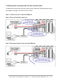
3. Switching the running mode into the console mode
To switch the running mode into the console mode, follows the following steps to stop
all programs running on the i-8411/i-8811 module.
Step 1: Connect the Init* to the Init*COM pins
Step 2: Power off and then power on
Step 3: Disconnect the Init* from the Init*COM pins
8411/8811 User Manual, Version 1.0, January 2008, 8MS-002-10 --- 17
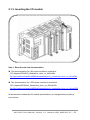
2.1.3. Inserting the I/O module
Step 1: Read the relevant documentation
► The documentation for i-8K series modules is located at:
CD:\Napdos\DCON\IO_Module\hw_dcon_on_8KUnit\8k
ftp://ftp.icpdas.com/pub/cd/8000cd/napdos/dcon/io_module/hw_dcon_on_8kunit/8k/
► The documentation for i-87K series modules is located at:
CD:\ Napdos\DCON\IO_Module\hw_dcon_on_8KUnit\87k
ftp://ftp.icpdas.com/pub/cd/8000cd/napdos/dcon/io_module/hw_dcon_on_8kunit/87k/
All documents includes the I/O module specifications, pin assignments and wiring
connections.
8411/8811 User Manual, Version 1.0, January 2008, 8MS-002-10 --- 18
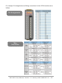
For example, Pin Assignments and Wiring connections for the i-87054 module are as
follows:
Pin Assignments
Wire
Connection
8411/8811 User Manual, Version 1.0, January 2008, 8MS-002-10 --- 19
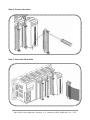
Step 2: Connect the wires
Step 3: Insert the I/O module
8411/8811 User Manual, Version 1.0, January 2008, 8MS-002-10 --- 20
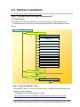
2.2. Software Installation
Step 1: Copy the 841x881x file folder to your Host PC
CD:\Napdos\8000\
The folder is an essential resource for users developing custom programs and
contains libraries, header files, demo programs and more information as shown
below:
841x881x
Demo
7k8k_for_COM
COM_ports
DataTime
DCON_FUN
File
Hello
IO_in_Slot
Lib
Memory
Misc
Smmi
Timer
Demo.html
Documents
MiniOS7_Programming_document.html
OS_image
40M
8k050902.img
Step 2: Install the MiniOS7 Utility
The MiniOS7 Utility is a tool that can be used to configure and upload files to the
controller and is located at:
CD:\Napdos\minios7\utility\minios7_utility\
ftp://ftp.icpdas.com/pub/cd/8000cd/napdos/minios7/utility/minios7_utility/
8411/8811 User Manual, Version 1.0, January 2008, 8MS-002-10 --- 21
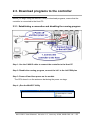
2.3. Download programs to the controller
Before you begin using the MiniOS7 Utility to download programs, ensure that the
controller is connected to the Host PC.
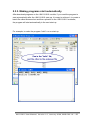
2.3.1. Establishing a connection and disabling the running program
Step 1: Use the CA0915 cable to connect the controller to the Host PC
Step 2: Disable the running program, connect the Init* to the Init*COM pins
Step 3: Power off and then power on the module
The CPU doesn’t run the autoexec.bat during the power on stage.
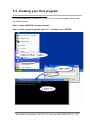
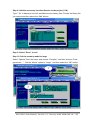
Step 4:Run the MiniOS7 Utility
8411/8811 User Manual, Version 1.0, January 2008, 8MS-002-10 --- 22
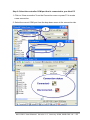
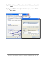
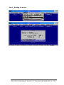
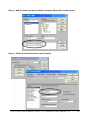
Step 6: Select the controller COM port that is connected to your Host PC
1. Click on “New connection” from the Connection menu or press F2 to create
a new connection.
2. Select the correct COM port from the drop down menu in the connection tab.
8411/8811 User Manual, Version 1.0, January 2008, 8MS-002-10 --- 23
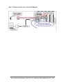
Step 7: Disconnect the Init* to the Init*COM pins
8411/8811 User Manual, Version 1.0, January 2008, 8MS-002-10 --- 24
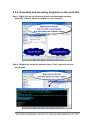
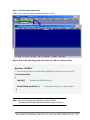
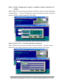
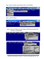
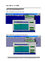
2.3.2. Download and executing programs on the controller
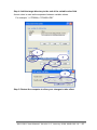
Step 1: Right click on the file that you wish to downloaded and then
select the “Upload” option to upload it on the controller.
Step 2:Right click on the file and then select “Run” option to execute
the program
8411/8811 User Manual, Version 1.0, January 2008, 8MS-002-10 --- 25
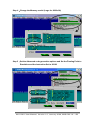
2.3.3. Making programs start automatically
After download programs on the i-8411/i-8811 module, if you need the program to
start automatically after the i-8411/i-8811 start-up, it is easy to achieve it, to create a
batch file called autoexec.bat and then upload it on the i-8411/i-8811 controller,
the program will start automatically in the next start-up.
For example, to make the program “hello” run on start-up.
8411/8811 User Manual, Version 1.0, January 2008, 8MS-002-10 --- 26
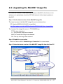
2.4. Upgrading the MiniOS7 image file
ICP DAS will continue to add additional features to MiniOS7 in the future, so we
advise you to periodically check the ICP DAS web site for the latest updates to
MiniOS7.
Step 1: Get the latest version of the MiniOS7 image file
The latest version of the MiniOS7 image file can be obtained from:
CD:\Napdos\8000\841x881x\OS_image\40m\
http://ftp.icpdas.com/pub/cd/8000cd/napdos/8000/841x881x/os_image/40m/
The format of the image file name is: TTYYMMDD.img
TT: The type of product.
YY: The year this image was released
MM: The month this image was released
DD: The day this image was released
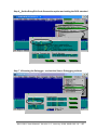
Step 2: Establish a connection
Refer to “Section 2.3.1. Establishing a Connection” for more details
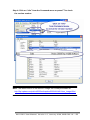
Step 3: Select the latest version of the MiniOS7 image file from the Host PC
8411/8811 User Manual, Version 1.0, January 2008, 8MS-002-10 --- 27
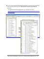
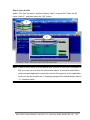
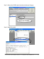
Step 4: Click on “Info” from the Command menu or press F7 to check
the version number
Note: The latest version of the MiniOS7 image file is always available at:
http://ftp.icpdas.com/pub/cd/8000cd/napdos/8000/841x881x/os_image/40m/
8411/8811 User Manual, Version 1.0, January 2008, 8MS-002-10 --- 28
CHAPTER
3
Your First Program
Before writing your first program, ensure that you have the necessary C/C++ compiler
and the corresponding functions library for the i-8411/i-8811 on your system.
3.1. Setting up the compiler
The following compilers are available for the controller:
Turbo C++ Version 1.01 (Freeware)
Turbo C Version 2.01 (Freeware)
Borland C++ Versions 3.1 - 5.2.x
MSC
MSVC ++
Note: ICP DAS suggests that the Borland C++ version compiler is used as the
libraries provided on the companion CD have been created using this compiler.
Special attention should be paid to the following items before using the
compiler to develop custom applications:
z Generate a standard DOS executable program
z Set the CPU option to 80188/80186
z Set the floating point option to EMULATION if floating point computation is
required. (Be sure not to choose 8087)
z Cancel the Debug Information function as this helps to reduce program size.
(MiniOS7 supports this feature.)
► For more information about compiler settings, please refer to
“Appendix E. More Compiler Settings”
8411/8811 User Manual, Version 1.0, January 2008, 8MS-002-10 --- 29
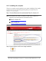
3.2.1. Installing the compiler
If there is no compiler currently installed on your system, installation of the compiler
should be the first step. The following section guides you to install Turbo C++
Version 1.01 on your system.
Step 1: Go to the Borland web site and download Turbo C++ Version 1.01
Note: Free versions of the Turbo C++ Version 1.01 and Turbo C Version 2.01
compilers can be downloaded from the Borland web site.
Turbo C++ Version 1.01
http://dn.codegear.com/article/21751
Turbo C Version 2.01
http://dn.codegear.com/article/20841
Step 2: Double click the exe file icon to begin installation
8411/8811 User Manual, Version 1.0, January 2008, 8MS-002-10 --- 30
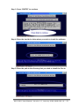
Step 3: Press “ENTER” to continue
Step 4: Enter the hard drive letter where you wish to install the software
Step 5: Enter the path to the directory that you wish to install the files to
8411/8811 User Manual, Version 1.0, January 2008, 8MS-002-10 --- 31
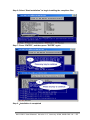
Step 6: Select “Start Installation” to begin installing the compilers files
Step 7: Press “ENTER”, and then press ”ENTER” again
Step 8:Installation is completed
8411/8811 User Manual, Version 1.0, January 2008, 8MS-002-10 --- 32
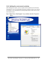
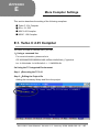
3.2.2. Setting the environment variables
After installing the compiler, several compilers will be available from the Windows
Command Line. You can set the path environment variable so that you can execute
this compiler on the command line by entering simple names, rather than by using
their full path names.
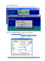
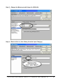
Step 1: Right Click on “My Computer” icon, and then select the “Properties”
option
8411/8811 User Manual, Version 1.0, January 2008, 8MS-002-10 --- 33
Step 2: Click the “Advanced” Tab, and then click the “Environment Variables”
Button
Step 3:Select “Path” under the System Variables option, and then click the
“Edit” Button
8411/8811 User Manual, Version 1.0, January 2008, 8MS-002-10 --- 34
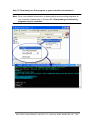
Step 4: Add the target directory to the end of the variable value field
A semi-colon is used as the separator between variable values.
For example, ”;c:\TC\BIN\;c:\TC\INCLUDE\”
Step 5: Restart the computer to allow your changes to take effect
8411/8811 User Manual, Version 1.0, January 2008, 8MS-002-10 --- 35
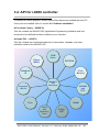
3.2. API for i-8000 controller
To develop a custom program, ensure that the files below are installed the Host PC.
If they are not installed, refer to “section 2.2. Software Installation”.
■ Functions Library ─ 8000E.lib
This file contains the MiniOS7 API (Application Programming Interface) and has
hundreds of pre-defined functions related to your controller.
■ Header File ─ 8000E.h
This file contains the forward declarations of subroutines, variables, and other
identifiers used for the MiniOS7 API.
COM
Ports
Others
(MISC)
EEPROM
Flash
Memory
Standard
IO
MiniOS7
API
Functions
Programm
-able IO
NVRAM
and
RTC
SRAM
Files
Timer
and
WatchDog
Timer
5-Digit
LED
8411/8811 User Manual, Version 1.0, January 2008, 8MS-002-10 --- 36
► For full usage information regarding the description, prototype and the arguments
of the functions, please refer to the “MiniOS7 API Functions User Manual”
located at:
CD:\Napdos\minios7\document\minios7_api_functions_ver1.0.pdf
http://ftp.icpdas.com/pub/cd/8000cd/napdos/minios7/document/minios7_api_fun
ctions_ver1.0.pdf
8411/8811 User Manual, Version 1.0, January 2008, 8MS-002-10 --- 37
3.3. Creating your first program
If you don’t know how to use the TC++ (Turbo C++) to write a program, please take
the following steps.
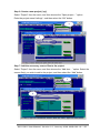
Step 1: Open a MS-DOS command prompt
Step 2: At the command prompt, type “TC”, and then press “ENTER”
8411/8811 User Manual, Version 1.0, January 2008, 8MS-002-10 --- 38
Step 3: Create a new source file
Select “File” from the menu, and then choose “New”
Step 4: Enter the following code. Note that the code is case-sensitive.
#include “8000E.h”
/* Include the header file that allows 8000e.lib functions to be used */
void main(void)
{
InitLib();
/* Initiate the 8000e library */
Print(“Hello world!\r\n”);
/* Print the message on the screen */
}
Note: The source file for this example can be found at:
CD:\Napdos\8000\841x881x\demo\Hello\Hello_C\Hello.c
8411/8811 User Manual, Version 1.0, January 2008, 8MS-002-10 --- 39
Step 5: Save the file
Select “File” from the menu, and then choose “Save” (or press F2). Enter the file
name “Hello.C”, and then select the “OK” button.
Note: If there is a text editor you are familiar with or prefer to use such as Notepad or
Edit, you may use it to write the code shown above. It should be noted that a
word processor application cannot be used for this purpose, as the application
must save the file as plain text. C language program files should always have a
“.C” extension name.
8411/8811 User Manual, Version 1.0, January 2008, 8MS-002-10 --- 40
Step 6: Create a new project (*prj)
Select “Project” from the menu, and then choose the “Open project…” option.
Enter the project name Hello.prj“, and then select the “OK” button.
Step 7: Add the necessary source files to the project
Select “Project” from the menu, and then choose the “Add item…” option. Select the
source file(s) you wish to add to the project, and then select the “Add” button.
8411/8811 User Manual, Version 1.0, January 2008, 8MS-002-10 --- 41
Step 8: Add the necessary function libraries to the project (*.lib)
Type “*.lib” to display a list of all available function library files. Choose the library file
you require and then select the “Add” button.
Step 9: Select “Done” to exit
Step 10: Set the memory model to large
Select “Options” from the menu, and choose “Compiler”, and then choose “Code
generation …”. Set the “Model” option to “Large”, and then select the “OK” button.
8411/8811 User Manual, Version 1.0, January 2008, 8MS-002-10 --- 42
Step 11: Set the “floating point” option to “emulation” and the “instruction” to
“80186”
Select “Options” from the menu, and choose “Compiler”, and then choose “Advanced
code generation…”. Set the “Floating Point” option to “Emulation” and the “Instruction”
option to “80186”, and then select the “OK” button.
Step 12: Set the TC++ 1.01 include and library directories
Select “Options” from the menu, and then choose “Directories…”. Set the “Include
Directories” and “Library Directories” option, and then click the “OK” button.
8411/8811 User Manual, Version 1.0, January 2008, 8MS-002-10 --- 43
Step 13: Build the project
Select “Compile” from the menu, and then choose the “Build all” option.
Step 14: Use the MiniOS7 Utility to connect to your controller
8411/8811 User Manual, Version 1.0, January 2008, 8MS-002-10 --- 44
Step 15: Download your first program to your controller and execute it
Note: For a more detailed introduction to downloading and executing programs on
your controller, please refer to “Section 2.3. Downloading and executing
programs to your controller”.
8411/8811 User Manual, Version 1.0, January 2008, 8MS-002-10 --- 45
CHAPTER
4
API and Demo Reference
There are several demo programs that have been designed for your controller. You
can examine the demo source code, which includes numerous comments, to
familiarize yourself with the MiniOS7 API, This will allow to quickly develop your own
applications quickly by modifying these demo programs.
Folder
File
Hello
Demo
Config_1_Basic
Reads information from a text file (basic).
Config_2_Advanced
Reads a config file (text file)(advanced).
Hello_C
Hello_C++
Misc
Smmi
Memory
DateTime
Timer
Explanation
Reads the library version and flash memory size.
Reset
Resets the software.
Runprog
Illustrates how to select an item and run it.
Serial
Illustrates how to retrieve 64-bit hardware unique serial number.
Watchdog
Enables the WDT or bypasses the enable WatchDog function.
SystemKey
Shows how to operate the systemkey function simply and easily.
Led
Shows how to control the red LED and 7-segment display.
S256
Shows how to read or write to the 256K byte battery backup.
DateTime
Shows how to read and write the date and time from the RTC.
For details of the demo programs available, please refer to the followingmo/
(1) Shows how to write a function to input data.
C_Style_IO
(2) Shows how to receive a string.
(3) Shows how to use a C function: sscanf or just use Scanf()
Receives data from COM port.
Com port
Receive
Slv_COM.c is in non-blocked mode
Receive.c is in blocked mode.
Slv_COM
ToCom_In_Out
A slave COM Port demo for (request/reply) or
(command/response) applications.
Illustrates how to Read/Write byte data via COM Port.
… more demo programs location:
ftp://ftp.icpdas.com.tw/pub/cd/8000cd/napdos/8000/common/minios7/de
8411/8811 User Manual, Version 1.0, January 2008, 8MS-002-10 --- 46
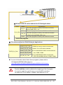
i-8K and i-87K I/O series modules for I/O Slot Applications
Folder
Demo
8K_DI
8073
IO_in_Slot
87K_DI
87024
Explanation
This demo program is used by 8K series DI modules,
such as 8040, 8051., etc.
This demo program is used for 8073 General Functions.
This demo program is used by 87K series Dl modules
in Com0, such as 87040, 87051, etc.
This demo program is used by the 87024 AO module.
… more demo programs
i-7K series modules for RS-485 Network Applications
Folder
7K 87K_for_Com
Demo
Explanation
7K87K_DI_for_Com
"COM Port" can be used to connect and
7K87K_DO_for_Com
control i-7k or i-87k series modules.
7K87K_AI_for_Com
For 8410/8810/8411/8811 module and can
AO_22_26_for_Com
AO_024_for_Com
use, COM2, COM3.
For 8430/8830/8431/8831 module and
(CPU 40 and 80M) can use, COM3, COM4.
► For more Information about these demo programs, please refer to:
CD:\Napdos\8000\841x881x\demo or
http://ftp.icpdas.com/pub/cd/8000cd/napdos/8000/841x881x/demo
Function InitLib(); must be called at the beginning of the C program.
It is used to make the .exe file can run on all i-8000 controllers
no matter its CPU is 40MHz or 80MHz, with Ethernet or not.
8411/8811 User Manual, Version 1.0, January 2008, 8MS-002-10 --- 47
4.1. API for COM Port
The i-8411/i-8811 module includes five COM ports:
i-8411:
i-8811:
There are two kinds of functions below for using COM port.
MiniOS7 COM port functions
(C style) Standard COM port functions
8411/8811 User Manual, Version 1.0, January 2008, 8MS-002-10 --- 48
You have the alternative of MiniOS7 COM ports functions or
(C style) Standard COM port functions. If you choose the ones, then the
another can not be used.
Summarize the results of the comparison between MiniOS7 COM port functions
and (C style) Standard COM port functions:
Buffer
Kinds of
Functions
MiniOS7
COM port
COM Port
0, 1, 2, etc.
(C style)
Standard
COM port
1 (Note)
RX
TX
1 KB
1 KB
512
256
Bytes
Bytes
Functions
Check
Send
Read
Show
data
data
data
data
IsCom()
ToCom()
ReadCom()
printCom()
Getch()
Print()
Kbhit()
Puts()
Putch()
Note: The standard COM port is the port that used to download program from PC
to the i-8000 controller.
8411/8811 User Manual, Version 1.0, January 2008, 8MS-002-10 --- 49
4.1.1. API for MiniOS7 COM ports
API for using COM ports
1. InstallCom()
Before any COM Port can be used, the driver must be installed by calling
InstallCom().
2. AddCom2fun()
Before using COM2, the AddCom2fun() must be called to work for i-8411/i-8811
modules.
3. RestoreCom()
If the program calls InstallCom(), the RestoreCom()must be called to restore the
COM Port driver.
API for checking if there is any data in the COM port input buffer
4. IsCom()
Before reading data from COM port, the IsCom() must be called to check whether
there is any data currently in the COM port input buffer.
API for reading data from COM ports
5. ReadCom()
After IsCom() confirms that the input buffer contains data, the ReadCom() must be
called to read the data from the COM port input buffer.
API for sending data to COM ports
6. ToCom()
Before sending data to COM ports, the ToCom() must be called to send data to
COM ports.
8411/8811 User Manual, Version 1.0, January 2008, 8MS-002-10 --- 50
For example, reading and receiving data through the COM1:
#include <stdio.h>
#include “8000E.h”
void main(void)
{
int quit=0, data;
InitLib(); /* Initiate the 8000e library */
InstallCom(1, 115200, 8, 0, 1); /* Install the COM1 driver */
while(!quit)
{
if(IsCom(1)) /* Check if there is any data in the COM port input buffer */
{
data=ReadCom(1); /* Read data from COM1 port */
ToCom(1, data); /* Send data via COM1 port */
if(data==’q’) quit=1; /* If ‘q’ is received, exit the program */
}
}
RestoreCom(1); /* Uninstall the COM1 driver */
}
8411/8811 User Manual, Version 1.0, January 2008, 8MS-002-10 --- 51
API for showing data from COM ports
7. printCom()
Functions such as printfCom() in the C library allow data to be output from
COM ports.
For example, showing data from the COM1 port:
#include <stdio.h>
#include “8000E.h”
void main(void)
{
int i;
/* Initiate the 8000e library */
InitLib();
InstallCom(1, 115200, 8, 0, 1); /* Install the COM1 driver */
for (i=0;i<10;i++)
{
printCom(1,”Test %d\n\r”, i);
}
Delay(10); /* Wait for all data are transmitted to COM port */
RestoreCom(1);
}
► For more demo program about the COM port, please refer to
CD:\Napdos\8000\841x881x\demo\com_ports\
ftp://ftp.icpdas.com/pub/cd/8000cd/napdos/8000/841x881x/demo/com_ports/
8411/8811 User Manual, Version 1.0, January 2008, 8MS-002-10 --- 52
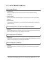
4.1.2. API for standard COM port
The standard COM port is the port that used to download program from PC to the
i-8000 controller.
Note: The following configurations of the standard COM port are fixed.
Baudrate=115200 bps, Data format=8 bits,
Parity check=none, Start bit=1, Stop bit=1
API for checking if there is any data in the input buffer
1. Kbhit()
Before reading data from standard I/O port, the kbhit() must be called to check
whether there is any data currently in the input buffer.
API for reading data from standard I/O port
2. Getch()
After kbhit() confirms that the input buffer contains data, the Getch() must be called
to read data from the input buffer.
API for sending data to standard I/O port
3. Puts() – For sending a string
Before sending data to standard I/O port, the Puts() must be called to send data to
COM Port.
4. Putch( ) – For sending one character
Before sending data to standard I/O port, the Putch() must be called to send data to
COM Port.
API for showing data from standard I/O port
5. Print()
Functions such as Print() in the C library allow data to be output from the COM Port.
8411/8811 User Manual, Version 1.0, January 2008, 8MS-002-10 --- 53
The following demo programs according to the same subject as demo programs of
previous section, you can comparing different methods for using COM port.
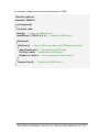
For example, reading and receiving data through COM1:
#include<stdio.h>
#include“8000E.h”
void main(void)
{
int quit=0, data;
InitLib();
/* Initiate the 8000e library */
while(!quit)
{
if(Kbhit()) /* Check if any data is in the input buffer */
{
data=Getch(); /* Read data from COM1 */
Putch(data); /* Send data to COM1 */
if(data==’q’) quit=1; /* If ‘q’ is received, exit the program */
}
}
}
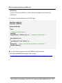
For example, showing data through COM1:
#include <stdio.h>
#include “8000E.h”
void main(void)
{
int i;
/* Initiate the 8000e library */
InitLib();
for(i=0;i<10;i++)
{
Print(“Test %d\n\r”,i);
}
}
8411/8811 User Manual, Version 1.0, January 2008, 8MS-002-10 --- 54
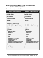
4.1.3. Comparison of MiniOS7 COM port function and
standard COM port function
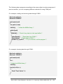
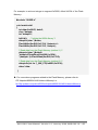
For example, learning to show the ASCII code:
MiniOS7 COM port functions
Standard COM port functions
#include<stdio.h>
#include"8000E.h"
#include<stdio.h>
#include"8000E.h"
void main(void)
{
unsigned char item;
void main(void)
{
unsigned char item;
InitLib();
InitLib();
InstallCom(1, 115200, 8, 0, 1);
printCom(1,”Hits any key.\n”);
printCom(1,”Hit the ESC to exit!\n”);
for(;;)
{
if(IsCom(1))
{
item=ReadCom(1);
if(item==’q’)
{
return;
}
else
{
printCom(1,”----------\n\r”);
printCom(1,”char:”);
ToCom(1,item);
printCom(1,"\n\rASCII(%c)\n\r”,item);
printCom(1,“Hex(%02X)\n\r”,item);
}
}
}
Delay(10);
RestoreCom(1);
}
Print("Hits any key.\n");
Print("Hits the ESC to exit !\n");
for(;;)
{
if(kbhit())
{
item=Getch();
if(item==’q’)
{
return;
}
else
{
Print(”----------\n\r”);
Print(“char:“);
Putch(item);
Print("\n\rASCII(%c)\n\r”,item);
Print(“Hex(%02X)\n\r”,item);
}
}
}
}
8411/8811 User Manual, Version 1.0, January 2008, 8MS-002-10 --- 55
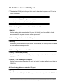
4.1.4. Request/Response protocol design on COM port
Request/Response communication is very typical protocol architecture, if you want
to design a command set of communication protocol as table below, you can refer to
“slave_com” demo:
Request
Response
GetCounter
>1234
SetDO1
>OK
ResetDO2
>OK
GetVersion
>V1.0.0
► For more demo program about the COM port, please refer to
CD:\Napdos\8000\841x881x\demo\com_ports\
ftp://ftp.icpdas.com/pub/cd/8000cd/napdos/8000/841x881x/demo/com_ports/
8411/8811 User Manual, Version 1.0, January 2008, 8MS-002-10 --- 56
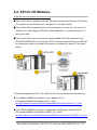
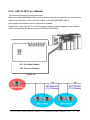
4.2. API for I/O Modules
The i-8411/i-8811 is equipped with 4/8 I/O slots to access the i-8K and i-87K series
I/O modules, as shown the point 1 and point 2 in the figure below.
The i-8411/i-8811 is equipped with multi-serial ports to access the i-7K series I/O
modules for a wide range of RS-485 network application, as shown the point 3 in
the figure below.
The i-8411/i-8811 can connect to the original i-8000 series I/O expansion units,
87K4/87K5/87K8/87K9, to access the i-87K I/O series modules through an RS-485
to extend the number of available I/O modules, as shown the point 4 in the figure
below.
The demo programs used for i-7K, i-8K and i-87K can be divided into the following:
► For i-8K and i-87K I/O modules in slots, please refer to:
CD:\Napdos\8000\841x881x\demo\IO_in_Slot\
ftp://ftp.icpdas.com/pub/cd/8000cd/napdos/8000/841x881x/demo/IO_in_Slot/
► For i-7K and i-87K I/O modules is connected to COM ports, please refer to:
CD:\Napdos\8000\841x881x\demo\7K87K_for_COM\
ftp://ftp.icpdas.com/pub/cd/8000cd/napdos/8000/841x881x/demo/7K87K_for_com/
8411/8811 User Manual, Version 1.0, January 2008, 8MS-002-10 --- 57
4.2.1. Steps to use i-8K I/O modules in slots
API for reading DI module
DI_8(), DI_16(), DI_32()
The DI_8(), DI_16() or DI_32() must
be called to read the input value of
DI modules.
For example, reading the input value of
slot 3 DI modules:
#include <stdio.h>
#include “8000E.h”
void main(void)
{
Int DI_data, iSlot=3;
InitLib(); /* Initiate the 8000e library */
for(;;)
{
/* Read the input value of Slot 3 DI module
*/
DI_data=DI_8(iSlot);
Print("DI Status== %x \n\r",DI_data);
}
}
8411/8811 User Manual, Version 1.0, January 2008, 8MS-002-10 --- 58
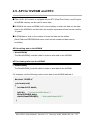
4.2.2. Steps to use i-87K I/O modules in slots
You must have to perform the following steps:
Step 1. Using Installcom() to Install the COM port driver.
Step 2. Using ChangeToSlot() to change to the slot which the i-87K module
plugged in.
Step 3. Using SendCmdTo7000(0,… ) to send command to the
i-87K module.
Step 4. Using ReceiveResponseFrom7000_ms() to get the response
from the i-87K module.
Step 5. Using RestoreCom() to restore the COM port driver.
1. The following configurations of the COM0 are fixed.
Baudrate=115200 bps
Data bit=8 bits
Parity check=none
Stop bit=1
2. The following configurations of the i-87K module that plugged in the slots
are fixed.
Address=0
Check Sum=Disable
Besides, the ChangeToSlot() function must be called.
8411/8811 User Manual, Version 1.0, January 2008, 8MS-002-10 --- 59
For example, sending a command ‘$00M’ to slot 7’s i-87K for getting the module
name:
#include <stdio.h>
#include “8000E.h”
void main(void)
{
unsigned char InBuf0[60];
InitLib(); /* Initiate the 8000e library */
InstallCom(0, 115200, 8, 0, 1); /* Install the COM0 driver */
InstallCom(1, 115200, 8, 0, 1); /* Install the COM1 driver */
ChangeToSlot(7);
SendCmdTo7000(0,"$00M",0);
/* Send a command to COM0 */
/* Timeout = 50ms, checksum disabled */
ReceiveResponseFrom7000_ms(0,InBuf0,50,0);
printCom(1,"Module Name=%s",InBuf0);
Delay(10); /* Wait for all data are transmitted to COM port */
RestoreCom(0); /* Uninstall the COM0 driver */
RestoreCom(1); /* Uninstall the COM1 driver */
}
8411/8811 User Manual, Version 1.0, January 2008, 8MS-002-10 --- 60
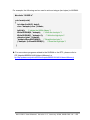
4.2.3. Steps to use i-7K and i-87K I/O modules that connected to COM port
You must have to perform the following steps:
Step 1. Calling Installcom to install the COM port driver.
Step 2. Calling AddCom2fun() when using COM2.
Step 3. Calling SendCmdTo7000() to send command to i-7K or i-87K
module.
Step 4. Calling ReceiveResponseFrom7000_ms() to get the response
from i-7K or i-87K module.
Step 5. Calling RestoreCom() to restore the COM port driver.
The AddCom2fun() must be called after calling InstallCom(2,…)
when using COM2.
8411/8811 User Manual, Version 1.0, January 2008, 8MS-002-10 --- 61
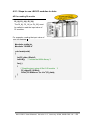
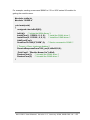
For example, sending a command ‘$00M’ to i-7K or i-87K series I/O module for
getting the module name:
#include <stdio.h>
#include “8000E.h”
void main(void)
{
unsigned char InBuf0[60];
InitLib(); /* Initiate the 8000e library */
InstallCom(1, 115200L, 8, 0, 0); /* Install the COM1 driver */
InstallCom(2, 115200L, 8, 0, 0); /* Install the COM2 driver */
AddCom2Fun();
SendCmdTo7000(2,"$00M",0); /* Send a command to COM2 */
/* Timeout = 50ms, checksum disabled */
ReceiveResponseFrom7000_ms(2,InBuf0,50,0);
PrintCom(1, "Module Name=%s",InBuf);
RestoreCom(1); /* Uninstall the COM1 driver */
RestoreCom(2); /* Uninstall the COM2 driver */
}
8411/8811 User Manual, Version 1.0, January 2008, 8MS-002-10 --- 62
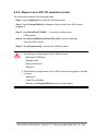
4.3. API for EEPROM
The EEPROM contains 8 blocks, and each block has 256 bytes, with a total size of 2,048
(2K) bytes capacity.
The default mode for EEPROM is write-protected mode.
Block 0
256
bytes
Block 1
Block 2
256
bytes
256
bytes
Block 3
256
bytes
Block 4
256
bytes
Block 5
256
bytes
Block 6
256
bytes
Block 7
256
bytes
Total Size is 2,048 (2K) bytes
API for writing data to the EEPROM
1. EE_WriteEnable()
Before writing data to the EEPROM, the EE_WriteEnable() must be called to
write-enable the EEPROM.
2. EE_WriteProtect()
After the data has finished being written to the EEPROM, the EE_WriteProtect()
must be called to in order to write-protect the EEPROM.
3. EE_MultiWrite()
After using the EE_WriteEnable() to write-enable EEPROM, the EE_MultiWrite()
must be called to write the data.
API for reading data from the EEPROM
4. EE_MultiRead()
The EE_WriteEnable() must be called to read data from the EEPROM no matter
what the current mode is.
8411/8811 User Manual, Version 1.0, January 2008, 8MS-002-10 --- 63
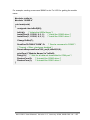
For example, to write data to block1, address 10 of the EEPROM:
#include “8000E.h”
void main(void)
{
int data=0x55, data2;
InitLib(); /* Initiate the 8000e library */
EE_WriteEnable();
EE_MultiWrite(1,10,1,&data);
EE_WriteProtect();
EE_MultiRead(1,10,1,&data2);
/* Now data2=data=0x55 */
}
Note: To write an integer to the EEPROM, the EE_WriteEnable() function must be
called twice, in the same manner as writing data to the NVRAM.
► For more demo programs related to the EEPROM, please refer to:
CD:\Napdos\8000\841x881x\demo\Memory\ or
ftp://ftp.icpdas.com/pub/cd/8000cd/napdos/8000/841x881x/demo/Memory/
8411/8811 User Manual, Version 1.0, January 2008, 8MS-002-10 --- 64
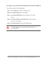
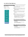
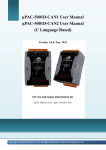
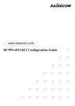
4.4. API for Flash Memory
The i-8411/i-8811 module contains 512K
Free – 448 K bytes
bytes of Flash memory.
MiniOS7 – 64 K bytes
MiniOS7 uses the last 64K bytes, the other
Total Size – 512 K bytes
parts of the memory are used to store user
Free
--- 0 x 8000
programs or data.
Each bit of the Flash memory only can be
Free
--- 0 x 9000
written from 1 to 0 and cannot be written
from 0 to 1.
Free
Free
Free
Free
--- 0 x A000
--- 0 x B000
Before any data can be written to the Flash
memory, the flash must be erased first,
which returns all data to 0xFF, meaning that
--- 0 x C000
all data bits are set to “1”. Once their is
completed, new data can be written.
--- 0 x D000
API for writing data to the Flash Memory
Free
--- 0 x E000
MiniOS7
--- 0 x F000
1. FlashWrite()
The FlashWrite() must be called to write
data to the Flash Memory.
API for reading data from the Flash Memory
2. FlashRead()
The FlashRead() must be called to read data
from the Flash Memory.
8411/8811 User Manual, Version 1.0, January 2008, 8MS-002-10 --- 65
For example, to write an integer to segment 0xD000, offset 0x1234 of the Flash
Memory:
#include “8000E.h”
void main(void)
{
int data=0xAA55, data2;
char *dataptr;
int *dataptr2;
InitLib(); /* Initiate the 8000e library */
dataptr=(char *)&data;
FlashWrite(0xd000,0x1234, *dataptr++);
FlashWrite(0xd000,0x1235, *dataptr);
/* Read data from the Flash Memory (method 1) */
dataprt=(char *)&data2;
*dataptr=FlashRead(0xd000,0x1234);
*(dataptr+1)=FlashRead(0xd000,0x1235);
/* Read data from the Flash Memory (method 2) */
dataptr2=(int far *)_MK_FP(0xd000,0x1234);
data=*data;
}
► For more demo programs related to the Flash Memory, please refer to:
CD:\Napdos\8000\841x881x\demo\Memory\ or
ftp://ftp.icpdas.com/pub/cd/8000cd/napdos/8000/841x881x/demo/Memory/
8411/8811 User Manual, Version 1.0, January 2008, 8MS-002-10 --- 66
4.5. API for NVRAM and RTC
The i-8411/i-811 module is equipped with an RTC (Real Time Clock), and 31 bytes
of NVRAM memory can be used to store data.
NVRAM is the same as SRAM, but it uses a battery to retain the data, so the data
store in the NVRAM is not lost when the module is powered off and can be used for
10 years.
NVRAM has no limit on the number of times the data can be written.
(Both Flash and EEPROM both have a limit on the numbers of data can be
re-written.)
API for writing data to the NVRAM
1. WriteNVRAM()
The WriteNVRAM() must be called in order to write data to the NVRAM.
API for reading data from the NVRAM
2. ReadNVRAM()
The ReadNVRAM() must be called in order to write data to the NVRAM.
For example, use the following code to write data to the NVRAM address 0:
#include “8000E.h”
void main(void)
{
int data=0x55, data2;
InitLib(); /* Initiate the 8000e library */
WriteNVRAM(0,data);
data2=ReadNVRAM(0); /* Now data2=data=0x55 */
}
8411/8811 User Manual, Version 1.0, January 2008, 8MS-002-10 --- 67
For example, the following can be used to write an integer (two bytes) to NVRAM:
#include “8000E.h”
void main(void)
{
int data=0xAA55, data2;
char *dataptr=(char *)&data;
InitLib(); /* Initiate the 8000e library */
WriteNVRAM(0, *dataptr); /* Write the low byte */
WriteNVRAM(1, *dataptr+1); /* Write the high byte */
dataptr=(char *) &data2;
*dataptr=ReadNVRAM(0); /* Read the low byte */
(*dataptr+1)=ReadNVRAM(1); /* Read the high byte */
}
► For more demo programs related to the NVRAM or the RTC, please refer to:
CD:\Napdos\8000\841x881x\demo\Memory\ or
ftp://ftp.icpdas.com/pub/cd/8000cd/napdos/8000/841x881x/demo/Memory/
8411/8811 User Manual, Version 1.0, January 2008, 8MS-002-10 --- 68
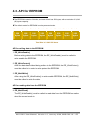
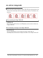
4.6. API for 5-Digit LED
The i-8411/i-8811 module contains a 5-Digit 7-SEG LED with a decimal point on the
left-hand side of each digit, which be used to display numbers, IP addresses, time,
and so on.
API for controlling the 5-Digit 7-SEG LED
1. Init5DigitLed()
Before using any LED functions, the Init5DigitLed() must be called to initialize the
5-Digit 7-SEG LED.
API for displaying a message on the 5-Digit 7-SEG LED
2. Show5DigitLed()
After the Init5DigitLed() is used to initialize the 5-Digit 7-SEG LED, the
Show5DigitLed() must be called to display information on the 5-Digits 7-SEG LED.
8411/8811 User Manual, Version 1.0, January 2008, 8MS-002-10 --- 69
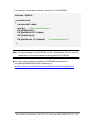
For example, use the following code to display “8000E” on the 5-Digit 7-SEG LED:
#include “8000E.h”
void main(void)
{
InitLib(); /* Initiate the 8000e library */
Init5DigitLed();
Show5DigitLed(1,8);
Show5DigitLed(2,0);
Show5DigitLed(3,0);
Show5DigitLed(4,0);
Show5DigitLed(5,14);
/* The ASCII code for the letter ‘E’ is 14 */
}
► For more demo programs related to use the 5-Digit 7-SEG LED, please refer to:
CD:\Napdos\8000\841x881x\demo\Smmi\ or
ftp://ftp.icpdas.com/pub/cd/8000cd/napdos/8000/841x881x/demo/Smmi/
8411/8811 User Manual, Version 1.0, January 2008, 8MS-002-10 --- 70
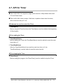
4.7. API for Timer
The i-8411/i-8811 can support a single main time tick, 8 Stop Watch timers and
8 Count Down timers.
The i-8411/i-8811 uses a single 16-bit timer to perform these timer functions,
with a timer accuracy of 1 ms.
API that can be used to control the Timer
1. TimerOpen()
Before using the Timer functions, the TimerOpen() must be called at the beginning
of the program.
API for reading the Timer
2. TimerResetValue()
Before reading the Timer, the TimerResetValue() must be called to reset the main
time ticks to 0.
3. TimerReadValue()
After the TimerResetValue() has reset the main time ticks to 0, the
TimerReadValue() must be called to read the main time tick.
API for stopping the Timer
4. TimerClose()
Before ending the program, the TimerClose() must be called to stop the Timer.
8411/8811 User Manual, Version 1.0, January 2008, 8MS-002-10 --- 71
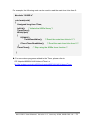
For example, the following code can be used to read the main time ticks from 0:
#include “8000E.h”
void main(void)
{
Unsigned long time iTime;
InitLib(); /* Initiate the 8000e library */
TimerOpen();
While(!quit)
{
If(Kbhit())
TimerResetValue(); /* Reset the main time ticks to 0 */
iTime=TimerReadValue();
}
TimerClose();
/* Read the main time ticks from 0 */
/* Stop using the 8000e timer function */
}
► For more demo programs related to the Timer, please refer to:
CD:\Napdos\8000\841x881x\demo\Timer\ or
ftp://ftp.icpdas.com/pub/cd/8000cd/napdos/8000/841x881x/demo/Timer
8411/8811 User Manual, Version 1.0, January 2008, 8MS-002-10 --- 72
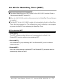
4.8. API for WatchDog Timer (WDT)
The default WatchDog timer (WDT) value for the i-8411/i-8811 module is fixed at
0.8 seconds for MiniOS7 version 2.0.
When the i-8411/i-8811 module is first powered on, the WatchDog Timer will always
be enabled.
The MiniOS7 for the i-8411/i-8811 module will automatically refresh the WatchDog
Timer after being powered on. The software driver can be called by a user program
to prevent the MinOS7 from refreshing the WatchDog Timer.
API for refreshing WDT
1. EnableWDT()
The WDT is always enabled, before user’s programming to refresh it, the
EnableWDT() must be called to stop refreshing WDT.
2. RefreshWDT()
After EnableWDT() stop refreshing WDT, the RefreshWDT() must be called to
refresh the WDT.
3. DisableWDT()
After user’s programming to refresh WDT, the DisableWDT() should be called to
automatically refresh the WDT.
8411/8811 User Manual, Version 1.0, January 2008, 8MS-002-10 --- 73
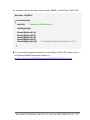
For example, to refresh the Watchdog Timer:
#include “8000E.h”
void main(void)
{
Unsigned long time iTime;
InitLib(); /* Initiate the 8000e library */
Enable WDT();
While(!quit)
{
RefreshWDT();
User_function();
}
DisableWDT();
}
► For more demo program about the WatchDog Timer, please refer to
CD:\Napdos\8000\841x881x\demo\Misc\
ftp://ftp.icpdas.com/pub/cd/8000cd/napdos/8000/841x881x/demo/Misc/
8411/8811 User Manual, Version 1.0, January 2008, 8MS-002-10 --- 74
APPENDIX
A
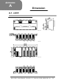
Dimension
A.1. i-8411
Back View
Side View
Top View
+VS
In put:
10 ~3 0VDC
GN D
INIT*
Initialize
IN IT *COM
DATA+
RS -485
DAT A-
Front View
8411/8811 User Manual, Version 1.0, January 2008, 8MS-002-10 --- 75
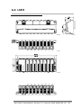
A.2. i-8811
Back View
Top View
+VS
Input:
10~30VDC
GND
INIT*
Initialize
INIT*COM
DATA+
RS-485
DATA-
Front View
8411/8811 User Manual, Version 1.0, January 2008, 8MS-002-10 --- 76
Side View
APPENDIX
B
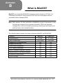
What is MiniOS7
MiniOS7 is an embedded ROM-DOS operating system design by ICP DAS. It is
functionally equivalent to other brands of DOS, and can run programs that are
executable under a standard DOS.
Note: DOS (whether PC-DOS, MS-DOS or ROMDOS) is a set of commands or code
that tells the computer how to process information. DOS runs programs,
manages files, controls information processing, directs input and output, and
performs many other related functions.
The following table compares the features between MiniOS7 and ROM-DOS:
Feature
MiniOS7
ROM-DOS
0.1 sec
4 ~ 5 sec
< 64 K bytes
64 K bytes
Support for I/O expansion bus
Yes
No
Support for ASIC key
Yes
No
Flash ROM management
Yes
No
O.S. update (Download)
Yes
No
Built-in hardware diagnostic functions
Yes
No
Direct control of 7000 series modules
Yes
No
Customer ODM functions
Yes
No
Free of charge
Yes
No
Power-up time
More compact size
8411/8811 User Manual, Version 1.0, January 2008, 8MS-002-10 --- 77
APPENDIX
C
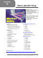
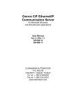
What is MiniOS7 Utility
MiniOS7 Utility is a tool for
configuring, uploading files to all
products embedded with
ICPDAS MiniOS7 with easiness
and quickness.
Note:Since version 3.1.1, the
Utility can allow users remotely
access the controllers
(7188E,8000E,…ect) through
the Ethernet
Functions
Supported connection ways
Including Frequently Used Tools
a. 7188XW
1. COM port connection (RS-232)
b. 7188EU
2. Ethernet connection (TCP & UDP)
c. 7188E
(Supported since version 3.1.1)
Maintenance
1. Upload file(s)
2. Delete file(s)
3. Update MiniOS7 image
Configuration
1. Date and Time
d. SendTCP
e. Send232
f. VxComm Utility
PC System Requirements
1. IBM compatible PC
2. Windows 95 /98/NT/2000/XP
Supported Products
2. IP address
1. 7188XA
3. COM port
2. 7188XB
4. Disk size (Disk A, Disk B)
3. 7188XC
Check product information
4. 7188EX series
1. CPU type
5. All i-8000 series
2. Flash Size
6. iView100
3. SRAM Size
7. uPAC-7186XB
4. COM port number
8. uPAC-7186EX
9. ET-6000 series
10. ET-7000 series
Download location:
http://ftp.icpdas.com.tw/pub/cd/8000cd/napdos/minios7/utility/minios7_utility/
8411/8811 User Manual, Version 1.0, January 2008, 8MS-002-10 --- 78
APPENDIX
D
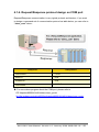
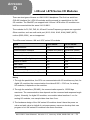
i-8K and i-87K Series I/O Modules
There are two types of buses on i-8411/i-8811 backplane. The first is a serial bus
(RS-485 interface) for i-87K I/O modules and the second is a parallel bus for i-8K
I/O modules. The MiniOS7,can support both i-8K and i-87K series I/O modules can
both be connected into the same i-8411/i-8811.
The modules for DI, DO, DIO, AI, AO and Counter/Frequency purpose are supported.
Other modules, such as multi-serial port (8112, 8144, 8142, 8144), MMC (8073),
motion (8090, 8091), are not supported.
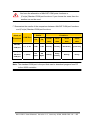
The differences between i-8K and i-87K series I/O modules:
Item
i-8K Series
i-87K Series
Microprocessor
No
Yes (8051)
Communication interface
Parallel bus (Note1)
Serial bus (Note2)
Communication speed
Fast
Slow
DI latched function
No
Yes
Counter input (for digital input module)
No
Yes (100 Hz)
Power on value
No
Yes
Safe value
No
Yes
Host watchdog
No
Yes
Module watchdog
No
Yes
Programmable slew-rate for AO module No
Yes
Note:
1. Through the parallel bus, the CPU can communicate with I/O modules very fast, for
digital I/O modules, the communication time takes 0.005 ~ 0.010 ms, for analog
I/O modules, it depends on the modules.
2. Through the serial bus (RS-485), the communication speed is 115200 bps
maximum. The communication time depends on the command and response length
(bytes). Normally, for digital I/O modules, one module takes less then 1 ms. for
analog I/O modules, one sample takes less than 2 ms.
3. The hardware design of the i-8K series I/O modules doesn’t have the power on
value and safe value in default of a microprocessor, users can develop their own
program to let i-8K series I/O modules have these functions.
8411/8811 User Manual, Version 1.0, January 2008, 8MS-002-10 --- 79
APPENDIX
E
More Compiler Settings
This section describes the setting of the following compilers:
Turbo C 2.01 Compiler
BC++ 3.1 IDE
MSC 6.00 Compiler
MSVC 1.50 Compiler
E.1. Turbo C 2.01 Compiler
You have a couple of choices here, you can:
1:Using a command line
For more information, please refer to
CD:\8000\NAPDOS\8000\841x881x\Demo\hello\Hello_C\gotc.bat
tcc -Ic:\tc\include -Lc:\tc\lib hello1.c ..\..\lib\8000e.lib
2:Using the TC Integrated Environment
Step 1:Executing the TC 2.01
Step 2:Editing the Project file
Adding the necessary library and file to the project
8411/8811 User Manual, Version 1.0, January 2008, 8MS-002-10 --- 80
Step 3:Save the project and entering a name, such as LED.prj
Step 4:Load the Project
Step 5:Change the Memory model (Large for 8000e.lib) and set the Code
Generation to 80186/80286
8411/8811 User Manual, Version 1.0, January 2008, 8MS-002-10 --- 81
Step 6:Building the project
8411/8811 User Manual, Version 1.0, January 2008, 8MS-002-10 --- 82
E.2. BC++ 3.1 IDE
Step 1:Executing the Borland C++ 3.1
Step 2:Creating a new project file (*.prj)
Step 3:Add all the necessary files to the project
8411/8811 User Manual, Version 1.0, January 2008, 8MS-002-10 --- 83
Step 4:Change the Memory model (Large for 8000e.lib)
Step 5:Set the Advanced code generation options and Set the Floating Point to
Emulation and the Instruction Set to 80186
8411/8811 User Manual, Version 1.0, January 2008, 8MS-002-10 --- 84
Step 6:Set the Entry/Exit Code Generation option and setting the DOS standard
Step 7:Choosing the Debugger…and set the Source Debugging to None
8411/8811 User Manual, Version 1.0, January 2008, 8MS-002-10 --- 85
Step 8:Make the project
8411/8811 User Manual, Version 1.0, January 2008, 8MS-002-10 --- 86
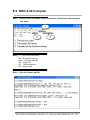
E.3. MSC 6.00 Compiler
Step 1:In the source file folder, create a batch file called Gomsc.bat using the
text editor
Note:/C:Don't strip comments
/Gs:No stack checking
/Fpa:Calls with altmath
/Fm:[map file]
/G1:186 instructions
/AL:large model
Step 2:Run the Gomsc.bat file
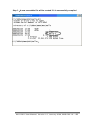
8411/8811 User Manual, Version 1.0, January 2008, 8MS-002-10 --- 87
Step 3:A new executable file will be created if it is successfully compiled
8411/8811 User Manual, Version 1.0, January 2008, 8MS-002-10 --- 88
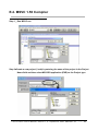
E.4. MSVC 1.50 Compiler
Step 1:Run MSVC.exe
Step 2:Create a new project (*.mak) by entering the name of the project in the Project
Name field and then select MS-DOS application (EXE) as the Project type
i-8 411 /i-8811 Us er ’s Man ua l , Vers io n 1 .0 ., Se p tember 2 007 , 8MS- 001- 10
---- -
89
Step 3:Add the user's program and the necessary library files to the project
Step 4:Set the Code Generation on the Compiler.
i-8 411 /i-8811 Us er ’s Man ua l , Vers io n 1 .0 ., Se p tember 2 007 , 8MS- 001- 10
---- -
90
Step 5:Change the Memory model (large for 8000e.lib)
Step 6:Remove the xcr, afxcr library from the Input Category
i-8 411 /i-8811 Us er ’s Man ua l , Vers io n 1 .0 ., Se p tember 2 007 , 8MS- 001- 10
---- -
91
Step 7:Remove the OLOGO option from the miscellancous Category.
Step 8:Rebuild the project
i-8 411 /i-8811 Us er ’s Man ua l , Vers io n 1 .0 ., Se p tember 2 007 , 8MS- 001- 10
---- -
92
APPENDIX
F
Application of RS-485 Network
The RS-485 length can be up to 4000 ft or 1.2 km over a single set of twisted–pair
cables, if the RS-485 network is over 4000 ft or 1.2Km, the RS-485 repeater must be
added to extend the RS-485 network.
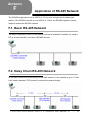
F.1. Basic RS-485 Network
The basic component of the RS-485 network consist of a Master Controller (or using a
PC as a host controller), and some RS-485 devices.
F.2. Daisy Chain RS-485 Network
All RS-485 devices are wired directly to the main network, If the network is up to 1.2 Km,
it will need a repeater (7510 series) to extend the network length.
i-8 411 /i-8811 Us er ’s Man ua l , Vers io n 1 .0 ., Se p tember 2 007 , 8MS- 001- 10
---- -
93
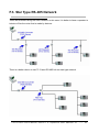
F.3. Star Type RS-485 Network
There are branches along the main network. In this case, it is better to have a repeater to
isolate or filter the noise that is made by devices.
There is a better choice to use 7513 as a RS-485 hub on start type network.
i-8 411 /i-8811 Us er ’s Man ua l , Vers io n 1 .0 ., Se p tember 2 007 , 8MS- 001- 10
---- -
94
F.4. Random RS-485 Network
There are branches along the main wire. In this case, it is better to have a repeater to
isolate or filter the noise that is made by devices.
i-8 411 /i-8811 Us er ’s Man ua l , Vers io n 1 .0 ., Se p tember 2 007 , 8MS- 001- 10
---- -
95
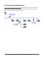
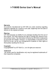
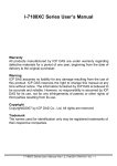
F.5. Pull-High/Pull-Low Resistor
There must be having one master to have a pull-high/pull-low resistor in the same network.
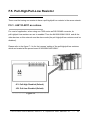
F.5.1. i-8411/i-8811 as a slave
For most of application, when using one 7520 series as RS-232/485 converter, its
pull-high/pull-low resistors are set to enabled. Then the 8410/8810/8411/8811 and all the
other devices on this network must be slave mode (the pull-high/pull-low resistors must be
disabled).
Please refer to the figure F-1 to for the jumpers’ setting of the pull-high/pull-low resistors
which are located at the power board of 8410/8810/8411/8811.
JP1: Pull-High Disabled (Default)
JP2: Pull-Low Disabled (Default)
Figure F-1
i-8 411 /i-8811 Us er ’s Man ua l , Vers io n 1 .0 ., Se p tember 2 007 , 8MS- 001- 10
---- -
96
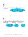
If there are repeaters on the RS-485 network, there will be pull-high/pull-low resistors
on both sides of the repeaters (i-7510)
i-8 411 /i-8811 Us er ’s Man ua l , Vers io n 1 .0 ., Se p tember 2 007 , 8MS- 001- 10
---- -
97
F.5.2. i-8411/i-8811 as a Master
When one of 8410/8810/8411/8811 is set to master, then all the other devices on the same
network must be slave mode. then the master one’s (8410/8810/8411/8811)
pull-high/pull-low resistors have to adjusted to enabled.
Please refer to the Figure F-2 to for the jumpers’ setting of the pull-high/pull-low resistors
which are located at the power board of 8410/8810/8411/8811.
JP1: Pull-High Enabled
JP2: Pull-Low Enabled
Figure F-2
i-8 411 /i-8811 Us er ’s Man ua l , Vers io n 1 .0 ., Se p tember 2 007 , 8MS- 001- 10
---- -
98
APPENDIX
G
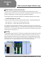
How to prevent illegal software copy
64-bit hardware unique serial number
The i-8411/i-8811 is equipped with a 64-bit hardware serial number onboard, each
hardware serial number is unique and individual. The application software can check this
number for illegal copies. It is the most low cost protection mechanism.
The following function is declared in 8000E.H for reading the hardware serial number:
int GetSerialNumber(char *Serial);
The serial number length is 8 bytes, SystemSerialNumber[0] ~ SystemSerialNumber[7].
If the values are “-1” means can not find the serial number.
If the values are “-2” means serial number CRC check error.
If the application program read and check the hardware serial number, this program will
be executed in this i-8411/i-8811 only. If someone copies this program and move to another
i-8411/i-8811 or other controller, this program will read and check hardware serial number
and then get error and stop to run.
AsicKey
The backplane supports AsicKey. The AsicKey is equipped with a complex state machine
checking and 128 bytes of private data for validation checking. It provides very strong
protection against the illegal copies. Every legal user has a unique AsicKey and unique
software library, the user can check this key themselves, the MiniOS7 will check the key
automatically. So it is nearly impossible to remove the AsicKey protection.
i-8 411 /i-8811 Us er ’s Man ua l , Vers io n 1 .0 ., Se p tember 2 007 , 8MS- 001- 10
---- -
99