1
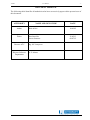
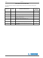
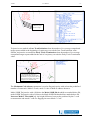
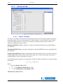
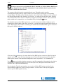
RASS-R - TRACKAN User Manual Edition : Edition Date : Status : 6 31-MAY-13 Released Issue DOCUMENT IDENTIFICATION SHEET DOCUMENT DESCRIPTION Document Title RASS-R TRACKAN Module Document Reference Number 6 EDITION : EDITION DATE : 31-MAY-13 Abstract The RASS-R TRACKAN Module User manual describes the TRACKAN module and the software components of which it is built. TRACKAN interfaces with the RASS-R Data Handler Module (DHM) and therefore you should be familiar with that material. This manual supplements the RASS-R Toolbox manual, and assumes that you are familiar with that material. You should also be familiar with the operation of your computer, your computer’s operating system and the IntersoftElectronics specific hardware for Radar Data I/O. TRACKAN BDS Register Analysis CONTACT PERSON : Keywords MODE-S Pd Dirk De Bal TEL : +32 14 231811 DOCUMENT STATUS AND TYPE STATUS Working Draft Draft Proposed Issue Released Issue CATEGORY Executive Task Specialist Task Lower Layer Task ELECTRONIC BACKUP IE-UM-00032-006 TRACKAN.doc INTERNAL REFERENCE NAME : HOST SYSTEM MEDIA SOFTWARE(S) Windows XP SP3 Type : Word XP Media Identification : Trackan User Manual -3- DOCUMENT APPROVAL The following table identifies all authorities who have successively approved the present issue of this document. AUTHORITY NAME AND SIGNATURE DATE Author Dirk de Bal 10/02/05 Editor Bert Sauviller Jeroen Janssens 31/05/13 09/07/12 Director ATC Director Software Department Ing. M. Vanuytven Ir. E. Moons Trackan User Manual -4- DOCUMENT CHANGE RECORD The following table records the complete history of the successive editions of the present document. REASON FOR CHANGE SECTIONS PAGES AFFECTED EDITION DATE 0.1 10/02/05 New document All 0.2 24/11/05 Update with new features All 1.1 29/06/07 Layout changed from figure 3 All 1.2 26/06/08 3 13/10/09 4 06-JAN-11 Review of chapter 4 and 6 Chapter 7 Tutorial removed Filename changed; Manual up to date with TRACKAN v1.3.6 Manual up to date with TRACKAN v1.3.7 5 09-JUL-12 Editorial changes 6 31-MAY-13 User manual up to date with TRACKAN version 1.3.8; Logo updated None None P13, P15 None Trackan User Manual -5- TABLE OF CONTENTS 1. INTRODUCTION ............................................................................................................................................. 8 1.1. 2. GENERAL OVERVIEW ................................................................................................................................. 9 2.1. 2.2. 2.3. 2.4. 2.5. 3. TRACKAN AS PART OF RASS-R .............................................................................................................. 9 TRACKAN PROCESSING UNIT ................................................................................................................... 9 TRACKAN CONFIGURATION ..................................................................................................................... 9 TRACKAN VIEWERS ............................................................................................................................... 10 NETWORK OPERATION .............................................................................................................................. 10 INSTALLATION, VERIFICATION AND STARTUP ............................................................................... 11 3.1. 3.2. 4. BENEFITS AND POSSIBILITIES OF THE SYSTEM ............................................................................................ 8 RUNNING THE DHM BACKGROUND SERVER............................................................................................. 11 RUNNING THE TRACKAN PROCESSING UNIT .......................................................................................... 11 CONFIGURATION ........................................................................................................................................ 12 4.1. ADD/EDIT PROCESSING THREADS ............................................................................................................. 13 4.1.1. General tab ......................................................................................................................................... 13 4.1.2. Process tab.......................................................................................................................................... 16 4.1.3. Advanced Tab ..................................................................................................................................... 20 4.1.4. Alarm tab ............................................................................................................................................ 22 4.1.5. Radar’s Digest tab .............................................................................................................................. 23 4.1.6. Distribution tab ................................................................................................................................... 23 4.2. SAVE/LOAD CONFIGURATIONS ................................................................................................................. 23 5. RUNNING ....................................................................................................................................................... 24 5.1. 5.2. 5.3. 6. RECALCULATION ...................................................................................................................................... 25 ON-LINE HELP .......................................................................................................................................... 26 QUITTING TRACKAN ............................................................................................................................. 26 SOFTWARE COMPONENTS ...................................................................................................................... 27 6.1. TRACKAN MAIN GUI ............................................................................................................................ 27 6.2. CONFIGURATION WINDOW........................................................................................................................ 27 6.3. RECALCULATION WINDOW ....................................................................................................................... 28 6.4. VIEWERS .................................................................................................................................................. 28 6.4.1. TRACKAN Main Viewer ..................................................................................................................... 29 6.4.2. TRACKAN History Viewer.................................................................................................................. 32 6.4.3. TRACKAN Histogram Viewer............................................................................................................. 33 6.4.4. TRACKAN BDS Register Viewer ........................................................................................................ 33 Trackan User Manual -6- TABLE OF FIGURES Figure 1-1: TRACKAN data flow ................................................................................................................................. 8 Figure 2-1: RASS-R Structure ...................................................................................................................................... 9 Figure 3-1: TRACKAN main GUI in compact mode .................................................................................................. 11 Figure 3-2: TRACKAN main GUI in full mode .......................................................................................................... 11 Figure 4-1: TRACKAN configuration window. .......................................................................................................... 12 Figure 4-2: Menu bar ................................................................................................................................................. 13 Figure 4-3: Preferences - General tab ....................................................................................................................... 15 Figure 4-4: Preferences - Process tab ........................................................................................................................ 16 Figure 4-5: Enabled (Bertem) and Disabled (St-Hubert) thread ............................................................................... 16 Figure 4-6: Different modes ....................................................................................................................................... 16 Figure 4-7: Radar data format ................................................................................................................................... 17 Figure 4-8: Track Extrapolate=3 ............................................................................................................................... 17 Figure 4-9: Track Extrapolate=5 ............................................................................................................................... 18 Figure 4-10: Late Track initiation .............................................................................................................................. 18 Figure 4-11: Viewer display options .......................................................................................................................... 19 Figure 4-12: Preferences - Advanced tab................................................................................................................... 20 Figure 4-13: Viewer display options .......................................................................................................................... 21 Figure 4-14: Alarm configuration window ................................................................................................................. 22 Figure 5-1: Work in progress information. ................................................................................................................ 24 Figure 5-2: Work done information............................................................................................................................ 24 Figure 5-3: Recalculation window. ............................................................................................................................ 25 Figure 6-1: TRACKAN Main GUI in action ............................................................................................................... 27 Figure 6-2: TRACKAN Configuration window .......................................................................................................... 27 Figure 6-3: TRACKAN Recalculation window ........................................................................................................... 28 Figure 6-4: Viewer selection drop down menu........................................................................................................... 28 Figure 6-5: TRACKAN History window ..................................................................................................................... 29 Figure 6-6: Legend and statistics ............................................................................................................................... 30 Figure 6-7: Detailed PPI view with label and corresponding ASTERIX data ........................................................... 31 Figure 6-8: TRACKAN History window ..................................................................................................................... 32 Figure 6-9: TRACKAN Histogram window ................................................................................................................ 33 Figure 6-10: TRACKAN BDS register window .......................................................................................................... 33 Figure 6-11: TRACKAN detailed BDS register window ............................................................................................ 34 Figure 6-12: TRACKAN BDS Register Timeline representation ................................................................................ 35 Figure 6-13: ELS/EHS detail...................................................................................................................................... 35 TABLE OF TABLES Table 1: TRACKAN TPC/IP Ports ............................................................................................................................. 10 Trackan User Manual -7- CONVENTIONS USED IN THIS MANUAL The following conventions are used in this manual: Note: This icon to the left of bold italicized text denotes a note, which alerts you to important information. Caution: This icon to the left of bold italicized text denotes a caution, which alerts you to the possibility of data loss or a system crash. Warning: This icon to the left of bold italicized text denotes a warning, which alerts you to the possibility of damage to you or your equipment. Trackan User Manual -8- 1. Introduction TRACKAN is a 24h/7d real time radar data monitoring and analysis tool. It calculates Pd and accuracy for individual trajectories. It has full Mode S capabilities and therefore can perform BDS register analysis. TRACKAN uses the RASS-R Data Handler Module (DHM) as radar data I/O. All results are stored in format files. Figure 1-1: TRACKAN data flow TRACKAN consists out of a central processing unit and several viewers. 1.1. Benefits and possibilities of the system 24/7d radar data monitoring and analysis; no snapshot analysis. Real time; immediate response to problems. Multiple radar data streams may be processed sequentially. The same input data may be processed in different ways and be presented in different views. Analysis based on individual trajectories; identify problematic transponders. Full Mode S capabilities; includes BDS register analysis. Client specific demands are easily integrated. (For example: Status reports and alarm signalling via e-mail, pager, mobile phone messages or www.) Multiple history windows for long/short term trend analysis. Trackan User Manual -9- 2. General Overview 2.1. TRACKAN as part of RASS-R Figure 2-1: RASS-R Structure The radar data that is converted/corrected/modified by the Data Handler Module is redirected to different components of the RASS-R configuration. One of these RASS-R components is TRACKAN. TRACKAN performs radar data quality analysis. 2.2. TRACKAN processing unit The TRACKAN processing unit also acts as the main GUI to operate the TRACKAN software. All features are accessed using this GUI. TRACKAN configuration is done through one Configuration window. Radar data analysis results can be presented using different viewers. 2.3. TRACKAN configuration All configuration of TRACKAN is done using the Configuration window. The Configuration window can be accessed through the TRACKAN GUI. The configuration window allows you to create, edit and enable/disable processing threads in TRACKAN. The last used configuration is always stored and used upon start-up. A configuration includes the desktop layout of the different available windows. Trackan 2.4. User Manual - 10 - TRACKAN viewers TRACKAN has several viewers to present the results of the radar data analysis to the user. Each viewer can be opened multiple times to represent the results in different views. TRACKAN viewers communicate with the TRACKAN processing unit via data containers. A data container is a temporary storage place for the most recent results of the radar data analysis. 2.5. Network operation TRACKAN uses several TCP/IP ports for different purposes, it is important that these ports are free for use on the target system. The following table shows an overview of the ports used by the TRACKAN. Table 1: TRACKAN TPC/IP Ports Port Number 5570 Used by TRACKAN Usage Inter-application communication with DHM Trackan User Manual - 11 - 3. Installation, verification and startup 3.1. Running the DHM background server You might need to be logged on as an administrator or a member of the Administrators group in order to perform some tasks. In case that the TRACKAN performs analysis on real time data, the Data Handling Module background server needs to be running before the TRACKAN software is started. The Data Handling Module background server can be started using the Windows XP services management console. For more details, please consult the DHM user manual. If the TRACKAN performs analysis on data that was already recorded, it is not necessary to have the DHM running. 3.2. Running the TRACKAN Processing unit The TRACKAN module can be started from the RASS-R toolbox or the Windows Start Menu. The following window (or similar) will appear. Figure 3-1: TRACKAN main GUI in compact mode This is the TRACKAN processing unit and main GUI used to operate the TRACKAN tool. The last used configuration is automatically loaded upon start-up. By clicking the button (lower right corner) the TRACKAN main GUI is displayed in full mode. Figure 3-2: TRACKAN main GUI in full mode Trackan User Manual - 12 - 4. Configuration Configuration of the TRACKAN tool is done with the Configuration window which is evoked by clicking the button in the TRACKAN main GUI. The following window appears: Figure 4-1: TRACKAN configuration window. Only the first time after installation, no processing threads are defined. All other times, the current processing threads are shown in the configuration window. A processing thread can be considered a set of parameters that will be applied to a radar data stream in order to perform an analysis. Multiple processing threads can be defined, they will be executed sequentially. One radar data stream can be used in different processing threads to obtain different analysis figures. Trackan User Manual 4.1. - 13 - Add/Edit processing threads Figure 4-2: Menu bar A new processing thread can be added by clicking the button. Notice that the “new” thread is added to the list at the right hand side of the configuration window. The settings of the last used thread (or default) are automatically used for the new thread. When multiple threads are defined, use the threads list to select the one of interest by clicking on the corresponding item. Clicking the button deletes the selected processing thread from the list. Clicking the button copies the selected processing thread into memory. Clicking the button pastes the previously copied processing thread into the selected processing thread. Clicking the button clears all processing threads from the list. Use the four tabs to navigate through the different thread configuration parameters. 4.1.1. General tab The general tab contains parameters that are typical for a specific radar data stream: site parameters, radar data source path and coverage maps. 4.1.1.1. Site The name of the site will be used throughout the TRACKAN tool to identify a specific processing thread. It is advised to choose this name so that it can easily be interpreted. Longitude and latitude are in the following format; °:MM:SS.ssss, east and north being positive, west and south being negative. The altitude is the altitude of the antenna above mean sea level in WGS 84. The revolution time is an important parameter for the trajectory reconstruction and therefore needs to be accurate. (Choose 1 second for ADS-B data analysis) Minimum elevation, maximum elevation, minimum range, maximum range, minimum altitude and maximum altitude are used to define the general coverage volume boundaries. Target reports located outside this coverage volume are not taken into account during the analysis. Trackan User Manual 4.1.1.2. - 14 - Data source The data source defines the path where TRACKAN retrieves the radar data to be processed. This path should contain an archive folder created by the DHM. The format of the archive files should be the .D6 format. For more information on how to create a .D6 format archive, please consult the DHM user manual. When you click the open button to the folder where all the .D6 files are stored. , a dialog to browse follows. Browse It is important to select a folder or group of folders that contains the .D6 files. You cannot select an individual .D6 file! When the path to the Data Source is correctly filled in, you should see all the files in the Recalculation Window. (See paragraph 5.1) 4.1.1.3. DTED DTED screening maps are calculated by the RASS-R Coverage Map Calculator (CMC). They originate from Digital Terrain Elevation Data with a resolution of 3 Arcsec. For more details on how to create DTED screening maps, please consult the corresponding user manual. Click the button to browse for a DTED screening map. DTED screening files have a .hrscr extension. The default path for the DTED screening maps in RASS-R is: C:\Program Files\Intersoft Electronics\RASS\Maps\DTED Use the checkbox to enable/disable the use of the DTED screening map in the TRACKAN tool. The visibility offset angle value is added to the DTED screening map angle to reduce/increase the DTED screening angles. Trackan User Manual 4.1.1.4. - 15 - SALADT SALADT screening files can be imported in the TRACKAN tool. Click the button to browse for a SALADT screening map. SALADT screening files have a .scr extension. Use the checkbox to enable/disable the use of the SALADT screening map in the TRACKAN tool. The visibility offset angle value is added to the SALADT screening map angle to reduce/increase the SALADT screening angles. Refer to [2] for further details. 4.1.1.5. SMGET SMGET cluster maps can be imported in the TRACKAN tool. Click the button to browse for a SMGET cluster map. Use the checkbox to enable/disable the use of the SMGET cluster map in the TRACKAN tool. The value of the SCF cluster state is mandatory in order to use the SMGET cluster maps. Refer to the “Mode-S System Map Generator and Extractor Tool” on EUROCONTROL website for further details. 4.1.1.6. Blank Zones Blank zones are areas defined by the user to be excluded from the analysis. Use the checkbox to enable/disable the use of the blank zones in the TRACKAN tool. There is no limit on the number of blank zone within a processing thread. A blank zone is defined as a cubical volume (X min, X max, Y min, Y max, Z min and Z max) within the general coverage volume. 4.1.1.7. Local Screening A local screening file is a tab separated file containing a table of the local screening angle versus azimuth. (For example if you do not have a DTED or SALADT file) Finally, the result can be as follows: Figure 4-3: Preferences - General tab Trackan User Manual 4.1.2. - 16 - Process tab The processing tab contains parameters that are typical for a specific way of processing the radar data: parameters and exclude list. Figure 4-4: Preferences - Process tab 4.1.2.1. Parameters A processing Thread can be enabled/disabled using the processing selector. A disabled processing thread is not executed during the processing, but the processing parameters remain available for later use. Figure 4-5: Enabled (Bertem) and Disabled (St-Hubert) thread When available it is advised to select Time of Detection for timing purposes. Time of Recording includes the processing and transmission delay and can possibly be less accurate for the analysis. Use the Mode selector to excluded/included specific types of detection during the analysis: Figure 4-6: Different modes Detection types that are excluded are not taken into account during the processing and will be categorized as Non Initiated. The BDS Register Analysis can be enabled/disabled individually for each processing thread. Notice that enabling the BDS register analysis will increase the required processing time. Trackan User Manual - 17 - The Radar Data format can be Asterix or Aircat (2 possibilities). Figure 4-7: Radar data format Combine a number of files in order to have a bigger data set for the analysis. The combined files will act as a sliding window each time a new file becomes available. Because the analysis is trajectory based, it is advised to combine a number of files for a period equal to the average time a target spends in the coverage. Below the Minimum Track Length, a trajectory is not used in the processing. The individual target reports will be marked as not initialized in the TRACKAN Main Viewer. The Track Extrapolate parameter defines the number of extrapolated target reports added at the beginning and the end of each trajectory (for the extrapolation on the beginning of a track, you need to combine files. Otherwise the TRACKAN does not know whether the track really started or it is just present in this .D6 file). This extrapolation is done using the average speed and heading calculated with the last N target reports, N being the Extrapolation Window parameter. The extrapolated target reports are checked against the defined coverage volume and each extrapolated target report is marked as in/out coverage. Extrapolated target reports marked as in coverage are considered as missed by the radar and are taken into account during the analysis. (Red color in Viewer) 3 targets are added and judged out of coverage Figure 4-8: Track Extrapolate=3 Trackan User Manual - 18 - 5 targets are added and judged out of coverage Figure 4-9: Track Extrapolate=5 Trajectories are marked as Late Track Initiation when the number of in coverage extrapolated target reports added at the beginning of a trajectory exceeds the Late Track Initiation value. Similar, trajectories are marked as Early Track Termination when the number of in coverage extrapolated target reports added at the end of a trajectory exceeds the Early Track Termination value. At the beginning of the track, 3 targets are extrapolated and judged as in coverage and therefore missed targets. This number (3) is greater than the Late Track Initiation number, so the track is displayed as Late Initiation track. Figure 4-10: Late Track initiation The Maximum Code Absence parameter is used to flag trajectories with at least the predefined number of consecutive Mode3/A code, mode C code or Mode S address absences. Mode S/SSR Trajectories with a Pd below the Mode S/SSR Pd threshold are marked below Pd, mode S/SSR Trajectories with a Pd above the Mode S/SSR Pd threshold are marked above Pd. Incorrect Mode C Threshold [m]: the height difference between the predicted by the C-code reconstruction and actual C-code for flagging incorrect Mode C Code. Trackan User Manual - 19 - Based on several parameters above, the results can be filtered with the Display functionality in the Viewer. (See paragraph 6.4.1) Figure 4-11: Viewer display options 4.1.2.2. Exclude list Use the exclude list to exclude specific trajectories from the analysis. Trajectories can be identified using a Mode S address [hex] or a Mode A code [oct]. Trackan User Manual 4.1.3. - 20 - Advanced Tab Figure 4-12: Preferences - Advanced tab 4.1.3.1. Object correlator The Object Correlator correlates the individual plots and tries to build tracks again, based on the parameters below. These correlated tracks are visible as the Nr. in the Trackan Viewer. In this way, the TRACKAN can be a reference for analysis for different radar sources which were influence of different tracker systems. Maximum MODE AC Gap: a parameter setting the maximum SSR trajectory gap bridged by the algorithm Maximum MODE S Gap: a parameter setting the maximum MODES trajectory gap bridged by the algorithm Origin Approach Range [NM]: the range band where the next plot can be expected to have any azimuth (applicable for the vicinity of the radar origin when a fast moving target may produce azimuth change of about 180 degrees or greater.) The following three parameters are designed to model the random azimuth error in general using the formula Az Az 0 ( R R0 ) Where R0 is the Range Offset [NM] Az 0 is the Random Azimuth Error [deg] is the Azimuth Error with Range [NM] Allowed Speed Jitter Factor: Trackan User Manual 4.1.3.2. Split Tracks Three following parameters are dedicated for detection of the split plots: Delta Azimuth [deg] Delta Range [NM] Delta Timestamp [s] Tracks that are assigned the label “Split Track” can be displayed with the following menu: (See paragraph 6.4.1) Figure 4-13: Viewer display options - 21 - Trackan User Manual 4.1.4. - 22 - Alarm tab The alarm tab contains settings to trigger alarms when certain predefined values are exceeded. Figure 4-14: Alarm configuration window Switch an individual alarm on/off by typing on or off in the corresponding table entry. Every parameter can have a target value and a limit value, the target value being the expected or desired value, the limit value being the alarm trigger value. When the target value is greater than the limit value, an alarm is triggered whenever the measured value is smaller than the limit value and this for a consecutive number of times equal to the Allowed value plus one. Explanation of the theoretical example as in the figure above: The target of Pd is 99.5%. When the Pd drops to 99.0% or lower for 4 consecutive scans (3+1), it will trigger an alarm The target of Missed targets is 5. When the number of missed targets increases till 10 or higher in one scan, it will trigger an alarm. Trackan User Manual 4.1.5. - 23 - Radar’s Digest tab This tab allows the user to accumulate a specific set of trajectories over a longer period. Use the filter/category controls to define a specific set of trajectories and check the box to enable the processing. All the trajectories that comply are stored in a separate file called Digest 1. This file has can be used as a data source in an extra processing thread allowing the automatic processing of the accumulated set of trajectories just as any of the other treads. 4.1.6. Distribution tab The distribution tab contains the information required to distribute the results of the radar data analysis according to the user’s needs. In the current version of the TRACKAN tool, the results can only be saved to disk. All other possibilities are for future developments. Click the button to browse for a destination path. Use the checkbox to enable/disable the saving of the result to disk. All results are stored in file format. 4.2. Save/Load configurations A complete configuration can be saved to disk by clicking the button. Notice that the TRACKAN main GUI also has this save configuration button. A complete configuration can loaded from disk by clicking the load configuration button. button. Notice that the TRACKAN main GUI also has this Trackan User Manual - 24 - 5. Running Running TRACKAN is done by pressing the button in the main GUI. TRACKAN will be idle until a file becomes available from the DHM. When a .D6 file is released by the DHM, processing by TRACKAN will start automatically. This process is repeated every time a new file is made available by the DHM. The processing status and progress can be monitored using the work in progress information. Figure 5-1: Work in progress information. This means that there is a processing delay on the results equal to the period of one file and that there is an update of the results every period of one file. Stopping TRACKAN is done by pressing the button. TRACKAN will always complete the work in progress before the processing is stopped. TRACKAN will resume with the next available file when the button is pressed. The combination of stop and restart will automatically clear all results from memory. This means that all history is cleared. Click the button to pause TRACKAN. TRACKAN will always complete the work in progress before the processing is paused. By clicking the file will be processed when it becomes available. button, the next and only the next Whenever a file is processed, an entry is put in the log. The status of the file is changed to done. Figure 5-2: Work done information. At any time, all results in memory can be cleared by clicking the effect as stopping and starting the TRACKAN tool. button. This has the same Trackan 5.1. User Manual - 25 - Recalculation While TRACKAN is running, any file that already has been processed can be re-processed at any time. Click the similar) will appear. button to open the Recalculation window. The following window (or Figure 5-3: Recalculation window. The thread selector can be used to select a specific thread for the recalculation. The path to the archive and a list of the available files is displayed. All files that are already processed are indicated by [Done]. Select the file of interest or shift-click for selecting multiple files. Alternatively, use the row of select buttons to define a specific selection range. Use the button to change the status of the selected files from [Done] to [To Do]. Use the button to change the status of the selected files from [To Do] to [Done]. Uncheck the Update checkbox when the results of the recalculation do not need to be added to the current analysis results (history). Trackan 5.2. User Manual - 26 - On-line help Clicking the format. button opens the on-line user manual. The on-line user manual is in PDF Clicking the button opens the context help window. Position the cursor over a control to get context help for that control. 5.3. Quitting TRACKAN Click the button to quit TRACKAN. The current configuration will automatically be stored and re-used as default configuration next time. All open window will be closed automatically and their layout is saved as part of the configuration. The layout (position and settings) of all the open TRACKAN windows will be stored as part of a configuration. The content of the windows is NOT part of a configuration. Trackan User Manual 6. Software components This chapter provides an overview of all the available software components in TRACKAN. Some of them have already been described in the paragraphs above. 6.1. TRACKAN Main GUI Figure 6-1: TRACKAN Main GUI in action The use of the TRACKAN main GUI is described in paragraph 5. 6.2. Configuration window Figure 6-2: TRACKAN Configuration window The use of the TRACKAN configuration window is described in paragraph 4. - 27 - Trackan 6.3. User Manual - 28 - Recalculation window Figure 6-3: TRACKAN Recalculation window The use of the TRACKAN recalculation window is described in paragraph 5. 6.4. Viewers The last processed set of files for each processing thread is available for real time viewing and analysis. They remain available until the next set of files is processed. This way the latest up-todate information is always ready for viewing and analysis. Several viewers are at the disposal of the user to monitor and verify these analysis results in real time. Each type of viewer can be opened multiple times with different settings. This allows the user to represent the results in different ways. All Viewers can be launched from the TRACKAN Main GUI by using the Figure 6-4: Viewer selection drop down menu The following paragraphs explain the use of these viewers in more detail. drop down menu. Trackan User Manual 6.4.1. - 29 - TRACKAN Main Viewer The TRACKAN Main Viewer always displays the latest processed data set for a specific processing thread. Whenever a new data set is processed, the TRACKAN Main viewer is updated automatically. There is an entry in the table for every individual trajectory encountered in the analysis. Individual trajectories can be enabled/disabled by right clicking the trajectory of interest and selecting Enable/Disable from the popup menu. The symbol in front of the trajectory will change from to when it becomes disabled. Disabled trajectories are not shown in the PPI display. The content of the table can be customised by the user. The table can be sorted in ascending/descending order by clicking on the corresponding column header in the table. The table can be filtered using the Filter function. A specific set of transponders can be selected by using the Display selector. The customised table/PPI content can be exported to a .csv/.bmp formatted file by clicking the button and selecting the appropriate menu item. Figure 6-5: TRACKAN History window Trackan User Manual - 30 - The PPI display below the table show the table content in a graphical representation. Only trajectories listed in the table are drawn in the PPI display. The trajectory corresponding with the selected entry of interest in the table is colored blue in the PPI display. The TRACKAN Main Viewer legend is as follows: : coasted target reports (= miss reported by the radar) : selected trajectory : not initialized (meaning assigned by TRACKAN, based on minimum trajectory length not reached) : reported target in coverage linked to trajectory (meaning assigned by TRACKAN, based on object correlator parameters) : reported target out coverage linked to trajectory (meaning assigned by TRACKAN, based on coverage file) : Missed in coverage by the radar and added by the TRACKAN analysis. : Missed out coverage by the radar and added by the TRACKAN analysis. Use the corresponding checkboxes display. to add/deleted specific data sets from the PPI Figure 6-6: Legend and statistics Explanation about the different figures: The number of reported targets is split in number of coasted, not initiated and linked targets, both expressed in absolute and per cent value: 62742=894+804+61044 or 100%=1.4%+1.3%+97.3% 7134 targets or 11.4% from 62742 reported targets are linked but out of coverage. 62742-(894+804+7134)=53910 are used for the Pd calculation Used-missed=53910-205 gives a Pd of 99.621% from 53910. If the number of used targets is zero (because for example all targets are assumed as out of coverage) no statistics will be calculated. Trackan User Manual - 31 - Click the button to view the full scale PPI. Click the button to automatically zoom to the selected trajectory +10%, or zoom stepwise. Click the / to button to display the selected trajectory only. Click the button to lock the cursor onto the selected trajectory. Click the button to give each trajectory a different color. Click the button to display a label attached to the cursor. Press the space bar to rotate the label content. Click to enable the cursor, click the button to center the cursor and to drag the PPI view. Click to enable the view select window. Use the standard Labview menus for scaling, precision, color etc. Figure 6-7: Detailed PPI view with label and corresponding ASTERIX data Trackan User Manual 6.4.2. - 32 - TRACKAN History Viewer Figure 6-8: TRACKAN History window The top row selectors allow any parameter from any processing thread to be displayed in the history window. Every set of processed files adds an entry in the histogram window. One history window can display up to three different parameters from on processing thread or one parameter from three different processing threads or any combination of the above. Whenever alarm levels are defined in the configuration window (see paragraph 4) they will be displayed in the history window as a green (target value) and a red (limit value) line. Alarm settings are only applicable for the top row selectors. This means that there can only be one alarm setting active for each history window. When an alarm stage is reached, the history window will turn red and the title bar will flash as long as the alarm stage is maintained. When the alarm stage is released, the window will stay red as an indication that an alarm stage has been encountered. Click the button to reset the alarm conditions. The content of the history window can be logged to disk (.csv format) by checking the box. Every increment in the history window is added to log file. This way, the log file is always updated with the latest information. Switching on the log function will allow the user to browse for a destination file. Trackan User Manual 6.4.3. - 33 - TRACKAN Histogram Viewer Figure 6-9: TRACKAN Histogram window The top row selectors allow any parameter from any processing thread to be displayed in the histogram window. On the right hand side the statistics calculated from the histogram are shown. A cursor can be put on the histogram to query specific values in more detail. 6.4.4. TRACKAN BDS Register Viewer Whenever Mode S data is available (ASTERIX cat048), the BDS register analysis is automatically enabled. Select the thread of interest with the thread selection menu. Figure 6-10: TRACKAN BDS register window There is an entry in the table for every Mode S address encountered in the analysis. Trackan User Manual - 34 - The latest reported aircraft ID, BDS10, BDS17, BDS1D, ACAS RA, BDS40, BDS50 and BDS60 are displayed in the table. This information is only available when it is present in the ASTERIX cat048 radar data stream. The content of the table can be customised by the user. The table can be sorted in ascending/descending order by mode S address or aircraft ID by clicking the corresponding column header. The table can be filtered using the value of the mode S Address or the content of the aircraft ID using the Filter function. Use a point (.) as wild card for the filter value. Specific set of transponders can be shown or hidden by using the two Display selectors. The customised table content can be exported to a .csv formatted file by clicking the button. The detailed content of the BDS registers for a specific transponder (Mode S address) can be displayed by right clicking on the entry of interest. A popup menu appears that allows the user to open a BDS register float window containing the detailed and translated BDS register content for that specific Mode S address. Figure 6-11: TRACKAN detailed BDS register window Click one of the buttons to view more details of the BDS register content or right click on the window and select “open all” from the popup menu. From the same popup menu, the detailed BDS register content of an individual transponder can be exported to a .csv formatted file. Use the button to lock the window content to a specific transponder. Alternatively, the window content will be updated according to the selection (blue line). Multiple detailed BDS content windows can be opened simultaneously. By selecting the Timeline presentation, an overview of all the BDS register activity for the selected Mode S address is given in a single window. Use the cursor in the top left graph to select a specific BDS register activity. Trackan User Manual - 35 - Figure 6-12: TRACKAN BDS Register Timeline representation Below the table a general overview of the BDS register content is displayed. Each time two values are presented: absolute [#] and relative [%]. Use the tabs to get more detailed information for each of the BDS registers and their content. 6.4.4.1. ELS/EHS This tab calculates the percentage of Elementary Surveillance (ELS) compliant and Enhanced Surveillance compliant (EHS) Mode S transponders. The ELS/EHS criteria are according to the latest EUROCONTROL rules on ELS/EHS. Figure 6-13: ELS/EHS detail These rules can be loosened or tightened by double clicking on the corresponding table entry. Disabled rules are not taken into account for the calculations. Trackan User Manual - 36 - GLOSSARY A ACP ARP Asterix Asterix Data Block Asterix Record Azimuth Count Pulse. Azimuth Reference or Reset Pulse. All Purpose Structured Eurocontrol Surveillance Information Exchange Unit of information seen by the application as a discrete entity by its contents. A Data block contains one or more Record(s) containing data of the same category. A collection of transmitted Data Fields of the same category. B Baud Unit of signal frequency in signals per second. Not synonymous with bits per second since signals can represent more than one bit. Baud equals bits per second only when the signal represents a single bit. CAT001 Monoradar Data Target Reports, from a Radar Surveillance System to an SDPS (plots and tracks from PSRs, SSRs, MSSRs, excluding Mode S and ground surveillance) Monoradar Service Messages (status, North marker, sector crossing messages) Monoradar Service Messages, next version of CAT002 Monorader Data Target Reports, next version of CAT001 The probability that a variable takes a value less than or equal to a certain value C CAT002 CAT034 CAT048 Cumulative Distribution D D6 Data bits DCE EHS ELS DTE DTED Intersoft Electronics internal data Radar data format, plot or track based. In data communications, the number of bits used to send each character, not including any added timing or error checking bits Data Communications Equipment. The local and/or remote modem. A DCE is usually connected to a DTE. Enhanced Surveillance Elementary Surveillance Data Terminal Equipment. The computer or terminal, either local (yours), or the remote (the one you’re communicating with). A DTE is usually connected to a DCE. Digital Terrain Elevation Data E EDR EDR V2 Ethernet Intersoft Electronics internal data format for record based data. Also stands for Extended Data Recorder, a device for generating and capturing serial data. Second version of the EDR format. A network specification developed by DEC, Intel, and Xerox which provides anywhere from 10 megabits to 1000 megabits per second transmission speeds. F Flow control A method of controlling when information is sent Hex Hexadecimal. 16 based numbering system ranging from 0 to F I/O Input/Output. The transfer of data to or from a computer system involving communications channels, operator interface devices, and/or data acquisition and control interfaces. MB Mode S Megabytes of memory. Selective addressing secondary surveillance radar technique Oct Octal value. 8 based numbering system ranging 0 to 7 . A path can be described as a file’s address on your file system, describing where the file lives: An absolute path gives the complete path, starting at the root directory, or the very top of the filesystem; A relative path looks for a file from the directory you are currently in down. H I M O P Path R Record RS323, RS422 A collection of data forming a complete message. The Electronics Industry Association (EIA) has produced standards for RS232 and RS422 that deal with data communications. Trackan User Manual - 37 - S SAC SALADT SASS-C SIC SMGET System Area Code, used in Asterix data. Used by SASS-C Tool for visibility computation Surveillance Analysis Support System for ATC-Centre System Identification Code, used in Asterix data. Mode-S System Map Generator and Extractor Tool Timeout A timeout occurs when a device has waited too long for another device to send or receive a transmission. UAP UDP UTC User Application Profile, used in Asterix data for assigning Data Items to Data Fields. User Datagram Protocol. A connectionless, unreliable Internet protocol. Coordinated Universal Time. WGS-84 World Geodetic System 1984 T U W Trackan User Manual REFERENCED DOCUMENTS Reference [1] [2] Document Coverage Map Interface Control Document for POEMS stations SASS-C user manual - 38 - Trackan User Manual - 39 - INDEX --A-Add threads ............................ 12 Alarm ............................... 15, 23 Limit ........................... 16, 23 Traget .......................... 16, 23 --B-background server.................. 11 BDS Register ......................... 24 Benefits .................................... 8 Blank Zones ........................... 13 --C-Color ...................................... 22 Configuration ......................... 12 Alarm ................................ 15 Blank Zones ...................... 13 Data Source ....................... 13 Distribution ....................... 16 DTED................................ 13 Exclude List ...................... 15 Parameters......................... 14 SALADT........................... 13 Site .................................... 12 SMGET ............................. 13 CSV Format 8, 16, 21, 23, 24, 25 --D-- Exclude List ........................... 15 --G-General Overview .................... 9 TRACKAN as part of the RASS-R .......................... 9 TRACKAN Configuration .. 9 TRACKAN Processing Unit9 TRACKAN Viewers ........... 9 Glossary ................................. 28 --H-Help ........................................ 18 Histogram ............................... 23 History ................................... 23 Home ...................................... 22 --I-Installation ......................... 6, 11 Running the background server ............................ 11 Running TRACKAN Processing Unit ............. 11 Introduction .............................. 8 Benefits and possibilities of the system ....................... 8 --L-- --P-Parameters ............................. 14 possibilities .............................. 8 PPI ......................................... 20 --Q-Quit ........................................ 18 --R-Recalculation ......................... 17 Running ................................. 17 --S-SALADT ............................... 13 Save Configurations .............. 16 Service ................................... 11 Single ..................................... 22 Site ......................................... 12 SMGET ................................. 13 Software components ............ 19 BDS Register Window ..... 24 Configuration Window ..... 19 Histogram Window ........... 23 History Window ............... 23 Main GUI .......................... 19 PPI Window ...................... 20 Recalcualtion Window...... 19 Viewers ............................. 20 Data Source ........................... 13 Distribution ............................ 16 DTED .................................... 13 Label ...................................... 22 Legend ................................... 21 Load Configurations .............. 16 Lock ....................................... 22 --E-- --O-- --Z-- Edit threads ............................ 12 ELS/EHS ............................... 26 operation .................................. 9 Overview See General Overview Zoom ..................................... 22 --T-TRACKAN Processing Unit . 11