1
Primary Surveillance Radar Extractor
Control And Monitor –CAM– User Manual
Edition :
Edition Date:
Status
:
1.7
11/08/10
Released Issue
DOCUMENT IDENTIFICATION SHEET
DOCUMENT DESCRIPTION
Primary Surveillance Radar Extractor
CAM User Manual
Document Reference Number
1.7
EDITION :
EDITION DATE :
08/11/10
Abstract
This manual focuses on the control and monitoring software interface of the Primary Radar Extractor. This contains
the following parts:
• General overviwe of the hardware PRE790 and PCT791.
• Description of the software.
All the configurations, settings and block diagrams are described in this manual.
In this manual, it is assumed that the output of the PRE790 is connected to INTERSOFT ELECTRONICS Multi
Radar Display 3.
Keywords
Primary Radar Extractor
Tracker
Combiner
Multi Radar Display
CONTACT PERSON :
Jeroen Janssens
TEL : +32 14 231811
DOCUMENT STATUS AND TYPE
STATUS
Working Draft
Draft
Proposed Issue
Released Issue
CATEGORY
Executive Task
Specialist Task
Lower Layer Task
ELECTRONIC BACKUP
IE-UM-00037-008 PSR Extractor CAM.odt
INTERNAL REFERENCE NAME :
HOST SYSTEM
MEDIA
SOFTWARE(S)
Dell Dimension 9200
Type : Hard disk
Word 2003
Windows XP Pro
Media Identification :
PSR Extractor
CAM User Manual
-3-
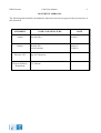
DOCUMENT APPROVAL
The following table identifies all authorities who have successively approved the present issue of
this document.
AUTHORITY
NAME AND SIGNATURE
DATE
Author
Bert Sauviller
19/04/07
Editors
Tom De Wit
Jeroen Janssens
18/01/07
11/08/10
Director ATC
Director Software
Department
Ing. M. Vanuytven
Ir. E. Moons
PSR Extractor
CAM User Manual
-4-
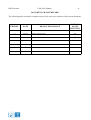
DOCUMENT CHANGE RECORD
The following table records the complete history of the successive editions of the present document.
REASON FOR CHANGE
SECTIONS
PAGES
AFFECTED
EDITION
DATE
1.0
18/04/07
New document
All
1.1
20/04/07
Editing, add some info
All
1.3
02/10/07
Updated to CAM version 1.2.0.
All
1.4
24/10/07
Updated to CAM version 1.3.0
All
1.5
18/01/08
CAM version 1.3.0 completion of manual
All
1.6
05/02/08
Minor changes, extra explanation
All
1.7
08/11/10
Updated to CAM version 1.3.3
All
PSR Extractor
CAM User Manual
-5-
TABLE OF CONTENTS
1. INTRODUCTION........................................................................................................................................................10
2. RASS-R TOOLBOX....................................................................................................................................................12
3. DIFFERENT MODULES........................................................................................................................................... 14
3.1 HARDWARE/SOFTWARE OVERVIEW.................................................................................................................................. 14
3.2 USER INTERFACES OVERVIEW......................................................................................................................................... 16
4. PSR EXTRACTOR CAM...........................................................................................................................................17
4.1 FILE MENU..................................................................................................................................................................18
4.1.1 View EventLog................................................................................................................................................ 18
4.1.2 File recorder................................................................................................................................................... 19
4.1.3 System Load Display.......................................................................................................................................19
4.1.3.1 Reply combiner – buffer fill level...............................................................................................................................
4.1.3.2 Reply combiner – Reply load......................................................................................................................................
4.1.3.3 Reply combiner – Time load.......................................................................................................................................
4.1.3.4 Combiner - #combines/sec..........................................................................................................................................
4.1.3.5 Combiner - #PSR messages/sec – received................................................................................................................
4.1.3.6 Combiner - #PSR messages/sec – used.......................................................................................................................
4.1.3.7 Combiner - #SSR messages/sec – received................................................................................................................
4.1.3.8 Combiner - #SSR messages/sec – used.......................................................................................................................
4.1.3.9 Combiner – working queue size..................................................................................................................................
4.1.3.10 Combiner – combining percentage...........................................................................................................................
4.1.3.11 Combiner – loop time [ms].......................................................................................................................................
4.1.3.12 Combiner – processing delay [ms]............................................................................................................................
4.1.3.13 Tracker - # active tracks............................................................................................................................................
4.1.3.14 Tracker – input buffer size........................................................................................................................................
4.1.3.15 Tracker – processing delay [ms]...............................................................................................................................
4.1.3.16 Tracker – processing time [ms].................................................................................................................................
4.1.3.17 CPU load [%]............................................................................................................................................................
4.1.3.18 Used memory [Mbyte]..............................................................................................................................................
20
20
20
20
20
20
21
21
21
21
21
21
21
21
21
22
22
22
4.1.4 Probe Settings................................................................................................................................................. 22
4.1.5 STC Fixed attenuation settings....................................................................................................................... 22
4.1.6 Advanced settings editor.................................................................................................................................23
4.1.7 Map Editor...................................................................................................................................................... 24
4.1.8 PCT Flash Programmer................................................................................................................................. 26
4.1.9 PCT Flash Editor............................................................................................................................................26
4.1.10 About.............................................................................................................................................................28
4.2 MAIN TOOLBAR........................................................................................................................................................... 29
4.2.1 Manual offset compensation........................................................................................................................... 29
4.2.2 Clutter Map.....................................................................................................................................................30
4.2.3 PCT ini-file..................................................................................................................................................... 30
4.3 DIFFERENT TABS..........................................................................................................................................................31
4.3.1 Main tab..........................................................................................................................................................31
4.3.2 PCT tab........................................................................................................................................................... 32
4.3.3 CAM info tab...................................................................................................................................................34
4.3.4 Extractor tab................................................................................................................................................... 35
4.3.5 Tracker/Combiner...........................................................................................................................................37
4.3.6 Connection info tab.........................................................................................................................................38
4.3.7 Server Manager tab........................................................................................................................................ 39
4.3.8 I/Q view tab.....................................................................................................................................................40
4.3.9 Error tab......................................................................................................................................................... 41
5. TROUBLESHOOTING.............................................................................................................................................. 42
5.1 NETWORK TESTING.......................................................................................................................................................42
PSR Extractor
CAM User Manual
-6-
5.2 PROBLEMS WITH CONNECTION TO EXTRACTOR OR TRACKER/COMBINER SERVER ....................................................................43
5.3 HOW TO CHECK IF A WINDOWS SERVICE IS RUNNING?....................................................................................................... 44
5.4 HOW TO RESTART A WINDOWS SERVICE.......................................................................................................................... 45
6. APPENDIX: HOW-TO-DO........................................................................................................................................46
6.1 HOW TO SELECT A FILE ON AN OTHER COMPUTER.............................................................................................................. 46
6.2 OPEN A REMOTE DESKTOP CONNECTION...........................................................................................................................47
PSR Extractor
CAM User Manual
-7-
TABLE OF FIGURES
FIGURE 1-1: PRE790..................................................................................................................................................... 11
FIGURE 1-2: PCT791..................................................................................................................................................... 11
FIGURE 1-3:PROCESSING SERVER......................................................................................................................... 12
FIGURE 2-4: RASS-R TOOLBOX................................................................................................................................13
FIGURE 2-5: CAMPAIGN DIRECTORY STRUCTURE.......................................................................................... 14
FIGURE 3-6: EXAMPLE OF HARDWARE CONFIGURATION............................................................................17
FIGURE 3-7: USER INTERFACES OVERVIEW.......................................................................................................18
FIGURE 4-8: CAM USER INTERFACE......................................................................................................................19
FIGURE 4-9: INFO/WARNING/ERROR VIEWER................................................................................................... 20
FIGURE 4-10: RECORDER WINDOW....................................................................................................................... 21
FIGURE 4-11: SYSTEM LOAD DISPLAY..................................................................................................................21
FIGURE 4-12 SYSTEM LOAD DISPLAY - FIELDS..................................................................................................22
FIGURE 4-13: PROBE SETTING EDITOR................................................................................................................ 24
FIGURE 4-14: ADVANCED SETTINGS EDITOR – TRACKER............................................................................. 25
FIGURE 4-15: MAP EDITOR - THRESHOLD MAP.................................................................................................26
FIGURE 4-16: MAP EDITOR – POWER THRESHOLD MAP................................................................................27
FIGURE 4-17: PCT FLASH PROGRAMMER............................................................................................................28
FIGURE 4-18: PCT FLASH EDITOR – BEAM SWITCHING TABLE...................................................................28
FIGURE 4-19: SELECT PCT FLASH FILE................................................................................................................ 29
FIGURE 4-20: PCT FLASH EDITOR – STC TABLE................................................................................................ 29
FIGURE 4-21: ABOUT PSR EXTRACTOR................................................................................................................ 30
FIGURE 4-22: EVENT VIEWER.................................................................................................................................. 30
FIGURE 4-23: MAIN TOOLBAR................................................................................................................................. 31
FIGURE 4-24: CLUTTER MAP.................................................................................................................................... 32
FIGURE 4-25: PCT INI FILE........................................................................................................................................ 32
FIGURE 4-26: MAIN TAB............................................................................................................................................. 33
FIGURE 4-27: PCT TAB................................................................................................................................................ 34
FIGURE 4-28: STC FIXED ATTENUATION SETTINGS.........................................................................................35
FIGURE 4-29: CAM INFO TAB................................................................................................................................... 36
FIGURE 4-30: EXTRACTOR TAB CONNECTED RUNNING............................................................................... 37
FIGURE 4-31: START EXTRACTOR..........................................................................................................................38
FIGURE 4-32: REPLAY FILE SELECT...................................................................................................................... 38
FIGURE 4-33: TRACKER/COMBINER TAB CONNECTED RUNNING........................................................... 39
FIGURE 4-34: CONNECTION INFO TAB..................................................................................................................40
FIGURE 4-35: EXAMPLE OF EVENT........................................................................................................................ 40
FIGURE 4-36: SERVER MANAGER TAB..................................................................................................................41
FIGURE 4-37: ABORT DHM SESSIONS.................................................................................................................... 41
FIGURE 4-38: IQ VIEW TAB....................................................................................................................................... 42
FIGURE 4-39: DETAILED IQ VIEW OF A TEST PULSE....................................................................................... 42
FIGURE 4-40: DETAILED IQ VIEW OF A POSSIBLE TARGET.......................................................................... 43
FIGURE 4-41: ERROR TAB..........................................................................................................................................43
FIGURE 5-42: RUN DIALOG........................................................................................................................................44
FIGURE 5-43: PING COMMAND................................................................................................................................ 44
FIGURE 5-44: IPCONFIG COMMAND...................................................................................................................... 44
FIGURE 5-45: COMMUNICATION PROBLEM....................................................................................................... 45
FIGURE 5-46: TASKMANAGER................................................................................................................................. 46
FIGURE 5-47: RUN COMMAND................................................................................................................................. 47
FIGURE 5-48: WINDOWS SERVICES........................................................................................................................47
FIGURE 6-49: RUN SELECT........................................................................................................................................ 48
FIGURE 6-50: RUN DIALOG - REMOTE DISK........................................................................................................48
FIGURE 6-51: LOG ON................................................................................................................................................. 48
FIGURE 6-52: REMOTE DESKTOP CONNECTION DIALOG..............................................................................49
FIGURE 6-53: REMOTE DESKTOP CONNECTION COMPUTER.......................................................................49
FIGURE 6-54: ALLOW REMOTE DESKTOP........................................................................................................... 49
PSR Extractor
CAM User Manual
-8-
TABLE OF TABLES
TABLE 2-1: RASS-R MENU BAR................................................................................................................................ 13
TABLE 4-2: MENU BAR................................................................................................................................................18
TABLE 4-3: MAIN TOOLBAR..................................................................................................................................... 29
ACRONYMS
PSR
SSR
PRE
PCT
MRD
DHM
HDMI
CAM
COTS
ATC
ACPR
ARP
STC
PRF
DRAC
primary radar extractor
secondary radar extractor
primary radar extractor
PSR Controlled Timing Unit
Multi Radar Display (refer to the manual of the MRD)
Data Handler Module (refer to the manual of the DHM)
High Definition Multimedia Interface
Control And Monitoring
Commercial Of-The-Shelf
Air Traffic Control
Azimuth Change Pulse Rate
Azimuth Reset Pulse
Sensitivity Time Control
Pulse Repetition Frequency
Dell Remote Access Controller
PSR Extractor
CAM User Manual
-9-
CONVENTIONS USED IN THIS MANUAL
The following conventions are used in this manual:
Note: This icon to the left of bold italicized text denotes a note, which alerts you to
important information.
Caution: This icon to the left of bold italicized text denotes a caution, which alerts you to
the possibility of data loss or a system crash.
Warning: This icon to the left of bold italicized text denotes a warning, which alerts you
to the possibility of damage to you or your equipment
PSR Extractor
CAM User Manual
- 10 -
1. Introduction
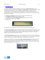
The Primary Radar Extractor or PRE790 is developed to extend the life span of airport
approach primary radar systems and to improve their performance. Although originally developed
for the Thomson TA10M, the system can easily be adapted for usage on other radars (e.g.
Watchman AR51). The main step in the radar upgrade is the replacement of the full receiver
processing unit, resulting in an immediate improvement by use of state of the art radar processing
techniques; for example:
•
•
•
•
•
Synchronous sampling of analog signal providing I and Q digital signals
Full Doppler processing instead of MTI processing
16 bin FFT processing with Adaptive Clutter map for each of the 16 bins
Constant false alarm rate filter (CFAR)
Improved Pd
Figure 1-1: PRE790
The PRE790 has two main units: a video processing unit and a data processing unit.
The video processing unit samples the analog I/Q video (ADC). This digitized video signal is fed
to an internal digital signal processor for further preprocessing and data reduction (filtering). The
video data is aligned with the timing signals (ACP, ARP and trigger) and UTC time stamps are
added by means of Intersoft Electronics’ GPS450.
The data processing unit contains 4 serial ports for input and/or output. It can receive SSR targets
form the existing co-located SSR extractor on its serial input lines. The video and data processing
units are connected over a separate USB-interface to a dedicated processing server.
Additional to the PRE790, a programmable PSR Controlled Timing Unit is installed (PCT791).
This unit typically converts the timing signal outputs of the radar into PRE790 acceptable levels.
Because the timing signals of the radar are manufacturer dependent, this interface unit needs to be
designed specifically for every radar type.
Figure 1-2: PCT791
PSR Extractor
CAM User Manual
- 11 -
The PRE790 is completely controlled by the following software modules (installed on the
processing server):
•
•
•
Extractor function: Doppler processing and PSR plot extraction on the digitized video data.
Combiner/Tracker function: combining the extracted PSR plots with the SSR target data and
making tracks.
RASS-R Data Handling Module software (DHM): possibility to output the different data on
LAN or on serial lines using the data processing unit in the PRE790. Also, the DHM can send
the video data over LAN to ATC centres or other clients.
The processing computer is a 19inch rack server with no screen nor keyboard attached. It can be
accessed using Windows Remote Desktop from the management console. Starting up/shutting
down can be remote controlled using the web application of the Remote Access Controller (DRAC)
interface.
Figure 1-3:processing server
The Control And Monitoring (CAM) software, serves as Human Machine Interface and controls the
PRE790. The software runs on a remote monitoring station that acts as management console. As an
asset, Intersoft Electronics' Multi Radar Display 3 or Technical Maintenance Display 3 can be
installed on the management console, displaying the plot and video data in PPI style.
This manual explains the use of the Control And Monitoring software, or ‘PSR Extractor CAM’.
For detailed explanation about the extractor and the complete software and hardware design, we
refer to the technical manual “IE-PSR-Extractor-TM-vxx.pdf”.
Other names used for the management console are: management pc/station, monitor
pc/station.
PSR Extractor
CAM User Manual
- 12 -
2. RASS-R toolbox
The PSR Extractor setup makes use of the Data Handling Module software and the Multi
Radar Display, which are both part of the RASS-R toolbox.
The RASS-R toolbox is installed on your pc and has a shortcut on the desktop. It can also be
accessed using the Windows Start-menu. The toolbox is displayed in Figure 2-4: RASS-R toolbox.
The current version of the RASS-R toolbox is displayed in the right upper corner. The DHM and
MRD3 are part of this RASS-R toolbox and can be opened using the appropriate icons
and
.
On the other hand, also the PSR Extractor CAM has direct shortcuts to these software modules (see
4.2 Main toolbar)
Figure 2-4: RASS-R toolbox
For details about the DHM and MRD3 software we refer to their respective user manuals
“IE-UM-00025-0xx DHM.pdf ” and “IE-UM-00027-0xx MRD3.pdf “.
PSR Extractor
CAM User Manual
- 13 -
The menu bar contains the following items:
Table 2-1: RASS-R menu bar
Button
Help window
Usage
When this button is clicked, the Help window will appear and show help
information whenever you point over a button.
Campaign change
Click this to make an appropriate campaign structure (see further)
Change settings
Under development
Site file
Under development
Print graphs
Under development
Print tables
Under development
Quit the application
Exit
When you click the
button, it will ask you where you want to create your RASS-R campaign
folder. Select the correct path. Upon completion, you should have the following directory structure
created as in Figure 2-5: Campaign directory structure.
Figure 2-5: Campaign directory structure
When you make a campaign folder with the RASS-R toolbox, it is suggested to create it on
a separate drive rather than the drive where your operation system is on. For example, as
in the figure above, a structure named “CAMPAIGN-RASS-R” is created on the D-drive.
PSR Extractor
CAM User Manual
- 14 -
3. Different modules
This chapter gives an overview of the hardware and software (in block diagram and user interfaces).
It will help the reader to better understand the ‘Control And Monitor’ software which is explained
in the next chapter.
3.1
Hardware/software overview
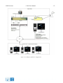
A standard configuration, running different software components, is presented in the figure below.
We can see the following parts:
•
PRE790: installed in a (existing) 19” rack connected with the GPS450, the PCT791 and the
processing server. The PRE790 processes the I/Q video signals coming from the PSR.
•
PSR Controlled Timing Unit: interface for timing signals between the radar and PRE790.
It is connected by a HDMI1-cable. The PCT791 is radar specific!
•
Processing server: the server is connected to the PRE790. It is equipped with sufficient
processing power (CPU), Memory (e.g. 4GB), recording facilities (1TB harddisk, RAID
configuration), DRAC-interface, ... and performs the following tasks:
o Extractor server: Extraction of primary plots using the video data
o Tracker/combiner-server: tracking and combining of PSR and SSR plots
o Data Handling Module:
data acquisition of any common radar format (ASTERIX, Aircat, EV760 etc.)
protocol convert into our proprietary D6 format (required for further processing
with any IE software) and/or convert into common used radar formats
(ASTERIX, RDIF, …)
data recording and/or replay
distribute the data over various networks (LAN, WAN, Serial, …)
•
Monitoring station: the monitoring station is a desktop computer, installed in the radar
shelter. It is used to monitor the processing server and fulfils the following tasks:
o Extractor CAM: user interface to configure the extractor server and the
tracker/combiner server software that are running on the processing server.
o DHM Configuration manager: user interface to configure and control the different
DHM sessions running on the processing server.
o MRD3: visualizes the SSR targets, PSR targets, combined targets, tracks and video.
o The monitoring station can also be used to access the processing server using
Windows Remote Desktop. If the processing server is equipped with a DRACinterface, its functionalities can be accessed by typing in the processing server’s
DRAC IP-address in a browser on the monitoring station.
1
The HDMI cable is only used for its cable specifications. The HDMI standard is not followed at all.
PSR Extractor
CAM User Manual
Figure 3-6: Example of hardware configuration
- 15 -
PSR Extractor
3.2
CAM User Manual
- 16 -
User interfaces overview
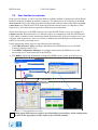
In the previous chapter, we have seen that different software modules communicate with different
hardware modules, installed on multiple computers. The link between all computers is the local
area network (LAN). The different software modules talk with each other using different socketconnections over UDP/IP and TCP/IP (both internal and external between 2 computers). In the
figure below, all coloured arrows represent a different socket connection.
On the processing server, the PSR extractor server and the PSR Tracker server are running as a
windows service. Both functions use 2 different sockets to communicate with the PSR Extractor
CAM, which is installed on the monitoring station. Remember that, if the processing server is not
equipped with a keyboard or screen, you can use Windows Remote Desktop on the monitoring
station to access the processing server.
On the monitoring station, there are the following user interfaces:
• The PSR Extractor CAM to configure and monitor the PSR Extractor server, the PSR
Tracker/Combiner, the PCT791
• The DHM Configuration Manager, to configure and monitor the DHM server on the
processing server, with connection to the PRE790
• The MRD3, displaying information configured in DHM sessions on the processing server.
Radar shelter
Processing pc
DHM running as windows service
2 sockets
LAN connection
Radar shelter
Extractor CAM
Monitoring pc
DHM Configuration manager
MRD
Figure 3-7: User interfaces overview
Setting up the PSR extractor requires good knowledge of networking. All the settings must
be made in the appropriate ini-files (refer to the technical manual).
PSR Extractor
CAM User Manual
- 17 -
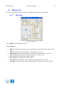
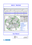
4. PSR Extractor CAM
The PSR Extractor Control And Monitoring user interface runs on the monitoring station. It is
used for remote controlling and monitoring the extractor server and the tracker/combiner server.
It is also used to program and monitor the PCT791.
Directly from this user interface, you can also start/stop the DHM server running on the processing
server, restart the processing server, open the DHM Configuration Manager or the Multi Radar
Display.
File menu
Menu bar
Tabs
Figure 4-8: CAM User Interface
It is very important to remember that the PSR Extractor CAM runs on the monitoring
station.
PSR Extractor
4.1
CAM User Manual
- 18 -
File menu
An overview of all the available menu items is given in Table 4-2.
Table 4-2: Menu bar
Menu
View
View Eventlog
Recorder
System Load
Usage
Opens the Info/Warning/Error Viewer window
Opens the File Recorder Window
Opens the System Load Display Window
Settings
Probe Settings
STC Fixed Att.
Advanced settings
Map editor
PCT Flash
PCT Flash Editor
Opens the Probe Setting Editor
To load the STC settings (only active when the PCT791 is
To load the Advanced settings editor
To load the Map editor
To load the PCT Flash Programmer
To load the PCT Flash Editor
Help
About
Application Summary dialog
The different menu items will be explained in further detail in the next paragraphs.
4.1.1
View EventLog
When you click “View EventLog”, the “Info/Warning/Error Viewer” will be opened.
(Figure 4-9: Info/Warning/Error Viewer)
This list logs all Info, Warnings and Errors events that happen in the software.
You can select whether you want to see the errors, warnings, or info events using the drop down
menu. If you click
, a window will prompt that asks you to save the current information in
a .log-file.
Figure 4-9: Info/Warning/Error Viewer
This information is very useful when troubleshooting your system, since all steps are
logged here.
PSR Extractor
4.1.2
CAM User Manual
- 19 -
File recorder
By clicking “View Recorder” or by pressing
(see 4.1.5), the following window will prompt:
Figure 4-10: Recorder window
If you click to start the recording, the software will record the sampled I/Q video. This data will
be saved in a .2MHz file. The path of this recording is set in the default.ini-file in the Extractor
Server folder. Similar to the recording path, the file size can be set in the default.ini-file (see
technical manual IE-PSR-Extractor-TM-vxx.pdf). When the maximum file size is reached, the
recording automatically stops. Then, a new ‘Start’ is necessary for a next recording.
Note that this recording only records I/Q video before plot extraction. The PSR extracted
plots and/or SSR data can be recorded with the DHM.
Replaying files that you recorded yourself, is not possible in this software version. It is
necessary to synchronize the PSR video and SSR data in a separate software tool that is
not part of this CAM software.
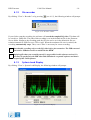
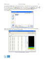
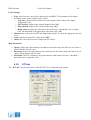
4.1.3
System Load Display
By clicking “View System Load Display, the following window will prompt:
Figure 4-11: System Load Display
PSR Extractor
CAM User Manual
- 20 -
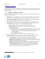
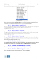
When you click in the upper selection field, the following list of display options appears:
Figure 4-12 System Load Display - fields
When you select an option the last hour history for the selected parameter is displayed. Further
explanation of the meaning of the options will be given in the next paragraphs.
4.1.3.1
Reply combiner – buffer fill level
This item shows the buffer fill level of the reply combiner engine. This buffer stores the reply video
coming from the device for further processing. The fill level is shown in %.
[#replies/buffer size * 100]
4.1.3.2
Reply combiner – Reply load
The reply combiner engine is allowed to processes a maximum number of replies per processing
cycle. This parameter shows the actual used percentage of this maximum.
{#replies/reply limit * 100}.
4.1.3.3
Reply combiner – Time load
The reply combiner engine has a maximum loop time. The loop time is the time needed to do one
processing cycle. This parameter shows how much time is used compared to the maximum loop
time in %. {loop time/max loop time * 100}
4.1.3.4
Combiner - #combines/sec
The combiner combines primary plots with secondary plots. This value shows how much combines
are completed per second (CS). The calculated value is a sliding average over 20 seconds.
4.1.3.5
Combiner - #PSR messages/sec – received
Shows the number of primary messages received, including sector messages.
4.1.3.6
Combiner - #PSR messages/sec – used
Shows the number of primary messages used, sector messages excluded.
PSR Extractor
4.1.3.7
CAM User Manual
- 21 -
Combiner - #SSR messages/sec – received
Shows the number of secondary messages received, including sector messages.
4.1.3.8
Combiner - #SSR messages/sec – used
Shows the number of secondary messages used, sector messages excluded.
4.1.3.9
Combiner – working queue size
When you select this field you can see the number of plots in memory where the combiner engine
can work with. If this value is too small, the combiner has not much possibilities of combining. If
this value is too large it takes more time to compare all probabilities.
4.1.3.10 Combiner – combining percentage
The combining percentage (CB) gives an indication of how much matches there are made between
PSR and SSR plots. In an ideal situation there is for each primary plot a matching secondary plot,
so the combining percentage will be 100% in that situation. An example:
#PSR messages/sec–used = 30
# SSR messages/sec–used = 20
#combines/sec = 17
=> CB= 17 / [(30+20)/2] *100 = 68%
So the combining percentage is calculated by summing the number of primary plots and the number
of secondary plots, this sum is divided by 2. Then divide the #combines/sec by the previous result.
{CB = CS/[(#PSR+#SSR)/2] * 100}.
4.1.3.11 Combiner – loop time [ms]
Shows the loop time of the combiner engine in ms.
4.1.3.12 Combiner – processing delay [ms]
Shows the processing delay of the combiner engine in ms. The processing delay is needed to give
the system time to receive the incoming PSR and SSR data. This delay is also used to compensate
for different delays in the both PSR and SSR systems.
4.1.3.13 Tracker - # active tracks
Shows how much tracks are active in the tracker engine.
4.1.3.14 Tracker – input buffer size
When you select this field you can see the number of plots in memory where the tracker engine can
work with. If the tracker treads a track he will search in this buffer for the best matching plot for
that track.
4.1.3.15 Tracker – processing delay [ms]
This value shows the processing delay of the tracker engine. This means the delay between the
target detection and when the track update leaves the tracker engine.
PSR Extractor
CAM User Manual
- 22 -
4.1.3.16 Tracker – processing time [ms]
Shows the loop time of the tracker engine in ms.
4.1.3.17 CPU load [%]
Shows the processor load of the processing server.
4.1.3.18 Used memory [Mbyte]
Shows the used physical memory of the processing server.
This information is very useful when troubleshooting your system. This info is stored on
disk of the monitor pc for the last 100 days. You can find these loggings in the following
folder: C:\Program Files\Intersoft Electronics\PSR Extractor\Extractor CAM\logs.
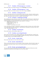
4.1.4
Probe Settings
By clicking “Settings Probe Settings”, you can edit the Gain and Offset applied by selecting that
probe in the “Main tab” of the CAM. The default values are stored in the CAM configuration inifile.
Figure 4-13: Probe Setting Editor
4.1.5
See 4.3.2 PCT tab
STC Fixed attenuation settings
PSR Extractor
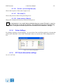
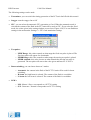
4.1.6
CAM User Manual
- 23 -
Advanced settings editor
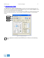
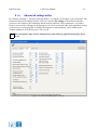
By clicking “Settings Advanced Settings Editor”, a windows as in Figure 4-14 will prompt. The
parameters that can be changed in this screen are used for fine tuning of the different software
processes: the extractor, the combining and the tracker functions. These parameters are loaded
from several .ini-files. Changes to the parameters are not saved and are thus only applicable as long
as the services are not restarted. A detailed description of each parameter can be found in the
Technical Manual “IE-PSR-Extractor-TM-vxx.pdf ”.
These parameters may only be changed by personnel having sufficient knowledge about
its use.
Figure 4-14: Advanced Settings Editor – Tracker
PSR Extractor
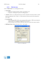
4.1.7
CAM User Manual
- 24 -
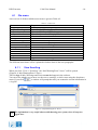
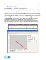
Map Editor
By clicking “Settings Map editor”, the map editor will load.
With this editor you can create or change the Threshold Map and Power Threshold Map. The
maps are stored on the processing server in the folder “c:\Program Files\Intersoft Electronics\PSR
Extractor\Extractor Server\UserPrefs”
A map can be loaded from file with the load button
and saved with the save button
. Each
map is build by connecting a sequence of points. You can run through the points with the next
and previous
button. A point can be removed with the clear button
.
The Threshold Map is variable in range. The threshold is relative and added to the overall
threshold that can be changed in the Main tab of the CAM User Interface (see 4.3.1).
Only video received with a power bigger than the sum of the clutter power and threshold is
applicable to become reply video. We refer to the technical manual for a detailed explanation.
Figure 4-15 shows a Threshold map created by connection following points:
Start Range [Nm]
Start Threshold [dB]
Stop Range [Nm]
Stop Threshold [dB]
0
3
18
3
18
3
55
0
55
50
70
50
Figure 4-15: Map editor - Threshold map
PSR Extractor
CAM User Manual
- 25 -
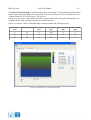
The Power Threshold Map is variable both in range and azimuth. The applied power threshold is
relative and combined with the power threshold as set in the Extractor server user preferences (see
Technical Manual “IE-PSR-Extractor-TM-vxx.pdf ”).
PSR plots with a power, after pathloss and STC compensation, below the power threshold are not
outputted by the reply combiner function of the PSR extractor.
Figure 4-16 shows a Power Threshold Map created by connection following points:
Start Range
[Nm]
Stop Range [Nm]
Start Azimuth
[deg]
Stop Azimuth
[deg]
Start Threshold
[dB]
Stop Threshold
[dB]
0
18
0
360
-5
-5
18
22
0
360
-5
0
22
55
0
360
0
5
Figure 4-16: Map editor – Power Threshold map
PSR Extractor
4.1.8
CAM User Manual
- 26 -
PCT Flash Programmer
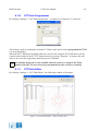
By clicking “Settings PCT Flash Programmer”, a windows as in Figure 4-17 will load.
Figure 4-17: PCT Flash programmer
This dialog is used in combination with the PCT flash editor and is used to program the PCT791
(see next paragraph).
When the STC- and Beam Switching-tables are saved to file using the PCT flash editor, the file
content can be loaded to the PCT791 flash memory by pressing “Program”. A progress bar will
start, do not close the programmer until the process is finished.
Note that this menu item is only available when the extractor is stopped. The Flash
content of the PCT791 unit can not be programmed when the extractor is running.
4.1.9
PCT Flash Editor
By clicking “Settings PCT Flash Editor”, the following window will prompt:
Figure 4-18: PCT Flash Editor – Beam switching table
PSR Extractor
CAM User Manual
- 27 -
In the beam switching table , you can fill in the beam switch table that can be loaded into the
PCT791 flash memory. Click
to load a correct flash file, click
to save and
to erase the current table contents. The flash files are stored on the processing server at the
following location: C:\Program Files\Intersoft Electronics\PSR Extractor\Extractor
Server\FlashContent
Figure 4-19: Select PCT flash file
When you click the STC map, the following window will open. Similar to the Beam switching
table, you can load a file or manually fill in the table.
Figure 4-20: PCT Flash Editor – STC table
PSR Extractor
4.1.10
CAM User Manual
- 28 -
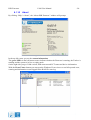
About
By clicking “Help About”, the “About PSR Extractor” window will prompt:
Figure 4-21: About PSR Extractor
In the top left corner you see the contact information.
The green LED's in the left bottom corner indicate whether the Extractor is running, the Tracker is
running and the system is in live or replay mode.
On the right side you get CAM version, PSR extractor and PCT status and device information.
With the Event Viewer button you can open the Windows Event viewer to read all reported error,
warning and information events logged in the RASS-R event log.
Figure 4-22: Event Viewer
PSR Extractor
4.2
CAM User Manual
- 29 -
Main toolbar
The main toolbar is displayed in the following figure:
Figure 4-23: Main toolbar
Table 4-3 is an overview of the buttons of main toolbar.
Table 4-3: Main toolbar
Button
Recording display
Usage
Open the Recording Display. This does the same as choosing “View
Recorder” in the Menu bar.
Triggers manual offset compensation
Save clutter map
Opens the IQ tab (see 4.3.8 I/Q view tab)
Load PCT791 Time Settings
MRD3
DHM
Exit
4.2.1
Launch the MRD3 (Refer to the manual about the Multi Radar Display)
The MRD3 can also be launched in the RASS-R toolbox.
Launch the DHM configuration manager (Refer to the manual about the Data
Handler Module)
The DHM can also be lauched in the RASS-R toolbox.
Quit the application
Manual offset compensation
When you click the manual offset compensation button the system will search for a minimal video
offset setting for both I and Q channel. Should you notice a video offset by using the IQ view you
can use this button to minimize this offset. Offset compensation is automatically executed by every
start of the extractor.
PSR Extractor
4.2.2
CAM User Manual
- 30 -
Clutter Map
When you click the “save clutter map button”
, the following dialog will open:
Figure 4-24: Clutter Map
A clutter map contains the static objects seen by a radar: for example mountain reflections,
obstacles or other not moving parts. On the other hand, also dynamic objects like weather can be
stored in the clutter map. This means that the clutter map is continuously changing while the
Extractor is running.
The clutter map file is split up in 16 clutter maps, one for each Doppler bin. The size of one map is
1024x1024 cells. Each cell contains an 8 byte value.
With this window, you can give the current clutter map a name and save it to file. It will be saved in
the folder C:\Program Files\Intersoft Electronics\PSR Extractor\Extractor Server\ClutterMaps.
(.clmp-file)
When the name already exists, it will overwrite the old map.
4.2.3
PCT ini-file
When you click the “PCT791 button”
, the following dialog will open:
Figure 4-25: PCT INI file
This window is used to load the time settings into the PCT791 unit. Therefore, it is only enabled in
live mode. The directory with the PCT791 ini-files is: C:\Program Files\Intersoft Electronics\PSR
Extractor\Extractor Server\TimingPrefs on the processing server. For detailed description of this
ini-file, consult the Technical Manual.
PSR Extractor
4.3
CAM User Manual
- 31 -
Different tabs
In the next paragraphs, the different tabs of the PSR Extractor CAM are explained.
4.3.1
Main tab
Figure 4-26: Main tab
The “Main tab” has the following items:
General window
•
•
•
•
•
•
•
•
IPR: Interrogations Per Rotation. This value depends on the PRF and the radar rotation
time.
ACPR: Azimuth Change Pulse Rate, i.e. 4096 pulses per cycle
PPS Count: Pulses Per Second (GPS seconds counter when GPS450 connected)
ARP: Azimuth Reset Pulse, increments during live or replay mode
Deg: displays the bearing of the radar in degrees
Sec: displays the revolution time of the radar
GPS Time:the GPS450 time will be displayed here (format: time of week)
Int Time: [UTC] time at the moment of interrogation. (format: time of day [TOD])
PSR Extractor
CAM User Manual
- 32 -
Probe Settings
•
•
•
•
Type: select how the video will be displayed to the MRD3. The parameters will change
according to the “probe settings editor” values.
o Log video: represents the result of the next formula of the I and Q video signal:
20.log(sqrt(I²+Q²))
o FFT channel: output of the selected Doppler filter. [dB]
o Map channel: output of the selected clutter map. [dB]
o Reply Video: displays the video above the clutter map + threshold for all 16 output
bins. The amplitude is the signal above the clutter map. [dB]
Channel: this is only used on FFT and Map Channel probe. It selects the appropriate bin out
of 16.
Gain: controls the gain of the video on the MRD
Offset: this value can be used to compensate DC offsets.
Map Parameters:
•
•
•
Upstep: defines the value that has to be added to the clutter map cell if the new cell value is
greater than the old cell value
Downstep: defines the value that has to be substracted to the clutter map cell if the new cell
value is lower than the old cell value
Threshold: The FFT result has to be greater than the clutter map cell value + threshold +
threshold map to output the result.
4.3.2
PCT tab
The “PCT tab” only becomes active when the PCT791 is connected to the system.
Figure 4-27: PCT tab
PSR Extractor
CAM User Manual
- 33 -
The following settings can be made:
•
Transmitter: you can switch the timing generation of the PCT unit On/Off with this control.
•
Stagger: turn the stagger On or Off
•
STC: you can select the automatic STC generation or fixed. When the automatic mode is
selected the content of the flash in the PCT unit will be used as STC. If you select the fixed
mode, the values given in the setting window are used (see Figure 4-28). You can find these
settings in the menu under Settings STC fixed attenuation settings
Figure 4-28: STC fixed attenuation settings
•
Test pulses:
o PERF Range: this value controls at what range the fixed test pulse is placed. The
fixed test pulse will appear for al azimuths.
o PEMR Range: this value controls at what range the moving test pulse is placed.
o PEMR Azimuth: this value chooses at what azimuth the moving test pulse is
generated. The test pulse will start at the value given and lasts for 15 ACP’s.
•
Beam switching: you can choose between 3 modes
o Automatic: the content in the flash of the PCT791 unit will be used for beam
switching.
o H-beam: the high beam is selected. The content of the flash is overridden.
o L-beam: the low beam is selected. The content of the flash is overridden.
•
LED’s:
o M/S: Master / Slave: corresponds to a PCT791 setting
o G/N: Generator / Normal: corresponds to a PCT791 setting
PSR Extractor
4.3.3
CAM User Manual
- 34 -
CAM info tab
In the “CAM info tab” we can distinguish 4 sections:
•
General Info:
o Engine state: displays when the engine is operational or not
o Loop time: CAM engine loop time, for debug purposes
•
Autostart: if there’s no CAM connection, the extractor and tracker will auto start after a certain
time (in configuration files). If there is a CAM connection this auto start decision depends on
this setting.
•
Event Filter List:
o Sector Messages UDP: if ON, sector messages will be send over UDP (in track and plot
output streams). It is strongly recommend to leave this ON.
o Sector messages CAM: if ON, the PPI on the main tab will follow the antenna rotation.
•
SubEngine Status: displays the status of the .vi sub-engines
Figure 4-29: CAM info tab
PSR Extractor
4.3.4
CAM User Manual
- 35 -
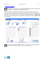
Extractor tab
The “Extractor tab” shows the information about the extractor modules running on the processing
server. The Extractor itself is running in the background on the processing server as a Windows
service. By clicking
or
, you actually start or stop the Extractor
service. The meaning of the LED’s is as follows:
•
•
•
•
Live?: green if live mode is selected
Extractor Error: if there is an error, it will be displayed in the text bar below or in the
“Error tab”.
Extractor running: if the VI’s are loaded and the Extractor is running. (By clicking Start or
Stop) In the right figure below, the CAM is connected and the Extractor is running.
CAM connection: if the connection with the Extractor is made, but not started yet. (the
VI’s are not running – yellow color) In the left figure below, the CAM is connected to the
Extractor but the Extractor is not running.
Figure 4-30: Extractor tab Connected
Running
The PCT.vi is only running when programming the PCT791 flash memory.
The EDR_Replay.vi is only running when the extractor is in replay mode.
PSR Extractor
CAM User Manual
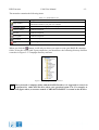
When you click
, it will prompt the following window:
- 36 -
Figure 4-31: Start Extractor
The following settings can be made:
•
•
•
•
Clutter map: select which clutter map must be used. This can be overruled by clicking the
button in “force rebuild clutter map”.
PCT file: select the PCT file to be used
Live mode: the Extractor then works on real live data.
Replay mode: the Extractor works on data that is recorded on disk. When this option is
chosen, Figure 4-32: Replay File Select prompts. You can choose between the available
recordings made. Also some comment will be shown.
Figure 4-32: Replay File Select
PSR Extractor
4.3.5
CAM User Manual
- 37 -
Tracker/Combiner
The “Tracker/Combiner tab” shows the information about the Tracker/Combiner that is running
on the processing server. The Tracker/Combiner itself is running in the background on the
processing server as a Windows service. By clicking
or
, you
actually start or stop the Tracker/Combiner service. The meaning of the LED’s are as follows:
•
•
•
Tracker Error: if there is an error, it will be displayed in the text bar below or in the “Error
tab”.
Tracker running: if the VI’s are loaded and the Tracker/Combiner is running. (By clicking
Start or Stop) In the right figure below, the CAM is connected and the Tracker/Combiner is
running.
CAM connection: if the connection with the Tracker/Combiner is made, but not started yet.
(the VI’s are not running – yellow color) In the left figure below, the CAM is connected to
the Tracker/Combiner but the Tracker/Combiner is not running.
Figure 4-33: Tracker/Combiner tab Connected
Running
PSR Extractor
4.3.6
CAM User Manual
- 38 -
Connection info tab
The “Connection Info Tab” shows info about the Extractor and the Tracker/Combiner.
As you can see in Figure 4-34, the CAM has 2 socket connections per module. If those socket
connections are established between the CAM and the Extractor or Tracker/Combiner module on
the processing server, the status will be “connected”. If the socket connection is not established, the
status will be “Initiating”. (Those socket connections are graphically represented in Figure 3-7: User
interfaces overview)
The LED’s show what kind of information is sent between the CAM and the modules:
•
•
•
Command: in case a command or inquiry is sent (client initiated).
Reply: in case a reply is received.
Event: in case an event occurs (Server initiated). The explanation of the event may appear
in the text field below. (Figure 4-35)
Figure 4-34: Connection Info tab
Figure 4-35: Example of event
PSR Extractor
4.3.7
CAM User Manual
- 39 -
Server Manager tab
The “Server Manager Tab” has the following functions:
•
•
•
DHM-service: You can Start or Stop the DHM server that is running as a Windows service on
the processing server. You see also the current status, in the figure below this is ‘running’.
Restart server: if you want for some reason to restart the complete processing server without
accessing it, you can use this button to do a remote restart. (A complete restart, together with
other functions can also be performed with the DRAC web-interface when applicable.)
DHM process: You can see which DHM sessions are running on the DHM on the processing
server. If you also connect to the DHM server by clicking
you can choose the
, the sessions become active and
button. (see figure Figure 4-37)
Figure 4-36: Server Manager tab
The info in the text field is also saved in the “Info/Warning/Error Viewer”, section “Info”.
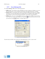
Figure 4-37: Abort DHM sessions
PSR Extractor
4.3.8
CAM User Manual
- 40 -
I/Q view tab
When you click the
button and open the “IQ view tab”, a snapshot of that moment from the
raw IQ video will be taken and displayed. The graph will display all video data that was received at
that moment. Closer to the radar (a few µsec on the X-axis), the amplitude will be higher than
further away from the radar. The white graph is the I-signal, the red is the Q-signal.
Figure 4-38: IQ view tab
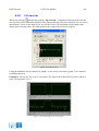
Using the standard Labview buttons for graphs, we can easily zoom on the graph. Two examples
are displayed below.
Example 1: You see the I/Q view of a test pulse. The figure below show the log-video of the test
pulse. (20.log(sqrt(I²+Q²)) )
Figure 4-39: Detailed IQ view of a test pulse
PSR Extractor
CAM User Manual
- 41 -
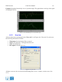
Example 2: displays first the IQ view of a possible target. The graph below is the log-video signal.
(20.log(sqrt(I²+Q²)) )
Figure 4-40: Detailed IQ view of a possible target
4.3.9
Error tab
All errors that occur are displayed in the “Error tab” as in Figure 4-41: Error tab. For each error,
the following information is shown:
•
•
•
•
Timestamp: the time that the Error occurred.
Source: the particular .vi that generates the error.
Code: for internal use
Description: describes the error
Figure 4-41: Error tab
All these errors are also saved in the Info/Warning/Error viewer –window, section errors. (See
4.1.1)
PSR Extractor
CAM User Manual
- 42 -
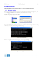
5. Troubleshooting
Next paragraphs gives a few suggestions that can be used to troubleshoot the system.
5.1
Network testing
To test if the monitoring station has a proper network connection with the processing server, you
can use the ping command on the monitoring station. Follow the next steps:
Open the DOS-prompt using the run-window.
Figure 5-42: Run dialog
Suppose that the IP address of the processing server is 192.168.0.92. In the figure below, the ping
command is successful, which means good connectivity.
Figure 5-43: Ping command
To check the ip-address of the local computer, you can type “ipconfig”:
Figure 5-44: Ipconfig command
PSR Extractor
5.2
CAM User Manual
- 43 -
Problems with connection to Extractor or Tracker/Combiner
server
Suppose you see no information at all in the Extractor tab.
Figure 5-45: Communication problem
This means that a socket connection between the PSR Extractor CAM and the Extractor server
cannot be made.
This can be caused by networking problems or wrong settings in the different ini-files (refer to the
technical manual IE-PSR-Extractor-TM-vxx.pdf)
This does not mean that the Extractor server itself is not running! This gives only an
indication about the fact that no communication to the extractor server can be established.
A similar explanation is true for the tracker/combiner server.
PSR Extractor
5.3
CAM User Manual
- 44 -
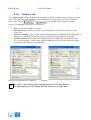
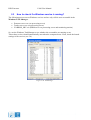
How to check if a Windows service is running?
The following process run as Windows services and are only visible as an executable in the
Windows Task Manager:
•
•
•
Extractor server.exe (on processing server)
Tracker server.exe (on processing server)
YARDIOS_SRV.exe (DHM-server on processing server and monitoring station)
So, use the Windows Task Manager to see whether the executables are running or not.
Those three services should automatically start when the computer boots. If not, check the launch
settings of the services (see 5.4)
Figure 5-46: Taskmanager
PSR Extractor
5.4
CAM User Manual
- 45 -
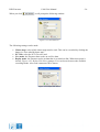
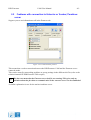
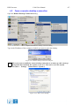
How to restart a Windows service
The Windows Service dialog can easily be started by typing the following run command:
Figure 5-47: Run command
In the services window, you can use the buttons or a right click on the appropriate services for a
start-, stop- or restart-action.
Figure 5-48: Windows services
By right-clicking the services advanced settings such ad Start-up Type can be configured.
PSR Extractor
CAM User Manual
- 46 -
6. Appendix: how-to-do
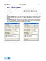
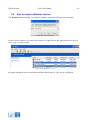
6.1
How to select a file on an other computer
Open the run dialog:
Figure 6-49: Run select
Type in the following text: \\xxx.xxx.xxx.xxx\c$ where the x’s are replaced by the IP number of the
remote computer. In this example the c-drive is selected, to select an other drive replace the c by the
drive letter wanted.
Figure 6-50: Run dialog - remote disk
It can be needed to log on to the remote computer by using a User name and Password
Figure 6-51: Log on
PSR Extractor
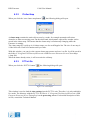
6.2
CAM User Manual
- 47 -
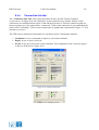
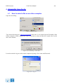
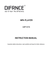
Open a remote desktop connection
Open the Remote Desktop Connection dialog
Figure 6-52: Remote desktop connection dialog
Type in the IP address of the computer of which you want to open the desktop
Figure 6-53: Remote desktop connection computer
When you want to establish a remote desktop connection to a remote pc, this remote pc
must permit that somebody has remote access to it. This can be set in the System
Properties (Start – Settings – Control Panel – System ):
Figure 6-54: Allow remote desktop