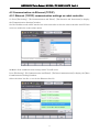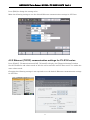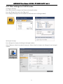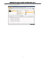
1
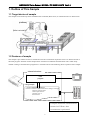
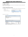
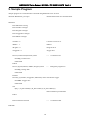
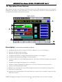
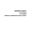
ROBOT Communication Sample Program KEYENCE Vision Sensor MODEL: CV-X100 Series (CV-X100/150/170) Sample Program User’s manual Introduction This document is a user's manual for the sample program to use “KEYENCE Vision Sensor CV-X100 Series” connected to the DENSO robot controller. For details and handling of the connected device, refer to the user’s manual of “KEYENCE Vision Sensor CV-X100 Series”. Caution: (1) This library is designed exclusively for DENSO robot controller RC8 series and cannot be used for other devices. Note that the functions and performance cannot be guaranteed if this product is used without observing instructions in this manual or modified. (2) All products and company names mentioned are trademarks or registered trademarks of their respective holders. ----------------------------------------------------------------------------------------------------------------------------------------- This manual covers the following product KEYENCE CV-X100 Series ----------------------------------------------------------------------------------------------------------------------------------------- Important To ensure proper and safe operation, be sure to read “Safety Precautions Manual” before using the library. Notice to Customers 1. Risks associated with using this product The user of this product shall be responsible for embedding and using the product (software) on a system and any result from using it. Contents Introduction Notice to Customers 1. Outline of This Sample ...................................................................................................................1 2. How to Import..................................................................................................................................2 3. How to Connect ...............................................................................................................................3 4. Communication Settings for Robot Controller and Device Used ..................................................4 5. Sample Program Execution Procedure.........................................................................................11 6. Function.........................................................................................................................................11 7. Static Variable Used in Function..................................................................................................11 8. Function Description.....................................................................................................................12 9. Sample Program ............................................................................................................................16 10. Operation Panel Screen ..............................................................................................................17 KEYENCE Vision Sensor MODEL:CV-X100/150/170 Ver.1.0 1. Outline of This Sample 1.1 Target device of sample This sample can be used only when a DENSO robot controller (RC8 series) is connected to the CV-X100 series. [CV-X100] [Robot controller] 1.2 Features of sample This sample is provided to use the CV-X100/150/170 native commands required to access CV-X100/150/170 in the robot program. Inclusion of this sample allows customers to establish communication with a robot easily without creating a communication program for CV-X100/150/170. The following shows a position of the sample. Internal structure User program Using sample # include "KEYENCE_CVX.pcs" Function ConnectCVX(ByVal lLineNo as Integer) as Integer On Error Goto ErrorProc Comm.Open lLineNo ConnectCVX = -1 Exit Function : Using the dedicated communication format for CV-X100, data transmission is performed. 1 KEYENCE Vision Sensor MODEL:CV-X100/150/170 Ver.1.0 2. How to Import 2.1 What is "import"? Retrieving of the files from this library into the project to use in WINCAPSIII is called "import". Importing files enables using the retrieved program. 2.2 How to import files to project Select [Project] - [Add Existing File...] on WINCAPSIII to import the following files into the project. ・ Main.pns ・ KEYENCE_CVX.pcs ・ KEYENCE_CVX_sample.pcs Program list after import 2 KEYENCE Vision Sensor MODEL:CV-X100/150/170 Ver.1.0 3. How to Connect 3.1 RS-232C connection example A communication cable needs to be connected to establish communication between the CV-X100 series and a robot controller. To connect to the robot controller via RS-232C, use the optional dedicated cable (KEYENCE PN: OP-26486, OP-26487). [CV-X100] [Robot controller] OP-26487 (Cord length 2.5 m) OP-26486 D-sub 9 pin (female) 3.2 Ethernet (TCP/IP) connection example To connect to the robot controller via Ethernet, use the optional dedicated cable (KEYENCE PN: OP-66843) or a crossover LAN cable. Also, when a switching hub/router is used, use the cable suitable for the switching hub/router specifications. [CV-X100] Crossover cable (3 m) OP-66843 3 [Robot controller] KEYENCE Vision Sensor MODEL:CV-X100/150/170 Ver.1.0 4. Communication Settings for Robot Controller and Device Used Use a teach pendant to adjust the communication settings for the device to be used. 4.1 Communication via RS-232C 4.1.1 RS-232 communication settings on robot controller Press [F6 Setting] - [F5 Communication and Token] - [F3 Data Communication] to display the [Data Communication Settings] window. Select the line No.1 for RS-232C and press [Edit] to change the setting value. Make the following settings to use the default RS-232 communication settings for CV-X100. 4 KEYENCE Vision Sensor MODEL:CV-X100/150/170 Ver.1.0 4.1.2 RS-232C communication settings for CV-X100 series Press [Global] - [Communications & I/O] - [RS-232C] to display the [RS-232C (Non-Procedural) Settings] window. Select the desired setting item and change the value so that it agrees with the robot controller setting. Changing the following settings is not required to use the default RS-232 communication settings for CV-X100. 4.1.3 Other settings for CV-X100 series (1) Trigger Settings Press [Set Camera] to display the [Camera Settings] window. Press the [Trigger] tab and select [External]. Press [Trigger Settings] and check [RS-232C] check box for [Trigger Mode]. 5 KEYENCE Vision Sensor MODEL:CV-X100/150/170 Ver.1.0 (2) Output Settings Press [Output] to display the [Output Settings] window. Select [RS-232C (Non-Procedural)] and press [Select Data] to display the [Output Item Settings] window. Set items to output to the robot controller. 6 KEYENCE Vision Sensor MODEL:CV-X100/150/170 Ver.1.0 4.2 Communication via Ethernet (TCP/IP) 4.2.1 Ethernet (TCP/IP) communication settings on robot controller (1) Press [F6 Setting] - [F5 Communication and Token] - [F2 Network and Permission] to display the [Communication Settings] window. Set the IP address and subnet mask of the robot controller so that the robot controller and CV-X100 series are within the same subnet mask. (2) Make client communication settings with CV-100X series. Press [F6 Setting] - [F5 Communication and Token] - [F3 Data Communication] to display the [Data Communication Settings] window. Select the client line No. to use for the Ethernet line No. 7 KEYENCE Vision Sensor MODEL:CV-X100/150/170 Ver.1.0 Press [Edit] to change the setting value. Make the following settings to use the default Ethernet communication settings for CV-X100. 4.2.2 Ethernet (TCP/IP) communication settings for CV-X100 series Press [Global] - [Communications & I/O] - [Network] to display the [Network Settings] window. Set the IP address and subnet mask so that the robot controller and CV-X100 series are within the same subnet mask. Changing the following settings is not required to use the default Ethernet communication settings for CV-X100. 8 KEYENCE Vision Sensor MODEL:CV-X100/150/170 Ver.1.0 4.2.3 Other settings for CV-X100 series (1) Trigger Settings Press [Set Camera] to display the [Camera Settings] window. Press the [Trigger] tab and select [External]. Press [Trigger Settings] and check [Ethernet/IP] check box for [Trigger Mode]. (2) Output Settings Press [Output] to display the [Output Settings] window. Select [Ethernet (Non-Procedural)] and press [Select Data] to display the [Output Item Settings] window. 9 KEYENCE Vision Sensor MODEL:CV-X100/150/170 Ver.1.0 Set items to output to the robot controller. 10 KEYENCE Vision Sensor MODEL:CV-X100/150/170 Ver.1.0 5. Sample Program Execution Procedure (1) Include the function defined program (KEYENCE_CVX.pcs) into the program created by the user. (2) If the function is called, CV-100X receives and executes the command. (3) CV-X100 generates a response and sends it to RC8. (4) The data received by RC8 is stored to the static variable D_dnCvxData(0), sequentially from the received response. (5) The user program processes the next program based on the received data. 6. Function 6.1 Function The functions with the function names shown in the following table are defined in the standard commands of CV-X100 series. Not all the commands of the device are supported. Function name Process Command X_PW Changes the program No. PW X_R0 Switches to the run mode. R0 X_S0 Switches to the setup mode. S0 X_T Trigger input T1 to T4, TA NOTE: There is a limitation on executing each function, depending on conditions of CV-X100 series. For details, refer to the CV-X100 series user's manual. For example, trigger input is accepted only when CV-X100 series is in the run mode. 7. Static Variable Used in Function Static variables used in this program are as follows. 30 variables are declared as Double type. (Change the number in the specification statement to change the size of received data.) Variable declaration Variable name Description static D_dnCvxData(30) Received data static D_dnCvxData(30) as Double Received data (double) NOTE: Static variables can be used in the controller of version 1.3.* or later. 11 KEYENCE Vision Sensor MODEL:CV-X100/150/170 Ver.1.0 8. Function Description X_PW Usage Changes the program No. Syntax X_PW(<Line No.>,<SD No.>,<Program No.>) <Line No.> 1: Universal port, 2 to 3: Reserved 8 to 15: Ethernet client port < SD No.> 1:SD1 ,2:SD2 <Program No.> 0 to 999 Description The program No. of CV-X100 is changed. Example #Include "KEYENCE_CVX.pcs" 'Include the function for communication. Sub Main Dim lLineNo as Integer lLineNo = 8 'Connect as Line No. 8. IF Not (ConnectCVX(lLineNo)) THEN '---- Connection ON PrintDbg "Connect NG" EXIT SUB End IF IF Not(X_PW(lLineNo, 1, 2)) Then 'Switches to Program No.2 of SD1. PrintDBG "Switch NG" EXIT SUB End If DisconnectCVX lLineNo '---- END Sub 12 Connection OFF KEYENCE Vision Sensor MODEL:CV-X100/150/170 Ver.1.0 X_R0 Usage Switches to the run mode. Syntax X_R0(<Line No.>) <Line No.> 1: Universal port, 2 to 3: Reserved 8 to 15: Ethernet client port Description CV-X100 is switched to the run mode. Example #Include "KEYENCE_CVX.pcs" 'Include the function for communication. Sub Main Dim lLineNo as Integer lLineNo = 8 'Connect as Line No. 8. IF Not (ConnectCVX(lLineNo)) THEN '---- Connection ON PrintDbg "Connect NG" EXIT SUB End IF IF Not(X_R0(lLineNo)) Then 'Changes to the “run mode”. PrintDBG "Switch NG" EXIT SUB End If DisconnectCVX lLineNo '---- END Sub 13 Connection OFF KEYENCE Vision Sensor MODEL:CV-X100/150/170 Ver.1.0 X_S0 Usage Switches to the setup mode. Syntax X_S0(<Line No.>) <Line No.> 1: Universal port, 2 to 3: Reserved 8 to 15: Ethernet client port Description CV-X100 is switched to the setup mode. Example #Include "KEYENCE_CVX.pcs" 'Include the function for communication. Sub Main Dim lLineNo as Integer lLineNo = 8 'Connect as Line No. 8. IF Not (ConnectCVX(lLineNo)) THEN '---- Connection ON PrintDbg "Connect NG" EXIT SUB End IF IF Not(X_S0(lLineNo)) Then 'Changes to the “setup mode”. PrintDBG "Switch NG" EXIT SUB End If DisconnectCVX lLineNo '---- END Sub 14 Connection OFF KEYENCE Vision Sensor MODEL:CV-X100/150/170 Ver.1.0 X_T Usage Inputs a trigger. Syntax X_T(<Line No.>,<Trigger No.>,Result data) <Line No.> 1: Universal port, 2 to 3: Reserved 8 to 15: Ethernet client port <Trigger No.> 1 to 4: T1 to T4, -1: TA Result data: Returned as a character string. Description A trigger is inputted. The received data is sequentially stored from D_dnCvxData(0). The maximum number of received data items is 30. Data exceeding the maximum number is not stored. Example #Include "KEYENCE_CVX.pcs" 'Include the function for communication. Sub Main Dim strResults as string Dim lLineNo as Integer lLineNo = 8 'Connect as Line No. 8. IF Not (ConnectCVX(lLineNo)) THEN '---- Connection ON PrintDbg "Connect NG" EXIT SUB End IF IF Not(X_T(lLineNo, 1, strResults)) Then 'Execute T1 trigger. PrintDBG "Trigger NG" EXIT SUB else P[0] = ( D_dnCvData(0), D_dnCvData(1), D_dnCvData(2) ) 'Received data to position data End If DisconnectCVX lLineNo '---- END Sub 15 Connection OFF KEYENCE Vision Sensor MODEL:CV-X100/150/170 Ver.1.0 9. Sample Program 'Sample program of a communication command using KEYENCE CV-X series #Include "KEYENCE_CVX.pcs" 'Include the function for communication. Sub Main Dim strResults as string Dim iLineNo as Integer Dim iProgNo as Integer Dim iTriggerNo as Integer Dim iSDNo as Integer iLineNo = 8 'Connect as Line No. 8. iSDNo = 1 'SDNo. 1 iProgNo = 0 'Program No.0 iTriggerNo = 1 'Trigger No.1 IF Not (ConnectCVX(iLineNo)) Then '---- Connection ON PrintDbg "Connect NG" EXIT SUB End IF IF Not (X_PW(iLineNo, iSDNo, iProgNo)) Then '--- Change the program No. PrintDbg "Change NG" EXIT SUB END IF IF Not(X_T(iLineNo, iTriggerNo, strResults)) Then 'Execute the trigger. PrintDBG "Trigger NG" EXIT SUB else P[0] = ( D_dnCvxData(0), D_dnCvxData(1), D_dnCvxData(2) ) 'Received data to position data End If DisConnectCVX iLineNo '---- END Sub 16 Connection OFF KEYENCE Vision Sensor MODEL:CV-X100/150/170 Ver.1.0 10. Operation Panel Screen This sample provides the following operation panel screen. This operation panel uses functions defined by the sample to check operations, etc. after connecting to the device. See the following as an application example of the operation panel. [Main screen] 1 2 3 4 6 5 8 10 7 9 12 11 Description Each button functions as follows. 1. Configures the Line No. to connect CV-X100 to. Range: 1 to 3, 8 to 15 (integer) 2. Switches CV-X100 to the run mode. 3. Switches CV-X100 to the setup mode. 4. Configures the SD No. to change the program No. Range: 1 to 2 (integer) 5. Configures the program No. Range: 0 to 999 (integer) 6. Sends the SD No. set in (4) and the program No. set in (5) to CV-X100 to change the program settings. 7. Configures the trigger No. Range: 0 to 4, -1 (integer) 8. Sends the trigger command (the trigger No. set in (7)) to CV-X100 and receives data. 9. Displays the communication result. 10. Displays up to 30 items of received data. Displayed data can be switched by using arrows. 11. Clears the received data. 12. Initializes the operation panel. Use this button if a system error is caused by using a line No. that does not exist. NOTE: Changing and triggers can be executed only when CV-X100 series is in the run mode. 17 KEYENCE Vision Sensor MODEL:CV-X100/150/170 Ver.1.0 Revision History DENSO Robot Communication Sample Program User's manual KEYENCE Vision Sensor CV-X100/150/170 Version Ver1.0.0 Date 2013/2/13 Content First edition DENSO WAVE INCORPORATED No part of this manual may be duplicated or reproduced without permission. The contents of this manual are subject to change without notice. Every effort has been made to ensure that the information in this manual is accurate. However, should any unclear point, error or omission be found, please contact us. Please note that we will not be responsible for any effects resulted from the use of this manual regardless of the above clauses. 18