1
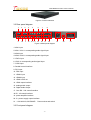
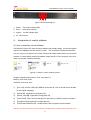
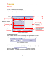
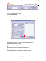
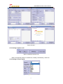
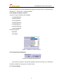
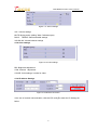
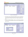
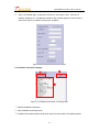
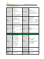
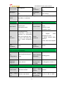
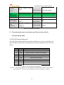
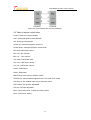
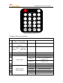
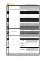
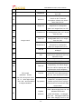
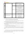
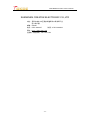
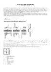
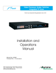
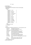
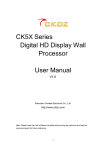
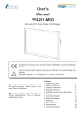
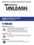
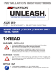
Multi-media matrix switcher
User manual
V1.0
SHENZHEN CREATEK ELECTRONIC CO.,LTD
http://www.ckdz.com/
Attention: Please read this manual carefully before using this product and keep it for future
reference.
CONTENT
CONTENT ................................................................................................................................................ I
1.
SAFETY NOTICE .......................................................................................................................... 1
2.
FUNCTION OVERVIEW ............................................................................................................. 2
3.
HARDWARE STRUCTURE ......................................................................................................... 2
3.1 PRODUCT ELEVATION ..................................................................................................................... 2
3.2 REAR PANEL DIAGRAM .................................................................................................................... 3
3.3 FRONT PANEL DIAGRAM .................................................................................................................. 3
4.
INTRODUCTION OF CONTROL SOFTWARE ....................................................................... 4
4.1 HOW TO INSTALL THE CONTROL SOFTWARE .................................................................................. 4
4.2 HOW TO OPERATE THE CONTROL SOFTWARE ................................................................................ 5
4.2.1 Serial port connection ...................................................................................................... 5
4.2.2 Network Connection ......................................................................................................... 5
4.3 HOW TO OPERATE CONTROL SOFTWARE ....................................................................................... 6
4.3.1 Language selections ......................................................................................................... 6
4.3.2 Menu ...................................................................................................................................... 6
4.3.3 Settings of power on/ff ..................................................................................................... 7
4.3.4 Settings of input signals .................................................................................................. 7
6.3.5 Settings of output resolution .......................................................................................... 8
4.3.6 Analog signal adjustment ................................................................................................ 8
4.3.7 Sound settings ................................................................................................................... 8
4.3.8 Color settings ..................................................................................................................... 9
4.3.9 IP address Settings ........................................................................................................... 9
4.3.10 Status information display ...........................................................................................11
5.
TECHNICAL SPECIFICATION ................................................................................................ 12
6.
COMMUNICATION PORT CONNECTION AND THE REMOTE CONTROL
CORRESPONDING TABLE ............................................................................................................... 14
6.1 RS-232 COMMUNICATION PORT .................................................................................................. 14
6.2 TABLE OF REMOTE CONTROL MENU ............................................................................................. 15
6.3 TABLE OF 9X CONTROL COMMAND ............................................................................................... 16
7.
COMMON TROUBLESHOOTING AND MAINTENANCE ................................................. 19
-i-
CKPS-802Multi-media matrix switcher
1.
Safety Notice
Dangerous
There’s high voltage in processor. To avoid danger, please do not open rear cap without
authorization.
Warning
1、Do not allow liquid, small particles or other objects to get into the device;
2、Do not place the system near fire and water;
3、Do not block any vents. To keep good ventilation, please place the system at least 20
cm away from a wall surface;
4、If any noise、smoke、smell, please cut off the power at once and contact your local
suppliers;
5、Do not connect or disconnect DVI signal cable when the power is on.
Attentions
1、Read the manual carefully before using the system, and keep it for later use;
2、Check the packing list to confirm if there is any missing .If there is , please contact the
local supplier.
3、Cut off the power if thunder or the machine is not used for long term ;
4、You should be well trained before operating the system;
5、Do not slip anything from vent to prevent broken or electric shock;
6、Do not place the device near liquid or moisture;
7、Do not put the device near heat sink or high temperature environment;
8、Keep the power cable properly;
9、If the following situations happen, please cut off the power and for maintenance
1)Liquid splash to device;
2) Device fall down or the cabinet is broken;
3) Any abnormality or malfunction in the system
10、Shenzhen Createk Co., LTD. has the copyright of the manual and reserves the right
of final explanation. Any enterprises or individuals shall not infringe the right without the
agreement of the company. Once found, the company will investigate for relevant legal
responsibility.
-1-
CKPS-802Multi-media matrix switcher
2.
Function Overview
CKPS - 802 is a professional audio/video switching equipment. The device integrates the
leading technology of Createk company for many years on the audio and video image
processing, high-definition signal processing and displaying .It adopts the patent
technology of hardware design. It allows users to switch a variety of audio and video
signals synchronously, and can also to adjust related parameters. It is a high performance
device ,addressed to multimedia conference room ,educational facilities ,command and
control center etc.
CKPS - 802 has the following features:
1、 Hardware-based structure, no CPU and operating system. With core operation
mechanism, it has no trouble of
plug-in processor system's crash ,blue screen and virus
's risk.Start time less than 5 seconds, 365 * 24 hours continuously and stability working.
2、It adopts advanced video image processing chip and algorithm design to realize
HD video and high resolution computer signals' s real-time sampling, transmission and
processing, without delay, trail or frame loss phenomenon. It deals with the image quality
to be good ,smooth.
3、It supports multiple format signals input. 1channel video with audio input, 1channel
YPBPR with audio input, 2 channel VGA signals with audio input, 2 channel HD DP inputs,
2 channel HDMI inputs;
4、 Input resolution up to 1024 x768 ~ 1920 x1200; output resolution up to 640 x480 ~
1920 x1200 ;
5、With the power-off field protection ,input front-end adaptive compensation and
other functions, it supports the input signal condition monitoring and can Real-time
monitor and display the current input channel signal information;
6、 It can adjust the brightness, contrast ratio, saturation, tonal, sharpness, phase of
the output image; and also can adjust the volume, sound of the output audio;
7、With the global general wide voltage design, it can adapt to AC 100 ~ 240 v, 50/60
hz;
8、This product
provides a good man-machine interface for the user. With the
parallel port, Ethernet and RS232 communication interface, and also with the special
matching control software, the series of products can work very well with the computers,
remote control system or other remote control equipment .
3.
Hardware structure
3.1 Product elevation
-2-
CKPS-802Multi-media matrix switcher
Figure 3.1Product elevation
3.2 Rear panel diagram
1
2
3
4
9
10
1
12 13 14 15 16 17 18
19
Figure 3.2Rear panel diagram
5
6
7
8
1.VGA1 input
2.VGA1 VGA1 's corresponding audio signal input
3.VGA2 input
4.VGA2 VGA2 's corresponding audio signal input
5. YPbPr input
6. VGA2 's corresponding audio signal input
7. CVBS input
8. Parallel control interface
9. DP1 input
10. DP2 input
11. HDMI1 input
12. HDMI2 input
13. HDMI LOOP out
14. HDMI output interface
15. analog audio output
16. Digital Audio Output
17. Com RS - 232 control interface
18.RJ - 45 control interface
19. power amplifier interface
20. 5 v power supply output interface
21.(100-240VAC,50HZ/60HZ) Power socket and switch
3.3 Front panel diagram
-3-
20
21
CKPS-802Multi-media matrix switcher
1 2 3 4
Figure 3.3front panel diagram
1、Power: The power indicator light
2、Active:
ormal work indicator
3、Control: Control indicator light
4、IR:
4.
IR Receiver
Introduction of control software
4.1 How to install the control software
CKPS-802 full-color LED video processor adopts user-friendly design. Its control software
requires no installation and the volume is small.
The root folder includes following files,
you can copy it to any place of the control computer and then double-click it to execute file
program. It saves tedious software installation steps and time. Even computer entry-level
users can operate it quickly and easily.
Figure4.1 Folders of control software system
Program operating environment: CPU: more than P4;
Memory: more than 512M;
Hard disk: more than 40G。
1)
【en-US】:sub-file:“CKPS-802-DEBUG.resources.dll”, lack of the file will not be able
to use English language;
2)
【dmdll.dll】:Application configuration file
3)
【dmdll_multi.dll】:Application configuration file
4)
【QLFUI.dll】:This is a mode storage file, and pre-set 16 kinds of mode information.
5)
【System9X.ini】:Application configuration file
6)
【CKPS-802-DEBUG.exe】: Double click the file to operate control software.
Attention: the above six files are all necessary to guarantee the control software operation, and
-4-
CKPS-802Multi-media matrix switcher
they all need to be in the same file .Please do not alter the file, otherwise it will cause software
abnormal use.
4.2 How to operate the control software
Double-click application file“CKPS-802-DEBUG.exe” to open the control software
interface, as shown in the figure below:
Menu
Communication
Status information
Power on/off
Signal source selections
and output settings
Status display
information
Sound settings
Image
Communication settings
Language selections
parameter
Figure 4.2 software interface
4.2.1 Serial port connection
Click【 COM 】in the area of ControlType, then select COM port between the device and
computer. Baud rate should be set to 115200. Click【Connect 】to finish the setting.
Figure 4.3 Serial port connection
4.2.2 Network Connection
Connect the device to LAN and select 【 NET 】in【Control Type】, then click the【Search】
for IP lookup. When
shows the LAN IP of the
device,then click the 【Connect】. See IP address settings in later introductions.
-5-
CKPS-802Multi-media matrix switcher
Figure 4.4 Network Connection
4.3 How to operate control software
4.3.1 Language selections
Select Chinese or English in pull down menu of "Language",the picture below shows the
english software interface.
Figure 4.5 Language selections
4.3.2 Menu
Select a corresponding menu item, and the software interface will change
accordingly.Here is the menu functions:
【BasicSetting】Basic Settings, including Power on/off and audio/video signals settings,
etc.;
【OSD】Menu display, display OSD information of the device;
【Timesetting】Automatic timing switching of the signal windows
【Help】Help information, display version information of the software.
-6-
CKPS-802Multi-media matrix switcher
Figure 4.6 Menu
4.3.3 Settings of power on/ff
Figure 4.7Settings of power on/ff
Select corresponding button to realize boot, standby, boot/standby, restart etc..
4.3.4 Settings of input signals
Figure 4.8 signal sources selection
-7-
CKPS-802Multi-media matrix switcher
There are eight kinds of input signal sources options:2 channel VGA, 2 channel HDMI, 2
channel DP, 1 channel AV, 1 channel YPBPR.
6.3.5 Settings of output resolution
10 kinds of output resolution are available:
1.1920X1080/60Hz
2.1280X720/60Hz
3.1024×768/60Hz
4.1280X1024/60Hz
5.1366X768/60Hz
6.1400X1050/60Hz
7.1600x1200/60Hz
8.1280*768 /60HZ
9.800x600
10.640x480
Figure 4.9 Settings of output resolution
4.3.6 Analog signal adjustment
Figure 4.10 Analog signal adjustment
It can do ADC correction or automatic adjustment (AUTO) for VGA, AV, YPBPR etc.
to solve the problem of wrong color or black border .
4.3.7 Sound settings
-8-
CKPS-802Multi-media matrix switcher
Figure 4.11 Sound settings
VOL: Volume settings
MUTE: Muting switch (ticking" Mute "indicates open)
BASS 、TREBLE: Bass and treble settings
VOLBALAN: Volume balance settings
4.3.8 Color settings
Figure 4.12 Color settings
BRI: Brightness adjustment
CON: Contrast
adjustment
COLOR: Color settings, it works for video.
4.3.9 IP address Settings
Figure 4.13 Network connection
In the use of network communication, click the【IP config】to enter the IP Settings as
below:
-9-
CKPS-802Multi-media matrix switcher
Figure 4.14 IP address Settings
1.
Click【Search】, and the following dialog will display the devices' s IP address (The
user can also reset the device network module first, and then click 【Search】.The
below dialog shows a IP address:192.168.0.250.It is a default IP address after the
reset)
2.
Double-click the【NO】(namely
in figure 6.13 ), and it will pop up a login dialog
box.Enter your user name and password to login (user name and password both are
admin), as below:
Figure 4.15 Login
- 10 -
CKPS-802Multi-media matrix switcher
3.
After a successful login, uncheck the check box "Auto get IP" and fill in the IP
address, gateway etc.. (IP address should be the network segment of the machine
work area, and any unused IP can be set), as below:
Figure 4.16 The interface of IP address input
4.3.10 Status information display
②
①
③
Figure 4.17 Feedback information of working state
① Refresh feedback information
② Clear feedback information area
③ Feedback information display area,which shows current state of the display device.
- 11 -
CKPS-802Multi-media matrix switcher
5.
Technical specification
2 HDMI
2 Display Port
Input signal
1 HDMI
2 VGA
1 compositive video
Output signal
1 YPBPR
1 HDMI LOOP out
Universal I/O connector,2
Output(GPIO, 2out)
Universal I/O connector ,
6input(GPIO, 6 input)
HDMI female
HDMI female
Input
connector
VGA , 15pin female
Display port connector ,
female
BNC female connector
BNC female connector
HDMI female
Universal I/O
Output
connector
connector,
6input,
2output,
( 24V/500mA, 25pin,see
pin chart in user manual)
HDMI 1.3
Input
format
video
RGBHV,
RsGsBs;
Y-Pb-Pr
NTSC
RGBs,
3.58,
RGsB,
NTSC
Output
format
video
HDMI 1.3
RGBHV,
RsGsBs;
RGBs,
RGsB,
4.42,PAL,
SECAM
Video conventional parameters
1080P, 1920*1080;
720P, 1280*720;
1280*768/60HZ
SXGA+, 1400*1050;
Output
resolution
HDMI: 10.2Gbps
SXGA, 1280*1024;
UXGA, 1600*1200;
Video
bandwidth
1366*768
XGA, 1024*768;
DP: 10.8Gbps
composite video: 150MHz
Y-Pb-Pr: 150MHz
VGA: 375MHz
SVGA, 800*600;
VGA: 640*480
Maximum
pixel clock
Switching
speed
165MHz
Switching mode
200ns (maximum.)
Video switching
- 12 -
Quick Switch
Quick Switch
CKPS-802Multi-media matrix switcher
VGA crosstalk
-50dB@5MHz
Signal gain
0dB
Video
impedance
75Ω
Input/output
level
0.5V~2.0Vp-p
Compliant with High-bandwidth Digital Content Protection (HDCP) using DVI
and HDMI 1.3 standards
HDCP
Audio input
Input format
Audio output
1 Stereo master volume
output
7 stereo input
1 Microphone Input
Output format
1 S/PDIF output
1 amplifier output
4 Embedded Audio
1 BNC/RCA
Input
connector
Input
impedance
Audio input
connector for compressed
video and composite video
2 3.5mm VGA audio input
plug 1 6.5mm microphone
jack
1
Captive
connectors, 5 pole
Output
connector
1 S/PDIF Coaxial stereo
interface
1 20*2 watts audio amplifier
Output
impedance
>600Ω
tip(L);ring(R);sleeve(groun
ding)
Stereo Channel
Separation
>80dB @1KHz
20Hz~20K Hz
Common-mode
rejection ratio
>10Ω
screw
Audio conventional parameters
Pin
Configurations
Frequency
Response
>75dB @20Hz to 20K Hz
(CMRR)
Controls parameter
Control mode
Serial
Port
Control
RS232 serial port control,
local area network
Front
Control
Panel
Serial
control
port structure
RS-232, 9-pin female
- 13 -
optional
2 = TX, 3 = RX, 5 = GND
CKPS-802Multi-media matrix switcher
Default
control
Infrared
control
infrared
remote
Network control
Local Area Network
Humidity
5% ~ 95%
Power
Consumption
25W
Product Weight
2.45Kg
Other
specifications
Temperature
-20 ~ +60℃
Power Supply
100VAC
50/60Hz
~
240VAC,
480(W ) x 48(H) x
Case
Dimension
310(D) mm
(1U case)
Table 5.1 Technology parameters
6. Communication port connection and the remote control
corresponding table
6.1 RS-232 Communication port
The CK5 offers standard DB9 RS-232 serial controlling port. It can be controlled by any
other third party control device. RS-232connecror is 9pin female.RS232 pin chart is as
follows:
Pin#
Name
Description
1
NC
--
2
TXD
Signal transmitter, connect to device RXD
3
RXD
Signal receiver, connect to device TXD
4
NC
5
GND
6
NC
--
7
NC
--
8
NC
--
9
NC
--
-Connect to device GND
Table 6.1 RS - 232 port pin configuration
Attention:Please pay attention to TXD and RXD cable sequence when connecting the
processor's RS - 232 port to the computer or central controller. As below:
- 14 -
CKPS-802Multi-media matrix switcher
拼接控制器
Processor
Computer
Figure 6.2 communication line structure's diagram
6.2 Table of remote control menu
Power: Powen on or enter standby
Auto: VGA signal position auto adjustion
Info: showing working staus
Screen up: motorized projector screen up
Screen down: motorized projector screen down
MIC mute: Microphone mute
MIC vol+: MIC volume +
MIC vol-: MIC volumeLine mute: LINE audio mute
Line vol+: LINE audio volume +
Line vol-: LINE audio volumeResol+: Resolution+
Resol-: ResolutionMain Source: main source selection switch
PIP/POP on: switch between signal sourse, PIP mode, POP mode
Sub Source: Sub window input source selection switch
PIP Position: PIP position adjustable
PIP size: PIP size adjustable
Menu: open OSD menu, or back to previous menu
Enter: enter menu setting
- 15 -
CKPS-802Multi-media matrix switcher
Table 6.3 Remote control menu
6.3 table of 9X control command
9X control command
command Format:character
string, case sensitive
Network control:TCP
protocol
Serial port control:baud
rate:115200 data bits:8
stop bit:1
parity check:
no
NO.
Command type
command
Description
1
Power change
Power on/off
2
Power on
Power on. No reaction if the
machine is on.
Power off
Power off. No reaction if the
machine is off.
3
Restart
Restart the machine.
4
R 720P
Set the output resolution to 720P.
5
R 1080P
output resolution 1080P.
R 640*480
output resolution 680*480.
R 800*600
output resolution 800*600.
8
R 1024*768
output resolution 1024*768.
9
R 1366*768
output resolution 1366*768.
Power control
6
7
Setting of output
resolution(60Hz)
- 16 -
CKPS-802Multi-media matrix switcher
10
R 1280*1024
output resolution 1280*1024.
11
R 1400*1050
output resolution 1400*1050.
12
R 1600*1200
output resolution 1600*1200.
13
R 1920*1200
output resolution 1920*1200.
14
AV
main signal source is CVBS
15
YPbPr
main signal source is YPbPr
16
VGA1
main signal source is VGA1
17
VGA2
main signal source is VGA2
18
HDMI1
main signal source is HDMI1
19
HDMI2
main signal source is HDMI2
20
DP1
main signal source is DP1
DP2
main signal source is DP2
PAV
PIP signal source is CVBS
23
PYPbPr
PIP signal source isYPbPr
24
PVGA1
PIP signal source isVGA1
25
PVGA2
PIP signal source is VGA2
26
PHDMI1
PIP signal source isHDMI1
27
PHDMI2
PIP signal source isHDMI2
28
PDP1
PIP signal source isDP1
29
PDP2
PIP signal source isDP2
30
Menu
Recall the menu
31
Left
Go to the left
Right
Go to the right
Up
Go to the upward side
34
Down
Go to the downward side
35
ok
For confirmation
36
Mute
No Volume
37
Vol up
Increase the volume by 1 unit
38
Vol down
Decrease the volume by 1 unit
Vol xxx
“xxx” is a decimal number, ranging
from 0 to 100. To set the volume to
a certain value, like "Vol 10".
40
Bass xx
To set the treble to a certain
value , from 0 to 100.
41
Treble xx
To set the treble to a certain
value , from 0 to 100.
42
Balance xx
To set the sound track balance to
a certain value, from 0-20 ."0"is
the biggest left channel , "10"is the
balanced value and "20"is the
biggest right channel.
36
MMute
Microphone mute
43
MVol up
Increase the microphone volume
21
22
32
33
39
Signal source switching
Menu control
Volume control
- 17 -
CKPS-802Multi-media matrix switcher
by 1 unit
MVol down
Decrease the microphone volume
by 1 unit
MVol xxx
“xxx” is a decimal number, ranging
from 0 to 100. To set the
microphone volume to a certain
value, like "Vol 10".
Bright xxx
To set the main channel
brightness to a designated
value.“xxx” ranges from 0 to 100.
Contrast xxx
To set the main channel contrast
to a designated value.“xxx” ranges
from 0 to 100.
Color xxx
To set the main channel chroma to
a designated value.“xxx” ranges
from 0 to 100.
51
Sharpness xx
To set the main channel
sharpness to a designated
value.“xx” ranges from 0 to 24.
52
ADCCal
ADC Calibration,Only effective to
analogue
53
Auto
Automatic line and field
synchronous adjustment,and only
effective to VGA .
54
Pip on
Open the PIP
55
Pip off
Close the PIP
Pipb xxx
To set PIP
transparency.“xxx”value ranges
from 0 to 100.0 is opacity,and 100
indicates the most transparent .
Pip size
To recall the window size of
preset PIP ,four options:present
size,1/4, 1/2 in the left,full screen.
Pip position
To recall the window positon of
preset PIP ,six options:present
position,top left corner, top right
corner,lower left corner,lower right
corner,center.
PipSize
www,hhh
To set the PIP window size.The
"www" value ranging from 0 to 100
indicates the window
width."0"indicates unchanged
and "100" the biggest width.The
"hhh" value ranging from 0 to 100
44
45
48
49
50
Image control
56
PIP control
(Attention:screen
size:100*100,top left corner
(0,0),down right corner
(100,100),and no relation
to output resolution.
57
- 18 -
CKPS-802Multi-media matrix switcher
indicates window height."0
"indicates unchanged, "100"
the largest height .
58
NTFT
Reset the network module to initial
value: IP address for
192.168.0.250, port for 27011,
baud rate for
9600. Need to set the module
again After reset
Network module reset
59
7.
PipPos xx,yy
To set the central position of the
PIP window."xx"indicates the
horizontal coordinates and the
value ranges from
0-99."yy"indicates the vertical
coordinates and the value ranges
from 1 to 99.When the coordinate
is "0",it means the current
coordinate is unchanged;when the
central positon is contradictory to
the window size,the position will
adjust automatically.
Common troubleshooting and maintenance
1) If the power indicator does not turn bright and the operation has no reaction,
please check whether the power cable input is of fine contact .
2) If the power indicator turn bright, but no image and sound output, please check
whether the device is in standby state. (In standby state, the small light on the right side of
Ethernet port is red)
3) The picture partial color phenomenon or no video signal output, it may be both
ends of signal line joint not to be connected properly.
4)If there is no audio output, please check whether the audio signal in corresponding
signal channel is inputted, whether the volume is set in quiet state, or the speaker opens
or not.
5) Serial port can not control the device,please check whether the communication
port set by control software is the same as device's serial port, or check if the computer
communication port is in good condition.
- 19 -
CKPS-802Multi-media matrix switcher
6) When the network can't control the device, please check whether the device is
connected to the local area network or to find if the device's IP is occupied, The user can
also change the serial control to confirm whether it is the problem of the device itself.
7) If the output image can not display normally, it is possible that input/output device
is without good ground connection.
8) There are obvious static electricity when connect or disconnect connectors.
Possible reasons:ground well.When the user connects or disconnects connectors, there
are obvious static electricity;it is probably caused by wrong ground connection of the
power supply ground wire . please make sure the right ground-connection.Or else,the
wrong operation will damage the machine and shorten the lifespan.
Attentions:
1 The above listed is the common failure in after-sales maintenance. If you find the device
failure phenomena are not in above range. Please notify the suppliers to solve as soon as
possible. Please do not open the case without authorization, so as not to expand the fault or
cause unnecessary safety accidents.
2 Our company reiterates: without the permission, you who take device apart will bear all
the responsibilities that it may bring.
- 20 -
CKPS-802Multi-media matrix switcher
SHENZHEN CREATEK ELECTRONIC CO.,LTD
地址:深圳市宝安 68 区新安街道留仙二路鸿辉工业
园4栋4楼
邮编:518000
电话:0755-26643017
传真:0755-26644342
网站:http://www.ckdz.com
全国统一服务热线:400-039-0399
- 21 -