1
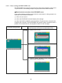
ROBOT
RC7 CONTROLLER
Teach Pendant Panel Editor
Panel Designer
USER'S MANUAL
Copyright © DENSO WAVE INCORPORATED, 2005-2010
All rights reserved. No part of this publication may be reproduced in any form or by any means without
permission in writing from the publisher.
All products and company names mentioned are trademarks or registered trademarks of their respective
holders.
Specifications are subject to change without prior notice.
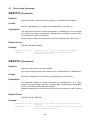
Foreword
This manual sets forth the Panel Designer, a teach pendant panel editor that enables you to create teach
pendant (TP) panel screen software on the computer screen.
This is a supplement to the Setting Manual and WINCAPSIII Guide.
Note for the global type of robot controllers
Version 2.801 or earlier: When the "External auto limited mode" is selected, teach pendant (TP) panel
screen software cannot run in External auto mode. (Refer to the RC7M
Controller Manual.)
Version 2.802 or later: Even in External auto mode, TP panel screen software can run except that RUN
and COTINUERUN commands (TP panel control languages) cannot execute.
Contents
Chapter 1 Panel Designer Overview ............................................................................................................1
1.1 Overview of Procedures for Creating TP Panel Data..........................................................................2
1.2 Editor Screen Functional Description..................................................................................................4
1.2.1 Tool Bars .....................................................................................................................................5
1.2.2 Parts Tree Pane ..........................................................................................................................8
1.2.3 Properties Pane ..........................................................................................................................9
1.2.4 Layout Window............................................................................................................................9
1.2.5 Source Code Edit Window ........................................................................................................10
1.2.6 Compiler Messages Pane .........................................................................................................11
1.2.7 Menus ...................................................................................................................................12
1.3 Creating and Modifying Panel Layouts .............................................................................................14
1.3.1 Adding Parts..............................................................................................................................14
1.3.2 Modifying Panel Layouts ...........................................................................................................14
1.3.3 Changing Part Properties..........................................................................................................15
1.3.4 Deleting Panel Layouts .............................................................................................................15
1.3.5 Importing Panel Layouts from Another TP Panel File ...............................................................15
1.4 Adding Action Source Code ..............................................................................................................16
1.4.1 Writing Action Source Code ......................................................................................................16
1.4.2 Checking (Compiling) Action Source Code...............................................................................16
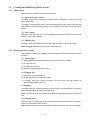
1.5 Miscellaneous....................................................................................................................................17
1.5.1 Property Lists ............................................................................................................................17
1.5.2 Event List ..................................................................................................................................17
1.5.3 Action Source Code Syntax ......................................................................................................18
1.5.4 Sending Data to Controller........................................................................................................18
1.5.5 Important Note on Radio Buttons..............................................................................................18
Chapter 2 Creating TP Panels.....................................................................................................................19
2.1 Configuring Teach Pendant ...............................................................................................................19
2.1.1 Enabling TP Panel Operation....................................................................................................19
2.1.2 Specifying the Start Mode of TP Panel Screen Software [Version 2.32 or later] ......................21
2.1.3 Automatically Displaying TP Panel Screens [Version 2.31 or earlier]......................................23
2.1.4 Specifying the Close Mode of TP Panel Screen Software [Version 2.32 or later].....................24
2.1.5 Hiding the Shortcut Button [Version 2.6 or later].......................................................................25
i
2.2 Using Parts ........................................................................................................................................26
2.2.1 Parts and Their Functions .........................................................................................................26
2.2.2 Specifying Action Source Code for Parts ..................................................................................27
2.2.3 Specifying the RELEASED Event Execution Condition [Version 2.32 or later]........................28
2.2.4 INITIALIZE Event [Version 2.32 or later]..................................................................................31
2.2.5 DONE Event [Version 2.32 or later] .........................................................................................32
2.2.6 Part Descriptions.......................................................................................................................33
2.3 Interfaces with PAC Language and System......................................................................................66
2.3.1 Reading and Displaying PAC Variables ....................................................................................66
2.3.2 Modifying PAC Variables ...........................................................................................................69
2.3.3 Reading I/O States ....................................................................................................................72
2.3.4 Modifying I/O States ..................................................................................................................74
2.3.5 Reading System Status.............................................................................................................76
2.4 Switching TP Panels .........................................................................................................................78
2.4.1 Example Switching in Same Folder ..........................................................................................78
2.4.2 Example Switching Between Folders........................................................................................80
2.5 Flow Control ......................................................................................................................................82
2.5.1 Conditional Branching ...............................................................................................................82
2.5.2 Iteration ...................................................................................................................................84
2.6 Local Variables ..................................................................................................................................85
Chapter 3 TP Panel Control Language's Structural Elements ................................................................87
3.1 Language Elements ..........................................................................................................................87
3.2 Names ...............................................................................................................................................87
3.3 Identifiers and Variables ....................................................................................................................88
3.3.1 Variables ...................................................................................................................................88
3.3.2 Global Variables ........................................................................................................................88
3.3.3 Local Variables ..........................................................................................................................89
3.3.4 Object Properties ......................................................................................................................89
3.3.5 Folder Variables ........................................................................................................................96
3.4 TP Panel Program.............................................................................................................................97
3.5 Data Types ........................................................................................................................................97
3.6 Type Conversion ...............................................................................................................................98
3.7 Constants ..........................................................................................................................................98
3.8 Expressions and Operators...............................................................................................................99
Chapter 4 TP Panel Control Language Syntax .......................................................................................102
4.1 Statements and Lines......................................................................................................................102
4.2 Character Set ..................................................................................................................................102
4.3 Reserved Words..............................................................................................................................102
4.4 Declaration Directives .....................................................................................................................103
4.5 Assignment Statements...................................................................................................................104
4.6 Flow Control Statements .................................................................................................................104
4.7 I/O Control Statements ....................................................................................................................105
4.8 Task Control Statements .................................................................................................................105
4.9 Functions .........................................................................................................................................106
4.10 System Information .........................................................................................................................106
4.11 Preprocessor ...................................................................................................................................106
ii
Chapter 5 Command Reference ...............................................................................................................107
5.1 List of TP Panel Control Commands ...............................................................................................107
5.2 Declaration Statements ...................................................................................................................109
DEFINT (Statement) ..........................................................................................................................109
DEFSNG (Statement)........................................................................................................................109
DEFDBL (Statement)......................................................................................................................... 110
DEFSTR (Statement) ........................................................................................................................ 110
DEFIO (Statement) ............................................................................................................................ 111
5.3 Flow Control Statements ................................................................................................................. 112
FOR…NEXT (Statement) .................................................................................................................. 112
IF…END IF (Statement) .................................................................................................................... 113
SELECT CASE (Statement) .............................................................................................................. 114
5.4 Input/Output Control Statements..................................................................................................... 115
IN (Statement) ................................................................................................................................... 115
OUT (Statement) ............................................................................................................................... 115
SET (Statement) ................................................................................................................................ 116
RESET (Statement) ........................................................................................................................... 116
MSGBOX (Statement) ....................................................................................................................... 117
PAGE_CHANGE (Statement)............................................................................................................ 117
5.5 Multitasking Control Statements...................................................................................................... 118
RUN (Statement) ............................................................................................................................... 118
KILL (Statement)................................................................................................................................ 119
SUSPEND (Statement) ..................................................................................................................... 119
SUSPENDALL (Statement) ...............................................................................................................120
KILLALL (Statement) .........................................................................................................................120
CONTINUERUN (Statement) ............................................................................................................121
DEADMANSTATE (Statement)..........................................................................................................121
5.6 Constants ........................................................................................................................................122
OFF (Built-in constant) ......................................................................................................................122
ON (Built-in constant) ........................................................................................................................122
PI (Built-in constant) ..........................................................................................................................123
FALSE (Built-in constant) ..................................................................................................................123
TRUE (Built-in constant)....................................................................................................................124
5.7 Time/Date Control ...........................................................................................................................125
DATE$ (System Variable)..................................................................................................................125
TIME$ (System Variable) ..................................................................................................................125
TIMER (System Variable) ..................................................................................................................126
5.8 Character String Functions..............................................................................................................127
STR$ (Function) ................................................................................................................................127
CHR$ (Function) ...............................................................................................................................127
SPRINTF$ (Function) ........................................................................................................................128
5.9 System Information .........................................................................................................................129
CUROPTMODE (Statement).............................................................................................................129
SYSSTATE (Statement).....................................................................................................................129
STATUS (Function)............................................................................................................................130
5.10 Preprocessors .................................................................................................................................131
#define (Preprocessor statement) .....................................................................................................131
#include (Preprocessor statement) ...................................................................................................132
iii
iv
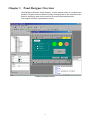
Chapter 1 Panel Designer Overview
WINCAPSIII includes the Panel Designer, a teach pendant editor for creating teach
pendant (TP) panel screen software by simply arranging parts on the computer screen
and then specifying action source code for the events associated with them.
This chapter outlines the procedures involved.
Creating TP Panel Screens
1
1.1
Overview of Procedures for Creating TP Panel Data
The procedure for creating TP panel data consists of the following five basic steps.
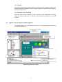
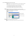
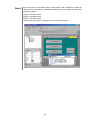
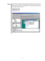
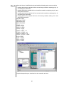
(1) Load editor
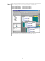
1) In WINCAPSIII, choose Project | Add Program to display the "Create new program"
dialog.
2) In Type, select Operation panel (*.pnl), enter the desired file name, and press OK to
start the Panel Designer.
Note: To open existing TP panel data, double-click it in the Program List.
"Create new program" Dialog in WINCAPSIII
Panel Designer Window for New Panel Layout
2
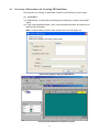
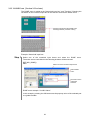
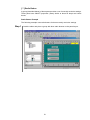
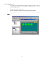
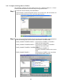
(2) Create panel layout
Select the necessary parts from the Parts tool bar and arrange them in the Layout
window to create the TP panel screen.
For further details, see Chapter 2 "Creating TP Panels."
Parts tool bar
Layout window
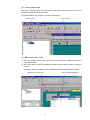
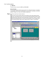
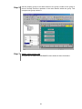
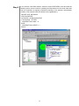
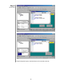
(3) Edit action source code
1) Click the Display source code icon in the Layout window to display the Source
Code Edit window.
2) Add to the Source Code Edit window the action source code for when the part is
pressed.
For further details, see Section 2.2.2 "Specifying Action Source Code for Parts."
Display source code icon
Source Code Edit window
3
(4) Compile
Compile the action source code just written to check for syntax, typing, or other errors.
Progress and other messages from the compiler appear in a pane near the bottom of
the main editor window.
(5) Send data to the controller
Send the newly created TP panel file to the controller, using WINCAPSIII. Note that
using the teach pendant as an operating panel requires reconfiguring the teach
pendant.
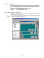
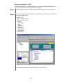
1.2
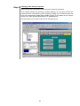
Editor Screen Functional Description
The following figure gives the editor screen layout. The following pages describe the
individual components.
Tool bars
(Section 1.2.1)
Layout window
Parts tree pane
(Section 1.2.4)
(Section 1.2.2)
Source code edit window
(Section 1.2.5)
Properties pane
(Section 1.2.3)
Compiler messages pane
(Section 1.2.6)
Panel Designer Screen Layout
4
1.2.1 Tool Bars
The editor provides the following handy tool bars for creating TP panel data.
(1) Main tool bar
This provides the following buttons.
Name
Description
New
Create a new TP panel file.
Open...
Open an existing TP panel file.
Save
Save the current file to disk, overwriting any older version
there.
Cut
Move the contents of the selected range to the system
clipboard.
Copy
Copy the contents of the selected range to the system
clipboard.
Paste
Insert the clipboard contents at the current cursor position.
Undo
Reverse the effects of the last operation.
Redo
Undo the last undo operation--in other words, repeat the
last operation.
Print
Print the current screen.
About
Display the About screen indicating the editor's version
number, etc.
(2) Zoom grid tool bar
These buttons change the Layout window magnification, toggle the grid display on and
off, etc.
Name
Description
Zoom
Change the magnification ratio for the selected region.
Cancel Zoom
Cancel zooming and return the Layout window to the
standard (100%) magnification.
Pan
Shift the display screen in the specified direction.
Grid
Toggle the grid display on and off.
Snap
Toggle automatic grid positioning on and off.
5
(3) Layout tool bar
These buttons assign uniform positioning, spacing, or size to the selected parts.
Name
Description
Align Top
Align along the upper edge.
Align Middle
Align vertical centers.
Align Bottom
Align along the lower edge.
Align Left
Align along the left edge.
Align Center
Align horizontal centers.
Align Right
Align along the right edge.
Space across
Standardize horizontal spacing.
Space down
Standardize vertical spacing.
Same width
Standardize width.
Same height
Standardize height.
Same size
Standardize size.
(4) Parts tool bar
Most of these buttons select a part to add to the panel layout in the Layout window.
Name
Description
New panel
Create a new panel layout.
Select parts
Select a part pointed with this cursor.
Label
Add part: label.
Text box
Add part: text box.
Numerical
value input
box
Add part: numerical input box.
Group box
Add part: group box.
Radio button
Add part: radio buttons.
Check box
Add part: check box.
Push button
Add part: push button.
Illuminated
push button
Add part: illuminated push button.
Pilot lamp
Add part: pilot lamp.
Line
Add part: line.
Rectangle
Add part: rectangle.
Oval
Add part: oval.
Function key
Add part: function key.
Timer
Add part: timer.
Compile
Translate the corresponding TP panel file into executable
format.
6
(5) Move tool bar
These buttons move parts around the panel layout and within the file's part hierarchy.
Name
Description
Front
Move to the top layer.
Back
Move to the bottom layer.
Forward
Move forward one layer.
Backward
Move backward one layer.
Nudge up
Move up.
Simultaneously holding down the Shift key moves 5 pixels
each time.
Nudge down
Move down.
Nudge left
Move left.
Nudge right
Move right.
7
1.2.2 Parts Tree Pane
This displays the current file's panels and parts in tree format.
(1) Parts Tree pane
The following figure shows a sample Parts Tree pane.
Double-clicking on a part displays its panel layout.
(2) Parts tool bar
This provides the following buttons.
Name
Description
Layout form
Specify the Layout window as target.
Source form
Specify the Source Code Edit window as target.
Layout window
Display the target window specified above.
Erase panel
Delete a panel layout from the TP panel data.
8
1.2.3 Properties Pane
This accesses the position, size, and other properties for a part.
The list of properties depends on the part type. For further details, see Section 1.5.1
"Property Lists."
Properties Pane
1.2.4 Layout Window
This window is for designing teach pendant TP panel screen software by placing parts
on this screen and then adjusting their positions and sizes with the cursor keys or
rubber band drag operations.
Clicking on the Display source code icon displays the corresponding Source Code Edit
window.
Display source code icon
Layout window
(client area)
Layout Window
9
1.2.5 Source Code Edit Window
This window is for assigning action source code to events associated with the parts on
the current panel layout.
(1) Source Code Edit window tool bar
(3) Event list box
(2) Part list box
(4) Action source code block
Source Code Edit Window
(1) Source Code Edit window tool bar
Name
Description
Layout window
Display the corresponding panel layout.
Indent
Shift the selected lines one tab position to the
right.
Outdent
Shift the selected lines one tab position to the
left.
Comment out
Comment out the selected lines.
Undo comment block
Cancel commenting out for the selected lines.
Bookmark
Toggle bookmark on the current source code
line.
Next bookmark
Move the cursor to the next bookmark.
Previous bookmark
Move the cursor to the previous bookmark.
Clear bookmarks
Cancel all bookmark definitions.
Find and replace
Find the specified string and optionally
replace it.
Note: Setting a bookmark on a code line displays a square marker (
10
) to its left.
(2) Part list box
Select the part for which to assign action source code.
(3) Event list box
This lists the events available for the selected part. Selecting one automatically
generates the corresponding skeleton action source code block on the editor screen.
Example: Skeleton action source code block for pressing Button1
DEF Button1_CLICKED()
END
(4) Action source code block
Flesh out the skeleton with action source code.
Example: Action source code block for pressing Button1
DEF Button1_CLICKED()
Set IO[128]
Run PRO100
END
' turn I/O variable #128 ON
' run PRO100
1.2.6 Compiler Messages Pane
This displays progress and other messages from the compiler as it compiles the TP
panel data.
Double-clicking on an error message line displays the corresponding source code in a
Source Code Edit window.
Compiler Messages Pane
11
1.2.7 Menus
This section lists the editor's menus and menu commands.
(1) File
Menu Command
Description
New
Create new TP panel file.
Open…
Open an existing TP panel file.
Close
Close the current file, first displaying the dialog box for
saving if current file edits have not been saved.
Save
Save the current file to disk, displaying the dialog box for
saving if the file is new.
Save As…
Save the current file to disk under a new name.
Print…
Print the contents of the current window: Layout or Source
Code Edit.
Print Preview…
Display a print image on the screen instead of sending
data to the printer.
Printer Setting
Display the dialog box for specifying printer settings.
Import...
Read panel layouts from another TP panel file.
Most recently
used files
This section lists the last few TP panel files saved.
Exit
Close the editor.
(2) Edit
Menu Command
Description
Undo
Reverse the effects of the last operation.
Redo
Undo the last undo operation--in other words, repeat the
last operation.
Cut
Move the contents of the selected range to the system
clipboard.
Copy
Copy the selected parts or string to the system clipboard.
Paste
Insert the clipboard contents at the current cursor position.
Delete
Delete the selected parts or string.
Find
Display the dialog box for finding (and optionally
replacing) the specified string.
(3) View
Menu Command
Description
Tool bar
Toggle display of tool bars.
Status bar
Toggle display of status bar.
Tree bar
(Parts tree)
Toggle display of the Parts Tree pane.
Property bar
(Property)
Toggle display of the Properties pane.
Panel layout
Display the corresponding panel layout.
Grid
Toggle the grid display on and off.
Snap to grid
Toggle automatic grid positioning on and off.
12
Menu Command
Description
Zoom Normal
Cancel zooming and return the Layout window to the
standard (100%) magnification.
Zoom Percent
Change the magnification ratio for the Layout window
(50%, 75%, 100%, 200%).
(4) Tool
Menu Command
Description
Options…
Specify the compiler output version.
Compile
Translate the corresponding TP panel file into executable
format.
(5) Window
Menu Command
Description
Close
Close the currently selected window.
Close all
windows
Close all open editor windows.
Cascade
Display all open windows with the same size and
overlapped with only their title bars visible.
Tile
Display all open windows as individual rectangles dividing
up the screen.
Arrange Icons
Align the icons for minimized windows in the lower left
corner of the main editor window.
List windows
Display a list of all windows.
(6) Help
Menu Command
Description
Help
Display the editor's help file.
About Panel
Designer
Display the About screen indicating the editor's version
number, etc.
13
1.3
Creating and Modifying Panel Layouts
1.3.1 Adding Parts
Adding parts to a panel is a three-step procedure.
(1) Open the Layout window
To create a new panel, choose the File|New menu command or press the tool bar
button New panel.
To modify an existing panel layout, select the Layout form button on the Parts tool bar
and double-click on the corresponding Layout window icon or press the Display panel
button.
(2) Select a part
Selecting a part from the Parts tool bar displays the part mark at the current cursor
position in the Layout window.
(3) Add the part
Clicking in the Layout window adds the part with the default size at that location.
Note: Dragging the part at this point then adjusts the size.
1.3.2 Modifying Panel Layouts
The following methods are available for modifying part positions and sizes in Layout
windows.
(1) Moving parts
1) Drag the part with the mouse (whenever the move cursor is visible)
2) Use a cursor key
3) Use the Move tool bar
4) Modify the position properties x and y
(2) Changing size
1) Drag part frame's rubber band
2) Modify the properties width and height
3) If multiple parts are currently selected, use the Layout tool bar buttons for
standardizing spacing and size
(3) Aligning
If multiple parts are currently selected, use the Layout tool bar buttons for centering
parts or aligning them along the specified edge.
Note: For function keys, the property Index automatically determines the position and
size.
(4) Changing layers
Select the part to reorder and either choose Move on the right-click menu or press a
button in the tool bar's Order section.
Note: Changing the part order automatically updates the Parts Tree pane accordingly.
14
1.3.3 Changing Part Properties
The Properties pane provides facilities for modifying the parts name, color, and other
properties.
1.3.4 Deleting Panel Layouts
Select the panel layouts to delete on the Parts Tree pane and press the Delete panel
button.
1.3.5 Importing Panel Layouts from Another TP Panel File
Use the following procedure to import panels from another TP panel file, with
extension .pnl.
(1) Use the File|Import menu command to specify the source TP panel file.
(2) Select the panel layouts to import from the list for the file and press the Import
button to add them to the Parts Tree pane.
15
1.4
Adding Action Source Code
A Source Code Edit window is for specifying the events to take in response to a
CLICKED, RELEASED, or other state change event associated with the corresponding
part on the panel layout.
1.4.1 Writing Action Source Code
(1) Open the Source Code Edit window
Use one of the following methods to open the Source Code Edit window for the part.
1) Double-click on the part in the Layout window.
2) Select the part in the Layout window and press the Display layout button.
3) Select the panel layout on the Parts Tree pane, make sure that the Source form
button is pressed, and press the Display panel button.
(2) Select the part
Check whether the part appears in the Part list box at the top of the Source Code Edit
window. If it does not, select it with the list box.
(3) Select the event
The Event list box gives the events available for the selected part. Selecting one
automatically generates the corresponding 3-line action source code block skeleton on
the editor screen.
Example: Skeleton action source code block for pressing Button1
DEF Button1_CLICKED()
END
(4) Add action source code
Flesh out the skeleton with action source code.
Example: Action source code block for pressing Button1
Example: Action source code block for pressing Button1
DEF Button1_CLICKED()
Set IO[128]
Run PRO100
Run PRO200
END
' turn I/O variable #128 ON
' run PRO100
' run PRO200
1.4.2 Checking (Compiling) Action Source Code
Compile the action source code just written to check for syntax, typing, or other errors.
Progress and other messages from the compiler appear in a pane near the bottom of
the main editor window. Double-clicking on an error message displays the
corresponding source code in a Source Code Edit window.
16
1.5
Miscellaneous
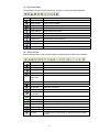
1.5.1 Property Lists
The following table lists the position, size, and other properties that can appear in the
Properties pane.
Note: The list displayed in the Properties pane depends on the part type.
Name
Description
Notes
name
type
Name
Part type
Unique identifier for the part
This is fixed for each part.
x
x-coordinate
y
y-coordinate
Reference position relative to the x- and y-axes within the teach
pendant screen's drawing range
width
Width
Width in pixels relative to the reference corner (x, y)
height
Height
fg
Foreground color
bg
Background color
group
Group number
Group number to which the part belongs
active
Active/inactive setting
Select with the list box.
style
Display style
Select with the list box.
caption
Display string
String to display on part surface
Note: Use the Ctrl+Enter key combination to insert a line break in
multiline text.
fsize
Font size
0: Super small, 1: Small, 2: Medium, 3: Large
justify
Caption positioning
0: Center, 1: Right-justified, 2: Left-justified
thickness
Line width
Line thickness in pixels
Note: The 0 setting produces flood fill.
myGroup
Group number
Unique to a particular group box
state
State
Select ON, OFF, or other state with the list box.
value
Input value
Unique to numerical input boxes
text
Input text
Unique to text boxes
index
Function number
Unique to function keys
interval
Interval
Unique to timers
timeout
Timeout limit
Applicable when no button, line or any other parts are selected.
(A single timeout property per TP panel file can be defined.)
release-mode
RELEASED event
execution condition
Applicable when no button, line or any other parts are selected.
(A single release-mode property per TP panel file can be defined.)
[Version 2.32 or later]
Specify these colors with the list box.
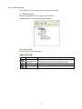
1.5.2 Event List
The Event list box is for selecting a CLICKED, RELEASED, or other state change
event associated with the part.
Note: The events available depend on the part type.
Event
CLICKED
RELEASED
TIMER
REFRESH
INITIALIZE
DONE
Description
Button pressed
Button released
Interval elapsed
Screen refreshed
Initializable TP panel opened [Version 2.32 or later]
OK button pressed [Version 2.32 or later]
17
1.5.3 Action Source Code Syntax
Action source code blocks consist of two kinds of statements:
(1) TP panel control commands
Chapter 4 gives TP panel control language syntax; Section 5.1 "List of TP Panel
Control Commands."
(2) Read/write access to part properties
Note: The properties available depend on the part type.
Such accesses use the standard dot notation: part_name.property.
Example 1: Reading the current state for radio button RadioBtn
DEFINT iState
IState = RadioBtn.State
Example 2: Setting button width to 200
Button.Width = 200
1.5.4 Sending Data to Controller
Use WINCAPSIII to send the created TP panel data to the controller. Before data
transfer, WINCAPSIII compiles the last saved data. If the TP panel data is being edited,
therefore, be sure to save any data modifications before data transfer.
1.5.5 Important Note on Radio Buttons
Makes sure that only one, the default, has ON in its state property. The editor does not
check sets of radio buttons for multiple ON settings. Sending such data to the controller
produces a TP panel screen with multiple ON settings exactly as specified.
18
Chapter 2 Creating TP Panels
Chapter 1 gave an overview of the procedures for arranging objects (parts) on panel
layouts using mouse operations on the computer screen, assigning action source code,
and adjusting their size, position, color, and other properties.
This chapter gives the detailed procedures for creating TP panels. The teach pendant
provides a clean slate on which to display such user-specified panel layouts. A folder
can have only one TP panel file specifying a series of such panel layouts.
2.1
Configuring Teach Pendant
2.1.1 Enabling TP Panel Operation
Add support for TP panel operation to the teach pendant with the following procedure.
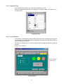
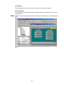
Step 1
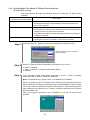
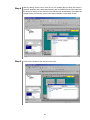
From the teach pendant top screen, press [F6 Set]—[F7 Options.]—[F8 Extnsion]
—[F5 Input ID] to display the following screen.
19
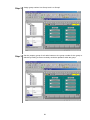
Step 2
Type the password "1453" and press the OK button to display the list of additional
functionality available.
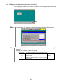
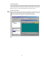
Step 3
Press the OK button to return to the top screen and confirm that the F5 label now
reads Panel.
Press [F5 Panel] to start the TP panel screen software.
Note: Enabling TP panel operation disables the RC5-compatible TP panel operation
assigned to F9.
20
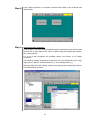
2.1.2 Specifying the Start Mode of TP Panel Screen Software
[Version 2.32 or later]
Note: For Version 2.31 or earlier, see Section 2.1.3 "Automatically Displaying TP Panel
Screens."
The teach pendant provides the following setting for specifying the start mode of TP
panel screen software.
The four choices of the start mode parameters are available by the combination of
"what starts TP panel screen software--booting the controller or pressing [F5 Panel]"
and "which TP panel screen appears first" as listed below.
Start Mode of TP Panel Screen Software
Path of TP panel
screen that
should appear
"0: Panel Start first
Setting"
"1: Start-Panel
Path"
Start mode
parameter
0
--
a) "What starts TP panel screen software"
b) "Which TP panel screen appears at the start"
Remarks
a) Pressing [F5 Panel]
b) Current directory* of the Program List
1
To be specified
a) Booting the controller
b) TP panel screen specified by "Start-Panel
Path"
or
Select this parameter
to run TP panel
screen software
when the controller
boots.
a) Pressing [F5 Panel]
b) Current directory* of the Program List
2
To be specified
a) Pressing [F5 Panel]
b) TP panel screen specified by "Start-Panel
Path"
3
To be specified
Select this parameter
to display the TP
panel screen
predetermined
without changing the
current directory.
a) Booting the controller or Pressing [F5 Panel]
b) TP panel screen specified by "Start-Panel
Path"
*The "Current directory of the Program List" refers to the following.
The current directory is displayed
here.
21
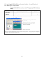
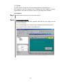
Step 1
Press [F6 Set]—[F7 Options.]—[F9 Panel] to display the following screen.
Parameters relating to the start
mode of TP panel screen
software
Step 2
Set the "0: Panel Start Setting" parameter to any of 0 to 3 (defined on the previous
page).
Step 3
If the "0: Panel Start Setting" parameter is any of 1 to 3, specify the directory where
the desired TP panel screen is located, to the "1: Start-Panel Path" parameter.
Example: TEST
As shown above, delimit the path with backslash " ". This example calls up the TP
panel screen located in the "TEST" folder.
If the "1: Start-Panel Path" parameter is not specified, the root directory (folder at the
top of the directory tree structure) applies.
Note 1: The "1: Start-Panel Path" parameter can only specify a path. If more than one TP panel screen is
defined, the one that is located at the top when complied with Panel Designer will be displayed at the start of
TP panel screen software.
Pressing this changes the order of TP
panels.
The TP panel at the top of the directory
tree structure appears when the controller
boots.
Note 2: After the teach pendant panel screen is switched to a different one located in the Start-Panel Path
(or in the current directory of the Program List) with the PAGE_CHANGE command, exiting from the TP
panel screen software and restarting it calls up the last TP panel screen.
However, after the teach pendant panel screen is switched to a different one located in the path other than
the Start-Panel Path (and the current directory of the Program List), doing the same calls up the TP panel
screen located in the Start-Panel Path (or in the current directory of the Program List) just as when the
controller boots.
22
2.1.3 Automatically Displaying TP Panel Screens [Version 2.31 or earlier]
Note: For Version 2.32 or later, see Section 2.1.2 "Specifying the Start Mode of TP
Panel Screen Software."
The teach pendant provides the following setting for automatically displaying TP panel
screen software when the controller boots.
Step 1
Press [F6 Set]—[F7 Options.]—[F9 Panel] to display the following screen.
Step 2
Set the first setting to 1 to enable automatic loading and the second (path) to the
folder containing the TP panel screen software.
Step 3
Test by rebooting the controller.
Note: An error message on the teach pendant screen blocks automatic display.
23
2.1.4 Specifying the Close Mode of TP Panel Screen Software
[Version 2.32 or later]
The teach pendant provides the following setting for exiting the TP panel screen
software.
Close mode parameter
"2: Operation Panel Close Mode"
Close mode
0
SHIFT + CANCEL (default)
Pressing the Cancel key with the Shift key held down exits the TP
panel screen software.
1
SHIFT + CANCEL + Password
Pressing the Cancel key with the Shift key held down and entering the
password exits the TP panel screen software.
The password should be specified with the password entry parameter
"3: Mode1: Password."
2
CANCEL
Pressing the Cancel key exits the TP panel screen software.
Step 1
Press [F6 Set]—[F7 Options.]—[F9 Panel] to display the following screen.
Specify the close mode of TP panel
screen software.
Step 2
Set the "2: Operation Panel Close Mode" parameter to any of 0 to 2.
0: SHIFT + CANCEL
1: SHIFT + CANCEL + Password (Proceed to Step 3.)
2: CANCEL
Step 3
If the "Operation Panel Close Mode" parameter is set to 1, enter an arbitrary
password to the "3: Mode1: Password" parameter.
Note: The password entry range is from -2147483648 to 2147483647.
When you attempt to exit the TP panel screen software by pressing the Cancel key
with the Shift key held down, the password entry window appears as shown below.
You need to enter the password and press the OK button. If the password entered
here matches the one preset to the "3: Mode1: Password" parameter, the TP panel
screen software exits.
Tip: If you forget the password, enter 273958314 to exit the TP panel screen
software.
24
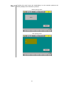
2.1.5 Hiding the Shortcut Button [Version 2.6 or later]
You can hide the SHORTCUT button to prevent it from being pressed inadvertently
when the TP panel screen is active.
SHORTCUT button
Step 1
Press [F6 Set]—[F7 Options.]—[F9 Panel] to display the Panel Setting screen.
Step 2
Select [4: “SHORTCUT” disable] and change the parameter by pressing [F5
Change.].
Pressing the OK button enables the setting.
Parameters for [4: “SHORTCUT” disable] on the Panel Setting screen
Parameter
Description
0
Display the SHORTCUT button when the TP panel
screen is active
1
Hide the SHORTCUT button when the TP panel
screen is active
25
Remarks
Default
2.2
Using Parts
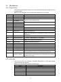
2.2.1 Parts and Their Functions
The following table lists the 14 part types available for building TP panel screen
software.
Parts
(5)
(6)
(7)
(8)
Part
Button
Label
Pilot lamp
Numerical input
box
Text box
Check box
Radio button
Group
(9)
Function key
(10)
Timer
(not shown below)
Line
Oval
Rectangle
Illuminated push
button
(not shown below)
(1)
(2)
(3)
(4)
(11)
(12)
(13)
(14)
Function
Functions as a push button.
Displays text.
Indicates on/off setting.
Accepts a numerical value from the ten-key pad.
Refer to:
Section 2.2.6 [ 1 ]
[2]
[3]
[4]
Accepts text from the keyboard.
Turns setting on and off.
Selects from a group of mutually exclusive choices.
Provides mutually exclusive operation for a group of
radio buttons.
Configures a teach pendant function key (F1 to F12)
for use as a push button.
Triggers action source code at a fixed interval.
[5]
[6]
[7]
[8]
Displays a straight line.
Displays a circle or oval.
Displays a square or rectangle.
Combines push button and pilot lamp operation.
[ 11 ]
[ 12 ]
[ 13 ]
[ 14 ]
[9]
[ 10 ]
Sample TP Panel Screens
(8) Group
(7) Radio buttons
(6) Check boxes
(2) Label
(5) Text box
(13) Rectangle
(4) Numerical input box
(1) Button
(9) Function keys
(3) Pilot lamp
(11) Line
26
(12) Oval
2.2.2 Specifying Action Source Code for Parts
A part on a TP panel screen responds to button presses and other events by executing
action source code that reads or modifies part properties and performs other
operations.
Action Source Code Syntax
An action source code block has the following structure.
DEF object_event
desired operations
END
Selecting an object and an event in the editor automatically generates a skeleton
consisting of the first (DEF) and last (END) lines. The developer needs only supply the
source code specifying the desired response.
The table below lists the possibilities.
Note: The events available depend on the part type.
Event
Description
CLICKED
Button pressed
RELEASED
Button released (See Section 2.2.3.)
TIMER
Interval elapsed
REFRESH
Screen refreshed
INITIALIZE [Version 2.32 or later]
Initializable TP panel opened
DONE
OK button pressed
[Version 2.32 or later]
Action Source Code Statements
Action source code blocks consist of two kinds of statements: TP panel control
commands and read/write accesses to part properties. Accesses use the standard dot
notation: part_name.property.
For a list of part properties and possible values, see Section 3.3.4 "Object Properties."
Action source code blocks can use global variables of type integer, float, double, or
string, local variables, and folder variables.
27
2.2.3 Specifying the RELEASED Event Execution Condition [Version 2.32 or later]
2.2.3.1 Release-mode property added
The release-mode property is added to the property screen, making it possible to
specify the RELEASED event execution condition. The property provides the following
setting.
Release-mode parameter
The RELEASED event executes:
Remarks
0 - Post Event
Even if a press on the part is released outside
the part.
Default in Version 2.32
or later
1 - No Event
Only when a press on the part is released
within the part.
Fixed to this setting in
Version 2.31 or earlier
Specifying the RELEASED event execution condition
Release the press on the part within the part.
(1 - No Event)
Release the press on the part outside the
part by sliding your finger on the screen
surface. (0 - Post Event)
Release-mode property
Note: The release-mode parameter can be contained, one per panel file. Changing the parameter applies
to all parts containing the RELEASED event.
28
2.2.3.2 Notes on using the RELEASED event
The RELEASED event cannot be executed if any other screen appears on the current
TP panel screen. The following example using the push-button shows the detail.
What blocks the execution of the RELEASED event
If any of the following conditions arises when the push-button is being pressed, the
RELEASE event cannot be executed.
(1) When an error occurs.
(2) When the PRINTMSG command displays the message.
(3) When the PAGE_CHANGE command switches TP panel screens, using the timer.
If blocking the execution of the RELEASED event with the above conditions raises a
problem, use a workaround in your program as shown on the next page.
Push-button being pressed
If any of the following conditions arises, releasing the
push-button does not execute the RELEASED event:
(1) When an error occurs.
(2) When the PRINTMSG command displays the message.
(3) When the PAGE_CHANGE command switches TP
panel screens, using the timer.
29
Program example requiring a workaround
The program example given below turns I/O [128] on only when the push-button is
being pressed, so it requires a workaround. (While I/O [128] is on, the external
equipment operates.)
Only when the push-button is being pressed, I/O [128] is on.
Program example
DEF PB1_CLICKED()
set IO[128]
END
DEF PB1_RELEASED()
reset IO[128]
END
Workarounds to the occurrence of errors
(1) Workaround 1
With the supervisory task mode or its extension being enabled, run the following
supervisory task that causes a fail-safe operation (that is, turn I/O [128] off) if an error
occurs. (Refer to the SETTING-UP MANUAL, Chapter 3, Sections 3.4.10 and 3.4.11.)
Program TSR1
DEFINT ERRCODE
INITWAITERR
WHILE 1
ERRCODE=WAITERROR
IF GETERRLVL(ERRCODE)>1
RESET IO[128]
INITWAITERR
ENDIF
WEND
END
'Initialize WAITERROR data.
'Wait until an error occurs.
'If Level 2 or higher error occurs,
'turn I/O[128] off as fail-safe operation.
'Initialize WAITERROR data.
(2) Workaround 2
Use a supervisory task that monitors the deadman switch (Enable switch) state and
add such a process that turns I/O [128] on or off when the deadman switch is pressed
or released, respectively. Accordingly, if an error occurs, releasing the deadman switch
causes a fail-safe operation (turn I/O [128] off).
(3) Workaround 3
Modify the program to turn I/O [128] on for the specified time length when the
push-button is pressed and to cause no change when the push-button is released. This
produces inching-like motion.
Also change the PRINTMSG and PAGE_CHANGE commands to turn I/O [128] on or
off when the switch is pressed or released, respectively.
30
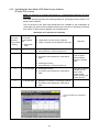
2.2.4 INITIALIZE Event [Version 2.32 or later]
The INITIALIZE event can be added to each panel. It is used to initialize the TP panel
layout.
The INITIALIZE event will be called when any of the following conditions arises.
(1) When pressing [F5 Panel] starts the TP panel screen software.
(2) When booting the controller starts the TP panel screen software.
(3) When the PAGE_CHANGE command switches the TP panel screen.
Step 1
Select a TP panel file, and the INITIALIZE event only becomes available.
Selecting the INITIALIZE event automatically generates a skeleton consisting of the
first (DEF) and last (END) lines as shown below.
DEF Panel_INITIALIZE()
END
Select a TP panel file.
Select INITIALIZE event.
Action source code block
Step 2
Flesh out the skeleton with action source code.
Note: The PAGE_CHANGE command cannot be used for this source code.
31
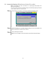
2.2.5 DONE Event [Version 2.32 or later]
The DONE event is added to the "Numerical input box" and "Text box." Pressing the
OK button on the numerical input box or the text box executes the DONE event.
Pressing OK executes the DONE event.
Pressing CANCEL produces nothing.
Example: Numerical input box
Step 1
Select one of the numerical input boxes and select the DONE event.
The action source code block in the following skeleton will be executed.
DEF NB1_DONE()
END
Select one of the numerical input boxes.
Select DONE
event.
The action source
code block
executes.
DONE event example: "IO=NB1.Value"
In this example, pressing the OK button sets the property value of the selected part
to a global variable.
32
2.2.6 Part Descriptions
[ 1 ] Button
This part has two events: CLICKED and RELEASED.
Button Example
The following example illustrates the procedure for creating two buttons: one (labeled
"I/O operation") that turns I/O variable #24 on as long as it is pressed and another
(labeled "Program_run") that runs a program (Sample pro).
Step 1
Create a panel layout with two buttons.
The buttons can go anywhere within the boundaries of the teach pendant screen.
All parts, not just buttons, have a unique name providing read/write accesses to part
properties from the part itself as well as other parts on the same TP panel. The editor
uses as its default Button plus a number, but the developer is free to change names.
The following example simply uses the default names: "Button1" and "Button2."
33
Step 2
Label the buttons by changing their caption properties.
Step 3
Adding action source code
A button has separate action source code blocks for the events CLICKED and
RELEASED. The following example shows how to add action source code for these
two events.
Double-clicking the button labeled "I/O operation" opens an empty Source Code Edit
window.
34
Step 4
Start by adding action source code to turn I/O variable #24 on when the button is
pressed. Selecting the combination Button1 and CLICKED from the Part and Event
list boxes at the top of the Source Code Edit window automatically generates the
corresponding 3-line action source code block skeleton on the editor screen.
Step 5
Flesh out the skeleton with action source code.
35
Step 6
Similarly add action source code to turn I/O variable #24 off when Button1 is
released (RELEASED) and to run a program (Sample pro) when Button2 is pressed
(CLICKED).
Step 7
When the panel layout is complete, save it to disk, and compile the file to check for
syntax, typing, or other errors.
36
Step 8
If the compile operation is successful, download the results to the controller with
WINCAPSIII.
Step 9
Changing button properties
Color, position, and other button properties support read/write access from the part
itself as well as other parts on the same TP panel using the standard dot notation:
part_name.property.
For a list of part properties and possible values, see Section 3.3.4 "Object
Properties."
The following example changes the foreground color (.fg), background color (.bg),
display text (.caption), horizontal position (.x), and vertical position (.y).
Start by loading the editor, adding a button, and opening the corresponding Source
Code Edit window as above.
37
Step 10
Type in the source code as shown below.
Step 11
Save the edits, compile the file, and download the results to the controller as before.
TP Panel Screen with Button Pressed
38
[ 2 ] Label
This part simply displays text. It supports no events, so does not accept action source
code.
Label Example
The following example shows how pressing a button on the same screen can change
label properties.
Step 1
Load the editor and place a label and a button on the panel layout.
39
Step 2
Changing label properties
The label properties for display text, color, font size, and character position support
read/write access using the standard dot notation: part_name.property.
Changing the display text for the part named Label1 to "Off" requires the following
line.
Label1.caption="Off"
Changing the foreground color to yellow, the background color to brown, the font
size to big, and the character position to left-justified requires the following lines.
Label1.fg=yellow
Label1.bg =brown
Label1.fsize=2
Label1.justify=2
Foreground color: Yellow
Background color: Brown
Font size: Big
Character position: Left-justified
Add the above to the skeleton created in the Source Code Edit window for pressing
Button1.
40
Step 3
Compiling this panel layout and downloading it to the controller produces the
following display when the button is pressed.
Before pressing button
After pressing button
41
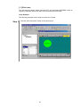
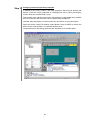
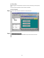
[ 3 ] Pilot Lamp
This part has two display states (ON and OFF) and generates REFRESH events at
regularly scheduled intervals to allow visual monitoring of some state.
Lamp Example
The following example uses a lamp to monitor an I/O state.
Step 1
Load the editor and place a lamp on the panel layout.
42
Step 2
Adding action source code
This part generates REFRESH events at regularly scheduled intervals. Use these to
visually monitor I/O variable #25 by turning the lamp ON and OFF as appropriate. In
the Source Code Edit window, select the lamp's REFRESH event and add the
following line to the skeleton automatically created.
This statement means update the lamp state from the IO[25] state.
43
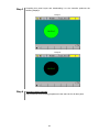
Step 3
Compiling this panel layout and downloading it to the controller produces the
following displays.
Lamp on
Lamp off
Step 4
Changing lamp properties
The procedures for accessing properties are the same as for all other parts.
44
[ 4 ] Numerical Input Box
This part is a button that displays a numerical value. Pressing this button switches the
pendant operation screen to ten-key pad input for directly updating that value.
This part has CLICKED and RELEASED events similar to those for buttons.
Note: In Version 2.32 or later, the DONE event is added to this part. For details, see
Section 2.2.5 "DONE Event."
Numerical Input Box Example
Step 1
Load the editor and place a numerical input box on the panel layout.
(Optional) Specify an initial value.
Step 2
Adding action source code
The procedures for adding action source code are the same as for buttons.
45
Step 3
Changing numerical input box properties
In addition to the color, position, and other properties that this part shares with
buttons, it has the unique properties of a floating-point value (.value) and display
format, decimal or hexadecimal (.style).
This example uses a button press on the same screen to read global string variable
#10 into a text box and store that value in global string variable #11.
Load the editor and place a numerical input box and button on the panel layout.
Open the Source Code Edit window, select Button1 and CLICKED to create the
action source code skeleton, and add the following lines.
The procedures for accessing properties are the same as for all other parts.
46
[ 5 ] Text Box
This part is a button that displays a string. Pressing this button switches the pendant
operation screen to keyboard input for directly updating that string.
This part has CLICKED and RELEASED events similar to those for buttons.
Note: In Version 2.32 or later, the DONE event is added to this part. For details, see
Section 2.2.5 "DONE Event."
Text Box Example
Step 1
Load the editor and place a text box on the panel layout.
(Optional) Specify an initial value.
Step 2
Add action source code
This part has CLICKED and RELEASED events similar to those for buttons.
Step 3
Changing text box properties
In addition to the color, position, and other properties that this part shares with
buttons, this part it has the unique property of a display string (.text).
This example uses a button press on the same screen to read global string variable
#10 into a text box and store that value in global string variable #11.
Load the editor and place a text box and button on the panel layout.
Open the Source Code Edit window, select Button1 and CLICKED to create the
action source code skeleton, and add the following lines.
The procedures for accessing properties are the same as for all other parts.
Textbox1.text=S[10]
S[11]=Textbox1.text
47
[ 6 ] Check Box
This part toggles a setting between on and off. Access to this setting is via the property
state.
This part has other properties similar to buttons and labels.
Check Box Example
Step 1
Load the editor and place a check box on the panel layout.
Step 2
Adding action source code
This part has CLICKED and RELEASED events similar to those for buttons.
48
Step 3
Read/write access to check box properties
This example shows how pressing a button on the same screen can update IO[24]
to IO[26] from a set of check boxes.
Add a button to the panel layout.
49
Step 4
Open the Source Code Edit window, select Button1 and CLICKED to create the
action source code skeleton, and add the following lines for reading the check box
properties (.state).
IO[24] = checkbox1.state
IO[25] = checkbox2.state
IO[26] = checkbox3.state
Compile this panel layout, download it to the controller, and test.
50
[ 7 ] Radio Button
A group (described below) of these parts provides a set of mutually exclusive settings.
These parts have ON/OFF properties (.state) similar to those for lamps and check
boxes.
Radio Button Example
The following example uses radio buttons for three mutually exclusive settings.
Step 1
Load the editor and place a group with three radio buttons on the panel layout.
51
Step 2
Set the property group for all radio buttons to the group number for the group to
ensure mutually exclusive operation of the radio buttons within the group. This
example uses group number 0.
Step 3
Adding action source code
This part has CLICKED and RELEASED events similar to those for buttons.
52
Step 4
Changing radio button properties
Radio buttons have properties similar to those for buttons and labels.
This example shows how pressing a button (Button1) on the same screen can
update both the corresponding output (IO[24] to IO[26]) and a numerical input box
from the corresponding global float variable (F[10] to F[12]) based on the current
states of the radio buttons (RadioButton1 to RadioButton3).
Add the button and numerical input box to the panel layout.
53
Step 5
Open the Source Code Edit window, select Button1 and CLICKED to create the
action source code skeleton, and add the following IF statement branching on the
radio button properties (.state).
If radiobutton1.state=1 then
Io[24] = 1
Numeric1.value = F[10]
Elseif radiobutton2.state=1 then
Io[25] = 1
Numeric2.value = F[11]
Elseif radiobutton3.state=1 then
Io[26] = 1
Numeric1.value = F[12]
End if
Compile this panel layout, download it to the controller, and test.
54
[ 8 ] Group
This part provides mutually exclusive operation for a set of radio buttons.
Group Example
The following example demonstrates mutually exclusive operation with two sets of
radio buttons.
Step 1
Place two groups with three and four radio buttons respectively on the panel layout.
55
Step 2
Assign group number 0 to Group1 and 1 to Group2.
Step 3
Set the property group for all radio buttons to the group number for the group to
which they belong to ensure mutually exclusive operation within the group.
56
[ 9 ] Function Key
This part resembles buttons in assigning captions to pendant function keys and action
source code to function key presses, but it lacks the position properties of other parts
because the pendant function keys have fixed positions, specified by number (.index).
Note: In Version 2.32 or later, the RELEASED event is added to this part.
Function Key Example
Step 1
Load the editor and place the function key anywhere on the panel layout in the
Layout window. Note, however, that the final result will not appear at this position,
but on the corresponding function key on the teach pendant screen.
Specify "Next panel" as the display text (.caption) for the function key.
57
Step 2
Specify the desired function key number (0 to 9). This example uses #2.
Step 3
Adding action source code
This part differs from buttons and other parts in supporting only a single event,
CLICKED.
This example responds to the key press by switching to a different panel, Panel2.
Step 4
Changing function key properties
This part differs from other parts in offering only a single property, caption. Access is
the same as for other parts.
58
[ 10 ] Timer
This part automatically triggers action source code for the TIMER event at the interval
specified by the property interval.
Timer Example
Step 1
Load the editor and place a timer anywhere on the panel layout in the Layout
window. Note, however, that the final result will not appear on the teach pendant
screen.
Step 2
Changing timer properties
The main properties here are active, which controls (and indicates) timer status, and
interval, which controls event frequency.
This example uses buttons to enable and disable a timer which alternately switches
a pilot lamp on and off.
Load the editor and place a timer, two buttons, and a pilot lamp on the panel layout in
the Layout window.
59
Step 3
Adding action source code
Open the Source Code Edit window, select Timer1 and TIMER, create the action
source code skeleton, and add the following line to switch the lamp ON and OFF.
If Lightbutton1.state = 1 then
Lightbutton1.state = 0
Else
Lightbutton1.state = 1
End if
Add the following lines so that the CLICKED events for Button1 ("Start") and Button2
("Stop") respectively enable and disable the timer.
Timer1.active = 1
Timer1.active = 0
60
[ 11 ] Line
This part draws a straight line with the specified pattern on the panel layout.
The parts line, oval, and rectangle are for drawing only. They support no events.
Nevertheless, other parts on the same screen can still change their properties.
Line Example
Step 1
Load the editor and place a line on the panel layout.
Step 2
Changing line properties
Like all drawing parts, the main properties here are line type (.style) and line
thickness (.thickness).
The following example uses a button press to change line thickness and style.
Add a second line and a button to the panel layout.
61
Step 3
Open the Source Code Edit window and add the following action source code for
changing the line 1 thickness to 5 pixels and the line 2 style to dotted line when the
button is pressed.
Step 4
Compiling this panel layout and downloading it to the controller produces the
following displays.
Before button press
After button press
62
[ 12 ] Oval
This part draws an oval with the specified pattern on the panel layout.
The parts line, oval, and rectangle are for drawing only. They support no events.
Nevertheless, other parts on the same screen can still change their properties.
Oval Example
Step 1
Load the editor and place an oval on the panel layout.
Step 2
Changing oval properties
Like all drawing parts, the main properties here are line type (.style) and line
thickness (.thickness).
The procedures for accessing properties are the same as for all other parts.
[ 13 ] Rectangle
This part draws a rectangle with the specified pattern on the panel layout.
The parts line, oval, and rectangle are for drawing only. They support no events.
Nevertheless, other parts on the same screen can still change their properties.
Rectangle Example
Step 1
Load the editor and place a rectangle on the panel layout.
Step 2
Changing rectangle properties
Like all drawing parts, the main properties here are line type (.style) and line
thickness (.thickness).
The procedures for accessing properties are the same as for all other parts.
63
[ 14 ] Illuminated Push Button
An illuminated push button combines button and lamp operation. It therefore supports
CLICKED, RELEASED, and REFRESH events for adding action source code.
The property state gives the lamp's current state just as it does for lamps and check
boxes.
Illuminated Push Button Example
Step 1
Load the editor and place the button just as you would with a regular button.
Step 2
Changing illuminated push button properties
The following example uses illuminated push buttons to run a program and display
an I/O state. Pressing this button runs a program in the same folder. (This program
waits two seconds and then turns IO[24] on.) The lamp in the button tracks IO[24].
Add the necessary parts to the panel layout.
64
Step 3
Adding action source code
This part supports three events for adding action source code: CLICKED,
RELEASED, and REFRESH. This example uses only two.
lbutton1.state = io[24]
Step 4
' copy IO[24] state into Lightbutton1
Write the program to run using WINCAPSIII.
Compile this and the panel layout, download them to the controller, and test.
65
2.3
Interfaces with PAC Language and System
Data exchange between the PAC language and the TP panel is via global and folder
variables.
The interface with the system uses the SYSSTATE command and I/O variables.
2.3.1 Reading and Displaying PAC Variables
A TP panel can access PAC global and folder variables, but not local ones. Folder
variables require EXTERN declarations; global ones do not.
The following examples display such variables on TP panels.
Example Displaying Global Variables
Accessing a global variable uses array notation with the array name indicating the
type: I for integer, F for float, D for double, and S for string. Global integer variable #10,
for example, is I[10].
The following example displays a global variable of each type in a numerical input box
(or text box for the string) when a button is pressed.
Step 1
Load the editor and place a button, three numerical input boxes for displaying the
three numerical variables, and a text box for displaying the string variable on the
panel layout.
66
Step 2
Open the Source Code Edit window and add the following action source code for
when this button is pressed. This example copies global integer variable #10, float
variable #11, and double variable #12 to numerical input boxes and global string
variable #13 to a text box.
Numeric1.value = I[10]
Numeric2.value = F[11]
Numeric3.value = D[12]
Textbox1.text = S[13]
Step 3
Compiling this panel layout and downloading it to the controller produces a display
similar to the following when the button is pressed.
67
Example Displaying Folder Variables
Accessing folder variables in action source code for a button or other part requires first
declaring them with EXTERN plus a reserved word (DEFINT, DEFSNG, DEFDBL, or
DEFSTR) indicating the type. To access folder integer variable itest, for example, the
action source code must first declare it with the following statement.
EXTERN DEFINT itest
The following example displays a folder variable of each type in a numerical input box
(or text box for the string) when a button is pressed.
Step 1
Load the editor and place a button, three numerical input boxes for displaying the
three numerical variables, and a text box for displaying the string variable on the
panel layout.
Note that the layout is identical to that for the global variable example above.
Step 2
Open the Source Code Edit window and add the following action source code for
when this button is pressed. This example copies integer ITEST, float FTEST, and
double DTEST to numerical input boxes and string STEST to a text box.
EXTERN DEFINT ITEST
EXTERN DEFSNG FTEST
EXTERN DEFDBL DTEST
EXTERN DEFSTR STEST
Numeric1.value = ITEST
Numeric2.value = FTEST
Numeric3.value = DTEST
Textbox1.text = STEST
68
2.3.2 Modifying PAC Variables
Modifying PAC variables is simply the write access counterpart of the read access
described in the preceding section.
Example Modifying Global Variables
The following example updates a global variable of each type from the corresponding
numerical input box (or text box for the string) when a button is pressed.
Step 1
Load the editor and place a button, three numerical input boxes for specifying the
three numerical values, and a text box for specifying the string on the panel layout.
69
Step 2
Open the Source Code Edit window and add the following action source code for
when this button is pressed. This example copies the three numerical values to
global integer variable #20, float variable #21, and double variable #22 and the
string to global string variable #23.
I[20]=Numeric1.value
F[21]=Numeric2.value
D[22]=Numeric3.value
S[23]=Textbox1.text
70
Example Modifying Folder Variables
Accessing folder variables in action source code for a button or other part requires first
declaring them with EXTERN plus a reserved word (DEFINT, DEFSNG, DEFDBL, or
DEFSNG) indicating the type.
The following example updates a folder variable of each type from the corresponding
numerical input box (or text box for the string) when a button is pressed.
Step 1
Load the editor and place a button, three numerical input boxes for specifying the
three numerical values, and a text box for specifying the string on the panel layout.
Note that the layout is identical to that for the global variable example above.
Step 2
Open the Source Code Edit window and add the following action source code for
when this button is pressed. This example copies integer ITEST, float FTEST, and
double DTEST to numerical input boxes and string STEST to a text box.
EXTERN DEFINT ITEST
EXTERN DEFSNG FTEST
EXTERN DEFDBL DTEST
EXTERN DEFSTR STEST
ITEST=Numeric1.value
FTEST=Numeric2.value
DTEST=Numeric3.value
STEST=Textbox1.text
71
2.3.3 Reading I/O States
A TP panel can read robot controller I/O states via global I/O variables or local I/O
variables declared with DEFIO. We postpone discussion of the latter to the local
variable description below.
Example Using Global I/O Variables
Accessing a global I/O variable uses array notation with the array name IO.
This example monitors global I/O variables #24 to #27 with lamps updated at regularly
scheduled intervals.
Step 1
Load the editor and place four lamps on the panel layout.
72
Step 2
In the Source Code Edit window, select the REFRESH event for one lamp (This
example uses LightButton1.) and add the following action source code for copying
the I/O states to the lamps at regularly scheduled intervals to the skeleton
automatically created.
LightButton1.state = IO[24]
LightButton2.state = IO[25]
LightButton3.state = IO[26]
LightButton4.state = IO[27]
' copy I/O variable #24 state into LightButton1
' copy I/O variable #25 state into LightButton2
' copy I/O variable #26 state into LightButton3
' copy I/O variable #27 state into LightButton4
73
2.3.4 Modifying I/O States
Use the SET and RESET commands to modify system I/O states.
ON: SET IO[I/O number]
OFF: RESET IO[I/O number]
Example Modifying I/O States
The following example updates I/O variables #28 to #31 from the corresponding check
boxes when a button is pressed.
Step 1
Load the editor and place four check boxes and a button on the panel layout.
74
Step 2
Open the Source Code Edit window and add the following action source code for
updating the outputs from the check boxes.
IO[28]=Checkbox1.state
IO[29]=Checkbox2.state
IO[30]=Checkbox3.state
IO[31]=Checkbox4.state
' update I/O variable #28 from Checkbox1
' update I/O variable #29 from Checkbox2
' update I/O variable #30 from Checkbox3
' update I/O variable #31 from Checkbox4
75
2.3.5 Reading System Status
The SYSSTATE command reads the system status.
For further details on this and other commands, see Chapter 5 "Command Reference."
Example Reading System Status
The following example lights a lamp when the controller is in automatic mode.
Step 1
Load the editor and place a lamp on the panel layout.
76
Step 2
In the Source Code Edit window, select the lamp's REFRESH event and add the
following action source code for updating the lamp based on the mode data read
from the controller at regularly scheduled intervals to the skeleton automatically
created. (This example uses the default name LightButton1.)
DEFINT STAT, AUTOSTAT
STAT=SYSSTATE
AUTOSTAT = &H0010 AND STAT
IF AUTOSTAT = 0 THEN
LIGHTBUTTON1.state = 0
ELSE
LIGHTBUTTON1.STATE = 1
END IF
77
2.4
Switching TP Panels
The PAGE_CHANGE command switches the teach pendant screen to a different TP
panel in the same folder or even one in a different folder. It has the following syntax.
Same folder:
Different folder:
Root folder:
PAGE_CHANGE panel_name
PAGE_CHANGE path_name.panel_name
PAGE_CHANGE \panel_name
2.4.1 Example Switching in Same Folder
The following example has three panel layouts in the same folder with two buttons on
each for freely moving between them.
Step 1
Load the editor, create three panel layouts with two buttons on each, and label the
buttons for the two other panel layouts.
78
Step 2
Open Source Code Edit windows for the panel layouts and add the appropriated line
from the following action source code to each button's CLICKED event.
PAGE_CHANGE PANEL1
PAGE_CHANGE PANEL2
PAGE_CHANGE PANEL3
' switch screen to PANEL1
' switch screen to PANEL2
' switch screen to PANEL3
Compile the panel layouts, download them to the controller, and test.
79
2.4.2 Example Switching Between Folders
The following example has three panel layouts all in different folders in a 3-level
hierarchy with two buttons on each for freely moving between them.
Step 1
Create the 3-level hierarchy with WINCAPSIII.
Load the editor, create three panel layouts, one at each level, with two buttons on
each, and label the buttons for the two other panel layouts.
Step 2
Open Source Code Edit windows for the panel layouts and add the appropriated line
from the following action source code to each button's CLICKED event.
PAGE_CHANGE FOLDER1.PANEL1 ' switch screen to PANEL1 in FOLDER1
relative to the current folder
PAGE_CHANGE FOLDER2.PANEL1 ' switch screen to PANEL1 in FOLDER2
relative to the current folder
PAGE_CHANGE FOLDER1.FOLDER2.PANEL1
' switch screen to PANEL1 in
FOLDER1.FOLDER2 relative to the current
folder
PAGE_CHANGE \PANEL3
' switch screen to PANEL1 in the root folder
using absolute folder reference
80
Step 2
(continued)
Compile the panel layouts, download them to the controller, and test.
81
2.5
Flow Control
The TP panel control language has three types of flow control statements: conditional
branches IF... END IF and IF... THEN... ELSE..., SELECT... CASE, and iteration FOR...
NEXT.
The following sections give examples.
2.5.1 Conditional Branching
Example Using IF... END IF
The following IF statement example reads a global variable into a numerical input box if
an I/O condition is met.
Step 1
Load the editor and place a numerical input box and a button to trigger the test on
the panel layout.
Step 2
Open the Source Code Edit window and add action source code updating the
numerical input box from global integer variable #10 only if I/O variable #24 is 1
when this button is pressed.
Compile the panel layout, download it to the controller, and test.
82
Example Using SELECT... CASE
The following SELECT... CASE example runs a different program according to the
value in a numerical input box when a button is pushed.
Step 1
Load the editor and place a button and a numerical input box on the panel layout.
Step 2
Open the Source Code Edit window and add the following action source code for the
button's CLICKED event.
DEFINT TYPE
TYPE = Numeric1.value
SELECT CASE TYPE
CASE 0
RUN PRO0
CASE 1
RUN PRO1
CASE 2
RUN PRO2
CASE ELSE
RUN PRO10
END SELECT
Compile the panel layout, download it to the controller, and test.
83
2.5.2 Iteration
Example Using FOR...NEXT
The following FOR... NEXT example counts the number of zero values in global integer
variables #0 to #99 when a button is pushed and displays the result in a numerical
input box.
Step 1
Load the editor and place a button and a numerical input box on the panel layout.
Step 2
Open the Source Code Edit window and add the following action source code for the
button's CLICKED event.
DEFINT COUNT,ZEROCOUNT=0
FOR COUNT = 0 TO 99
IF I[COUNT] = 0 THEN
ZEROCOUNT = ZEROCOUNT + 1
END IF
NEXT
NUMERIC1.VALUE = ZEROCOUNT
Compile the panel layout, download it to the controller, and test.
84
2.6
Local Variables
The TP panel control language supports local variables of type integer, float, double,
string, and I/O.
Declaring a variable inside an action source code block makes it local--that is,
accessible only that block.
DEF Button1_CLICKED()
DEF Button1_CLICKED()
DEFINT COUNT,ZEROCOUNT=0
FOR COUNT = 0 TO 99
IF I[COUNT] = 0 THEN
ZEROCOUNT = ZEROCOUNT + 1
END IF
NEXT
NUMERIC1.VALUE = ZEROCOUNT
Valid range for COUNT and
ZEROCOUNT
END
Example Using Local Variables
The following example copies global variables into local ones when a button is pressed,
manipulates the local variables, and copies the results back to the original global
variables.
Step 1
Load the editor and place a button on the panel layout.
85
Step 2
Open the Source Code Edit window and add the following action source code for
* reading global integer variable #10 into a local integer variable, multiplying it by 10,
and writing the result back
* reading global float variable #10 into a local float variable, multiplying it by 20, and
writing the result back
* reading global double variable #10 into a local double variable, multiplying it by 10,
and writing the result back
* reading global string variable #10 into a local string variable, adding "end," and
writing the result back
DEFINT ITEST
DEFSNG FTEST
DEFDBL DTEST
DEFSTR STEST
ITEST = I[10]
FTEST = F[10]
DTEST = D[10]
STEST = S[10]
ITEST = ITEST * 10
FTEST = FTEST * 20
DTEST = DTEST * 10
STEST = STEST + “END”
I[10] = ITEST
F[10] = FTEST
D[10] = DTEST
S[10] = STEST
Compile the panel layout, download it to the controller, and test.
86
Chapter 3 TP Panel Control Language's Structural
Elements
3.1
Language Elements
The TP panel control language has the following structural elements.
3.2
identifier
Name distinguishing a structural element
variable
Temporary storage for data
constant
Data with a fixed value
operator
Symbol indicating an operation on one or two values
expression
Combination of structural elements yielding a value
command
Built-in PAC language instruction
Names
This section sets forth the TP panel control language's rules.
Names representing commands and variables must comply with the following rules.
● Names consist of letters, digits, and underscores. The first character must be a letter.
Note that there is no distinction between upper and lower case.
● The following characters cannot be used in identifiers: period, slash, backslash,
space, colon, semicolon, single quote, double quote, and asterisk.
● Certain characters are used as operators, so cannot be used in identifiers: +, -, *, /,
(, ), etc.
● A space or other delimiter must separate a name from other words on either side.
● The maximum permissible length for a name is 64 characters.
87
3.3
Identifiers and Variables
3.3.1 Variables
Variables represent temporary storage for data. There are global variables, local
variables, and, for TP panel parts, object properties.
A global variable is accessible from all TP panel files.
A local variable is accessible only within the program defining it. Another program
running concurrently may define its own local variable with the same name, but the two
never interact because they are considered entirely separate variables.
An object property is accessible only within the TP panel file defining the object (part).
The following figure illustrates the relationships between parts objects and programs.
3.3.2 Global Variables
These have names consisting of one or two letters indicating the type--I for integer, F
for float, D for double, S for string, and IO for I/O--and a number in brackets ([]). These
names are predefined by the system, so can be used without declarations.
I:
integer, -2147483648 to +2147483647
F: single-precision floating point, -3.402823E+38 to 3.402823E+38
D: double-precision floating point, -1.7976931348623157E+308 to
1.7976931348623157E+308
S: string, up to 243 bytes long
IO: I/O line
Examples: I[1], F[1], D[1], S[1], IO[1]
88
3.3.3 Local Variables
These have the same types as global ones.
I
integer
-2147483648 to +2147483647
F
single-precision floating point
-3.402823E+38 to 3.402823E+38
D
double-precision floating point
-1.7976931348623157E+308 to
1.7976931348623157E+308
S
string
up to 243 bytes long
I/O
I/O line
A local variable must be defined with a type declaration directive before it can be used.
Note: The TP panel control language does not share the PAC language's support for
indirect reference or post-positions.
3.3.4 Object Properties
Object properties provide read/write access to TP panel screen part internals using the
standard dot notation: part_name.property.
Examples:
(1) Change the caption for the part named Button1 to "Button"
(2) Read the state for the part named LightButton1 into I[1]
The following table lists parts, their events, and their properties.
Object Properties for TP Panel Screen Parts
Part Type
Button
Events:
CLICKED,
RELEASED
Property Name
Type
Meaning
Notes
x and y
I
Upper left corner
coordinates
Position relative to the upper left corner of the
drawing region. This corner must be within the
teach pendant drawing range.
width and
height
I
Part dimensions in
pixels
These define the corner opposite the reference
corner (x, y): (x+width, y+height). Negative
means left or up of the reference corner;
positive, right or down.
fg and bg
I
Foreground and
background colors
1: White, 0: Black, 1: Blue, 2: Green, 3: Cyan, 4:
Red, 5: Magenta, 6: Brown, 7: Light Gray, 8:
Gray, 9: Light Blue, 10: Light Green, 11: Light
Cyan, 12: Light Red, 13: Light Magenta, 14:
Yellow
group
I
Group number
Group to which part belongs
active
I
Visible and active
settings
0: Invisible & inactive
Add 1 for visible and 2 for active.
Note that 3 is the only setting producing events.
(CLICKED and RELEASED).
style
I
Display style
0: 2D rectangle, 1: 3D rectangle,
2: 2D oval,
3: 3D oval
caption
S
Display text
String, max. 80 bytes
fsize
I
Font size
0: Tiny, 1: Small, 2: Standard, 3: Big
justify
I
Caption positioning
0: Centered, 1: Right-justified, 2: Left-justified
89
Part Type
Label
Property Name
Type
Notes
x and y
I
Upper left corner
coordinates
Position relative to the upper left corner of the
drawing region. This corner must be within the
teach pendant drawing range.
width and
height
I
Part dimensions in
pixels
These define the corner opposite the reference
corner (x, y): (x+width, y+height). Negative
means left or up of the reference corner;
positive, right or down.
fg and bg
I
Foreground and
background colors
1: White, 0: Black, 1: Blue, 2: Green, 3: Cyan, 4:
Red, 5: Magenta, 6: Brown, 7: Light Gray, 8:
Gray, 9: Light Blue, 10: Light Green, 11: Light
Cyan, 12: Light Red, 13: Light Magenta, 14:
Yellow
group
I
Group number
Group to which part belongs
active
I
Active setting
0: Invisible, 1: Visible
caption
S
Display text
String, max. 80 bytes
fsize
I
Font size
0: Tiny, 1: Small, 2: Standard, 3: Big
justify
I
Caption positioning
0: Centered, 1: Right-justified, 2: Left-justified
x and y
I
Upper left corner
coordinates
Position relative to the upper left corner of the
drawing region. This corner must be within the
teach pendant drawing range.
width and
height
I
Part dimensions in
pixels
These define the corner opposite the reference
corner (x, y): (x+width, y+height). Negative
means left or up of the reference corner;
positive, right or down.
fg and bg
I
Foreground and
background colors
1: White, 0: Black, 1: Blue, 2: Green, 3: Cyan, 4:
Red, 5: Magenta, 6: Brown, 7: Light Gray, 8:
Gray, 9: Light Blue, 10: Light Green, 11: Light
Cyan, 12: Light Red, 13: Light Magenta, 14:
Yellow
group
I
Group number
Group to which part belongs
active
I
Active setting
0: Invisible, 1: Visible
style
I
Display style
0: 2D rectangle,
2: 2D oval,
caption
S
Display text
String, max. 80 bytes
fsize
I
Font size
0: Tiny, 1: Small, 2: Standard, 3: Big
justify
I
Caption positioning
0: Centered, 1: Right-justified, 2: Left-justified
Note: This setting is ignored for style settings 2
and 3.
state
I
State
0: Out, 1: On
Events:
None
Lamp
Meaning
Events:
REFRESH
90
1: 3D rectangle,
3: 3D oval
Part Type
Line
Property Name
Type
Meaning
Notes
x and y
I
Upper left corner
coordinates
Position relative to the upper left corner of the
drawing region. This corner must be within the
teach pendant drawing range.
width and
height
I
Part dimensions in
pixels
These define the corner opposite the reference
corner (x, y): (x+width, y+height). Negative
means left or up of the reference corner;
positive, right or down.
fg and bg
I
Foreground and
background colors
1: White, 0: Black, 1: Blue, 2: Green, 3: Cyan, 4:
Red, 5: Magenta, 6: Brown, 7: Light Gray, 8:
Gray, 9: Light Blue, 10: Light Green, 11: Light
Cyan, 12: Light Red, 13: Light Magenta, 14:
Yellow
group
I
Group number
Group to which part belongs
active
I
Active setting
0: Invisible, 1: Visible
style
I
Display style
0:
Solid line
1 to 7: Dash (dashed line)
8 to 14: Dash double (alternate long and two
short dashed line)
thickness
I
Line thickness
The 0 setting produces a line width of 2.
Numerical
Input
Button
x and y
I
Upper left corner
coordinates
Position relative to the upper left corner of the
drawing region. This corner must be within the
teach pendant drawing range.
Events:
CLICKED,
RELEASED
width and
height
I
Part dimensions in
pixels
These define the corner opposite the reference
corner (x, y): (x+width, y+height). Negative
means left or up of the reference corner;
positive, right or down.
fg and bg
I
Foreground and
background colors
1: White, 0: Black, 1: Blue, 2: Green, 3: Cyan, 4:
Red, 5: Magenta, 6: Brown, 7: Light Gray, 8:
Gray, 9: Light Blue, 10: Light Green, 11: Light
Cyan, 12: Light Red, 13: Light Magenta, 14:
Yellow
group
I
Group number
Group to which part belongs
active
I
Visible and active
settings
0: Invisible & inactive. Add 1 for visible and 2 for
active.
Note that 3 is the only setting producing events.
(CLICKED and RELEASED).
style
I
Display style
0: 2D, 1: 3D
caption
S
Display text
String, max. 80 bytes
fsize
I
Font size
0: Tiny, 1: Small, 2: Standard, 3: Big
justify
I
Caption positioning
0: Centered, 1: Right-justified, 2: Left-justified
value
D
Input value
Equivalent to variable of type double
91
Part Type
Oval
(Circle)
Property Name
Type
Meaning
Notes
x and y
I
Upper left corner
coordinates
Position relative to the upper left corner of the
drawing region. This corner must be within the
teach pendant drawing range.
width and
height
I
Part dimensions in
pixels
These define the corner opposite the reference
corner (x, y): (x+width, y+height). Negative
means left or up of the reference corner;
positive, right or down.
fg and bg
I
Foreground and
background colors
1: White, 0: Black, 1: Blue, 2: Green, 3: Cyan, 4:
Red, 5: Magenta, 6: Brown, 7: Light Gray, 8:
Gray, 9: Light Blue, 10: Light Green, 11: Light
Cyan, 12: Light Red, 13: Light Magenta, 14:
Yellow
group
I
Group number
Group to which part belongs
active
I
Active setting
0: Invisible, 1: Visible
style
I
Display style
0:
Solid line
1 to 7: Dash (dashed line)
8 to 14: Dash double (alternate long and two
short dashed line)
Rectangle
thickness
I
Line thickness
The 0 setting produces flood fill.
x and y
I
Upper left corner
coordinates
Position relative to the upper left corner of the
drawing region. This corner must be within the
teach pendant drawing range.
width and
height
I
Part dimensions in
pixels
These define the corner opposite the reference
corner (x, y): (x+width, y+height). Negative
means left or up of the reference corner;
positive, right or down.
fg and bg
I
Foreground and
background colors
1: White, 0: Black, 1: Blue, 2: Green, 3: Cyan, 4:
Red, 5: Magenta, 6: Brown, 7: Light Gray, 8:
Gray, 9: Light Blue, 10: Light Green, 11: Light
Cyan, 12: Light Red, 13: Light Magenta, 14:
Yellow
group
I
Group number
Group to which part belongs
active
I
Active setting
0: Invisible, 1: Visible
style
I
Display style
0:
Solid line
1 to 7: Dash (dashed line)
8 to 14: Dash double (alternate long and two
short dashed line)
thickness
I
Line thickness
92
The 0 setting produces flood fill.
Part Type
Text Box
Events:
CLICKED,
RELEASED
Group
Property Name
Type
Meaning
Notes
x and y
I
Upper left corner
coordinates
Position relative to the upper left corner of the
drawing region. This corner must be within the
teach pendant drawing range.
width and
height
I
Part dimensions in
pixels
These define the corner opposite the reference
corner (x, y): (x+width, y+height). Negative
means left or up of the reference corner;
positive, right or down.
fg and bg
I
Foreground and
background colors
1: White, 0: Black, 1: Blue, 2: Green, 3: Cyan, 4:
Red, 5: Magenta, 6: Brown, 7: Light Gray, 8:
Gray, 9: Light Blue, 10: Light Green, 11: Light
Cyan, 12: Light Red, 13: Light Magenta, 14:
Yellow
group
I
Group number
Group to which part belongs
active
I
Visible and active
settings
0: Invisible & inactive. Add 1 for visible and 2 for
active.
Note that 3 is the only setting producing events.
(CLICKED and RELEASED).
style
I
Display style
0: 2D, 1: 3D
caption
S
Display text
String, max. 80 bytes
fsize
I
Font size
0: Tiny, 1: Small, 2: Standard, 3: Big
justify
I
Caption positioning
0: Centered, 1: Right-justified, 2: Left-justified
text
S
Input text
Equivalent to variable of type string
x and y
I
Upper left corner
coordinates
Position relative to the upper left corner of the
drawing region. This corner must be within the
teach pendant drawing range.
width and
height
I
Part dimensions in
pixels
These define the corner opposite the reference
corner (x, y): (x+width, y+height). Negative
means left or up of the reference corner;
positive, right or down.
fg and bg
I
Foreground and
background colors
1: White, 0: Black, 1: Blue, 2: Green, 3: Cyan, 4:
Red, 5: Magenta, 6: Brown, 7: Light Gray, 8:
Gray, 9: Light Blue, 10: Light Green, 11: Light
Cyan, 12: Light Red, 13: Light Magenta, 14:
Yellow
group
I
Group number
Group to which part belongs
active
I
Active setting
0: Invisible, 1: Visible
caption
S
Display text
String, max. 80 bytes
fsize
I
Font size
0: Tiny, 1: Small, 2: Standard, 3: Big
justify
I
Caption positioning
0: Centered, 1: Right-justified, 2: Left-justified
thickness
I
Line thickness
The 0 setting produces a line width of 2.
myGroup
I
Group number
Number identifying group
93
Part Type
Check Box
Events:
CLICKED,
RELEASED
Property Name
Type
Meaning
Notes
x and y
I
Upper left corner
coordinates
Position relative to the upper left corner of the
drawing region. This corner must be within the
teach pendant drawing range.
width and
height
I
Part dimensions in
pixels
These define the corner opposite the reference
corner (x, y): (x+width, y+height). Negative
means left or up of the reference corner;
positive, right or down.
fg and bg
I
Foreground and
background colors
1: White, 0: Black, 1: Blue, 2: Green, 3: Cyan, 4:
Red, 5: Magenta, 6: Brown, 7: Light Gray, 8:
Gray, 9: Light Blue, 10: Light Green, 11: Light
Cyan, 12: Light Red, 13: Light Magenta, 14:
Yellow
group
I
Group number
Group to which part belongs
active
I
Visible and active
settings
0: Invisible & inactive. Add 1 for visible and 2 for
active.
Note that 3 is the only setting producing events.
(CLICKED and RELEASED).
style
I
Display style
0: 2D check box
1: 3D check box
2: 3D button
caption
S
Display text
String, max. 80 bytes
Note: Specifying too long a string produces
string overlap on the button surface.
fsize
I
Font size
0: Standard, 1: Small, 2: Big
justify
I
Caption positioning
0: Centered, 1: Right-justified, 2: Left-justified
state
I
State
0: Off, 1: On
94
Part Type
Radio
Button
Events:
CLICKED,
RELEASED
Property Name
Type
Meaning
Notes
x and y
I
Upper left corner
coordinates
Position relative to the upper left corner of the
drawing region. This corner must be within the
teach pendant drawing range.
width and
height
I
Part dimensions in
pixels
These define the corner opposite the reference
corner (x, y): (x+width, y+height). Negative
means left or up of the reference corner;
positive, right or down.
fg and bg
I
Foreground and
background colors
1: White, 0: Black, 1: Blue, 2: Green, 3: Cyan, 4:
Red, 5: Magenta, 6: Brown, 7: Light Gray, 8:
Gray, 9: Light Blue, 10: Light Green, 11: Light
Cyan, 12: Light Red, 13: Light Magenta, 14:
Yellow
group
I
Group number
Group to which part belongs
active
I
Visible and active
settings
0: Invisible & inactive. Add 1 for visible and 2 for
active.
Note that 3 is the only setting producing events.
(CLICKED and RELEASED).
style
I
Display style
0: 2D check box
1: 3D check box
2: 3D button
Function
Key
caption
S
Display text
String, max. 80 bytes
Note: Specifying too long a string produces
string overlap on the button surface.
fsize
I
Font size
0: Tiny, 1: Small, 2: Standard, 3: Big
justify
I
Caption positioning
0: Centered, 1: Right-justified, 2: Left-justified
state
I
State
0: Off, 1: On
caption
S
Display text
String
index
I
Function key
number
1 to 12
x and y
I
Upper left corner
coordinates
Position relative to the upper left corner of the
drawing region. This corner must be within the
teach pendant drawing range.
group
I
Group number
Group to which part belongs
active
I
Active setting
0: Inactive, 1: Active
interval
I
Interval
Spacing, in ms, between events
Events:
CLICKED
Timer
Events:
TIMER
95
Part Type
Illuminated
Push Button
Events:
CLICKED,
RELEASED,
REFRESH
Property Name
Type
Meaning
Notes
x and y
I
Upper left corner
coordinates
Position relative to the upper left corner of the
drawing region. This corner must be within the
teach pendant drawing range.
width and
height
I
Part dimensions in
pixels
These define the corner opposite the reference
corner (x, y): (x+width, y+height). Negative
means left or up of the reference corner;
positive, right or down.
fg and bg
I
Foreground and
background colors
1: White, 0: Black, 1: Blue, 2: Green, 3: Cyan, 4:
Red, 5: Magenta, 6: Brown, 7: Light Gray, 8:
Gray, 9: Light Blue, 10: Light Green, 11: Light
Cyan, 12: Light Red, 13: Light Magenta, 14:
Yellow
group
I
Group number
Group to which part belongs
active
I
Visible and active
settings
0: Invisible & inactive. Add 1 for visible and 2 for
active.
Note that 3 is the only setting producing events.
(CLICKED and RELEASED).
style
I
Display style
0: 2D rectangle,
2: 2D oval,
caption
S
Display text
String, max. 80 bytes
fsize
I
Font size
0: Tiny, 1: Small, 2: Standard, 3: Big
justify
I
Caption positioning
0: Centered, 1: Right-justified, 2: Left-justified
Note: This setting is ignored for style settings 2
and 3.
state
I
State
0: Out, 1: On
1: 3D rectangle,
3: 3D oval
3.3.5 Folder Variables
To access a folder variable declared by a PAC program in the same folder, a TP panel
file must first declare it with an EXTERN declaration.
Example: EXTERN DEFINT AAA ' declare folder variable with name AAA
Read/write access then uses the same syntax as normal variables.
Examples:
AAA = LightButton1.state
I[2] = AAA
' read lamp LightButton1 state into folder variable AAA
' copy contents of folder variable AAA into global
variable I[2]
96
3.4
TP Panel Program
A TP panel program consists solely of action source code blocks with the following
structure.
DEF Object_Event
desired operations
END
Selecting an object and an action in the editor automatically generates a skeleton
consisting of the first (DEF) and last (END) lines. The developer needs only supply the
source code specifying the desired response.
The table below lists the possibilities.
Note: The actions available depend on the part type.
Event
Description
CLICKED
Button pressed
RELEASED
Button released
TIMER
Interval elapsed
REFRESH
Screen refreshed
For further details, see Section 2.2.2 "Specifying Action Source Code for Parts."
One TP panel program cannot access the local variables in another.
3.5
Data Types
The TP panel control language supports three types of data:
(1) String data (S)
A string can be up to 243 bytes long.
(2) Numerical data (I, F, and D)
There are three types here.
I: integer, -2147483648 to +2147483647
F: single-precision floating point, -3.402823E+38 to 3.402823E+38
D: double-precision floating point, -1.7976931348623157E+308 to
1.7976931348623157E+308
(3) I/O data (IO)
I/O data expresses the I/O port status (ON/OFF) as a numeric value.
97
3.6
Type Conversion
Mixing data of different numerical types involves type conversion using the following
rules.
- Assigning a numerical value to a numerical variable of a different type involves first
converting that value to the target variable's type. (implicit casting)
- An expression mixing two numerical values of different types usually involves first
converting the one with lower precision to the type with higher precision. (promoting)
- The only exception to the preceding rule involves bitwise logical operators, which
always convert their operands to integers and yield integer results.
- Converting a floating point value to an integer rounds toward zero, yielding the first
integer between the original value and zero. Examples: 1.23 -> 1 and -1.23 -> -1.
- Assigning a double-precision floating point (double) value to single-precision (float)
one rounds the mantissa off to seven decimal digits.
3.7
Constants
A constant is an expression representing a fixed value.
The TP panel control language supports four types of constants: integer (I), float (F),
double (D), and string (S).
The following describes them individually.
(1) Integer constants
These cover the range -2147483648 to +2147483647.
There are two ways to specify them: in decimal and binary notation. There is no
hexadecimal notation.
Decimal Notation
These are integer constants specified in standard decimal notation.
Examples: 32767, -125, +10
Binary Notation
These are integer constants specified in a binary notation consisting of a prefix (&B)
and a string of binary digits (0 or 1). Using this binary notation, the valid range for
(32-bit) integer constants is &B0 to &B11111111111111111111111111111111.
Examples: &B110, &B0011
98
(2) Float constants
These are single-precision floating point constants with up to 7-digit mantissas over the
range -3.402823E+38 to 3.402823E+38.
There are two ways to specify them: in decimal and exponential (E) notation.
Examples: 1256.3, -9.345E-06
(3) Double constants
These are double-precision floating point constants with up to 15-digit mantissas over
the range -1.79769313486231E+308 to 1.79769313486231E+308.
There are two ways to specify them: in decimal and exponential (E) notation.
Example 1: 1256.325468
This has more than 7 decimal digits, so does not fit in a float.
Example 2: -9.345E-06
(4) String constants
These are constants consisting of up to 128 characters, enclosed in double quotes (").
Example: "PAC"
3.8
Expressions and Operators
Expressions evaluate to a value. An expression can be anything from a single
"element" (constant or variable) to an arithmetic formula combining such elements with
operators. The PAC language offers expressions for all data types that it supports. This
section describes operators and their operations on elements in expressions.
(1) Assignment operator (=)
An assignment statement "assigns" (copies) the result of evaluating the expression on
the right side of this operator to the variable on the left.
99
(2) Arithmetic operators
The following table lists these operators and gives their order of precedence during
expression evaluation.
Arithmetic Operators
Operator
Description
Order of Precedence
^
Exponentiation
Highest
-
Unary minus
*, /
Multiplication and division
MOD
Modulus
+, -
Addition and subtraction
Lowest
Sign of Division Results
Divisor
(right element)
+
0
-
+
+
Error
+
0
0
Error
0
-
-
Error
+
Left element
(3) Relational operators
Relational operators compare two numerical values and return a Boolean result: 1 for
true and 0 for false. The archetypical use is as the conditional expression in a flow
control statement.
Relational Operators
Operator
Description
=
equal
<>
not equal
<
less than
>
greater than
<=
less than or equal
=.
approximately equal
>=
greater than or equal
100
(4) Bitwise logical operators
These operators perform bit arithmetic (logical) operations on the bits of their
operands.
Note that operands are first converted to integers, if necessary.
Bitwise Logical Operators
Operator
Description
NOT
Invert
AND
Logical product
OR
XOR
Logical sum
Mutually exclusive OR
Example: I1 = &B1100 XOR &B0101
The result is &B1001 because the bits differ only in the first and fourth positions.
(5) String operator (+)
This operator concatenates (joins) two strings.
Example: A = "ABC" + "DEF"
String A becomes "ABCDEF."
(6) Order of precedence for arithmetic, bit arithmetic, and relational
operators
The following table gives the order of precedence for mixtures of these operators
during expression evaluation.
Operator
Description
^
Exponentiation
-
Unary minus
*, /
Multiplication and division
MOD
Modulus
+, -
Addition and subtraction
NOT
Invert
AND
Logical product
OR
Logical sum
XOR
Mutually exclusive OR
=, <>, <, >, <=, >=
Relational operators
Order of Precedence
Highest
Lowest
When two operators have the same order of precedence, expression evaluation is
from left to right. To override this behavior, explicitly specify the order of evaluation with
parentheses,
101
Chapter 4 TP Panel Control Language Syntax
4.1
Statements and Lines
A TP panel control language program consists of lines with one statement per line. A
line can be up to 255 bytes long.
A statement is the minimum unit for PAC language programming. It consists of a single
command.
A command consists of the command name plus parameters specifying additional
information to the command.
4.2
Character Set
The TP panel control language uses ASCII letters, digits, and certain special
characters. It does not distinguish between upper and lower case.
These special characters consist of the arithmetic operators (+, -, *, and /) plus the
following.
4.3
comma (,):
Delimiter for parameters
single quote ('):
In-line counterpart of the REM command
double quote ("):
Beginning and end markers for a string constant
space:
Delimiter before and after instruction name
Reserved Words
Command names, the MOD operator, and other words are reserved--that is, have a
preassigned function in processing the TP panel control language, so cannot be used
and names for variables, panels, etc.
TP Panel Reserved Word List
if, then, else, elseif, while, do, return, print, add_widget, msgbox, page_change,
set, reset, run, kill, suspend, suspendall, killall, caption, fg, bg, timeout,
defint, defsng, defdbl, defstr, defio, in, out, break, continue, var, def, pend,
for, refresh, extern, begin, end, wend, next, endif, status, str$, continuerun,
io, i, f, d, s, sysstate, curoptmode, time$, date$, timer, select, case, is, to,
deadmanstate, sprintf$, releasemode, pnlccver, chr$, step
102
4.4
Declaration Directives
These specify names and types for variables, constants, functions, and other items so
that the program can use them. There are three major types.
(1) Type declarations
These specify types for variables and constants.
Type Declaration Directives
Type
Command
Example
integer
DEFINT
DEFINT AA,AB
float
DEFSNG
DEFSNG BA,BB
double
DEFDBL
DEFDBL CA,CB
string
DEFSTR
DEFSTR DA,DB
They can also simultaneously initialize the variables.
Examples:
DEFINT AA = 1
DEFSNG BB(10)
' declare AA as an integer and initialize to 1
' declare BB as a float array with 10 elements
(2) Array declarations
Array declarations use type declaration directives specifying the number of elements.
All types except I/O variables support arrays.
Note, however, that type declaration directives cannot initialize arrays.
Array subscripts start at 0.
An array can have up to three dimensions.
An array can have up to 32767 elements in total.
Example:
DEFINT CC(3,3,3)
' declare CC as 3-dimensional integer array
(3) I/O variable declarations
These assign variable names to specific I/O ports.
I/O Variable Declarations
Type
I/O variable
Command
DEFIO
103
Example
DEFIO PORT = BYTE, 104
4.5
Assignment Statements
An assignment statement "assigns" (copies) a value to a variable of some type.
There are two types.
Numerical: This assigns the result of a numerical expression to a numerical variable.
Example: D[2] = 3.14 ' set D[2] to 3.14
String: This assigns the result of a string expression to a string variable.
Example: S[2] = "DENSO"' set S[2] to "DENSO"
4.6
Flow Control Statements
Flow control statements change statement execution order.
There are three main types.
(1) Conditional branching
IF... THEN... ELSE and IF... END IF statements change execution flow based on
whether the specified condition is satisfied. Execution branches to the statements
following the THEN if the relational expression immediately following the IF evaluates
to TRUE (1) and to those following the ELSE otherwise.
(2) SELECT... CASE
Here execution branches to the CASE line matching the result of evaluating the
specified arithmetic expression on the SELECT line, executing the statement block
between that CASE line and the next one (or END SELECT line). If there is no such
match, execution branches to the CASE ELSE block.
(3) Iteration
Here execution of the statement block between the FOR and NEXT lines repeats as
long as the condition specified on the FOR line remains satisfied.
104
4.7
I/O Control Statements
There are three types here.
(1) DI and DO control statements
These directly control I/O ports.
DI/DO Commands
Command
Description
IN
Read data from the I/O port designated by an I/O variable.
OUT
Output data to the I/O port designated by an I/O variable.
SET
Set an I/O port to ON.
RESET
Set an I/O port to OFF.
(2) Teach pendant control statements
These control teach pendant screen I/O.
Teach Pendant Commands
Command
4.8
Description
MSGBOX
Display message screen.
PAGE_CHANGE
Display the specified TP panel.
REFRESH
Redraw screen.
Task Control Statements
These control the multitasking of tasks other than the one containing the statement.
Task Control Commands
Command
Description
RUN
Create/initiate task.
SUSPEND
Interrupt task.
KILL
Delete task.
SUSPENDALL
Interrupt all tasks.
KILLALL
Delete all tasks.
CONTINUERUN
Resume suspended task.
105
4.9
Functions
The following string functions are available.
String Functions
Function
Description
STR$
Convert a value to a character string.
CHR$
Specify a character using a numeric code.
4.10 System Information
The following commands return system information.
System Information Commands
Command
Description
STATUS
Obtain the program status.
CUROPTMODE
Get the current operation mode.
SYSSTATE
Get the system status of the robot controller.
4.11 Preprocessor
A preprocessor statement controls string substitution or file fetch in compiling
programs--that is, translating them into executable form.
Preprocessor Commands
Command
Description
#define
Define macro (symbolic name) for constant or string.
#include
Insert the specified file at this point.
106
Chapter 5 Command Reference
5.1
List of TP Panel Control Commands
Classified by functions
Declaration Statements
Local Variable
Integer
Floating-point
Commands
Declare an integer type variable. The range of the
integer is from -2147483648 to 2147483647.
~
~
DEFSNG
Declare a single precision real type variable. The
range of single precision real variables is from
-3.402823E+38 to 3.402823E+38.
Declare a double precision real type variable. The
range of double precision real type variables is from
-1.79769313486231D + 308 to
1.79769313486231D + 308.
Declare a character string type variable. You can
enter 247 characters or less as a character string.
Declare an I/O variable corresponding to the
input/output port.
~
~
~
~
~
~
~
~
Repeatedly execute a series of instructions
between FOR…NEXT sections.
Conditionally decide a conditional expression
between IF…END IF.
Execute a plural condition decision.
~
~
~
~
~
~
Read data from the I/O port designated by an I/O
variable.
Output data to the I/O port designated by an I/O
variable.
Set an I/O port to ON.
Set an I/O port to OFF.
Display message screen.
Display the specified TP panel.
~
~
~
~
~
~
~
~
~
~
~
~
~
~
~
~
~
~
~
~
~
~
DEADMANSTATE
Concurrently run another program.
Forcibly terminate a task.
Suspend a task.
Suspend all running programs except supervisory
tasks.
Forcibly terminate all tasks except supervisory
tasks.
Continue-run tasks.
Obtain the current deadman switch state.
~
~
~
~
OFF
ON
PI
FALSE
TRUE
Set an OFF (0) value.
Set an ON (1) value.
Set a π value.
Set a value of false (0) to a Boolean value.
Set a value of true (1) to a Boolean value.
~
~
~
~
~
~
~
~
~
~
DATE$
TIME$
TIMER
Obtain the current date.
Obtain the current time.
Obtain the elapsed time.
~
~
~
~
~
~
DEFDBL
String
DEFSTR
I/O
DEFIO
Flow Control Statements
Repeat
FOR…NEXT
IF…END IF
SELECT CASE
Input/Output Control
Statements
I/O Port
IN
OUT
TP Panel
Multitasking Control
Statements
Task Control
SET
RESET
MSGBOX
PAGE_CHANGE
RUN
KILL
SUSPEND
SUSPENDALL
KILLALL
CONTINUERUN
Constants
Built-in Constants
Time/Date Control
Time/Date
4-axis 6-axis
DEFINT
Double-precision
Conditional Branch
Functions
107
Classified by functions
Commands
Functions
4-axis 6-axis
Functions
System Information
Operation Mode
Preprocessor
Symbol Constants
Macro Definitions
File Fetch
STR$
CHR$
SPRINTF$
Convert a value to a character string.
Convert an ASCII code to a character.
Convert an expression to a designated format and
returns it as a character string.
~
~
~
~
~
~
CUROPTMODE
SYSSTATE
STATUS
Get the current operation mode.
Get the system status of the robot controller.
Obtain the program status.
~
~
~
~
~
~
#define
Replace a designated constant or macro name in
the program with a designated character string.
Fetch the preprocessor program.
~
~
~
~
#include
108
5.2
Declaration Statements
DEFINT (Statement)
Function
Declare an integer variable within the range from −2147483648 to 2147483647.
Format
DEFINT <Variablename>[=<Constant>][,<Variablename>[=<Constant>]...]
Explanation
This statement declares the variable designated by <Variablename> as the integer
type variable. By writing a constant after <Variablename>, initialization can be carried
out simultaneously with the declaration.
Multiple variable names can be declared at a time by delineating the names using ",".
Related Terms
DEFDBL, DEFSNG, DEFSTR
Example
DEFINT lix, liy, liz
DEFINT lix = 1
'Declare lix, liy, and liz as integer type variables.
'Declare lix as an integer type variable and set
'the initial value to 1.
DEFSNG (Statement)
Function
Declare a single precision real type variable.
The range of single precision real variables is from -3.402823E+38 to 3.402823E+38.
Format
DEFSNG <Variablename>[=<Constant>][,<Variablename>[=<Constant>]...]
Explanation
This statement declares a variable designated by <Variablename> as a single
precision real type variable. By writing a constant after <Variablename>, initialization
can be done simultaneously with the declaration.
Multiple variable names can be declared at a time by separating them with a comma
",".
Related Terms
DEFDBL, DEFINT, DEFSTR
Example
DEFSNG lfx, lfy, lfz
DEFSNG lfx = 1.0
'Declare lfx, lfy, and lfz as single precision real type
'variables.
'Declare lfx as a single precision real type variables and
'set the initial value to 1.0.
109
DEFDBL (Statement)
Function
Declare a double-precision variable of type real.
The range of double precision real type variables is from -1.79769313486231D + 308
to 1.79769313486231D + 308.
Format
DEFDBL <Variablename>[=<Constant>][,<Variablename>[=<Constant>]...]
Explanation
This statement declares the variable designated by <Variablename> as a double
precision real type variable. By writing a constant after <Variablename>, initialization
can be performed simultaneously with the declaration.
Multiple variable names can be declared at a time by separating each variable name
by a comma (",").
Related Terms
DEFINT, DEFSNG, DEFSTR
Example
DEFDBL ldx, ldy, ldz
DEFDBL ldx = 1.0
'Declare ldx, ldy, and ldz as double precision real type
'variables.
'Declare ldx as a double precision real type variable and
'sets the initial value to 1.0.
DEFSTR (Statement)
Function
Declare a string variable.
You can enter 243 characters or less as a character string.
Format
DEFSTR <Variablename>[=<Constant>][,<Variablename>[=<Constant>]...]
Explanation
This statement declares a variable designated by <Variablename> as a character
string. By writing a constant after <Variablename>, initialization can be done
simultaneously with the declaration.
Multiple variable names can be declared at a time by separating each variable with a
comma (",").
Related Terms
DEFDBL, DEFINT, DEFSNG
Example
DEFSTR lsx, lsy, lsz
DEFSTR lsx = "DENSO"
'Declare lsx, lsy, and lsz as character string type
'variables.
'Declare lsx as a character string type variable and set
'the initial value to "DENSO".
110
DEFIO (Statement)
Function
Declare an I/O variable corresponding to the input/output port.
Format
DEFIO <Variablename> = <I/O variable type>,<Port address>[,<Mask data>]
Explanation
This statement declares a variable designated by <Variable name> as an I/O variable.
<I/O variable type> Selects the type of the I/O variable. The I/O variable types include
BIT, BYTE, WORD and INTEGER. Designate a range of 1 bit for a
BIT type, 8 bits for a BYTE type, 16 bits for a WORD type and 32
bits for an INTEGER type.
<Port address>
Designates the starting input/output port number.
<Mask data>
In the case of an input port, the AND (product set) from input data
and mask data is taken.
In the case of an output port, the AND (product set) from output data and mask data is
output, however, the output status of a bit where no mask has been set does not
change.
Related Terms
IN, OUT, SET, RESET
Example
DEFIO samp1 = BIT, 1
'Declare samp1 as a BIT type I/O variable which starts from
'port 1. The return value of samp1 becomes a 1-bit integer
'of 1 or 0 that expresses the status of port 1.
DEFIO samp2 = BYTE, 10, &B00010000
'Declare samp2 with mask data as a BYTE type I/O
'variable which starts from port 10. The return value of
'samp2 becomes an 8-bit integer of 0 or 16 that expresses
'the status of port 10.
DEFIO samp3 = WORD, 15
'Declare samp3 as a WORD type I/O variable which starts
'from port 15. The return value of samp3 becomes a 16-bit
'integer of 0 to &Hffff which expresses the status of the ports
'from 15 to 30.
DEFIO samp4 = INTEGER, 1
'Declare samp4 as an INTEGER type I/O variable which
'starts from port 1. The return value of samp4 becomes a
'32-bit integer of 0 to &Hffffffff which expresses the
'status of the ports from 1 to 32.
Notes
For WORD and INTEGER, a port used as the MSB is assumed to be a sign bit.
The table below lists the allowable range of numeric values and pot numbers used as
the MSB.
WORD
Allowable range of numeric values: -32768 to 32767
MSB port No.: Starting port address + 15
INTEGER
Allowable range of numeric values: -2147483648 to 2147483647
MSB port No.: Starting port address + 31
111
5.3
Flow Control Statements
FOR…NEXT (Statement)
Function
Repeatedly execute a series of instructions between FOR…NEXT sections.
Format
FOR <Variablename> = <Initial value> TO <Final value> [STEP <Increment>]
:
NEXT [<Variablename>]
Explanation
This statement repeatedly executes a series of instructions between FOR…NEXT
according to the condition designated on the FOR line.
Set the initial value of the variable designated by <Variablename> for <Initial value>.
Set the final value of the variable designated by <Variablename> for <Final value>.
Set an increment value between the initial value and the final value for <Increment>.
Omitting STEP regards the increment as 1. No negative value can be specified for
<Increment>.
You can put another FOR…NEXT in one FOR…NEXT (referred to as a nested
construction).
In this case, a different variable must be used for each <Variablename>. Additionally,
one FOR…NEXT must be completely inside the other FOR…NEXT.
Example
DEFINT li1
FOR li1 = 1 TO 5
'Repeat the process of FOR…NEXT 5 times.
NEXT
'Repeat.
112
IF…END IF (Statement)
Function
Conditionally decide a conditional expression between IF…END IF.
Format
IF <Conditional expression> THEN
:
[ELSEIF <Conditional expression> THEN]
:
[ELSE]
:
END IF
Explanation
The execution of a program is controlled with the condition of <Conditional
expression>.
If <Conditional expression> of an IF statement is true (except for 0), then the
statements between the IF…ELSEIF statement are executed. If the <Conditional
expression> is false (0), then <Conditional expression> of an ELSE IF statement is
decided. In the same manner as this, ELSEIF
ELSE and ELSE…END IF are
executed.
Related Terms
IF…THEN…ELSE
Example
DIM li1 As Integer
IF li1 = 0 THEN
PAGE_CHANGE PANEL1
ELSEIF li1 = 1 THEN
PAGE_CHANGE PANEL2
ELSEIF li1 = 2 THEN
PAGE_CHANGE PANEL3
ELSE
PAGE_CHANGE PANEL4
END IF
'When li1 is 0,
'move to PANEL1.
'When li1 is 1,
'move to PANEL2.
'When li1 is 2,
'move to PANEL3.
'When li1 is any other value,
'move to PANEL4.
'Declare the end to the IF statement.
113
SELECT CASE (Statement)
Function
Execute a plural condition decision.
Format
SELECT CASE <Expression>
CASE <Item>[,<Item>...]
:
[CASE ELSE]
END SELECT
Explanation
This statement executes a series of instructions after CASE if the value of
<Expression> matches <Item> of the CASE statement.
An arithmetic expression or character string can be designated for <Expression>.
A variable, a constant, an expression or a conditional expression can be designated for
<Item>.
A conditional expression can be designated as follows.
• <Arithmetic expression 1> TO < Arithmetic expression 2>
The result of <Expression> is checked if it is <Arithmetic expression 1> or higher, or if
it is <Arithmetic expression 2> or lower.
This statement cannot be used in the case of a character string.
• IS <Comparison operator><Arithmetic expression>
The result of <Expression> and the value of <Arithmetic expression> are compared.
In the case of a character string, <Comparison operator> is " = ".
A CASE ELSE statement is executed if all CASE statements are not satisfied.
A CASE ELSE statement must be put before an END SELECT statement.
Related Terms
IF…END IF
Example
SELECT CASE Index
CASE 0
Button1.caption
CASE 1
Button1.caption
CASE 2
Button1.caption
CASE 3
Button1.caption
CASE 4
Button1.caption
CASE 5
Button1.caption
CASE 6 TO 8
Button1.caption
CASE IS ≥ 9
Button1.caption
END SELECT
=
=
=
=
=
=
=
=
'Execute this command if the index value matches the CASE
'statement value.
'If the index is 0.
"0"
'If the index is 1.
"1"
'If the index is 2.
"2"
'If n the index is 3.
"3"
'If the index is 4.
"4"
'If the index is 5.
"5"
'If the index is 6 to 8.
"6-8"
'If the index is 9 or more.
"9-"
'Declare the end of the plural conditional decision statement.
114
5.4
Input/Output Control Statements
IN (Statement)
Function
Read data from the I/O port designated by an I/O variable.
Format
IN <Arithmetic variablename> = <I/O variable>
Explanation
This statement assigns the I/O port data designated by <I/O variable> to the variable
designated by <Arithmetic variablename>.
The <I/O variable> is declared using a DEFIO statement or an I/O type variable.
Related Terms
OUT, DEFIO
Example
DEFINT Li1, Li2
DEFIO samp1 = INTEGER, 220
IN Li1 = samp1
IN Li2 = IO[240]
OUT samp1 = Li1
OUT IO[240] = Li2
'Declare samp1 as an INTEGER type I/O variable
'beginning at port 220.
'Assign the samp1 data to Li1.
'Assign the port 240 data to Li2.
'Output the Li1 data from the port declared in samp1.
'Output the Li2 data from port 240.
OUT (Statement)
Function
Output data to the I/O port designated by an I/O variable.
Format
OUT <I/O variable> = <Output data>
Explanation
This statement outputs the value of <Output data> to the port address designated by
<I/O variable>.
<I/O variable> is declared using a DEFIO statement or I/O type variable.
Related Terms
IN, DEFIO
Example
DEFINT Li1, Li2
DEFIO samp1 = INTEGER, 220
IN Li1 = samp1
IN Li2 = IO[240]
OUT samp1 = Li1
OUT IO[240] = Li2
'Declare samp1 as an INTEGER type I/O variable
'beginning at port 220.
'Assign the samp1 data to Li1.
'Assign the port 240 data to Li2.
'Output the Li1 data from the port declared in samp1.
'Output the Li2 data from port 240.
115
SET (Statement)
Function
Set an I/O port to ON.
Format
SET <I/O variable>[,<Output time>]
Explanation
This statement sets the designated port in <I/O variable> to ON.
If <Output time> is designated a pulse is output. (The output time unit is ms.)
If <Output time> is designated the system does not proceed to the next instruction until
this time elapses. The specified output time value is the minimum output time while the
actual output time will change according to task priority.
Related Terms
RESET, DEFIO
Example
SET IO[240]
SET IO[SOL1]
SET IO[104 TO 110]
IF IO[242] THEN
RESET IO[240]
RESET IO[SOL1]
RESET IO[104 TO 110]
ENDIF
'Set BIT port 240 to ON.
'Set port specified by I/O variable SOL1 to ON.
'Set BIT ports 104 to 110 to ON.
'Set BIT port 240 to OFF.
'Set port specified by I/O variable SOL1 to OFF.
'Set BIT ports 104 to 110 to OFF.
RESET (Statement)
Function
Set an I/O port to OFF.
Format
RESET <I/O variable>
Explanation
This statement sets the port specified by <I/O variable> to OFF.
Related Terms
SET, DEFIO
Example
SET IO[240]
SET IO[241],40
SET IO[SOL1]
SET IO[104 TO 110]
IF IO[242] THEN
RESET IO[240]
RESET IO[SOL1]
RESET IO[104 TO 110]
ENDIF
'Set
'Set
'Set
'Set
BIT port 240 to ON.
BIT port 241 to ON for 40 ms.
port specified by I/O variable SOL1 to ON.
BIT ports 104 to 110 to ON.
'Set BIT ports 104 to 110 to OFF.
'Set port specified by I/O variable SOL1 to OFF.
'Set BIT ports 104 to 110 to OFF.
116
MSGBOX (Statement)
Function
Display message screen.
Format
MSGBOX <message_string>
Explanation
This statement displays the specified message, up to 60 characters long, on the teach
pendant's color LCD screen.
Related Terms
MSGBOX "Hello World !"
Notes
This statement does nothing in a CLICKED event source code block for parts
(numerical input box and text box) using pop-up windows.
PAGE_CHANGE (Statement)
Function
Display the specified TP panel.
Format
PAGE_CHANGE <panel_name> [, <folders_up>]
where
<panel_name>
TP panel to display on the teach pendant's color LCD screen
<folders_up>
Number of folder levels to step up to reach the folder containing the
specified TP panel
Explanation
This statement displays the specified TP panel on the teach pendant's color LCD
screen.
Example
page_change panel1
page_change panel1,2
'Display specified TP panel
'Move up two folders and display panel1 in that folder
117
5.5
Multitasking Control Statements
RUN (Statement)
Function
Run another program concurrently.
Format
RUN <Programname> [(<Argument>[,<Argument>…])][,<RUN option>]
Explanation
This statement allows the currently executed program to run a program designated in
<Programname>. However, the current program cannot run the program itself.
Only values are usable for <Argument>. Even if you specify reference pass, the
reference data will automatically be changed to values. But you cannot use local array.
For <RUN option>, there are PRIORITY (or P) and CYCLE (or C).
PRIORITY (or P)
Designates the priority of a program. If ignored, the default value of 128 is set. The
smaller the value, the higher the level of priority. The setting range is from 102 to 255.
Note: The priority over of the supervisory task cannot be changed.
CYCLE (or C)
Designates an alternate cycle (time of each cycle when a program is run repeatedly).
This option is expressed in msec. The setting range is from 1 to 2,147,483,647.
You cannot start any program that includes arguments when using the cycle option.
Example
DEFINT Li1 = 1, Li2 =2, Li3 = 3
RUN samp1 C=1000
'Runs samp1 in parallel n (C=1000).
RUN samp2(Li1)
'Runs samp2 using the Li1 argument in parallel.
RUN samp3(Li1,Li2),PRIORITY = 129
'Runs samp3 using the Li1 and Li2 arguments in parallel
'(P = 129).
RUN samp4(Li1,Li2),PRIORITY = 150
'Runs samp4 using the Li1 and Li2 arguments in parallel
'(P = 150).
RUN samp5(Li1,Li2,Li3),P = 120
'Runs samp5 using the Li1, Li2, and Li3 arguments in parallel
'(P = 120)
118
KILL (Statement)
Function
Forcibly terminate a task.
Format
KILL <Programname>
Explanation
This statement forcibly terminates the task (program) designated by <Programname>.
However, it cannot kill a program that contains the statement. If attempted, an error will
occur. To forcibly terminate a statement-containing program, use a STOP instruction.
Related Terms
SUSPEND
Example
RUN samp1
.
.
.
KILL samp1
'Concurrently runs samp1.
'Ends samp1.
SUSPEND (Statement)
Function
Suspend a task.
Format
SUSPEND <Programname>
Explanation
This statement suspends the processing of a designated task. However, it cannot
suspend a program that contains the statement.
Related Terms
KILL
Example
SUSPEND samp1
'Suspend task execution of samp1.
119
SUSPENDALL (Statement)
Function
Suspend all running programs except supervisory tasks.
Format
SUSPENDALL
Explanation
This statement suspends all tasks except supervisory tasks, makes them enter the
"Continue Stop" state, and turns off the "Robot-in-operation" output signal.
Related Terms
SUSPEND, KILLALL
Example
SUSPENDALL
'Immediately stop all tasks and enter "Continue Stop" status.
KILLALL (Statement)
Function
Forcibly terminate all tasks except supervisory tasks. (Functionally equivalent to the
"Program reset" command)
Format
KILLALL
Explanation
This statement forcibly terminates all tasks except supervisory tasks and turns off the
"Robot-in-operation" output signal.
Related Terms
KILL, SUSPENDALL
Example
KILLALL
'Terminate all tasks and enter the program reset state.
120
CONTINUERUN (Statement)
Function
Continue-run tasks.
Format
CONTINUERUN
Explanation
Restarts all continue-stopped tasks from the subsequent steps.
Related Terms
KILL, SUSPENDALL
Example
CONTINUERUN
'Restart all tasks.
DEADMANSTATE (Statement)
Function
Obtain the current deadman switch state.
0: OFF, 1: ON taka
Format
DEADMANSTATE
Explanation
This statement gets the current state of the deadman switch (Enable switch).
Example
IO = DEADMANSTATE
'Assign the current deadman state to I0.
121
5.6
Constants
OFF (Built-in constant)
Function
Set an OFF (0) value.
Format
OFF
Explanation
This statement sets an OFF (0) value in an expression.
Related Terms
ON
Example
1F I1 = TRUE THEN
'Set the Boolean value to true (1).
I1 = ON
'Set ON (1) to the integer variable.
ELSEIF I1 = FALSE THEN 'Set the Boolean value to true (1).
I1 = OFF
'Set OFF (0) to the integer variable.
ELSE
D1 = PI
'Assign π to the real variable.
ENDIF
ON (Built-in constant)
Function
Set an ON (1) value.
Format
ON
Explanation
This statement sets an ON (1) value in an expression.
Related Terms
OFF
Example
1F I1 = TRUE THEN
'Set the Boolean value to true (1).
I1 = ON
'Set ON (1) to the integer variable.
ELSEIF I1 = FALSE THEN 'Set the Boolean value to true (1).
I1 = OFF
'Set OFF (0) to the integer variable.
ELSE
D1 = P
'Assign π to the real variable.
ENDIF
122
PI (Built-in constant)
Function
Set a π value.
Format
PI
Explanation
This statement returns a double-precision value of π.
Example
1F I1 = TRUE THEN
'Set the Boolean value to true (1).
I1 = ON
'Set ON (1) to the integer variable.
ELSEIF I1 = FALSE THEN 'Set the Boolean value to true (1).
I1 = OFF
'Set OFF (0) to the integer variable.
ELSE
D1 = PI
'Assign π to the real variable.
ENDIF
FALSE (Built-in constant)
Function
Set a value of false (0) to a Boolean value.
Format
FALSE
Explanation
This statement sets a value of false (0) to a Boolean value in an expression.
Related Terms
TRUE
Example
1F I1 = TRUE THEN
'Set the Boolean value to true (1).
I1 = ON
'Set ON (1) to the integer variable.
ELSEIF I1 = FALSE THEN 'Set the Boolean value to true (1).
I1 = OFF
'Set OFF (0) to the integer variable.
ELSE
D1 = PI
'Assign π to the real variable.
ENDIF
123
TRUE (Built-in constant)
Function
Set a value of true (1) to a Boolean value.
Format
TRUE
Explanation
This statement sets a value of true (1) to a Boolean value.
Related Terms
FALSE
Example
1F I1 = TRUE THEN
'Set the Boolean value to true (1).
I1 = ON
'Set ON (1) to the integer variable.
ELSEIF I1 = FALSE THEN 'Set the Boolean value to true (1).
I1 = OFF
'Set OFF (0) to the integer variable.
ELSE
D1 = PI
'Assign π to the real variable.
ENDIF
124
5.7
Time/Date Control
DATE$ (System Variable)
Function
Obtain the current date.
Format
DATE$
Explanation
This statement stores the current date in the following format: "yyyy/mm/dd"
(year/month/day).
Related Terms
TIME$
Example
defstr ls1
ls1 = DATE$
'Assign the current date to ls1.
TIME$ (System Variable)
Function
Obtain the current time.
Format
TIME$
Explanation
This statement stores the current time in the following format: "hh:mm:ss" (Time:
minute: second).
Time is displayed using the 24 hour system.
Related Terms
DATE$
Example
defstr ls1
ls1 = TIME$
'Assign the current time to ls1.
125
TIMER (System Variable)
Function
Obtain the elapsed time.
Format
TIMER
Explanation
This statement obtains the elapsed time, measured in milliseconds from the time, when
the controller power is ON (0).
Note: If the elapsed time exceeds 2147483647 milliseconds, the elapsed
time will be displayed from -2147483648 milliseconds.
Example
DEFINT li1, li2, li3
li1 = TIMER
'Assign the elapsed time from the reference time to li1.
126
5.8
Character String Functions
STR$ (Function)
Function
Convert a value to a character string.
Format
STR$ (<Expression>)
Explanation
This statement converts the value designated in <Expression> to a character string.
Related Terms
CHR$, SPRINTF$
Example
DEFSTR ls1, ls2
ls1 = STR$(20)
ls2 = STR$(li1)
'Convert 20 to a string and assign it to ls1.
'Convert li1 to a string and assign it to ls2.
CHR$ (Function)
Function
Convert an ASCII code to a character.
Format
CHR$ (<Expression>)
Explanation
This statement obtains a character with the character code of the value designated in
<Expression>.
Related Terms
STR$
Example
DEFSTR ls1, ls2
ls1 = CHR$(49)
'Assign a character with the character code of 49 to ls1.
ls2 = CHR$(&H4E)
'Assign a character with the character code of &H4E to ls2.
PB1.caption = "program" + CHR$(13) + CHR$(10) + "start"
'Use CR-LF combination as a line delimiter for captions.
127
SPRINTF$ (Function)
Function
Convert an expression to a designated format and returns it as a character string.
Format
SPRINTF$ (<Format>, <Expression>)
Related Terms
STR$
Example
SO = SPRINTF$("% d",123)
'Assign "123" to S0.
128
5.9
System Information
CUROPTMODE (Statement)
Function
Get the current operation mode.
Format
CUROPTMODE
Explanation
This statement gets the current operation mode as a value (any of 1 to 4 shown below).
1: Manual, 2: Teach check, 3: Internal auto, 4: External auto
Example
I[1] = CUROPTMODE
'Get the current operation mode.
SYSSTATE (Statement)
Function
Get the system status of the robot controller.
Format
SYSSTATE
Explanation
This statement gets the system status of the robot controller. The status data differs
depending upon the I/O line assignment. Listed below are data that can be obtained.
Bit 0
1
2
3
Robot-in-operation signal
Robot failure signal
Servo ON signal
Robot initialization complete signal (in the I/O standard mode)
Robot power on complete signal (in the I/O compatible mode)
4
Auto mode signal
5
External mode signal
6
Dead battery warning signal
7
Robot warning signal
8
Continue start permitted signal
9
SS mode signal
10
Robot stop signal
11
Enable Auto signal
12 to 15 Reserved.
16
Program start reset signal (in the I/O compatible mode)
17
CAL complete signal (in the I/O compatible mode)
18
Teaching signal (in the I/O compatible mode)
19
Single-cycle end signal (in the I/O compatible mode)
20 to 23 Reserved.
24
Command processing complete signal (in the I/O standard mode)
25 to 31 Reserved.
Example
I[1] = SYSSTATE
'Get the system status of robot controller.
129
STATUS (Function)
Function
Obtain the program status.
Format
STATUS (<Programname>)
Explanation
This statement stores the program status of the program designated in
<Programname> using an integer.
Value
1
2
3
4
5
6
Running
Stopping
Suspend
Delay
Pending
Step Stopped
Status
Executing
Stopping in progress
Suspension in progress
Delay in progress
Currently pending
Step stoppage in progress
Example
defint li1
li1 = STATUS(samp1)
'Assign the program status of samp1 to li1 using an integer.
Notes
This statement cannot obtain the status of its own.
130
5.10 Preprocessors
#define (Preprocessor statement)
Function
Replace a designated constant or macro name in the program with a designated
character string.
Format
#define <Symbol constant> <String>
or
#define <Macro name (Argument)> <Argument included character string>
Explanation
This statement replaces <Symbol constant> or <Macro name> in the program with a
designated character string. In the case of a macro name, it is replaced with the
arguments already included.
<Symbol constant> or character strings of <Macro name> in " " (double quotations) are
not replaced.
You must describe the #define statement on one line.
You must place 1 or more space characters between <Symbol constant> and <String>.
Do not place a space between a macro name and the parentheses of an argument.
<Symbol constant> and <Macro name> must be within 64 characters.
You can use a maximum of 2048 macro names in one program. There is no limitation
to the number of macro function arguments you may use.
Example
#DEFINE NAME "Denso Corporation"
'Assign "DENSO Corporation" to the symbol constant NAME.
S1 = NAME
'Assign "DENSO Corporation" to S1.
131
#include (Preprocessor statement)
Function
Fetch the preprocessor program.
Format
#include "[Path] filename"
#include <[Path] filename>
Explanation
This statement fetches the preprocessor program file, at a position where the #include
statement is placed. In the case of " ", if the path of the file is ignored the system
searches for the file in the current directory first and then the system directory. In the
case of < >, it searches only the system directory. If the path is designated with a full
path, it searches only in the directory designated.
You can include the #include statement for a file designated with the #include
statement. You can nest up to 8 levels.
The file extension available is H.
Example
#include "samp1.h"
'Expand the samp1.h file on this line.
132
RC7 CONTROLLER
Teach Pendant Operating Panel Editor
Panel Designer
User's Manual
First Edition
Fourth Edition
Fifth Edition
February 2005
April 2009
March 2010
DENSO WAVE INCORPORATED
3M**C
The purpose of this manual is to provide accurate information in the handling and operating
of the Panel Designer. Please feel free to send your comments regarding any errors or
omissions you may have found, or any suggestions you may have for generally improving the
manual.
In no event will DENSO WAVE INCORPORATED be liable for any direct or indirect damages
resulting from the application of the information in this manual.