1
Version 2.3
ClubScan 250 CT
Table of contents
1. Safety instructions ......................................................................................................... 3
2. Operating determinations.............................................................................................. 4
3. Description of the device............................................................................................... 5
4. Installation....................................................................................................................... 6
4.1Fitting/Exchanging the lamp........................................................................................ 6
4.2 Inserting/Exchanging rotating gobos.......................................................................... 7
4.3 Rigging the fixture ...................................................................................................... 8
4.4 Changing the power supply settings ........................................................................ 10
4.5 Connection to the mains .......................................................................................... 11
4.6 DMX-512 connection/connection between fixtures .................................................. 11
5.Club Scan 250 CT - DMX PROTOCOL ,version 1.0..................................................... 12
6. Controller mode ........................................................................................................... 14
6.1 DMX addressing....................................................................................................... 14
7.Control menu map......................................................................................................... 15
8. Functions of the control panel .................................................................................... 16
8.1 Fixture Address ....................................................................................................... 16
8.2 Microphone sensitivity.............................................................................................. 16
8.3 Demo-test sequences .............................................................................................. 16
8.4 Stand-alone setting .................................................................................................. 16
8.5 Fixture reset ............................................................................................................ 17
8.6 Special functions ...................................................................................................... 17
9. Stand - alone mode ...................................................................................................... 19
10. Error and information messages .............................................................................. 20
11. Technical specifications ............................................................................................ 20
12. Maintenance and cleaning......................................................................................... 22
2
CAUTION!
Keep this device away from rain and moisture!
Unplug mains lead before opening the housing!
FOR YOUR OWN SAFETY, PLEASE READ THIS USER MANUAL CAREFULLY
BEFORE YOU INITIAL START - UP!
1. Safety instructions
Every person involved with installation and maintenance of this device have to:
- be qualilfied
- follow the instructions of this manual
CAUTION!
Be careful with your operations. With a high voltage you can suffer
a dangerous electric shock when touching the wires!
This device has left our premises in absolutely perfect condition. In order to maintain this condition and to ensure a safe operation, it is absolutely necessary for the user to follow the safety instructions and warning notes
written in this manual.
Important:
The manufacturer will not accept liability for any resulting damages caused by the non-observance of this
manual or any unauthorized modification to the device.
Please consider that damages caused by manual modifications to the device are not subject to warranty.
Never let the power cord come into contact with other cables! Handle the power cord and all connections with
the mains with particular caution!
Always plug in the power plug least. The power-plug has to be accessable after installing the device.
Make sure that the power cord is never crimped or damaged by sharp edges. Check the device and the power
cord from time to time.
Always disconnect from the mains, when the device is not in use or before cleaning it. Only handle the powercord by the plug. Never pull out the plug by tugging the power-cord.
This device falls under protection class I.Therefore it is essential to connect the yellow/green conductor to
earth.
The electric connection, repairs and servicing must be carried out by a qualified employee.
Do not connect this device to a dimmer pack.
Do not switch the fixture on and off in short intervals as this would reduce the lamp’s life.
During the initial start-up some smoke or smell may arise. This is a normal process and does not necessarily
mean that the device is defective.
Do not touch the device’s housing bare hands during its operation (housing becomes hot)!
For replacement use lamps and fuses of same type and rating only.
CAUTION ! EYEDAMAGES !
Avoid looking directly into the light source
(meant especially for epileptics)
3
2. Operating determinations
This device was designed for indoor use only.
If the device has been exposed to drastic temperature fluctuation (e.g. after transportation), do not switch it on
immediately. The arising condensation water might damage your device. Leave the device switched off until
it has reached room temperature.
When taking the device into operation, please make sure that the housing is closed firmly with all the necessary
screws tightened up.
Never run the device without lamp!
Do not shake the device. Avoid brute force when installing or operating the device.
When choosing the installation-spot, please make sure that the device is not exposed to extreme heat, moisture
or dust. There should not be any cables lying around. You endanger your own and the safety of others!
The symbol
determines the minimum distance from lighted objects. The minimum distance between
light-output and the illuminated surface must be more than 1 meter.
Make sure that the area below the installation place is blocked when rigging, derigging or servicing the fixture.
Always fix the fixture with an appropriate safety rope. Fix the safety-rope at the correct holes only.
Only operate the fixture after having checked that the housing is firmly closed and all screws are tightly fastened.
The lamp must never be ignited if the objective-lens or any housing-cover is open, as discharge lamps may
explose and emit a high ultraviolet radiation, which may cause burns.
The maximum ambient temperature 45° C must never be exceeded.
CAUTION!
The lens has to be replaced when it is obviously damaged,
so that its function is impaired, e. g. due to cracks or deep scratches!
Operate the device only after having familiarized with its functions. Do not permit operation by persons not
qualified for operating the device. Most damages are the result of unprofessional operation!
CAUTION!
The lamp has to be replaced when it is damaged
or deformed due to the heat!
Wait at least 15 minutes before remowing the lamp.
Please use the original packaging if the device is to be transported.
Please consider that unauthorized modifications on the device are forbidden due to safety reasons!
If this device will be operated in any way different to the one described in this manual, the product may suffer
damages and the guarantee becomes void. Furthermore, any other operation may lead to dangers like shortcircuit, burns, electric shock, burns due to ultraviolet radiation, lamp explosion, crash etc.
4
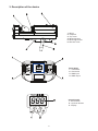
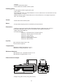
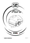
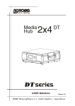
3. Description of the device
1 - Mirror
2 - Objective
3 - Top cover
4 - Mounting base
5 - Mounting bracket
6 - Bracket screw
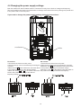
Front panel:
1 - Fuseholder
2 - Powercord
3 - DMX input
4 - DMX output
Control board:
1 - Enter-button
2 - Up,Down buttons
3 - Display
5
4. Installation
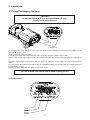
4.1Fitting/Exchanging the lamp
DANGER !
Install the lamps with the device switched off only.
Unplug from mains before !
Screw "A"
Screw "B"
To insert the lamp open the small cover at the rear panel (see the drawing) by loosening the 2 Phillips screws
"A" and "B" on the cover.
Gently pull out the lamp assembly.
If changing the lamp, remove the old lamp from the socket. Insert the lamp to the socket.
Do not install a lamp with a higher wattage! A lamp like this generates temperatures the device is not designed
for.
Damages caused by non-observance are not subject to warranty. Please follow the lamp manufacturer‘s
notes!
Do not touch the glass-bulb bare hands during the installation! Make sure that the lamp is installed tightly into
the lampholder system.
Reinsert the lamp assembly and tighten the 2 screws again.
Do not operate this fixture with opened housing-cover!
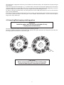
Lamp adjustment
6
The lampholder is aligned at the factory. Due to differences between lamps, fine adjustment may improve light
performance.
Strike the lamp and focus the light on a flat surface (wall). Center the hot-spot (the brightest part of the beam)
using the 3 adjustment screws "X, Y, Z". Turn one screw at a time to drag the hot-spot diagonally across the
projected image. If you cannot detect a hot-spot, adjust the lamp until the light is even.
To reduce a hot-spot, pull the lamp in by turning all three screws "X,Y, Z" clockwise 1⁄4-turn at a time until the
light is evenly distributed.
If the light is brighter around the edge than it is in the center, or if light output is low, the lamp is too far back in
the reflector. „Push” the lamp out by turning the screws "X,Y,Z" counterclockwise 1⁄4-turn at a time the light is
bright and evenly distributed.
4.2 Inserting/Exchanging rotating gobos
DANGER!
Instal the gobos with the device switched off only.
Unplug from mains before!
Remove the top cover of the scan by loosing the 4 fastening screws.
Remove the fixation-ring with an appropriate tool. Remove the gobo and insert the new gobo. Press the fixation-ring together and insert it in front of the gobo.
CAUTION!
Never unscrew the screws of the rotating gobo
as the ball bearing will otherwise be opened!
7
4.3 Rigging the fixture
The installation of the projector has to be built and constructed in a way that it can hold 10 times the weight for
1 hour without any harming deformation.
The installation must always be secured with a secondary safety attachment, e.g. an appropriate catch net.
This secondary safety attachment must be constructed in a way that no part of the installation can fall down if
the main attachment fails.
When rigging, derigging or servicing the fixture staying in the area below the installation place, on bridges,
under high working places and other endangered areas is forbidden.
The operator has to make sure that safety-relating and machine-technical installations are approved by an expert
before taking into operation for the first time and after changes before taking into operation another time.
The operator has to make sure that safety-relating and machine-technical installations are approved by an
expert after every four year in the course of an acceptance test.
The operator has to make sure that safety-relating and machine-technical installations are approved by a skilled
person once a year.
The projector should be installed outside areas where persons may walk by or be seated.
Important! Overhead rigging requires extensive experience, including (but not limited to) calculating working
load limits, installation material being used, and periodic safety inspection of all installation material and the
projector. If you lack these qualifications, do not attempt the installation yourself, but instead use a professional
structural rigger. Improper installation can result in bodily injury and.or damage to property.
The projector has to be installed out of the reach of people.
If the projector shall be lowered from the ceiling or high joists, professional trussing systems have to be used.
The projector must never be fixed swinging freely in the room.
Caution: Projectors may cause severe injuries when crashing down! If you have doubts concerning the safety
of a possible installation, do not install the projector!
Before rigging make sure that the installation area can hold a minimum point load of 10 times the projector’s
weight.
Danger of fire !
When installing the device, make sure there is no highly-inflammable
material (decoration articles, etc.) within a distance of min. 0.5 m.
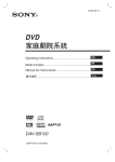
1.Mounting via mounting holes
Remove the scan bracket by unscrewing the 2 bracket screws.
Mount the clamp (not included) to the one of the two mounting holes in the mounting base. This mounting holes
have a diameter of 12 mm. Fix the scan via the clamp on a truss and tighten the rigging clamp.
For overhead use always install a safety rope that can hold at least 10 times the weight of the fixture. You must
only use safety rope with screw-on carabine. Pull the safety rope through the mounting base and over the
trussing system etc. Insert the end in the carabine and tighten the fixation screw.
safety rope
clamp
mounting holes
(diameter of 12 mm)
truss
8
2.Mounting via a mounting plate.
Mount the mounting plate (it si not standard part of delivery) on the wall using appropriate screws. The 4 mounting holes in the mounting plate have a diameter of 8 mm.Put the scan on the mounting plate and secure it with
the 2 bracket screws.
wall
mounting plate
bracket screw
3.Mounting via a mounting bracket.
Fix the scan bracket and tilt-fixation plate along the picture below.
Mount the clamp (not included) to the mounting bracket.The hole in the bracket has a diameter of 12mm. Fix
the scan via the clamp on a truss and adjust desired angle using tilt-lock screw.Retighten this screw.
For overhead use always install a safety rope that can hold at least 10 times the weight of the fixture. You must
only use safety rope with screw-on carabine. Pull the safety rope through the mounting base and over the
trussing system etc.
safety rope
mounting bracket
bracket screw
tilt-fixation plate
tilt-lock screw
bracket screw
clamp
tilt-lock screw
mounting holes
mounting bracket
truss
9
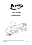
4.4 Changing the power supply settings
Both the transformer and the ballast must be connected correctly for the local AC voltage and frequency.
The wrong settings can cause poor performance or demage of the fixture.The factory settings are printed next
to the power cord on the front panel.
If you want to change the power supply settings,follow the instructions:
transformer
ballast
EU version:
1.Disconnect the fixture from AC power.
2.Remove the top cover of the fixtureby loosening the
4 screws.
3.Move the wire 1 on the transformer connection block
to the position according to the desired voltage.
4.Move the wires 2 and 3 on the ballast connection
block to the position according to the desired
frequency/voltage.
US version:
1.Disconnect the fixture from AC power.
2.Remove the front cover by loosening the 4 screws.
3.Move the wire 1 on the transformer connection block
to the position according to the desired voltage.
4.Move the wire 2 on the ballast connection block to
the position according to the desired frequency.
10
4.5 Connection to the mains
The earth has to be connected!
Connect the fixture to the mains with the enclosed power plug.
The occupation of the connection-cables is as follows:
Cable (EU)
Cable (US)
Pin
International
Brown
Black
Live
L
Light blue
White
Neutral
N
Yellow/Green
Green
Earth
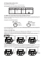
4.6 DMX-512 connection/connection between fixtures
The fixture is equipped with 3-pin XLR sockets for DMX input and output. Only use a shielded twisted-pair cable
designed for RS-485 and 3-pin XLR-plugs and connectors in order to connect the controller with the fixture or
one fixture with another.
Occupation of the XLR-connection:
DMX - output
DMX-input
XLR mounting-socket:
XLR mounting-plug:
1 - Ground
2 - Signal (-)
3 - Signal (+)
1 - Ground
2 - Signal (-)
3 - Signal (+)
If you are using standard controllers, you can connect the DMX-output of the controller directly with the DMXinput of the first fixture in the DMX-chain. If you wish to connect DMX-controllers with other XLR-outputs, you
need to use adapter-cables.
Building a serial DMX-chain:
Connect the DMX-output of the first fixture in the DMX-chain with the DMX-input of the next fixture. Always
connect one output with the input of the next fixture until all fixtures are connected.
Caution: At the last fixture, the DMX-cable has to be terminated with a terminator. Solder a 120 Ohm resistor
between Signal (–) and Signal (+) into a 3-pin XLR-plug and plug it in the DMX-output of the last fixture.
Building a master/slave-chain:
Connect the DMX-output of the master fixture in the data-chain with the DMX-input of the first slave. Always
connect output with the input of the next slave until all slaves are connected (up to 9 fixtures).
Caution:It’s necessary to insert the XLR termination plug (with 120 Ohm) into the input of the master fixture
and into the output of the last slave fixture in the link in order to ensure proper transmission on the data link.
11
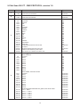
5.Club Scan 250 CT - DMX PROTOCOL ,version 1.0
Channel
Value
Function
Type of control
1
0-255
Pan
Control of the pan movement
proportional
2
0-255
Tilt
Control of the tilt movement
proportional
Colour wheel
Open/white
Turquoise
Red
Cyan
Light green
Magenta
Light blue
Yellow
Green
Pink
Blue
Orange
UV
Red/Blue
Yellow/Green
Blue/Purple
Forward rainbow effect from fast to slowt
No rotation
Backward rainbow effect from slow to fast
Random colour selection by audio control
Auto random colour selection from fast to slow
step
step
step
step
step
step
step
step
step
step
step
step
step
step
step
step
proportional
step
proportional
step
proportional
3
0-9
10-21
22-33
34-45
46-57
58-69
70-81
82-93
94-105
106-117
118-129
130-141
142-153
154-165
166-177
178-189
190-215
216-217
218-243
244-249
250-255
0-9
10-15
16-21
22-27
28-33
34-39
40-45
46-51
52-57
58-63
4
64-71
72-81
82-89
90-99
100-107
108-117
118-125
126-135
136-143
144-153
154-161
162-167
168-173
174-179
180-185
186-191
Rotating gobo wheel
Gobo selection
Open/hole
Gobo 1
Gobo 2
Gobo 3
Gobo 4
Gobo 5
Gobo 6
Gobo 7
Gobo 8
Gobo 9
Gobo shake, from slow to fast
Open/hole
Gobo 1
Gobo 2
Gobo 3
Gobo 4
Gobo 5
Gobo 6
Gobo 7
Gobo 8
Gobo 9
Pulse movement between two gobos ,from slow to fast
Hole --> Gobo 1
Gobo 1 --> Gobo 2
Gobo 2 --> Gobo 3
Gobo 3 --> Gobo 4
Gobo 4 --> Gobo 5
Gobo 5 --> Gobo 6
12
step
step
step
step
step
step
step
step
step
step
proportional
proportional
proportional
proportional
proportional
proportional
proportional
proportional
proportional
proportional
proportional
proportional
proportional
proportional
proportional
proportional
4
5
6
192-197
198-203
204-209
210-217
218-229
230-231
232-243
244-249
250-255
Gobo 6 --> Gobo 7
Gobo 7 --> Gobo 8
Gobo 8 --> Gobo 9
Gobo 9 --> Hole
Gobo wheel rotation from fast to slow (forward)
No rotation
Gobo wheel rotation from slow to fast (backward )
Random gobo selection by audio control
Auto random gobo selection from fast to slow
proportional
proportional
proportional
proportional
proportional
step
proportional
step
proportional
0-127
128-190
191-192
193-255
Gobo rotation
Gobo positioning
Forward gobo rotation from fast to slow
No rotation
Backward gobo rotation from slow to fast
proportional
proportiona
step
proportiona
0-5
6-85
86-95
96-127
128-139
140-191
192-223
224-255
Dimmer,strobe,program trigger
Closed
Dimmer from closed to open
Full open
Strobe-effect from slow to fast
Reset
Program time trigger (editable program runs by time control)
Program audio trigger (editable program runs by audio control)
Random Audio trigger (random effects run by audio control)
step
proportional
step
proportional
step
step
step
step
13
6. Controller mode
The fixtures are individually addressed on a data link and connected to the controller.The fixtures respond to
the DMX signal from the controller.
6.1 DMX addressing
The control panel on the front panel of the fixture allows you to assign the DMX fixture address, which is defined
as the first channel from which the ClubScan 250 will respond to the controller.
If you set, for example, the address to channel 7, the ClubScan 250 will use the channel 7 to 12 for control
.Please, be sure that you don’t have any overlapping channels in order to control each ClubScan 250 correctly
and independently from any other fixture on the DMX data link.
If two, three or more ClubScan 250 are addressed similarly, they will work similarly.
For address setting, please refer to the instructions under "Fixture address"(menu "001").
Note:After switching on, the ClubScan 250 will automatically detect whether DMX 512 data is received or not.If
there is no data received at the DMX-input, the display will start to flash "001" with actually set address.
This situation can occur if:
- the 3 PIN XLR plug (cable with DMX signal from controller) is not connected with the input of the ClubScan
250 - the controller is switched off or defective, the cable or connector is defective or the signal wires are swap
in the input connector.
Note:It’s necessary to insert the XLR termination plug (with 120 Ohm) to the last fixture in the link in order to
ensure proper transmission on the DMX data link.
14
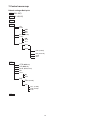
7.Control menu map
Default settings=Bold print
001 (001-507)
MI.S. (01..10..20)
tSt
St.A.
r.Pr.
St.M.
OFF
MSt
SLA
Aut (OFF,On)
C.S.A
tiM.
Au.P.
Au.r.
Pr.E.
E.01
:
E.30
SPE.
PAn (0-255)
:
tiM. (0-25.5s)
COP.
End
r.PA.(OFF,On)
r.til.(OFF,On)
PA.M. (PA.1,PA.2)
VEr.
UPd.
No
YES
Adj.
PAn (0-255)
:
CAL
CoL. (0-255)
Gob (0-255)
A.rE.
rES.
15
8. Functions of the control panel
The control panel situated on the front cover of the scan offers several features. You can simply set the DMX
address or master (slave) mode,switch On and Off the lamp,run a test,make a reset and also use other functions for setting fixture behaviour.
Control elements on the control board:
[ENTER] button- enters menu,confirms adjusted values and leaves menu.
,
[UP] button and[DOWN] button- moves between menu items on the the same level, sets values.
In order to leave the menu without saving value,press [UP] and [DOWN ] at the same time.
After switching the fixture on,the display shows the initial DMX address:
Use [UP],[DOWN] to browse through the menu. To select a function or submenu,press [ENTER].
8.1 Fixture Address
Use this menu to set the DMX address of the fixture which is defined as the first channel from which the fixture
will respond to the controller.
For address setting follow this procedure:
1. Switch On the fixture and wait until the fixture reset has finished ("rES" is flashing at the display).
2. Browse through the menu by pressing the [UP] and [DOWN] keys until the display shows current addres
"001".Confirm by pressing [ENTER] key and "001" will start to flash frequently.
3. Use the [UP] and [Down] keys to select the desired address.
4. Confirm by pressing [ENTER].
After having addressed fixtures, you may now start operating fixtures via your lighting controller.
8.2 Microphone sensitivity
Select this function to adjust the microphone sensitivity from 1(maximum) to 20(minimum).
8.3 Demo-test sequences
Use the item to run a built-in demo-test sequences without an external controller,which will show you some
possibilities of using the fixture.
8.4 Stand-alone setting
Select this menu to set fixture behaviour in stand-alone mode.
r.Pr. --- Running program.Select this menu to run a program in a loop.
St.M. --- Stand-alone mode.This function allows you to set the fixture as master or as slave:
OFF. --- The option disables Master/slave operation.
Mst --- Master. This function sets the fixture as a master.
SLA ---Slave. This function sets the fixture as a slave.
Aut. --- Automatically playback.This function allows you to play the program automatically after switching the
fixture on.The program will be played continuously in a loop.
16
C.S.A. --- Control of the stand-alone operation.
tIM. --- Time trigger. Select this item to run program by time control.
Au.P. --- Audio trigger program.Select this item to run program by audio control
Au.r. --- Audio/auto trigger random effect.Select this item to run random generated effects
by the audio control.If there are no audio impulses present,the fixture will generate random
effects.
Pr.E. --- Editing program.Select this menu to edit the program.The fixture has one editable program.Each
prog. step has a step time-the time,during which effects last in the current step.
Programming procedure:
1. Press [UP] or [DOWN] to select the desired program step ("E.01" - "E.30") and press [ENTER].
2. Press [UP] or [DOWN] to select the desired item and press [ENTER]-button.Now you can edit by [UP] or
[DOWN] buttons the DMX value (0-255) for selected item:
Pan
- pan movement,value 0-255
Tilt
- tilt movement,value 0-255
Col.
- colour wheel,value 0-255
Gob. - gobo wheel, value 0-255
G.ro. - gobo rotation, value 0-255
COPY - copying the current prog. step to the next prog. step.
tIM.
- step time,value 0-25.5 seconds
End. - this item stops the program.
Press [ENTER]-button to confirm adjusted value .
3.Select next prog. step and repeat this procedure (steps 1-3).
The number of steps in your program will be determined by the position in which you confirm the "End" for
the end of the program.If you want to extend the program, select "COP." in the last step to copy current step
to the next step.
8.5 Fixture reset
Select this item if you wish to make a fixture reset.
8.6 Special functions
Use this menu for special services like updating software or effect calibration.
r.PA. --- Pan reverse - This function allows you to invert the pan movement. Use the [ Up ] and [Down ] keys
to select “On” if you wish this feature or “Off” if you don’t wish this feature and press [ Enter ] to confirm and
return to the main menu.
r.til. --- Inverse tilt - This function allows you to invert the tilt movement. Use the [ Up ] and [Down ] keys to
select “On” if you wish this feature or “Off” if you don’t wish this feature and press [ Enter ] to confirm and
return to the main menu.
PA.M. --- Pan mode - This function allows you to set 2 ranges of the pan movement:144°-PA.2
187°-PA.1
VEr. --- Software version.Select this function to read the software version of the fixture processor.
UPd. --- Software update - Using this function you can update software in the fixture via PC and serial link.
The following are required in order to update software:
- PC running Windows 95/98/2000/XP or Linux
- DMX Software Uploader
- Flash cable RS 232/DMX (No.13050624)
Note1:Software update should execute a qualified person.If you lack qualification, do not attempt the update
yourself and ask for help your ROBE distributor.
Note 2:DMX address,program and all settings will be set to their default values
To update software in the fixture:
1.Installation of DMX Software Uploader:
17
1.DMX Software Uploader program is available from the ROBE web site at WWW.robe.cz.
2.Make a new directory ( e.g. Robe_Uploader) on your hard disk and download the software to it.
3.Unpack the program from the archive.Program file has name:DSU_name of corresponding
fixture_SoftwareID.If the Robe fixture is produced in magnetic and electronic ballast version, the
name of DMX Software Uploader is the same for both versions.
SoftwareID describes the versions of fixture software included in DMX Software Uploader. Higher
number means later software versions.
2.Fixture software updating:
1.Determine which of your COM port is available on your PC and connect it with to the DMX input
of the fixture using the Flash cable. Do not extend this cable! Disconnect the fixture from the
other fixtures in DMX chain! Turn on the computer and the fixture.
2.Switch the fixture to the update mode by selecting the option Software update in menu Special
Functions on the fixture control panel:SPE-->UPd-->yES.(From this option you cannot return back to
the main menu. If you do not want to continue in software update, you have to switch off and on the
fixture to leave this option!)
3.It is recommended that you exit all programs before running the Software Uploader.
4.Start the Software Uploader program. Select desired COM and then click Connect button.
If the conection is OK, click Start Uploading button to start uploading. It will take several minutes to
perform software update.All processors will be updated (including processors with the same
software version).
If you wish to update only later versions of processors, enable the Incremental Update check box.
Avoid interrupting the process. Update status is being displayed in the list window.
When the update is finished, the line with the text “The fixture is successfuly updated‘ will appear
in this window and the fixture will reset with the new software.
Note: In the case of interruption of the upload process (e.g. power cut), the fixture remains in the update mode
and you have to repeat the software update again.
For example: The fixture was switched off before finishing software upload. After switching the fixture on again,
the fixture is still in the update mode and the display is dark. Restart the Software Uploader program and repeat
software update from your PC.
CAL. --- Effect calibration.By this function you can calibrate and adjust the effects to their standard/right
positions.Disconect the DMX controller from the fixture and select "AdJ." menu.The display shows step by step
effects by which you can adjust the fixture to the required position before the function calibration(DMX controller
must be disconnected).When the positioning is finished ,select "CAL." and press [ENTER]:
1. Calibration via the control board
Disconnect DMX controller from the fixture.Press [ENTER] to display the following item: "Col.,Gob." for very
smooth function calibration. Select one of them and press [ENTER] and use the [UP] and [DOWN] in order
to adjust their right value from 0 to 255. After having calibrated all effects use the "A.rE." function in order to
write the calibration value to the memory (EEPROM) and to make a reset.
2. Calibration via the external controller
Connect the DMX controller to the fixture, press [ENTER] to display the following item: "Col,Gob".Select one of
them and press [ENTER] and now you can calibrate this effect by your controller. The DMX calibration protocol
is described below:
Effect
Channel
"Col."- Colour wheel
7
"Gob."- Gobo wheel
8
Afterhaving calibrated all effects press [ENTER] to confirm and than use the "A.rE." function in order to write
the calibration value to the memory (EEPROM) and to make a reset.
18
9. Stand - alone mode
The fixtures on a data link are not connected to the controller but can execute pre-set program which can be
different for every fixture."Stand-alone operation" can be applied to the single fixture (the fixture may be set
to the master or slave mode ) or to multiple fixtures operating synchronously.Effect actions are triggered by
sound,using built-in microphone, or automatically using an internal timer.
Synchronous operation of multiple fixtures requires that they must be connected on a data link and one of them
is set as a master ("MSt") and the rest as the slaves ("SLA").Up to 32 fixtures can be connected in master/slave
chain.Only one fixture can be set as the master.The slaves mimic the behavior of the master.
Important!:Disconect the fixtures from the DMX controller before master/slave operating ,otherwise data collisions can occur and the fixtures will not work properly!
Time control:
The master fixture starts simultaneous program start in the other slave fixtures.All fixtures have a definite, synchronized starting point when playing back their programs.Every fixture runs its program repeatedly ,starting
the program step No.1 when requested by the master .
For example:
If the slave fixture has a shorter program length, it will continously repeat its program until the master fixture
finishes its own program and restarts its program running (slave 1- prog.step 3 will not be finished).
If the slave fixture has a longer program length, it will restart at prog. step 1 before it completes all its
prog.steps
(slave 2 - prog.step 5 will not be played)- see the picture bellow.
Diagram 1
Audio control:
The sound beat starts program steps simultaneous in the master fixture and in the slave fixtures.Every fixture
runs its program repeatedly ,starting the program step when requested by the master.(Master is controlled by
sound and sends demand on the slaves to move them to the next prog.step).
Diagram 2
Operating multiple fixtures in stand-alone mode.
1.Select one fixture and set it as a master (Menu path: "St.A."--->"St.M."--->MSt).
2.The rest of the fixtures set as slaves (Menu path: "St.A."--->"St.M."--->SLA).
19
3.Build the master/slave chain.(See chapter DMX-512 connection and Master/Slave connection).
4.Activate automaticaly program running after switching the fixtures on(Menu path: "St.A."--->"Aut."--->On).
5.Set the program running options (Menu path: "St.A."--->"C.S.A.") on the master and slaves:
For time control of the fixtures select item "tiM" on the master and all slaves.
For audio control of the fixtures select item "Au.P." on the master and all slaves.
For audio random selection of effects ,select item "Au.r" on the master and all slaves
Note: Master-slave operation is only possible among fixtures: ClubScan 250,ClubScan 150,Fusion,
Funky and Trance.
10. Error and information messages
C.Er. (color-wheel error)
This messsage will appear after the reset of the fixture if the magnetic-indexing circuit malfunctions (sensor
failed or magnet missing) or the stepping-motor is defective (or its driver circuit on the main PCB). The colorwheel is not located in the default position after the reset.
G.Er. (rotating gobo-wheel error)
This message will appear after the reset of the fixture if the magnetic-indexing circuit malfunctions (sensor
failed or magnet missing) or the stepping-motor is defective (or its driver circuit on the main PCB). The rotating
gobo-wheel is not located in the default position after the reset.
M.Er.(Master error)
The message informs you that the fixture was addressed as a master and DMX signal is connected to its
input.Disconnect the DMX controller from the fixture's input and make the reset of the fixture.
11.Technical specifications
Power supply:
EU version
US version
-Voltage......................208,230 ,240V AC, 50/60Hz ~
-Fuse..........................T 3,15 A@ 230V
-Voltage......................100,120,208,230,240V AC, 50/60Hz ~
-Fuse..........................T 6,3 A@ 120V
-Power consumption.....300 VA
Lamp:
-Sylvania BA 250/2 SE
Optical System:
- High reflecting aluminium-coated parabolic reflector
- Manual focus
- 19° beam angle
Bampath:
Colours:
- 11 dichroic-filters plus white
20
- UV-filter
- 3 dichroic semicolours filters
- Colour-wheel with variable rotation speed
Rotating gobos:
- 5 metal gobos,4 dichroic gobos plus open
- Gobo rotation
- The metal gobos have an outside diameter of 16 mm ,thickness 0.5 mm,aluminium and an
image diameter of 13 mm.
- Multicolor dichroic gobo:outside diameter=15.8 mm,thickness=1.1mm,high temperature
borofloat or better glass
Strobe:
- Strobe effect with variable speed
Motor:
- 6 high quality stepping-motors controlled by microprocessors
Electronics:
- Intelligent control panel with 3-digit LED display allowing: addressing pan and tilt re
verse,effect calibration,reset of the unit and built-in demo sequences running
- Digital serial input DMX-512
- 6 control-channels:
Channel 1: Horizontal mirror-movement (Pan)
Channel 2: Vertical mirror-movement (Tilt)
Channel 3: Colour-wheel
Channel 4: Rotating gobos
Channel 5: Rotating gobo rotation
Channel 6: Shutter,strobe
Pan/Tilt:
Pan movement range 144°or 187°
Tilt movement range 58°
Temperatures:
-Maximum ambient temperature : 45° C
-Maximum housing temperature : 80° C
Minimum distances:
-Min.distance from flammable surfaces: 0.5 m
-Min.distance to lighted object: 1.0 m
Dimensions and weight:
- Weight:13 kg (EU version),16 kg (US version)
21
Optional acesories:
Flash cable RS232/DMX.......... No.13050624
Mounting plate CT.....................No.10980023
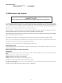
12. Maintenance and cleaning
DANGER TO LIFE!
Disconnect from mains before starting maintenance operation!
It is absolutely essential that the fixture is kept clean and that dust, dirt and smoke-fluid residues must not build
up on or within the fixture. Otherwise, the fixture‘s light-output will be significantly reduced. Regular cleaning will
not only ensure the maximum light-output, but will also allow the fixture to function reliably throughout its life.
Please use a moist, lint-free cloth. Never use alcohol or solvents!
The front mirror and objective lens will require weekly cleaning as smoke-fluid tends to building up residues,
reducing the light-output very quickly. The cooling-fan should be cleaned monthly.
The gobos may be cleaned with a soft brush. The interior of the fixture should be cleaned at least annually
using a vacuum-cleaner or an air-jet.
The dichroic colour filters, the rotating gobo wheel and the internal lenses should be cleaned monthly.
There are no serviceable parts inside the device except for the lamp and the fuse. Maintenance and service
operations are only to be carried out by authorized distributor.
Please refer to the instructions under „Fitting/Exchanging the lamp“.
Replacing the fuse
If the lamp burns out, the fine-wire fuse of the device might fuse too. Only replace the fuse by a fuse of the
same type and rating .
Before replacing the fuse, unplug mains lead!
Procedure:
Step 1: Unscrew the fuse holder on the front panel with a fitting screwdriver from the housing (anti-clockwise).
Step 2: Remove the old fuse from the fuseholder.
Step 3: Install the new fuse in the fuseholder.
Step 4: Replace the fuseholder in the housing and fix it.
Should you need any spare parts, please use genuine parts.
If the power supply cable of this device becomes damaged, it has to be replaced by authorized distributor only
in order to avoid hazards.
Should you have further questions, please contact our distributor.
22
23