1
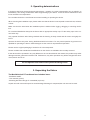
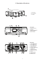
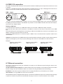
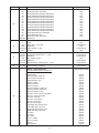
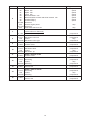
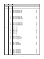
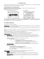
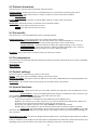
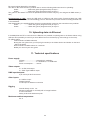
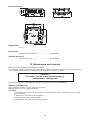
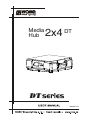
Media
Hub
2x4
DT
DT
Version 1.0
1
MediaHub 2x4 DT
Table of contents
1. Safety instructions ......................................................................................................... 3
2. Operating determinations.............................................................................................. 4
3. Unpacking the fixture..................................................................................................... 4
4. Description of the device............................................................................................... 5
5. Product Overiew ............................................................................................................. 6
6. Installation....................................................................................................................... 6
6.1 Mounting the fixture.................................................................................................... 6
6.2 Connection to the mains ............................................................................................ 7
6.3 Powering on the MediaHub 2x4 DT ........................................................................... 7
6.4 Shutting down the MediaHub 2x4 DT ........................................................................ 7
6.5 Folders organization................................................................................................... 7
6.7 Ethernet connection ................................................................................................... 8
6.6 DMX-512 connection.................................................................................................. 8
6.8 Configuring the MediaHub 2x4 DT.......................................................................... 10
7. MediaHub 2x4DT - DMX Protocol - version 1.0.......................................................... 11
8. Media Hub - Control menu map .................................................................................. 19
9. Control menu ............................................................................................................... 20
9.1 Fixture Address ....................................................................................................... 20
9.2 Fixture information ................................................................................................... 21
9.3 Personality ............................................................................................................... 21
9.4 Test sequences........................................................................................................ 21
9.5 Default settings ........................................................................................................ 21
9.6 Special functions ...................................................................................................... 21
10. Uploading data via Ethernet ...................................................................................... 22
11. Technical specifications ............................................................................................ 22
12. Maintenance and cleaning ........................................................................................ 23
2
CAUTION!
Keep this device away from rain and moisture!
Unplug mains lead before opening the housing!
FOR YOUR OWN SAFETY, PLEASE READ THIS USER MANUAL CAREFULLY
BEFORE YOU INITIAL START - UP!
1. Safety instructions
Every person involved with installation of this device has to:
- be suitable qualified and be familiar with this type of product
- follow the instructions of this manual
CAUTION!
Be careful with your operations.
With a high voltage you can suffer
a dangerous electric shock when touching the wires!
This device has left our premises in absolutely perfect condition. In order to maintain this condition and to ensure a safe operation, it is absolutely necessary for the user to follow the safety instructions and warning notes
written in this manual.
Important:
The manufacturer will not accept liability for any resulting damages caused by the non-observance of this
manual or any unauthorized modification to the device.
Please consider that damages caused by manual modifications to the device are not subject to warranty.
Make sure that the available voltage is not higher than stated on the User manual.
Always plug in the power plug least. Make sure that the power-switch is set to off-position before you connect
the device to the mains. The power plug has to be accessable after installing the device.
Make sure that the power-cord is never crimped or damaged by sharp edges. Check the device and the powercord from time to time.
Always disconnect from the mains, when the device is not in use or before cleaning it. Only handle the powercord by the plug. Never pull out the plug by tugging the power cord.
This device falls under protection class I.Therefore it is essential to connect the yellow/green conductor to
earth.
The electric connection, repairs and servicing must be carried out by a qualified employee.
3
2. Operating determinations
If the device has been exposed to drastic temperature fluctuation (e.g. after transportation), do not switch it on
immediately. The arising condensation water might damage your device. Leave the device switched off until
it has reached room temperature.
Do not shake the device. Avoid brute force when installing or operating the device.
When choosing the installation-spot, please make sure that the device is not exposed to extreme heat, moisture
or dust.
Make sure that the area below the installation place is blocked when rigging, derigging or servicing the fixture.
For overhead installation always fix the fixture with an appropriate safety rope. Fix the safety rope at the correct holes only.
Only operate the fixture after having checked that the housing is firmly closed and all screws are tightly fastened.
Operate the device only after having familiarized with its functions. Do not permit operation by persons not
qualified for operating the device. Most damages are the result of unprofessional operation!
Please use the original packaging if the device is to be transported.
Please consider that unauthorized modifications on the device are forbidden due to safety reasons!
If this device will be operated in any way different to the one described in this manual, the product may suffer
damages and the guarantee becomes void. Furthermore, any other operation may lead to dangers like shortcircuit,electric shock etc.
Do not operate this fixture with opened housing-cover!
3. Unpacking the fixture
The MediaHub 2x4 DT cardboard box includes items:
- MediaHub 2x4DT
- User manual (1piece)
- Mounting brackets Omega CL assembled (2 pieces)
Unpack unit with care and inspect for transit demage.If damage is suspected,the unit must not be used.
4
4. Description of the device
1 - Top cover
2 - Front panel
3 - Handle
MONITOR
Front panel
1 - Infra-red sensor
2 - Display
3 - RNS control wheel
4 - Escape button
5 - Enter button
ROBE
NAVIGATION
SYSTEM
ESC
ENTER
Rear panel
1 - 5-pin DMX output
2 - 5-pin DMX input
3 - 3-pin DMX output
4 - 3-pin DMX input
5 - RS-232 output
6 - 15-Pin VGA outputs
7 - USB inputs
8 - RGBHV outputs
9 - ATX power button
10 - Fuse
11 - Power switch
12 - Ethernet input
13 - Power cord
5
5. Product Overiew
MediaHub 2x4DT is a DMX controllable digital media server utilizes Windows XP and Direct X technology.MediaHub
2x4DT use DMX protocol to control loading images and movies.The graphic engine enables you manipulate
position,scale,rotation,apply vizual effects and colour mix each image.
Features:
System
MediaHub 2x4DT based on Windows XP Embedded and Direct X technology
DMX 512 and Art-Net support connection
RGBHV and VGA connection
Hardware
3 GHz Intel® LGA775 Pentium 4 Prescott processor
1GB RAM
Intel® Graphics Media Accelerator 915G
80 GB hard disc
Gigabit Ethernet card
2 USB ports,v.2.0
RS 232 Serial port
6. Installation
6.1 Mounting the fixture
Fixture suitable for dry locations only!
Do not expose this fixture to rain or moisture!
The fixture can be placed directly on the stage floor or rigged in any orientation on a truss without altering its
operation characteristics.
For overhead use, always install a safety-rope that can hold at least 10 times the weight of the fixture. You must
only use safety ropes with screw-on carabines. Pull the safety rope through the two apertures on the bottom of
the base and over the truss. Insert the end in the carabine and tighten the fixation screw.
Before rigging make sure that the installation area can hold a minimum point load of 10 times the fixture’s
weight.
When rigging, derigging or servicing the fixture staying in the area below the installation place, on bridges,
under high working places and other endangered areas is forbidden.
Avoid brute force when installing or operating the unit.
When choosing the installation-spot, please make sure that the unit is not exposed to extreme heat, moisture
or dust.
Only operate the unit after having checked that the housing is firmly closed and all screws are tightly fastened.
CAUTION!
Use 2 appropriate clamps to mount the fixture on the truss.
Follow the instructions mentioned at the bottom of the base.
Make sure that the device is fixed properly! Ensure that the
structure (truss) to which you are attaching the fixtures is secure.
Overhead fixation via the omega holders
1.Bolt each clamp (1) to the Omega holder (4) with M12 bolt and lock nut through the hole in the holder.
2.Fasten the Omega holders to the bottom of the fixture inserting both quick-lock fasteners (3) into the holes
of base and tighten fully clockwise.
3.Fasten the safety-rope (2) through the two apertures on the bottom of the fixture and around the truss.
6
1-Clamp
2-Safety-rope
3-Quick-lock fastener
4-Omega holder
6.2 Connection to the mains
Connect the fixture to the mains with the power cord.
If the plug on the flexible cord is not the right type for your socket outlets,do not use an adaptor,but remove the
plug from the cord and discard.Carefully prepare the end of the the supply cord and fit a suitable plug.
The earth has to be connected!
Cable (EU)
Cable (US)
Pin
International
Brown
Black
Live
L
Light blue
White
Neutral
N
Yellow/Green
Green
Earth
6.3 Powering on the MediaHub 2x4 DT
Connect the fixture to the power source.Switch on the Power switch on the rear side of the fixture
6.4 Shutting down the MediaHub 2x4 DT
A DMX controller can shut down the fixture remotaly with the shutdown option of the control channel No.6
Removing power directly without the shutdown procedure
can reduce fixture reliability!
When shutdown procedure is finished,switch off the Power switch on the rear side of the fixture.
6.5 Folders organization
The MediaHub 2x4 DT has a file system that holds the images and movies .These files are saved in 2 folders:
"gobo1"- images/movies for layer 1
"gobo2 "- images/movies for layer 2
The images and video clips can be in one of the following formats: .bmp;.jpg; .tga; .png; .mpg1; .mpg2.
The last folder is named "Update" and the new software has to be copy into it before software update.Its subfolder "backup" contains old software version.
All the above-mentioned folders are shared.
7
6.6 DMX-512 connection
The fixture is equipped with both 3-pin and 5-pin XLR sockets for DMX input and output.The sockets are wired
in parallel.
Only use a shielded twisted-pair cable designed for RS-485 and 3-pin or 5-pin XLR-plugs and connectors in
order to connect the controller with the fixture or one fixture with another.
DMX - output
DMX-input
XLR mounting-sockets (rear view):
1 - Shield
2 - Signal (-)
3 - Signal (+)
4 - Not connected
5 - Not connected
XLR mounting-plugs (rear view):
1 - Shield
2 - Signal (-)
3 - Signal (+)
4 - Not connected
5 - Not connected
If you are using the standard DMX controllers, you can connect the DMX output of the controller directly with
the DMX input of the first fixture in the DMX link. If you wish to connect DMX controllers with other XLR-outputs,
you need to use adapter cables.
Building a DMX link.
1.Connect the XLR connector of a DMX data cable to the controller´s DMX data output connector.
2.Connect the data cable´s XLR connector to the DMX In connector of the first (or next) fixture on the DMX
link.
3.Continue linking the remaining fixtures connecting a cable from the DMX Out connector of each fixture to the
DMX In connector of the next fixture on the link.
4.Set desired DMX addresses on all fixtures.Option “ DMX In” has to be selected from “Operation mode” menu
on all fixtures.
Caution: At the last fixture, the DMX link has to be terminated with a terminator. Solder a 120 Ω resistor between
Signal (–) and Signal (+) into a 3-pin (5-pin) XLR plug and connect it to the DMX Out of the last fixture.
Example:
Operation mode: DMX In
DMX address=73
Operation mode: DMX In
DMX address=37
Operation mode: DMX In
DMX address=1
6.7 Ethernet connection
The fixtures communicates with your workstation or laptop over an Ethernet network using the Art-net communication protocol.
Art-Net communication protocol is a 10 Base T Ethernet protocol based on the TCP/IP.Its purpose is to allow
transfer of large amounts of DMX 512 data over a wide area using standard network technology.
IP address is the Internet protocol address.The IP uniquely identifies any node (fixture) on a network.
The Universe is a single DMX 512 frame of 512 channels.
The MediaHub 2x4 DT is equipped with 8-pin RJ- 45 socket for the Ethernet input.Use a network cable category
5 (with four “twisted” wire pairs) and standard RJ-45 plugs in order to connect the fixture to the network.
8
RJ-45 socket (front view):
RJ-45 plug (front view):
1- TD +
2- TD 3- RX +
4- Not connected
5- Not connected
6- RX 7- Not connected
8- Not connected
Patch cables that connect fixtures to the hubs or LAN sockets are wired 1:1,that is,pins with the same numbers
are connected together:
1-1
2-2
3-3
4-4
5-5
6-6
7-7
8-8
If only the fixture and the computer(or two fixtures) are to be interconnected,no hubs or other active components
are needed.A cross-cable has to be used:
1-3
2-6
3-1
4-8
5-7
6-2
7-5
8-4
Building an Ethernet link
1.Connect the network cable´s connector to the Ethernet Hub output.
2.Connect the network cable´s connector to to the Ethernet input (RJ-45)of the first fixture on the Ethernet
link.
3.Continue linking the remaining fixtures connecting a cable from the Ethernet input of each fixture to the outputs of the Ethernet Hub.
4.Set desired DMX and IP addresses and Universe on all fixtures.Option “ Artnet In” has to be selected from
“Operation mode” menu on all fixtures.
Example:
Operation mode: Artnet In
DMX address=73
IP addres=002.168.002.004
Universe=0 1
Operation mode: Artnet In
DMX address=1
IP addres=002.168.002.003
Universe=0 1
Operation mode: Artnet In
DMX address=1
IP addres=002.168.002.002
Universe=0 2
Art-Net
Art-Net
Art-Net
Ethernet
Hub
Computer
Building a DMX/Ethernet link
1.Connect the XLR connector of a DMX data cable to the controller´s DMX data output connector.
2.Connect the data cable´s XLR connector to the DMX In connector of the first fixture on the DMX/Ethernet
link.
3.Connect the network data cable from the first fixture´s Ethernet input to the Ethernet Hub Input of.
4.Continue linking the remaining fixtures connecting a network cables from the Ethernet input connector of each
fixture to the output connectors of the Ethernet Hub.
5.Set desired DMX address on the first fixture and from menu “Operation mode” select “ DMX In-Artnet Out”
6.Set suitable DMX and IP addresses and universe on the rest of the fixtures.Option “ Artnet In” has to be
selected from “Operation mode” menu on these fixtures.
Example:
9
Operation mode: Artnet In
DMX address=37
IP addres=002.168.002.004
Universe= 0 1
Operation mode: Artnet In
DMX address=1
IP addres=002.168.002.003
Universe=0 1
Operation mode: DMX In-Artnet Out
DMX address=1
IP addres=002.168.002.002
Universe=0 1
6.8 Configuring the MediaHub 2x4 DT
Before controlling the fixture from a DMX controller or PC,you need to:
1.Define the source of DMX data (see chapter "Fixture address",Operation mode).
2.Set IP address and another values related to the Ethernet operation if it is needed (see chapter "Fixture
address",Ethernet settings)
3.Assign a valid DMX start channel (see chapter "Fixture Address,DMX address).
10
7. MediaHub 2x4DT - DMX Protocol - version 1.0
Channel
Value
Function
Type of control
Gobo layer 1
1
2
0 - 255
Dimmer 1
Dimmer intensity from 0% to 100%
0
1
2
3
4
5
6
7
8
9
10
11
12
13
14
15
16
17
18
19
20
21
22
23
24
25
26
27
28
29
30
31
32
33
34
35
36
37
38
39
40
41
42
43
44
45
46
Gobo 1 selection
White
Gobo 1-black and white
Gobo 2-black and white
Gobo 3-black and white
Gobo 4-black and white
Gobo 5-black and white
Gobo 6-black and white
Gobo 7-black and white
Gobo 8-black and white
Gobo 9-black and white
Gobo 10-black and white
Gobo 11-black and white
Gobo 12-black and white
Gobo 13-black and white
Gobo 14-black and white
Gobo 15-black and white
Gobo 16-black and white
Gobo 17-black and white
Gobo 18-black and white
Gobo 19-black and white
Gobo 20-black and white
Gobo 21-colour
Gobo 22-colour
Gobo 23-colour
Gobo 24-colour
Gobo 25-colour
Gobo 26-black and white
Gobo 27-colour
Gobo 28-black and white
Gobo 29-black and white
Gobo 30-colour
Gobo 31-colour
Gobo 32-colour
Gobo 33-black and white
Gobo 34-from yellow to green
Gobo 35-from red to yellow
Gobo 36-from magenta to red
Gobo 37-from blue to magenta
Gobo 38-from cyan to blue
Gobo 39-from light green to cyan
Gobo 40-RGB strips
Gobo 41-colour animation
Gobo 42-colour animation
Gobo 43-colour animation
Gobo 44-colour animation
Gobo 45-colour animation
Gobo 46-colour animation
47
48
49
50
51
52
Gobo 47-colour animation
Gobo 48-colour animation
Gobo 49-colour animation
Gobo 50-colour animation
Gobo 51-colour animation
Gobo 52-colour animation
proportional
step
step
step
step
step
step
step
step
step
step
step
step
step
step
step
step
step
step
step
step
step
step
step
step
step
step
step
step
step
step
step
step
step
step
step
step
step
step
step
step
step
step
step
step
step
step
step
step
step
step
step
step
step
11
Channel
Value
Function
2
53
54
55
56
57
58
59
60
61
62
63
64
65
66
67
68-255
Gobo 53-colour animation
Gobo 54-colour animation
Gobo 55-black and white animation
Gobo 56-black and white animation
Gobo 57-black and white animation
Gobo 58-black and white animation
Gobo 59-black and white animation
Gobo 60-black and white animation
Gobo 61-black and white animation
Gobo 62-black and white animation
Gobo 63-black and white animation
Gobo 64-black and white animation
Gobo 65-Robe logo animation
Gobo 66-Robe logo
Gobo 67-colour animation
Reserved
0
1-127
128
129-254
255
Gobo 1 control
Stop
Play slow---> normal
Play loop
Play normal---> fast
Pause
step
proportional
step
proportional
step
0 -63
64-127
128
129-192
193-255
Gobo 1 Indexing and rotation
Clockwise rotation fast ---> slow
Indexing
No rotation-centre
Indexing
Anticlockwise rotation slow ---> fast
proportional
proportional
step
proportional
proportional
0 - 255
Gobo 1 fine indexing (rotation)
Fine indexing (rotation)
proportional
3
4
5
6
0
1
2
3
4
5
6
7
8
9
10
11
12
13
14
15
16
17
18
19
20
21
22
23
24
25
26
27
Gobo 1 effect Selection
(set amount/speed on channel 7)
Disabled
Zoom sinus
Zoom bump in fade out
Zoom fade in bump out
Zoom bump in out
Zoom in fade
Zoom out fade
Scale xy sinus
Scale xy bump in fade out
Scale xy fade in bump out
Scale xy bump in out
XY pos. circle counter-clockwise
XY pos. circle clockwise
XY pos. scroll up
XY pos. scroll down
XY pos. scroll left
XY pos.scroll right
Left-right diag. down scroll
Left-right diag. up scroll
Right-left diag. down scroll
Right-left diag. up scroll
X rotate
Y rotate
XY rotate
XY inv. rotate
X inv. y rotate
Tile xy
Tile xy sinus
12
Type of control
step
step
step
step
step
step
step
step
step
step
step
step
step
step
step
Type of effect control
speed
speed
speed
speed
speed
speed
speed
speed
speed
speed
speed
speed
speed
speed
speed
speed
speed
speed
speed
speed
speed
speed
speed
speed
speed
amount
speed
Channel
Value
Function
6
28
29
30
31
32
33
34
35
36
37
38
39
40
41
42
43
44
45
46
47
48
49
50
51
52
53
54
55
56
57
58
59
60
61
62
63
64
65
66
67
68
69
70
71
72
73
74
75
76
XYZ rot. cube
XYZ rot. sphere
X rot. cylinder
Y rot. cylinder
Cone z scale sinus
Kaleidoscope
Fisheye in
Fisheye out
Swirl left
Swirl right
Bend x
Bend y
Tile frame
Frame
Plane flip x
Plane flip y
Plane flip x y
Plane mirror x
Plane mirror y
Plane mirror xy
Plane tile 2x
Plane tile 3x
Plane tile 4x
Plane tile 5x
Disc
Disc flip x
Disc flip y
Disc flip x y
Disc mirror x
Disc mirror y
Disc mirror xy
Squeeze in
Squeeze out
Plane wavy diag 1
Plane wavy diag 2
Stretch x
Stretch y
Colour to black and white
Colour to black and white inv.
Black and white to black and white inv.
Inverted
Black Mask
Black Mask inverted
Contrast
Brightness
RGB to GBR
RGB to BRG
RGB to RBG
Black and white to black and white inverted and timed
speed
speed
speed
speed
speed
none
none
none
none
none
none
none
none
none
none
none
none
none
none
none
none
none
none
none
none
none
none
none
none
none
none
none
none
none
none
none
none
amount
amount
amount
amount
amount
amount
amount
amount
amount
amount
amount
speed
77
78
79
80
81
82
Colour to black and white timed
Colour to inverted timed
Cycle
Cycle inverted
Sepia
Sepia inverted
speed
speed
speed
speed
amount
amount
83
84
85
86
87
88
Colour Key
Colour Key inverted
Key Black
Key Black inverted
Key White
Key White inverted
amount
amount
amount
amount
amount
amount
13
Type of effect control
Channel
Value
6
89
90
91
92
93
94
95
96
97-249
250
251-254
255
White flash
Black flash
Alpha flash
Invert flash
Black and white flash
Black and white to black and white inverted flash
Gradient Wipe x
Gradient Wipe y
Reserved
Render engine pause
Reserved
Shut down=255 for 5 sec.
0 - 255
Gobo 1 effect control
(Select effect on channel 6 )
Control of amount/speed
proportional
0-127
128
129-255
Gobo 1 Position X coarse
Movement to the left
Centre
Movement to the right
proportional
step
proportional
Gobo 1 position X fine
Position X fine
proportional
Gobo 1 Position Y coarse
Movement down
Centre
Movement up
proportional
step
proportional
0-255
Gobo 1 position Y fine
Position Y fine
proportional
0-127
128
129-255
Gobo 1 zoom X coarse
Narrowing
Centre
Widening
proportional
step
proportional
Gobo 1 zoom X fine
Zoom X fine
proportional
Gobo 1 zoom Y coarse
Narrowing
Centre
Widening
proportional
step
proportional
Gobo 1 zoom Y fine
Zoom Y fine
proportional
7
8
9
10
11
12
13
14
15
0-255
0-127
128
129-255
0-255
0-127
128
129-255
0-255
Function
14
Type of control
speed
speed
speed
speed
speed
speed
speed
speed
step
step
Channel
Value
Function
Type of control
Gobo layer 2
Dimmer 2
Dimmer intensity from 0% to 100%
16
17
proportional
0
1
2
3
4
5
6
7
8
9
10
11
12
13
14
15
16
17
18
19
20
21
22
23
24
25
26
27
28
29
30
31
32
33
34
35
36
37
38
39
40
41
42
43
44
45
46
Gobo 2 selection
White
Gobo 1-black and white mask
Gobo 2-black and white mask
Gobo 3-black and white mask
Gobo 4-black and white mask
Gobo 5-black and white mask
Gobo 6-black and whitemask
Gobo 7-black and white mask
Gobo 8-black and white mask
Gobo 9-black and white mask
Gobo 10-black and white mask
Gobo 11-black and white mask
Gobo 12-black and white mask
Gobo 13-black and white mask
Gobo 14-black and white mask
Gobo 15-black and white mask
Gobo 16-black and white mask
Gobo 17-black and white mask
Gobo 18-black and white mask
Gobo 19-black and white mask
Gobo 20-black and white mask
Gobo 21-colour
Gobo 22-colour
Gobo 23-colour
Gobo 24-colour
Gobo 25-colour
Gobo 26-gray
Gobo 27-colour
Gobo 28-gray
Gobo 29-gray
Gobo 30-colour
Gobo 31-colour
Gobo 32-colour
Gobo 33-black and white
Gobo 34-from yellow to green
Gobo 35-from red to yellow
Gobo 36-from magenta to red
Gobo 37-from blue to magenta
Gobo 38-from cyan to blue
Gobo 39-from green to cyan
Gobo 40-RGB strips
Gobo 41-colour animation
Gobo 42-colour animation
Gobo 43-colour animation
Gobo 44-colour animation
Gobo 45-colour animation
Gobo 46-colour animation
step
step
step
step
step
step
step
step
step
step
step
step
step
step
step
step
step
step
step
step
step
step
step
step
step
step
step
step
step
step
step
step
step
step
step
step
step
step
step
step
step
step
step
step
step
step
step
47
48
49
50
51
52
53
Gobo 47-colour animation
Gobo 48-colour animation
Gobo 49-colour animation
Gobo 50-colour animation
Gobo 51-colour animation
Gobo 52-colour animation
Gobo 53-colour animation
step
step
step
step
step
step
step
15
Channel
Value
Function
17
54
55
56
57
58
59
60
61
62
63
64
65
66
67-255
Gobo 54-colour animation
Gobo 55-black and white animation
Gobo 56-black and white animation
Gobo 57-black and white animation
Gobo 58-black and white animation
Gobo 59-black and white animation
Gobo 60-black and white animation
Gobo 61-black and white animation
Gobo 62-black and white animation
Gobo 63-black and white animation
Gobo 64-black and white animation
Gobo 65-Robe logo animation
Gobo 66-Robe logo
Reserved
0
1-127
128
129-254
255
Gobo 2 control
Stop
Play slow---> normal
Play loop
Play normal---> fast
Pause
step
proportional
step
proportional
step
0 -63
64-127
128
129-192
193-255
Gobo 2 Indexing and rotation
Clockwise rotation fast ---> slow
Indexing
No rotation-centre
Indexing
Anticlockwise rotation slow ---> fast
proportional
proportional
step
proportional
proportional
0 - 255
Gobo 2 fine indexing (rotation)
Fine indexing (rotation)
proportional
18
19
20
21
0
1
2
3
4
5
6
7
8
9
10
11
12
13
14
15
16
17
18
19
20
21
22
23
24
25
26
27
28
29
Gobo 2 effect Selection
(set amount/speed on channel 22)
Disabled
Zoom sinus
Zoom bump in fade out
Zoom fade in bump out
Zoom bump in out
Zoom in fade
Zoom out fade
Scale xy sinus
Scale xy bump in fade out
Scale xy fade in bump out
Scale xy bump in out
XY pos.circle ccw
XY pos. circle cw
XY pos. scroll up
XY pos. scroll down
XY pos. scroll left
XY pos.scroll right
Left-right diag. down scroll
Left-right diag. up scroll
Right-left diag. down scroll
Right-left diag up scroll
X rotate
Y rotate
XY rotate
XY inv. rotate
X inv. y rotate
Tile xy
Tile xy sinus
XYZ rot. cube
XYZ rot. sphere
16
Type of control
step
step
step
step
step
step
step
step
step
step
step
step
step
Type of effect control
speed
speed
speed
speed
speed
speed
speed
speed
speed
speed
speed
speed
speed
speed
speed
speed
speed
speed
speed
speed
speed
speed
speed
speed
speed
amount
speed
speed
speed
Channel
Value
Function
21
30
31
32
33
34
35
36
37
38
39
40
41
42
43
44
45
46
47
48
49
50
51
52
53
54
55
56
57
58
59
60
61
62
63
64
65
66
67
68
69
70
71
72
73
74
75
76
77
78
79
80
81
82
83
X rot. cylinder
Y rot. cylinder
Cone z scale sinus
Kaleidoscope
Fisheye in
Fisheye out
Swirl left
Swirl right
Bend x
Bend y
Tile frame
Frame
Plane Flip x
Plane Flip y
Plane Fip x y
Plane mirror x
Plane mirror y
Plane mirror xy
Plane tile 2x
Plane tile 3x
Plane tile 4x
Plane tile 5x
Disc
Disc Flip x
Disc Flip y
Disc Flip x y
Disc mirror x
Disc mirror y
Disc mirror xy
Squeeze in
Squeeze out
Plane wavy diag 1
Plane wavy diag 2
Stretch x
Stretch y
Colour to black and white
Colour to black and white inverted
Black to white inverted
Inverted
Black Mask
Black Mask inverted
Contrast
Brightness
RGB to GBR
RGB to BRG
RGB to RBG
Black and white to black and white inverted timed
Colour to black and white timed
Colour to inverted timed
Cycle
Cycle inverted
Sepia
Sepia inverted
Colour Key
speed
speed
speed
none
none
none
none
none
none
none
none
none
none
none
none
none
none
none
none
none
none
none
none
none
none
none
none
none
none
none
none
none
none
none
none
amount
amount
amount
amount
amount
amount
amount
amount
amount
amount
amount
speed
speed
speed
speed
speed
amount
amount
amount
84
85
86
87
88
89
90
Colour Key inverted
Key Black
Key Black inverted
Key White
Key White inverted
White Flash
Black Flash
amount
amount
amount
amount
amount
speed
speed
17
Type of effect control
Channel
Value
21
91
92
93
94
95
96
97-255
Alpha Flash
Invert Flash
Black and white Flash
Black and white to black and white inverted Flash
Gradient Wipe x
Gradient Wipe y
Reserved
0-255
Gobo 2 effect control
(Select effect on channel 21)
Control of amount/speed
proportional
0-127
128
129-255
Gobo 2 Position X coarse
Movement to the left
Centre
Movement to the right
proportional
step
proportional
Gobo 2 position X fine
Position X fine
proportional
Gobo 2 position Y coarse
Movement down
Centre
Movement up
proportional
step
proportional
0-255
Gobo 2 position Y fine
Position Y fine
proportional
0-127
128
129-255
Gobo 2 zoom X coarse
Narrowing
Centre
Widening
proportional
step
proportional
Gobo 2 zoom X fine
Zoom X fine
proportional
Gobo 2 zoom Y coarse
Narrowing
Centre
Widening
proportional
step
proportional
Gobo 2 zoom Y fine
Zoom Y fine
proportional
22
23
24
25
26
27
28
29
30
0-255
0-127
128
129-255
0-255
0-127
128
129-255
0-255
Function
Type of control
speed
speed
speed
speed
speed
speed
Common channels for both gobo layers
31
32
33
34
35
36
0-255
Cyan
Cyan (0-white, 255-full cyan)
proportional
0-255
Magenta
Magenta (0-white, 255-full magenta)
proportional
0-255
Yellow
Yellow (0-white, 255-full yellow)
proportional
0
1-254
255
Iris
Open iris
From max.diameter to min.diameter
Closed iris
step
proportional
step
0-255
Iris fine
Iris fine
proportional
Strobe
Open light output
Strobe-effect from slow to fast
Open light output
Random strobe-effect from slow to fast
Open light output
step
proportional
step
proportional
step
0 - 30
31 - 80
81 - 110
111 - 140
141 - 255
l
18
8. Media Hub - Control menu map
Default settings=Bold print
Default settings=Bold print
Fixture Address
DMX Address
001
:
512
Ethernet Settings
Set IP Address
Set ArtNet Universe
Operation mode
DMX in
Artnet in
DMX in-Artnet out
Fixture Information
DMX values
Channel (1-36)
DMX value (0-255)
Software version
Render Engine
Display Device
Product IDs
Folder Size
Gobo 1
Gobo 2
Personality
Display Adjusting
Display Permanent On (On,Off)
Display intensity (1...10...15)
Display Backlight (1...5...10)
Display Turned (On,Off)
IR sensor (On,Off)
Test sequences
Demo mode 1
Demo mode 2
Default settings
Display
Ethernet and DMX
Media Folder
Special functions
Updating software
From Hardrive
From USB
Upload data from USB
Download data to USB
19
9. Control menu
The control panel situated on the front panel of the base offers several features. You can simply set the DMX
address and use many functions for setting fixture behaviour.
Control elements on the control board:
[RNS] encoder wheel-moves between menu items on the the same level, scrolls between values.
[ESC] button-leaves menu without saving changes
[ENTER] button-selects and stores entries.
After switching the fixture on,
Press [ENTER],
the display shows the initial screen:
the display shows current address:
The main menu of the control panel is accessed by pressing [ENTER] button. To browse through the menu,
rotate [RNS] wheel. To select a function or submenu, press [ENTER] button. The curently selected options will
be highlighted.The menu items are described below.
9.1 Fixture Address
Use this menu to set the DMX address.
DMX Address - Select this submenu to set DMX start address.Use RNS wheel to enter a valid DMX start
channel and confirm it by pressing [ENTER].
DMX start address is defined as the first channel from which the MediaHub 2x4 DT will respond to the controller.
If you set, for example, the address to channel 37, the MediaHub 2x4 DT will use the channel 37 to 73 for
control.
Please, be sure that you don’t have any overlapping channels in order to control each MediaHub 2x4 DT correctly and independently from any other fixture on the DMX data link.
If two, three or more MediaHub 2x4 DT are addressed similarly, they will work similarly.
Ethernet Settings - Select this submenu to set the fixture for Ethernet operating.
Set IP Address - Select this item to set IP address.IP address is the Internet Protocol address.
The IP uniquely identifies any node (fixture) on a network. There can't be 2 fixtures with the same IP
address on the network!The format of an IP address is a 32-bit numeric address written as four
numbers separated by periods. Each number can be zero to 255.
To set the IP address:
1. Select „Set IP Address” and press [ENTER].
2. Use RNS wheel to set the first number of IP addres.
3. Press [ENTER] to move on the second number of IP address.
4. Repeat steps 2 and 3 for the second,third and fourth number of IP
address and confirm it by pressing [ENTER] .
Set ArtNet Universe - Select this item to set a Universe. The Universe is a single DMX 512 frame
of 512 channels.
To set the Art-net universe:
1. Select „Set Artnet universe” and press [ENTER].
2. Use RNS wheel to set the Subnet value.
3. Press [ENTER] to move on the ID and set valid value and confirm
by pressing [ENTER].
Operation mode - This menu item defines the source of DMX data and has three options:
DMX In - Data is transmited over standard DMX cables.
Artnet In - Data is transmitted over Ethernet cables using the Art-net protocol (see chapter
Ether net connection).
DMX in-Artnet out - Data is transmited over standard DMX cable to the first fixture and from this
fixture data is transmited over Ethernet cables using the Art-net protocol (see chapter Ethernet
connection).
20
9.2 Fixture information
Use this menu to read an useful information about the fixture.
Channel Values - Select this function to read DMX values of each channel received by the fixture.
Software Version - Select this function to read the software version of the fixture modules:
Render Engine
Display Device
Product IDs - Select this function to read the MAC address or fixture code of the fixture.
Folder Size - Select this function to read the size of particular folders:
Gobo 1-The gobos and movies for layer 1
Gobo 2-The gobos and movies for layer 2
9.3 Personality
Use this menu to to modify MediaHub 2x4 DT operating behavior.
Display Adjusting - This function allows you to change the display settings.
Display Permanent On - This function allows you to keep the display on or to turn off
automatically 2 minutes after last pressing any button on the control panel.
Display Intensity - Select this function to adjust the display intensity (1-min.,15-max.).
Display Backlight - Select this function to adjust the display backlight (1-min.,10-max.).
Display Turned - Select this function to turn the display by 180°.
IR Sensor - Select this function to switch on/off infra-red remote control.
9.4 Test sequences
Use this menu to to run demo sequences without an external controller, which will show you some possibilities
of using the fixture.
Demo mode 1
Demo mode 2
9.5 Default settings
Select this option to upload factory values for the fixture:
Display - This option returns all display setting to the factory values.
Ethernet and DMX - This option returns IP address,Art-net values ,DMX address and Operating Mode to the
factory values.
Media folder - This option restores factory gobos in the folders Gobo1 and Gobo2.
9.6 Special functions
Updating software - Using this function you can update software via USB stick or PC and Ethernet connection.
From Hardrive - Connect the MediaHub 2x4 DT (directly or via Ethernet Hub ) to the PC.If you
connect MediaHub 2x4 DT directly with PC ,cross-cable has to be used.
To update software in the MediaHub 2x4 DT:
1.The current software is available from the ROBE web site at WWW.robe.cz.
2.Make a new directory (e.g. Robe_Software) on your PC hard disk and download the software to it.
3.Unpack the program from the archive.Program file has name dt.exe.
4.Copy the new software (dt.exe) to the folder update in the Media Hub 2x4 DT.
5.Select option "From Hardrive" in the the menu and wait until the software update is finished.
From USB - The new software (file dt.exe) has to be saved in the folder update on the USB
stick.Insert the USB stick to USB port and select option "From USB".Confirm your selection and updating process will start.i
Upload data from USB - The fixture is equipped with 2 USB ports for connecting an external memory medium
(e.g.USB stick).
Insert the USB stick to the USB port and select option "Upload data from USB card".Confirm this selection and
uploading process will start.This process will last according the data size to be transfered.
21
Be careful,original data will be overwriten.
The data on the external memory medium has to use the following folders structure for uploading:
Gobo1
........folder with gobos (images/movies) for layer 1
Gobo2
........folder with gobos (images/movies) for layer 2
The gobos in the folders are sorted in alphabetical order and this way they are assigned to DMX values (1255).
Download data to USB - Insert the USB stick to USB port and select option "Download data from USB
card".Confirm your selection and downloading process will start.This process will last according the data size
to be transfered.
After downloading ,the standard folder structure is automatically created on the external memory medium:
Gobo1
........ folder with gobos (images/movies) for layer 1
Gobo2
........ folder with gobos (images/movies) for layer 2
10. Uploading data via Ethernet
If the MediaHub 2x4 DT is connected to the Ethernet,it is possible to upload gobos to the fixture without using
USB port.This possibility is useful if you have difficult acces to the fixture(e.g. fixture hangs on the truss).
To update gobos:
1.Set channel 6 at DMX value 250
2.Copy the new gobos from your PC(or light console) to the folders Gobo1 and Gobo2 on the hard
disk of the fixture
3.Set channel 6 at DMX value 0 for a moment
4.Now you can use your new gobos
11. Technical specifications
Power supply:
Voltage:...........................100-240V AC, 50/60Hz ~
Fuse:...............................T 1.6A@230V, T 3.15A@120V
Power consumption:........130 VA
Video outputs:
2 x 15-Pin VGA output
2 x BNC Type RGBHV output
DMX inputs/outputs:
3-pin and 5-pin XLR connectors
Other inputs:
2 x USB 2.0 input
RS232 interface
RJ-45 input for Ethernet connection
Rigging
Stands directly on the floor
Mounts horizontally or vertically with 2 Omega brackets
2 truss orientation
Safety chain/cord attachment point
Maximum ambient temperature:
30° C
22
Dimensions(mm):
Weight (net):
9.5 kg
Accessories
Omega holders (2 pieces)...............................No.99010420
Optional acesories:
Remote control IR............................................No.13050419
12. Maintenance and cleaning
There are no user servicable parts within the product.
It is absolutely essential that the fixture is kept clean A soft lint-free cloth moistened with any good cleaning
fluid is recommended, under no circumstances should alcohol or solvents be used!
DANGER !
Disconnect from the mains before starting any
maintenance or cleaning work
Maintenance and service operations are only to be carried out by authorized distributors.
Replacing the main fuse
Only replace the fuse by a fuse of same type and rating.
Before replacing the fuse, unplug mains lead.
Procedure:
1) Unscrew the fuseholder on the rear panel of the base with a fitting screwdriver from the housing
(anti - clockwise).
2) Remove the old fuse from the fuseholder.
3) Install the new fuse in the fuseholder.
4) Replace the fuseholder in the housing and fix it.
23
24