1
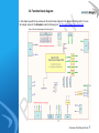
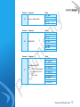
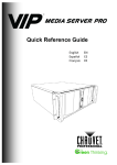
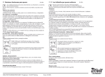
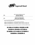
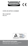
User Guide Meerkat K1 Bring-Up Kit Product information Avionic Design GmbH | Wragekamp 10 | 22397 Hamburg | Germany Fon +49 -40 - 88 187-0 | [email protected] www.avionic-design.de Product: Meerkat K1 Bring-Up Kit Product number: 1477-000-000 Manufacturer: Avionic Design GmbH Wragekamp 10 22397 Hamburg Germany In cooperation with: NVIDIA® Revision history Document number 1477-001-315 Date July 2015 Version 00 Remarks Preliminary release Copyright All the rights to this user guide provided through this service revert to Avionic Design GmbH. Any and all reproduction, modification, or publication of the guides and/or manuals either in part or their entirety without the permission of Avionic Design GmbH is prohibited under copyright laws. NVIDIA, the NVIDIA logo and Tegra are trademarks and/or registered trademarks of NVIDIA Corporation. Other company and product names may be trademarks of the respective companies with which they are associated. The Meerkat products are subject to change. Please check www.avionic-design.de for updates. Table of contents List of illustrations ............................................................................................................................................................................................ 4 1. Introduction.............................................................................................................................................................................................. 5 2. Technical properties ................................................................................................................................................................................. 6 3. Overview of the Bring-Up Carrier ............................................................................................................................................................. 7 3.1 Structure of the Bring-Up Carrier ................................................................................................................................................... 7 3.2 Function block diagram 9 3.3 Main components of the Bring-Up Kit ......................................................................................................................................... 10 3.4 Pinouts of the connectors on the Bring-Up Carrier ..................................................................................................................... 11 4. First steps ............................................................................................................................................................................................... 18 4.1 Unpack the Meerkat K1 Bring-Up Kit ........................................................................................................................................... 18 4.2 Turn on the Bring-Up Kit .............................................................................................................................................................. 19 4.3 Get access to the shell of the Bring-Up Kit................................................................................................................................... 24 5. 4.3.1 Get access through the Debug Serial/RS232 port ..................................................................... 24 4.3.2 Get access through SSH/Ethernet ............................................................................................. 26 Boot concept .......................................................................................................................................................................................... 27 5.1 Boot loader 27 5.2 Bootstrap the system 28 5.2.1 Activate recovery mode............................................................................................................. 28 5.2.2 Flash the bootloader.................................................................................................................. 29 5.2.3 Rebuilding and customization the kernel and root filesystem .................................................. 29 Contact ........................................................................................................................................................................................................... 30 List of illustrations Figure 1: Top view of the Bring-Up Carrier Figure 2: Function block diagram for the Bring-Up Kit Figure 3: Packaged TEC-NG and its components Figure 4: Get access to the Bring Up Kit through these ports Figure 5: Turn on the TEC with these components Explanation of the symbols Indicates a list of various items Indicates the result of a step Indicates additional information Indicates hyperlinked chapters and sections within the user guide Abridged list of abbreviations SOM Bring-Up Kit BUC TBD System on a Module, here: Meerkat K1 Processor Module Meerkat K1 Bring-Up Kit Meerkat K1 Bring-Up Carrier To be defined //List of illustrations 4 1. Introduction Meerkat - Let’s innovate together! Meerkat is a platform by Avionic Design that features NVIDIA’s Tegra® technology. Meerkat defines the form factor, the pinout and the function set. The Meerkat Bring-Up Kit consists of two core components: the Meerkat Tegra® K1 Processor Module (SOM) and the Meerkat Tegra K1 Bring-Up Carrier (BUC). The BUC is a bring up reference platform and you can use it as a basis for development. It carries the Meerkat Tegra K1 Processor Module, which features the NVIDIA® Tegra® K1 processor. The BUC will help you evaluate some of functions that the Meerkat K1 Processor Module has to offer. User guide This user guide will enable you to use the BUC. It will introduce all the relevant functions of the Meerkat Bring-Up Kit. and the required software for it. This document will give you an overview of the BUC, its main components and the board connectors. It will show you how to start the BUC and how to use it properly in combination with the Meerkat K1 Processor Module. This guide will show you how to use the pre-installed software or, if required, bootstrap the Bring-Up Kit. Note Please read all the information in this user guide carefully! For more information on the Meerkat K1 Processor Module, please read the Meerkat K1 User Manual. You can find it at ftp://ftp.avionicdesign.de/pub/meerkat/ If you have any questions about this user guide, please contact Avionic Design. Introduction 5 2. Technical properties The lists below outline the main technical properties of the Meerkat K1 Bring-Up Carrier. General Size Supply voltage CPU name Cooling Interfaces 108 mm x 150 mm 12 V nominal NVIDIA® Tegra® K1 Heatsink with Fan Options CSI DSI/CSI Connector not assembled* Connector not assembled SATA HDMI USB 3.0 USB 2.0 client RS232 DSI various USER I/O Amount 1x 1x 1x 1x 1x 1x 1x Notes configurable as host Display, 4 Lanes - /Technical properties 6 3. Overview of the Bring-Up Carrier The following chapter will give you an overview of the Meerkat K1 Bring-Up Carrier and it will explain its main components. 3.1 Structure of the Bring-Up Carrier Figure 1: Top view of the Bring-Up Carrier /Overview of the Bring-Up Carrier 7 The explanation of Figure 1: Number 1 2 3 4 5 6 7 8 9 10 11 12 13 14 15 16 17 18 19 20 21 Component DC power jack (12 V) DC power connector (12V) Configuration pins DSI A SATA Debug UART Configuration pin USB3 Recovery / Bootstrap USB CSI Port Recovery button Connector 1 for CSI A Connector 2 for CSI A Connector 1 for CSI/DSI B Connector 1 for CSI/DSI B HDMI (Type C) General purpose pins Fan connector SATA power Reset button Power button Connector X18 X1 S4-S6 X22 X16 X7 X21 X25 X9 X12 S3 X20 X13 X8 X14 X19 X11 X23 X17 S2 S1 /Overview of the Bring-Up Carrier 8 3.2 Function block diagram In this chapter you will find an overview of the function block diagram for the Meerkat K1 Bring-Up Kit. You can find a larger version of this Schematic under the following Link: ftp://ftp.avionic-design.de/pub/meerkat/ Figure 2: Function block diagram for the Bring-Up Kit /Overview of the Bring-Up Carrier 9 3.3 Main components of the Bring-Up Kit The Meerkat K1 Bring-Up Kit consists of the following main components: Meerkat K1 Processor Module: NVIDIA® Tegra™ K13 SoC (see Meerkat K1 User Manual at: ftp://ftp.avionic-design.de/pub/meerkat/) Meerkat K1 Bring-Up Carrier: The Meerkat K1 Processor Module needs to be plugged into the carrier on the Dual channel opto-isolator Motorola: MOCD217 /Overview of the Bring-Up Carrier 10 3.4 Pinouts of the connectors on the Bring-Up Carrier In this chapter you will find a list of the pinouts of the connectors of the Meerkat K1 Bring-Up Carrier. Connector X1 Connector X8 Connector X14 Component DC power connector (JST - B2P- VH) (8 to 17V Input) Component MIPI Port 1: DSI/CSI B 4 Lanes Connector I Component MIPI Port 1: DSI/CSI B 4 Lanes Connector II Pinout Pin 1: Power Pin 2: GND Pinout Pin 1: GND Pin 2: DSI B D3 N Pin 3: DSI B D3 P Pin 4: GND Pin 5: GND Pin 6: DSI B CLK N Pin 7: DSI B CLK P Pin 8: GND Pin 9: GND Pin 10: DSI B D0 N Pin 11: DSI B D0 P Pin 12: GND Pinout Pin 1: GND Pin 2: DSI B D2 N Pin 3: DSI B D2 P Pin 4: GND Pin 5: GND Pin 6: DSI B D1 N Pin 7: DSI B D1 P Pin 8: GND /Overview of the Bring-Up Carrier 11 Connector X2 Connector X23 Connector X11 Component Recovery / Bootstrap USB Component DEBUG UART Component General Purpose GPIOs Note: - Pin 1 to 10: Level depends on Jumper X21 (1,8V or 3,3V) - Pin 11 and 12 Pinout Pin 1: VBUS Pin 2: DPin 3: D+ Pin 4: ID Pin 5: GND Pinout Pin 1: not connected Pin 2: TX Pin 3: RX Pin 4: not connected Pin 5: GND Pin 6: not connected Pin 7: open Pin 8: open Pin 9: not connected Pinout Pin 1: GND Pin 2: GPIO PH5 Pin 3: GPIO PI7 Pin 4: GPIO PK1 Pin 5: GPIO PO4 Pin 6: GPIO PO3 Pin 7: GPIO PP1 Pin 8: GPIO PO2 Pin 9: GPIO PO1 Pin 10: GND Pin 11: GPIO PW2 Pin 12: GPIO PX7 /Overview of the Bring-Up Carrier 12 Connector X12 Connector X20 Component CSI 2 Lanes Note: - Shared with X20. - Default X20 Component MIPI Port 0: CSI A 4 Lanes Connector I Pinout Pin 1: GND Pin 2: CSI A D0 Ext N Pin 3: CSI A D0 Ext N Pin 4: GND Pin 5: CSI A D1 Ext N Pin 6: CSI A D1 Ext N Pin 7: GND Pin 8: CSI A CLK Ext N Pin 9: CSI A CLK Ext N Pin 10: GND Pin 11: GPIO PH4 Pin 12: GPIO PH2 Pin 13: GEN I2C SCL Pin 14: GEN I2C SDA Pin 15: +3,3V Ext Pinout Pin 1: GND Pin 2: CSI B D1 N Pin 3: CSI B D1 P Pin 4: GND Pin 5: GND Pin 6: CSI A CLK MIPI N Pin 7: CSI A CLK MIPI P Pin 8: GND Pin 9: GND Pin 10: CSI A D0 MIPI N Pin 11: CSI A D0 MIPI P Pin 12: GND /Overview of the Bring-Up Carrier 13 Connector X13 Connector X16 Component MIPI Port 0: CSI A 4 Lanes Connector II Component Standard SATA Connector Component X17 SATA power Connector Component X18 Power Jack (8-17V Input) Pinout Pin 1: GND Pin 2: CSI B D0 N Pin 3: CSI B D0 P Pin 4: GND Pin 5: GND Pin 6: CSI A D1 MIPI N Pin 7: CSI A D1 MIPI P Pin 8: GND Pinout Pin 1: GND Pin 2: A+ Pin 3: APin 4: GND Pin 5: BPin 6: B+ Pin 7: GND Pinout Pin 1: Vcc (8-17V) Pin 2: GND Pin 3: GND Pin 4: +5 V Pinout Pin 1: Power Pin 2: GND /Overview of the Bring-Up Carrier 14 Connector X19 Component Standard HDMI (Type C) Pinout Pin 1: TDMS D2 SHIELD Pin 2: TDMS D2+ Pin 3: TDMS D2Pin 4: TDMS D1 SHIELD Pin 5: TDMS D1+ Pin 6: TDMS D1Pin 7: TDMS D0 SHIELD Pin 8: TDMS D0+ Pin 9: TDMS D0Pin 10: CLK SHIELD Pin 11: CLK+ Pin 12: CLKPin 13: DDC/CEC/HEC GND Pin 14: CEC Pin 15: I2C SCL Pin 16: I2C SDA Pin 17: HEC DATAPin 18: +5 V Pin 19: HEC DATA+ Connector X21 Component Voltage Jumper Pinout Pin 1: 1,8V Pin 2: Bank Power Pin 3: 3,3V /Overview of the Bring-Up Carrier 15 Connector X22 Component DSI Display (DSI port A) Pinout Pin 1: +3,3V Pin 2: +3,3V Pin 3: not connected Pin 4: LCD EN Pin 5: PWM Pin 6: I2C SDA Pin 7: I2C SCL Pin 8: not connected Pin 9: GND Pin 10: DSI A D2 P Pin 11: DSI A D2 N Pin 12: GND Pin 13: DSI A D1 P Pin 14: DSI A D1 N Pin 15: GND Pin 16: DSI A CLK P Pin 17: DSI A CLK N Pin 18: GND Pin 19: DSI A D0 P Pin 20: DSI A D0 N Pin 21: GND Pin 22: DSI A D3 P Pin 23: DSI A D3 N Pin 24: GND Pin 25: GND Pin 26: GND Pin 27: GND Pin 28: not connected Pin 29: not connected Pin 30: not connected Pin 31: +3.3 V Pin 32: +3.3 V Pin 33: +3.3 V Pin 34: +3.3 V /Overview of the Bring-Up Carrier 16 Connector X23 Connector X25 Component Fan Component USB 3 Pinout Pin 1: not connected Pin 2: FAN TACH Pin 3: +12V Pin 4: GND Pinout Pin 1: VCC Pin 2: DPin 3: D+ Pin 4: GND Pin 5: SSRXPin 6: SSRX+ Pin 7: GND Pin 8: SSTXPin 9: SSTX+ /Overview of the Bring-Up Carrier 17 4. First steps This chapter will show you how to start the Meerkat K1 Bring-Up Kit and enable you to work with it. 4.1 Unpack the Meerkat K1 Bring-Up Kit The TEC-NG and its components are individually packaged to deliver them safely (see Figure 3). Figure 3: Packaged TEC-NG and its components Explanation: 1. Bring-Up Kit 2. Small parts 3. Info flyer 1. Carefully unpack each component. 2. Compare the delivered components with the list in Chapter Fehler! Verweisquelle konnte nicht gefunden werden.. /First steps 18 Please contact Avionic Design, if a component is missing. /First steps 19 4.2 Turn on the Bring-Up Kit This chapter describes how to connect all the peripherals with the Bring-Up Kit and how to turn on the BringUp Kit. 1. Before you turn on the Bring-Up Kit, connect all the peripherals with the Bring-Up Kit USB Hub 1x HDMI cable (Type A to Type C) 1x RS232 null modem cable 1x Ethernet cable Optional items: 1x computer with a terminal emulator USB Hub with Type A plug 1x keyboard with a USB Type A plug 1x mouse with a USB Type A plug 1x USB 3 to Ethernet Adapter (e.g. Edimax EU-4208) 1x HD monitor with HDMI port (Type A) or alternatively to an HD monitor: 2.1 2.2 2.3 Put the USB Hub into the USB ports of the Bring Up Kit (see Figure 4). Put the USB plugs of the mouse, keyboard and USB-Ethernet Adapter into the USB Hub. Put one plug of the Ethernet cable into your local Ethernet network (with a DHCP server already setup) and put the other plug into the USB-Ethernet Adapterport of the Bring-Up Kit. /First steps 20 Figure 4: Get access to the Bring Up Kit through these ports Explanation: 1. USB Recovery 2. USB port 3. Debug UART port 4. HDMI port 2.4 Put one plug of the HDMI cable into an HD monitor and put the other plug into the HDMI port of the Bring-Up Kit (see Figure 4). Alternatively you can connect the Bring-Up Kit to a DSI display. 2.5 Put one plug of the RS232 null modem cable into the serial port of the computer and put the other plug into the Debug Serial/RS232 port of the Bring-Up Kit (see Figure 4). /First steps 21 3. After you connected the peripherals with the Bring-Up Kit, prepare these provided items to turn on the Bring Up Kit: 1x 12 V power supply (DC power supply (12V, 3 A). Jack Type PJ-063AH. (Inner contact +) 3.1 Put the plug of the 12 V power supply into a power outlet and put the power connector into the DC 3.2 power jack of the Bring Up Kit (see Figure 5): If your power outlet does not match the plug of the power supply, attach a plug adapter to the plug. The Bring-Up Kit has a power supply but the Bring-Up Kit is not turned on. The fan is running. Figure 5: Turn on the TEC with these components Explanation: 1. DC power connector 2. DC power jack /First steps 22 Figure 6: Turn on the Bring-Up Kit with these components 4. Explanation: 1. Recovery button 2. Reset button 3. Power button Push the power / reset button (see Figure 5) for approx. 1 second. The TEC-NG is on. Caution The NVIDIA® Tegra™ K1 SoC as well as other components are running hot, when the Meerkat products are turned on. To prevent burns, please do not touch the NIVIDA® Tegra™ K SoC and other components. /First steps 23 When the Bring-Up Kit is on, you can get access to the Bring-Up Kit in two different ways: You can get access to the shell of the Bring-Up Kit through the Debug Serial/RS232 port (see Chapter 4.3.1) You can get remote access to the shell of the Bring-Up Kit through SSH/ the Ethernet port (see Chapter 4.3.2) /First steps 24 4.3 Get access to the shell of the Bring-Up Kit After you turned the Bring-Up Kit on, you can get access to the shell of the Bring-Up Kit through either: the Debug Serial/RS232 port (see Chapter 4.3.1) or SSH/Ethernet (see Chapter 4.3.2) 4.3.1 Get access through the Debug Serial/RS232 port 1. Make sure that you connected the Bring-Up Kit and a computer with the provided RS232 cable and that the Bring-Up Kit is turned on (see Chapter 4.2). 2. Open the terminal emulator on the computer. Note Examples for terminal emulators are Minicom™ for Linux OS or Tera Term™ for Windows OS. 3. Set up your terminal emulator with the following parameters: Baud rate: 115200 Data length: 8 Parity: none Stop bit: 1 Flow control: none When you press the power button (see Figure 5), the boot-up process will start. You should see various kernel messages during the boot-up process. When the boot-up process is complete, you will see a login prompt. /First steps 25 4. Log in with the following parameters: Username: root Password: password The Linux shell opens after the login. A hashtag (#) prefixes each line and shows that you have root permissions. Note Be careful, when you have root access! You can permanently damage the system and make it inoperable! /First steps 26 4.3.2 Get access through SSH/Ethernet The Bring-Up Kit has no Ethernet interface. Ethernet can be used with an USB to Ethernet Adapter (e.g. Edimax EU-4208). 1. Make sure that you connected the Bring-Up Kit with the adapter to your local Ethernet network with an Ethernet cable (see Chapter 4.2). 2. To connect to the Bring-Up Kit via SSH, you need to determine the IP address of the system. 2.1 Read the instructions in Chapter 4.3.1 to get access to the Linux shell of the TEC-NG. 2.2 Write the command ifconfig into the Linux shell You will receive the IP address of the Bring-Up Kit. Note The actual IP address depends on the settings of the DHCP server. 2.3 To connect to the Bring-Up Kit via SSH using the IP address, write the command: $ ssh root@<ip address> /First steps 27 5. Boot concept This chapter will outline the boot concept of the Meerkat K1 Processor Module. The eMMC of the Meerkat K1 Processor Module contains a pre-installed GNU/Linux operating system. 5.1 Boot loader The eMMC is preflashed with a boot-loader called U-Boot™. It is a universal boot-loader and it supports various computer architectures. It loads the kernel. /Boot concept 28 5.2 Bootstrap the system The bootstrapping process puts the system into a defined bootable condition. The pre-installed operating system on the SOM is GNU/Linux system based on buildroot. You can bootstrap the SOM and rebuild your own system based on Linux. This invoves two steps: 1. Building and flashing the bootloader. 2. Building and flashing the kernel and root filesystem. 5.2.1 Activate recovery mode Before you activate the recovery mode of the Bring-Up Kit, make sure you have all the necessary items: Your delivery includes this item: 1x USB Mini-B to USB Type A cable Your delivery does not include this necessary item: 1x computer with a Linux OS 1. Put the USB Mini-B plug into the recovery USB port (see Figure 1) and put the USB Type A plug into a USB port on your computer. 2. The Module must be powered on 3. Push and hold the recovery button (see Figure 5) 4. Push the reset button to reset on the BUK. 5. Release the recovery button. The recovery mode is activated. /Boot concept 29 5.2.2 Flash the bootloader Here for you need to be in recovery mode.The procedure to Flash Uboot onto the target is described in the “software” section of the Meerkat User Manual which can be found under the following link ftp://ftp.avionic-design.de/pub/meerkat/ 5.2.3 Rebuilding and customization the kernel and root filesystem The source code for the preflashed operation system is published on git hub. It can be found under the following link: https://github.com/avionic-design/buildroot-external-ad/ There can be found a README which includes detailed instructions how to build the kernel and root file system and erlaubt die customization like adding and removing software packages. /Boot concept 30 Contact If you have any questions about the Meerkat K1 Bring-Up Kit, you can contact us at: Avionic Design GmbH Wragekamp 10 22397 Hamburg Germany www.avionic-design.com [email protected] Fon: +49 - 40 - 88 187 0 Contact 31