1
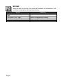
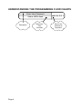
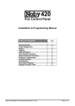
P3 SIM 3004 & 3004-IN INSTALLATION & USER MANUAL SAFETY NOTES Please read this manual carefully before attempting to install, program or operate the Progeny access control equipment. This equipment must be installed in line with all relevant regulations and standards. Make sure that wiring is rated according to fuses and current limits of relevant power supplies. Apart from the mains supply all connections to this unit must be SELV level. (Safety Extra Low Voltage, BS EN 60950 1992) No users should access inside the control box. The control box contains hazardous voltages and access is limited to qualified personnel only. All user programming for the controller is either done at one of the keyboards or at the PC. Every effort is made to ensure that this manual is complete and free from errors. However we reserve the right to make changes to these products and this manual without notice. No liability is accepted for loss damage or injury as a consequence of using these products or instructions. Website: www.progeny.co.uk Document Number: MAN0005 Date: Issue: Firmware Version Number: 27-03-2012 03 1.04 EMC & W WEEE Certificate Number WEE/JG2915VS Copyright BSB Electronics Ltd 2012 All rights reserved. 1. INTRODUCTION ________________________________________ 1 SOUND ________________________________________________________ 2 2. PROGRAMMING ________________________________________ 3 UNDERSTANDING THE PROGRAMMING FLOW CHARTS ______________ 4 3. USER MENU ______________________________________________ 5 SETTING DATE-TIME ____________________________________________ 6 SETTING THE DAY OF WEEK _____________________________________ 7 3. ENGINEERS MENU _____________________________________ 9 ENGINEERS PASSWORD ________________________________________ 10 RESET USER PASSWORD _______________________________________ 11 RESET USER PASSWORD _______________________________________ 12 RESTORING FACTORY SETTINGS ________________________________ 12 RESTORING FACTORY SETTINGS ________________________________ 13 4. INSTALLATION ________________________________________ 14 MOUNTING ____________________________________________________ 14 POWER_______________________________________________________ 14 Hardware System Diagram _______________________________________ 16 SPECIFICATION _______________________________________________ 19 Quick Reference _______________________________________________ 20 Commissioning Information______________________________________ 20 1. INTRODUCTION This Manual is for the Progeny P3 IO Controller, product code 3004 and 3004-IN. The 3004 controller has 16 inputs and 16 outputs, and the 3004-IN has 16 inputs only and is not supplied with a PSU. The built in charger-power supply for the 3004 is rated at 5A 12V DC . The P3 IO Controller is designed to be part of an online system centrally programmed via the Doors Enterprise software. Each controller has a real time clock and non-volatile event memory to allow for the system to continue operation even when isolated from the PC or remainder of the network. The controllers can connect via the interface lead direct to a COM Port on a PC. PRODUCT CODE 3004 3004-IN DESCRIPTION P3 Input Output Controller P3 Input Only Controller Page 1 SOUND Sound is used to give the user additional feedback on the status of the controller and progress during programming. Sound Four Notes “Low – High – Low – High” Two Notes “Low – High” Two Notes “High – Low “ Single Short Note “High” Page 2 Meaning Programming Mode Confirm Programming Change Programming Error Keyboard Key Push 2. PROGRAMMING UNLOCKING THE KEYBOARD To enable the keyboard for programming first press * and #. The keyboard will not accept any input until it is enabled. PROGRAMMING Programming is achieved by entering a password at the keyboard followed by a menu selection code. There are two programming menu’s, one for the USER and one for the ENGINEER. Each menu has a separate six-digit password. Depending on the menu option selected, configuration data can then be entered at the keyboard. The 3004 SIM unit contains a PSU with a programming keypad and one SIM unit. Therefore, the indicators for Control B are not used. Before programming, make sure that the ‘SELECTED’ indicator for Control A is illuminated. If not press [#] and [1] keys together. The controller will beep and the ‘Control ‘A’ selected’ LED will illuminate. Page 3 UNDERSTANDING THE PROGRAMMING FLOW CHARTS Enter User Password Status LED's flash Description Page 4 Responce from controller 654321 Keys to be pressed at keyboard 3. USER MENU The menu functions available and default factory settings are as follows: Users Menu # * 00 * 03 * 08 * 09 Description User Password Day of Week Set Date Set Time Default Settings 654321 - Page 5 U08 SETTING DATE-TIME U09 The internal clock of the P3 Controller has three main parameters: st 1. Date (010100 = 1 of January 2000) 2. Time (153001 = 3:30:01 pm) Enter current User Password Status LED's flash 654321 Select Menu 08 "Set Date" 8 Enter date in 6 digit format "ddMMyy" 010800 Finish Status LED's stop flashing Engineers function 09 allow the time to be set. Allways set the time using 24Hr format. Enter current User Password Status LED's flash Select Menu 09 "Set Time" 09 Enter time in 6 digit format "hhmmss" 105500 Finish Status LED's stop flashing Page 6 654321 U3 SETTING THE DAY OF WEEK The day of week is only important for the daylight savings feature to work correctly. This is because the date rule also uses the day of week to determine when to change the time. The set the day of week use the Day of Week table below to find the day ID and enter this as a value using the following procedure. Enter Password Status LED's flash 654321 Select Menu 3 "Set Day of Week" 03 Enter new value (1 to 7) 2 (Monday) Finish Status LED's stop flashing DAY OF WEEK IDENTIFIERS DAY OF WEEK SUNDAY MONDAY TUESDAY WEDNESDAY THURSDAY FRIDAY SATURDAY ID 1 2 3 4 5 6 7 Page 7 U00 USER PASSWORD Passwords are the means by which the systems operator gains access to the programming functions. This is a 6-digit number and can be changed by using the following procedure. Changing the user password Enter current User Password Status LED's flash Select Menu 00 "User Password" 00 Enter new 6 digit password 987654 Enter new 6 digit password again 987654 Finish Status LED's stop flashing Page 8 654321 3. ENGINEERS MENU The menu functions available and default factory settings are as follows: ENGINEERS MENU # DESCRIPTION DEFAULT SETTINGS * 00 * 29 * 99 Password Network Transmit Delay Reset Default User Password 123456 0 - Page 9 E00 ENGINEERS PASSWORD The passwords are the means by which the systems operator gains access to the programming functions. This is a 6-digit number and can be changed by using the following procedure. Changing the Engineers Password Enter current Engineer Password Status LED's flash Select Menu 00 "Engineer Password" 00 Enter new 6 digit password 007654 Enter new 6 digit password again 007654 Finish Status LED's stop flashing Page 10 123456 E29 NETWORK TRANSMIT DELAY The Network Transmit Delay is used to allow the controller to interface with USB to RS485 converters. The value entered will delay the controller from transmitting an RS 485 network response for 10ms x the value entered. Programming the Network Transmit Delay Enter current Engineer Password Status LED's flash 123456 Select Menu 29 "Network TX Delay" 29 Enter new value 0 to 99 ( x 10 ms) 2 Finish Status LED's stop flashing Page 11 E99 RESET USER PASSWORD It can be useful for the engineer to reset the user password. By entering the engineering menu and select function 99 the Users Password will be reset to the default “654321” Resetting the Users Password Enter current Engineer Password Status LED's flash 123456 99 Select Menu 99 "Reset User Password" Finish Status LED's stop flashing Page 12 RESTORING FACTORY SETTINGS Should you require to "reset the controller" at any time or in the event of the Programming code or being forgotten the factory settings may be restored. To do this push and hold down the push button located in the corner of the control PCB located within the enclosure. Hold this for 5 to 6 seconds. Wait for the RX and TX RS232 LED’s to flash. The Controller will now use the factory settings for all codes and timings. Page 13 4. INSTALLATION MOUNTING The optimum location for the controller depends on the application. As a general Guide: Always mount the control equipment on the secure side of the door. If the user needs to programme the unit from the keyboard on the front panel, mount at head height in an accessible location with reasonable light. Offer the opened back of the enclosure up to the wall where the unit is to be mounted and mark the location of the fixing dimples on the wall. Drill and plug the wall. Bring in mains supply and other cables that are to enter via the rear cable access holes. Screw the controller to the wall. WARNING: Extreme caution must be used when opening the controller housing. DO NOT touch any connections or components other than the reset button. Avoid touching any of the terminations with a metal object such as a wristwatch or jewellery. POWER The P3 IO Controller should be connected to a 24 Hour 220/240V mains supply. Ideally a fused spur should be used for this purpose. The cable used to connect the 2 mains supply should be 0.75 to 2mm . A fused terminal block is provided for mains, observe the polarity when making these connections. 3004 PSU POWER SUPPLY LOADS (MAXIMUM) The loads on the PSU terminals are as follows: Connection Current Limit with Resettable PSU Terminal Type Fuse Battery Spade Terminal 1A Charger Control A Grey Cable 2A Control B Grey Cable 2A OP A Terminal Block 1A OP B Terminal Block 1A Aux Terminal Block 2A Voltage 13.8V 13.8V 13.8V 13.8V 13.8V 13.8V There are overload LED indicators next to each terminal connection on the PSU. BUDGETTING Note that the above table shows the current limit of each connection and does not show the total budget available. Total available current at any one time is 5A. Page 14 When budgeting for the load it is the Peak current values of the devices that will be connected that should be used. IMPORTANT: If rechargeable batteries are to be fitted then they must be of the correct type. The power supply is designed to charge sealed lead acid batteries. Do not connect NiCad or Dry Cell batteries. Power up sequence should be: Mains first then Battery Power down sequence should be: Battery first then Mains Page 15 Hardware System Diagram Page 16 NETWORK CONNECTIONS The network used to link the controllers back to a central point is “RS 485”. This allows half duplex communication and requires a special cable type (Belden 8133, 8132 or equivalent). The 8133 has three twisted pairs the 8132 has two pairs with an overall screen and drain wire. When pulling the cable into place, be careful to avoid Fluorescent lighting ballast's and large mains transformers, motors and switchgear. When terminating strip back the cable sufficiently to identify the twisted pairs of cores. A B RX RX RX RX A B IMPORTANT PLEASE NOTE It is important to use the colour coding and keep the twisted pairs for connections as shown above. At each door controller the incoming and outgoing screens should be connected together. Connect the drain wires to the chassis earth stud at the first controller only. It is also important the network be one daisy chain with no spurs or loops. It is important that the Connection of the PC Interface Lead is correct as miss connection can damage the Controller. You will find an arrow on the cable connector, this indicates PIN 1. PIN 1 is also indicated on the controller PCB adjacent to the connection point. The cable will come from the top. Plug On as Illustrated Be careful of static when handling network and PC cables. Cable Connector PCB Header 1 P3 Network RS232 Page 17 RESET BUTTON The reset button allows the engineer to perform a factory reset. This resets all parameters to the factory default values. The reset button needs to be held for 5 seconds to start the reset sequence. The RS232 LED’s will display a flashing sequence to indicate the start of factory reset. CONTROL BOARD LEDS NETWORK LED’s POLL LED Flashing DATA LED Flashing OFF Meaning Data specific to the controller received Data on the network No Network Activity RS232 LED’s RS23TX LED Flashing RS232RX LED Flashing RS232TX and RS232TX LED Flashing Simultaneously Meaning RS2332 Data sent RS2332 Data received Board being reset. RELAY LED’s Relay LED on Relay LED off Meaning Relay active Relay inactive Page 18 SPECIFICATION CONTROLLER Dimensions: User password Engineer password Keypad Functions 310mm, 330mm, 90mm ( 3004 only ) 6 Digits 6 Digits Dimensions 270mm, 170mm, 50mm ( 3004-I only ) RELAY OUTPUTS Output Relays 1 to 16 Relay contact ratings Normally open, normally closed and common. 2.0 Amps at 30V DC NETWORK RS 485 (2 wire) Cables Half Duplex BELDEN 8133, or 8132 1000m max INPUTS I to 16 Input connections for voltage free contacts 0V connection STATUS Sound Speaker (48 Ohms min) PROGRAMMING User Functions User Password Date, Time & Day of Week Engineer Functions Engineer Password Network Delay Default User Password POWER SUPPLY Supply Voltage In Supply Power Battery Charger 230 V AC 60 VA Sealed Lead acid 12V 7Ahr Page 19 Quick Reference USERS MENU ENGINEERS MENU # DESCRIPTION # DESCRIPTION *00 *03 *08 *09 User Password Day of Week Set Time Set Date *00 Engineers Password *29 Network Transmit Delay *99 Reset User Password To Default Commissioning Information User Password Engineer Password Date Commissioned Page 20