1
Supplement for
HE800STP100
SmartStack Stepper
Positioning Module
Second Edition
10 February 2000
SUP0270-02
PREFACE
10 FEB 2000
PAGE 3
SUP0270-02
PREFACE
This manual explains how to use the Horner APG SmartStack Stepper Positioning Module.
Copyright (C) 2000, Horner APG, LLC, 640 North Sherman Drive, Indianapolis, Indiana 46201. All rights
reserved. No part of this publication can be reproduced, transmitted, transcribed, stored in a retrieval
system, or translated into any language or computer language, in any form by any means, electronic,
mechanical, magnetic, optical, chemical, manual or otherwise, without the prior agreement and written
permission of Horner APG, LLC.
All software described in this document or media is also copyrighted material subject to the terms and
conditions of the Horner Software License Agreement.
Information in this document is subject to change without notice and does not represent a commitment on
the part of Horner APG, LLC.
Cscape, SmartStack, and CsCAN are trademarks of Horner APG, LLC.
Windows, Windows NT, Windows 95 and Windows 98 are registered trademarks of Microsoft
Corporation.
For user manual updates, contact Horner APG, Technical Support
Division, at (317) 916-4274 or visit our website at www.heapg.com.
PAGE 4
SUP0270-02
10 FEB 2000
PREFACE
LIMITED WARRANTY AND LIMITATION OF LIABILITY
Horner APG, LLC. ("HE-APG") warrants to the original purchaser that SmartStack Stepper Positioning
Module manufactured by HE-APG is free from defects in material and workmanship under normal use
and service. The obligation of HE-APG under this warranty shall be limited to the repair or exchange of
any part or parts which may prove defective under normal use and service within two (2) years from the
date of manufacture or eighteen (18) months from the date of installation by the original purchaser
whichever occurs first, such defect to be disclosed to the satisfaction of HE-APG after examination by HEAPG of the allegedly defective part or parts. THIS WARRANTY IS EXPRESSLY IN LIEU OF ALL
OTHER WARRANTIES EXPRESSED OR IMPLIED INCLUDING THE WARRANTIES OF
MERCHANTABILITY AND FITNESS FOR USE AND OF ALL OTHER OBLIGATIONS OR LIABILITIES
AND HE-APG NEITHER ASSUMES, NOR AUTHORIZES ANY OTHER PERSON TO ASSUME FOR
HEAPG, ANY OTHER LIABILITY IN CONNECTION WITH THE SALE OF THIS SmartStack Stepper
Positioning Module. THIS WARRANTY SHALL NOT APPLY TO THIS SmartStack Stepper Positioning
Module OR ANY PART THEREOF WHICH HAS BEEN SUBJECT TO ACCIDENT, NEGLIGENCE,
ALTERATION, ABUSE, OR MISUSE. HE-APG MAKES NO WARRANTY WHATSOEVER IN RESPECT
TO ACCESSORIES OR PARTS NOT SUPPLIED BY HE-APG. THE TERM "ORIGINAL PURCHASER",
AS USED IN THIS WARRANTY, SHALL BE DEEMED TO MEAN THAT PERSON FOR WHOM THE
SmartStack Stepper Positioning Module IS ORIGINALLY INSTALLED. THIS WARRANTY SHALL
APPLY ONLY WITHIN THE BOUNDARIES OF THE CONTINENTAL UNITED STATES.
In no event, whether as a result of breach of contract, warranty, tort (including negligence) or otherwise,
shall HE-APG or its suppliers be liable of any special, consequential, incidental or penal damages
including, but not limited to, loss of profit or revenues, loss of use of the products or any associated
equipment, damage to associated equipment, cost of capital, cost of substitute products, facilities,
services or replacement power, down time costs, or claims of original purchaser's customers for such
damages.
To obtain warranty service, return the product to your distributor with a description of the
problem, proof of purchase, post paid, insured and in a suitable package.
ABOUT PROGRAMMING EXAMPLES
Any example programs and program segments in this manual or provided on accompanying diskettes are
included solely for illustrative purposes. Due to the many variables and requirements associated with any
particular installation, Horner APG cannot assume responsibility or liability for actual use based on the
examples and diagrams.
It is the sole responsibility of the system designer utilizing the SmartStack Stepper Positioning Module
to appropriately design the end system, to appropriately integrate the SmartStack Stepper Positioning
Module and to make safety provisions for the end equipment as is usual and customary in industrial
applications as defined in any codes or standards which apply.
Note:
The programming examples shown in this manual are for illustrative
purposes only. Proper machine operation is the sole responsibility of
the system integrator.
PREFACE
10 FEB 2000
PAGE 5
SUP0270-02
REVISIONS TO THIS MANUAL
This version (SUP0270-02) of the SmartStack Stepper Positioning Module Supplement contains the
following revisions, additions, and deletions:
1.
Added text for new features in Section 1.3 and Section 5.3.6 (Auto Repeat of Relative and
Indexed Moves).
2.
Added text for a new feature allowing the optional use of DIR as a move in progress output (for
indexed moves only) in Section 1.3 and in a note contained in Section 5.3.6.
3.
Incorporated the information contained in Chapter 6 (formerly Figuring Parameters) into the
Chapter 4 (Registers). Chapter 6 is now replaced by Using Encoders (formerly Chapter 7), and
Chapter 7 is now replaced by Wiring (formerly Chapter 8).
Added new table to Chapter 4 and numbered it as Table 4.1: STP100 Module OCS Register
Summary. Tables and other information have been renumbered throughout Chapter 4 to reflect
the incorporation of Chapter 6 material.
4.
Eliminated the S-Curve feature (Section 1.3 and 1.7).
.
Replaced Figure 1.5 (S-Curve Motion Profile) with new drawing (Triangular Motion Profile).
5.
Added new figure to Chapter 1 (Figure 1.1) and Chapter 7 (Figure 7.6).
6.
Made clarifications and punctuation corrections throughout edition as needed.
7.
Added Table 6.1 covering example encoder multiplier and divisor values.
PAGE 6
SUP0270-02
10 FEB 2000
PREFACE
PREFACE
10 FEB 2000
PAGE 7
SUP0270-02
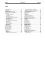
TABLE OF CONTENTS
PREFACE ...............................................................................................................................................3
LIMITED WARRANTY AND LIMITATION OF LIABILITY ........................................................................4
ABOUT PROGRAMMING EXAMPLES ...................................................................................................4
CHAPTER 1: INTRODUCTION...............................................................................................................9
1.1
General..................................................................................................................................... 9
1.2
Overview................................................................................................................................... 9
1.3
Features ................................................................................................................................... 9
1.4
Specifications...........................................................................................................................10
1.5
Signal Descriptions ..................................................................................................................11
1.5.1
Isolated Inputs...................................................................................................................11
1.5.2
Differential Inputs ..............................................................................................................11
1.5.3
Differential Outputs ...........................................................................................................12
1.6
Indicators .................................................................................................................................12
1.7
Motion Profiles .........................................................................................................................12
CHAPTER 2: INSTALLATION..............................................................................................................15
2.1
General....................................................................................................................................15
2.2
Installation ...............................................................................................................................15
2.3
External Wiring.........................................................................................................................16
2.4
Addressing...............................................................................................................................17
CHAPTER 3: CONFIGURATION..........................................................................................................19
3.1
General....................................................................................................................................19
3.2
Configuration ...........................................................................................................................19
3.2.1
Select the Module to be Configured...................................................................................19
3.2.2
Check the Module's I/O Register Assignments ..................................................................21
3.2.3
Configure the Module ........................................................................................................21
CHAPTER 4: REGISTERS ...................................................................................................................23
4.1
General....................................................................................................................................23
4.2
STP100 Module OCS Register Details .....................................................................................24
4.2.1
Error and Status Input Bit Register Details (%I1 - %I16) ....................................................24
4.2.2
Status Word Input Register Details (%AI1 - %AI4).............................................................25
4.2.3
Command Word Output Register Details (%AQ1 - %AQ7 or %AQ1 - %AQ14) ..................26
4.2.4
Command Bit Output Register Details (%Q1 - %Q16)........................................................29
CHAPTER 5: COMMANDS ..................................................................................................................31
5.1
General....................................................................................................................................31
5.2
Issuing Commands ..................................................................................................................31
5.3
Available Commands ...............................................................................................................31
5.3.1
Clear Error(s) Command ...................................................................................................31
5.3.2
Find Origin Up and Find Origin Down Commands..............................................................32
5.3.3
Jog Up and Jog Down Commands ....................................................................................33
5.3.4
Move Relative and Move Absolute Commands..................................................................34
5.3.5
Move Indexed Command ..................................................................................................35
5.3.6
Repeat Move Command....................................................................................................36
5.3.7
Resume Move Command..................................................................................................36
5.3.8
Set Current Position Command .........................................................................................37
5.3.9
Decelerate and Stop Command.........................................................................................37
5.3.10 Immediate Stop Command................................................................................................38
PAGE 8
SUP0270-02
10 FEB 2000
PREFACE
CHAPTER 6: USING ENCODERS........................................................................................................39
6.1
General....................................................................................................................................39
6.2
Adding an Encoder...................................................................................................................39
6.2.1
Quadrature Encoder..........................................................................................................39
6.2.2
Up / Down Encoder ...........................................................................................................40
6.3
Configuring the Encoder...........................................................................................................40
6.3.1
Configuring Step Pulse to Encoder Feedback Ratio...........................................................40
6.3.2
Configuring Encoder Tolerance .........................................................................................41
6.3.3
Configuring Motor Stall Detection ......................................................................................42
CHAPTER 7: WIRING ..........................................................................................................................43
7.1
General....................................................................................................................................43
7.2
Translator Drives......................................................................................................................43
7.3
Encoders..................................................................................................................................44
7.4
Isolated Switch Inputs ..............................................................................................................45
INDEX ...................................................................................................................................................47
CH. 1: INTRODUCTION
10 FEB 2000
PAGE 9
SUP0270-02
CHAPTER 1: INTRODUCTION
1.1
General
Chapter One provides a brief overview of the SmartStack Stepper Positioning Module (HE800STP100).
1.2
Overview
The SmartStack Stepper Positioning Module (STP100) is an intelligent, programmable motion control
SmartStack module, for use with Horner APG Operator Control Station (OCS) products. The STP100 is
capable of interfacing to a wide variety of stepper motors, limit switches, and encoder feedback devices.
1.3
Features
-Single axis motion controlled by application ladder program
-Up to 245,730 steps or micro-steps per second
-Programmable position, velocity, acceleration and deceleration
-Automatic ramp-down deceleration calculation
-Moves can be specified as absolute, relative or indexed
-Relative and indexed moves can be auto-repeated
-Automatic find origin functions
-Manual jogging functions
-Home and over-travel inputs
-Emergency stop input
-Incremental encoder feedback inputs
-Power / watchdog timeout safety interlock
PAGE 10
SUP0270-02
1.4
10 FEB 2000
CH. 1: INTRODUCTION
Specifications
Table 1.1 – Stepper Input and Outputs
ISOLATED INPUTS
LOW LEVEL (+2mA)
ISOLATION
Emergency Stop (ES)
Emergency Stop (ES)
Home (HO)
Home (HO)
0 - 9 VDC
500 VDC min.
Index (IN)
Index (IN)
High Limit (HI)
High Limit (HI)
Low Limit (LO)
Low Limit (LO)
DIFFERENTIAL INPUTS
Encoder Frequency
Encoder Differential
0 - 1.0 MHz
-0.2 VDC min.
Threshold Low
Encoder Single-Ended
1.2 – 1.6 VDC
Encoder Differential
+0.2 VDC max.
Threshold
Threshold High
DIFFERENTIAL OUTPUTS
Step Frequency
0 - 245 KHz
Direction Output Setup Time
2 ms. max.
Step Output High @ -20 mA
2.5 VDC min.
Direction Output High @ -20 mA
2.5 VDC min.
Step Output Low @ +20 mA
0.5 VDC max.
Direction Output Low @ +20 mA
0.5 VDC max.
GENERAL SPECIFICATIONS
26.0mA @ 5VDC
See MAN0005
* Required Power (Steady State)
** CE Rating
64.8mA @ 5VDC in
UL
Pending
* Required Power (Inrush)
10µS
Relative Humidity
5 to 95% NonTerminal Type
Spring Clamp,
condensing
Removable
Operating Temperature
Weight
9.5 oz. (270 g)
0° to 60° Celsius
Storage Temperature
-40° to +85° Celsius
*
**
As measured at the PLC (OCS 100 / 200 or RCS210).
Shielded cables must be used for the discrete inputs to this module (pins 1-7) to obtain immunity protection
specifed by the EN50082-2:92. Failure to do so subjects the equipment to Criterion B failure and voids the CE
rating of this product.
CH. 1: INTRODUCTION
10 FEB 2000
1.5
Signal Descriptions
1.5.1
Isolated Inputs
PAGE 11
SUP0270-02
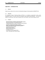
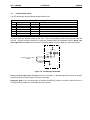
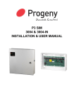
Emergency Stop, Home, Low Limit, High Limit, and Index are optically isolated using the following
circuitry. [Circuitry inside the dotted line is physically located inside the SmartStack module.] Home, Low
Limit, High Limit, and Index can accept either mechanical switch closures or NPN-type proximity switches.
+24VDC
3.9K
24K
Normally Open (N/O)
switch
Isolated
Ground
Figure 1.1 – Isolated Input Schematic
Home, Low Limit, High Limit, and Index are active low signals. A Normally Open (N/O) switch is required
to switch these lines to ground when the switch is activated.
Emergency Stop is an active high signal. A Normally Closed (N/C) switch is required to hold this line to a
LOW (grounded) condition for normal operation of the system.
1.5.2
Differential Inputs
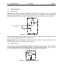
The Encoder Inputs Encoder A, Encoder B and Marker accept differential inputs (Circuitry inside the dotted
line is physically located inside the SmartStack module.) They have RS-485 thresholds. The + inputs are
also TTL compatible when connected to single-ended encoder outputs of suitable polarity.
+
-
Figure 1.2 – Differential Input Schematic
PAGE 12
SUP0270-02
1.5.3
10 FEB 2000
CH. 1: INTRODUCTION
Differential Outputs
Step and Direction Output Signals have RS-485 drive capability and can be interfaced with TTL level inputs
of suitable polarity.
+
-
Figure 1.3 – Differential Output Schematic
1.6
Indicators
The STP100 provides three (3) LED indicators:
Indicator Color
Red
Yellow
Green
1.7
Table 1.2 – LED Indicators
Function
Motor is Stopped
Motor is Accelerating or Decelerating
Motor has reached Running Velocity
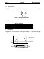
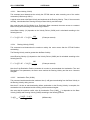
Motion Profiles
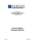
For a typical move, the STP100 starts at a low Base Velocity, accelerates up to the Running Velocity, and
later decelerates down to the Base Velocity, and then stops. This is known as the trapezoidal motion profile,
and is shown in Figure 1.4 below.
Start Position
End Position
Running Velocity
Steps
per
Second
Base Velocity
Accel
Run
Decel
Time
Figure 1.4 – Trapezoidal Motion Profile
CH. 1: INTRODUCTION
10 FEB 2000
PAGE 13
SUP0270-02
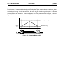
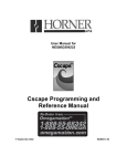
For a given set of programmed Acceleration and Deceleration Times, a particular move can be too short to
allow the motor to accelerate all the way up to Running Velocity. If it is time to start decelerating before
accelerating to Running Velocity has completed, the motor will start decelerating at that point. In this case,
2
the acceleration and deceleration rates (in pulses-per-second ) are preserved, but the acceleration and
deceleration times are decreased. When this happens, the velocity profile becomes triangular, as shown in
Figure 1.5 below.
Start Position
End Position
Running Velocity
Steps
per
Second
Base Velocity
Accel
Decel
Time
Figure 1.5 – Triangular Motion Profile
PAGE 14
SUP0270-02
10 FEB 2000
NOTES
CH. 1: INTRODUCTION
CH. 2: INSTALLATION
10 FEB 2000
PAGE 15
SUP0270-02
CHAPTER 2: INSTALLATION
2.1
General
Chapter Two describes the installation of the STP100 module on the Operator Control Station (OCS) chassis.
2.2
Installation
WARNING: The STP100 must not be installed while power is applied to the OCS- or when the cables to the
motor drive are attached to the SmartStack I/O connector. Always ensure that the motor is disconnected and
that power to the OCS is OFF. The power to the OCS must be unplugged.
The STP100 can be placed in any SmartStack slot.
Caution: To function properly and to avoid possible damage, do not install more than four
Smart Stack Modules per OCS or RCS.
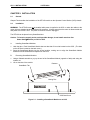
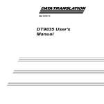
A.
Installing SmartStack Modules
1. Hook the tabs. Each SmartStack Module has two tabs that fit into slots located on the OCS. (The slots
on the OCS are located on the back cover.)
2. Press the SmartStack Module into the locked position, making sure to align the SmartStack Module
fasteners with the SmartStack receptacles on the OCS.
B.
Removing SmartStack Modules
1. Using a flathead screwdriver, pry up the end of the SmartStack Module (opposite of tabs) and swing the
module out.
2. Lift out the tabs of the module.
Fastener
SmartStack Tab
Mating Pins
OCS Back Cover
Figure 2.1 – Installing a SmartStack Module on an OCS
PAGE 16
SUP0270-02
2.3
10 FEB 2000
CH. 2: INSTALLATION
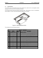
External Wiring
The STP100 requires user-supplied external wiring between the module and the user-supplied external
equipment, such as motor drive, limit switches and encoder.
The STP100 provides nineteen (19) external connection points. Not all points are used in all installations.
When installed on an OCS, the STP100 SmartStack appears as the following:
Pin 1
Pin 19
Figure 2.2 – STP100 Attached to an OCS
The nineteen pins have the following functions:
Pin
1
2
3
4
5
6
7
8
9
10
11
12
13
14
15
16
17
18
19
Signal
Isolated Common
ESTOP+
LOLIMHILIMHOMEINDEXIsolated Common
Common
MARK+
MARKENCA+
ENCAENCB+
ENCBDIR+
DIRSTEP+
STEPCommon
Table 2.1 – I/O Pin-Out
Marking
Description
IC
Isolated Common
ES
Emergency Stop, Active High (Open), 24VDC pullup
LO
Low Limit, Active Low (Closed) 24 VDC pullup
HI
High Limit, Active Low (Closed) 24 VDC pullup
HO
Home, Active Low (Closed) 24 VDC pullup
IN
Index, Active Low (Closed) 24 VDC pullup
IC
Isolated Common
C
Connected to internal Bus Common
M+
Encoder Marker Positive Input
MEncoder Marker Negative Input
A+
Encoder Channel A Positive Input
AEncoder Channel A Negative Input
B+
Encoder Channel B Positive Input
BEncoder Channel B Negative Input
D+
Direction Positive Output
DDirection Negative Output
S+
Step Positive Output
SStep Negative Output
C
Connected to internal Bus Common
CH. 2: INSTALLATION
2.4
10 FEB 2000
PAGE 17
SUP0270-02
Addressing
The STP100 module requires sixteen (16) digital input registers (%I), sixteen (16) digital output registers
(%Q), four (4) analog input register (%AI), and seven (7) or fourteen (14) analog output registers (%AQ)
depending on how the module is configured. The location of these registers within OCS I/O register space is
determined by the type, number, and location of any installed SmartStack modules.
The OCS automatically assigns the I/O register space based on the physical position of the SmartStack
Module. The first module, the one installed next to the main body of the OCS, is Module 1. Module 1 is
always assigned to %I01, %Q01, %AI01 and %AQ01 in any combination required by the SmartStack module.
The addressing of subsequent modules is determined by the addressing of those modules before it. This
assignment is automatic and makes the most efficient use of I/O register space.
For example, assume that Module 1 is a HE800DIM210. This module requires eight (8) %I registers, no %Q
registers, no %AI registers, and no %AQ registers. Its %I registers are %I01 through %I08, inclusive.
Now assume that the STP100 is Module 2. The STP100 require sixteen (16) %I registers. Because of the
previously installed DIM210, the STP100's %I registers are %I09 through %I24, inclusive.
Since no other installed modules have yet required %Q or %AI, the OCS assigns the STP100's registers to
%Q01 through %Q16 and %AI01 through %AI04.
The STP100 requires either seven (7) or fourteen (14) %AQ registers, depending on how the module is
configured. Since no other installed modules have yet required a %AQ register, the OCS assigns the
STP100 to %AQ01 through %AQ07, or %AQ01 through %AQ14, depending on the configuration.
This can be summarized by checking the module I/O Map dialog box, as described in Chapter 3. The dialog
box indicates the addressing and size of the required I/O register space. This setup is assigned by the OCS
and can not be changed.
PAGE 18
SUP0270-02
10 FEB 2000
NOTES
CH. 2: INSTALLATION
CH. 3: CONFIGURATION
10 FEB 2000
PAGE 19
SUP0270-02
CHAPTER 3: CONFIGURATION
3.1
General
Chapter Three describes the steps necessary to configure the STP100 module and the OCS it is attached to.
The procedures for using Cscape software are also described.
3.2
Configuration
Configuration is usually completed after the modules are installed. With Cscape, however, OCS configuration
is contained with the source code (.CSP) files. The OCS can be configured before the modules are installed
or even if the OCS is not available. This is a great convenience when programming must start before the
hardware has been received.
3.2.1
Select the Module to be Configured
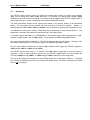
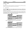
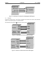
First, invoke Cscape. From the Cscape Main Menu, select Controller | I/O Configure… .
Next, double-click on the empty slot in which the STP100 module will reside, or click on the Config button to
the right of the slot position.
Double click here…
or click here
Figure 3.1 – Select the Module Slot
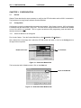
This invokes the Add I/O Module screen. Click on the Other tab:
Select the OTHER tab.
Figure 3.2 – Select the Other Modules tab
PAGE 20
SUP0270-02
10 FEB 2000
CH. 3: CONFIGURATION
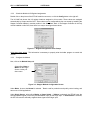
Then select the STP100 module:
Select the STP100 module
Figure 3.3 – Select the STP100 Module
Figure 3.4 – STP100 Module is Added
The screen returns to the Configure I/O dialog box- with the selected slot showing that the Stepper Controller
module has been added.
It is vital that the module and slot match that of the OCS. Mismatched configurations cause an I/O Module
Mismatch Error during the power-on diagnostics of the OCS.
CH. 3: CONFIGURATION
3.2.2
10 FEB 2000
PAGE 21
SUP0270-02
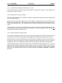
Check the Module's I/O Register Assignments
Double click on the picture of the STP100 module’s connector, or click the Config button to the right of it.
The I/O MAP tab shows the I/O register locations assigned to this module. These values are assigned
automatically by Cscape and the OCS. These values are not configurable by the user except by installing the
Stepper Controller Module in another position in the SmartStack stack. If the Stepper Controller is the only
module installed on this OCS, then there is no way to reconfigure these values.
Figure 3.5 – Register Assignments from Cscape
Write down these values. This information is necessary to properly write the ladder program to control this
module.
3.2.3
Configure the Module
Now, click on the Module Setup tab.
Select either Home or
Marker as the Origin
Source via the pulldown menu.
Figure 3.6 – Stepper Module Configuration Screen
Under Mode, be sure that Normal is selected. Test is used for production and quality control testing, and
has no use in field applications.
Under Origin Source, select either Marker or Home Switch. If Marker is selected, the STP100 uses the
encoder's Marker signal (or the user-provided Marker input) as the Origin input. If Home Switch is selected,
the STP100 uses the externally supplied Home signal as the Origin input.
PAGE 22
SUP0270-02
10 FEB 2000
CH. 3: CONFIGURATION
In the Find Origin box, select either the Normal Method or the Simple Method. With the Simple Method,
when a Find Origin command is issued, the STP100 moves the motor until the Origin position is located and
then stops. With the Normal Method, the STP100 moves the motor quickly until the Origin position is
located, then backs up and re-approaches the Origin position at a slower rate. The Simple Method assumes
the motor is initially moving slowly enough, such that it does not overshoot the Origin position.
Checking the Limit Switch Qualified box causes the Find Origin command to first search for a limit switch
before searching for the Origin. This is especially useful when an encoder marker is being used as the Origin
Source.
Under Encoder Configuration select Encoder Type – None, Quadrature or Up/Down. Absolute encoders
and resolvers are not compatible with the STP100. With Quadrature selected, Encoder A and Encoder B
accept phases A and B respectively from an encoder that supplies quadrature outputs. With Up/Down
selected, Encoder A and Encoder B accept Up and Down signals respectively from an encoder that supplies
Count Up and Count Down outputs.
When Encoder Type is not None, the other Encoder Configuration items (Multiplier, Divisor, Tolerance
and Stall Detection) all become available for configuration. Enter suitable numbers into the Multiplier,
Divisor, and Tolerance boxes, and if desired, check the Enable Stall Detection box.
Multiplier and Divisor are used to tell the STP100 about the number of encoder pulses per revolution versus
the number of step pulses per revolution.
For many applications, some small amount of positioning error is acceptable. Setting the Tolerance to some
non-zero value causes the STP100 to compare the encoder feedback value with the desired motor position.
If the result of the comparison is less than the Tolerance value, no error is generated. If the result of the
comparison is greater than the Tolerance value, the Current Position Valid status bit is set False. If
Tolerance is set to 0 (zero) the comparison is not made and no error is indicated.
If the Enable Stall Detection box is checked, the STP100 verifies that encoder feedback pulses are being
received after a move is requested. If encoder pulses are not received, the STP100 assumes that the motor
is not turning, and sets the Motor Stalled error bit True. If Enable Stall Detection is unchecked, no error is
generated if the motor fails to move.
If the application will be using Indexed Moves, check the Enable Indexed Move box. The state of this box
must match that of the Index Move box in the Stepper Move element in the Cscape ladder program. Note
that Indexed Moves require the presence of a user-supplied Index Input signal. If no Index Input signal is
supplied, an Indexed Move behaves exactly like a Relative Move.
When the Enable Indexed Move box is checked, the STP100 module requires 14 %AQ registers instead of
just 7. Be sure to check the modules I/O register assignment if this box is changed. If the STP100 is not the
only SmartStack module installed or the last SmartStack module installed, all subsequent modules find their
I/O register addresses shifted if the Enable Indexed Move box is checked.
CH. 4: REGISTERS
10 FEB 2000
PAGE 23
SUP0270-02
CHAPTER 4: REGISTERS
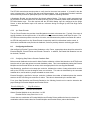
4.1
General
Chapter Four defines the OCS registers used by the STP100 module, and describes how they are used.
For this discussion, it is assumed that the STP100 module is installed as the first SmartStack module in
the OCS. In this case, the STP100 uses OCS registers starting with %I1, %Q1, %AI1 and %AQ1. If the
STP100 is not the first SmartStack module, the actual registers that are used are determined by the type
and position of the other SmartStack modules installed on the OCS. Table 4.1 summarizes STP100
register usage.
Table 4.1 – STP100 Module OCS Register Summary
Error and Status Bit Input Registers
Command Bit Output Registers
Register
Description
Register
Description
%I1
Emergency Stop Error
%Q1
Spare Command (future use)
%I2
Low End Limit Error
%Q2
Spare Command (future use)
%I3
High End Limit Error
%Q3
Spare Command (future use)
%I4
Illegal Move Error
%Q4
Find Origin Up
%I5
Motor Stalled Error
%Q5
Find Origin Down
%I6
Spare Error (future use)
%Q6
Jog Up
%I7
Spare Error (future use)
%Q7
Jog Down
%I8
Power-Up / Watchdog Error
%Q8
Move Relative
%I9
Current Position Valid Status
%Q9
Move Absolute
%I10
Pre-empted Move Resumable Status
%Q10
Resume Move
%I11
Spare Status (future use)
%Q11
Move Indexed
%I12
Spare Status (future use)
%Q12
Repeat Move
%I13
Currently at Origin Position Status
%Q13
Set Current Position
%I14
Motor is Accelerating Status
%Q14
Clear Error(s)
%I15
Motor is Decelerating Status
%Q15
Decelerate and Stop
%I16
Motor is Moving Status
%Q16
Immediate Stop
Status Word Input Registers
Register
Description
Minimum
Maximum
%AI1
Motor Position Lo Word
-8,388,608
+8,388,607
%AI2
Motor Position Hi Word
%AI3
Encoder Position Lo Word
-8,388,608
+8,388,607
%AI4
Encoder Position Hi Word
Command Word Output Registers
Register
Description
Minimum
Maximum
%AQ1
Destination Position Lo Word
-8,388,608
+8,388,607
%AQ2
Destination Position Hi Word
%AQ3
Velocity Divisor
20
65535
%AQ4
Base Velocity (must be < %AQ5)
1
8191
%AQ5
Running Velocity (must be > %AQ4)
1
8191
%AQ6
Acceleration Time (mS)
1
27,300
%AQ7
Deceleration Time (mS)
0
27,300
%AQ8
Indexed Destination Position Lo Word
1
16,777,215
%AQ9
Indexed Destination Position Hi Word
%AQ10
Indexed Deceleration Time (mS)
0
27,300
%AQ11
Indexed Window Open Position Lo Word
1
16,777,215
%AQ12
Indexed Window Open Position Hi Word
%AQ13
Indexed Window Close Position Lo Word
1
16,777,215
%AQ14
Indexed Window Close Position Hi Word
PAGE 24
SUP0270-02
4.2
10 FEB 2000
CH. 4: REGISTERS
STP100 Module OCS Register Details
This section contains detailed information regarding the STP100 module’s use of OCS registers.
4.2.1
Error and Status Input Bit Register Details (%I1 - %I16)
The STP100 uses sixteen (16) Digital Input (%I) registers as Error and Status bits as summarized in
Table 4.1 above. Table 4.2 shows these bits and the status conditions they represent.
Register
%I1
%I2
%I3
%I4
%I5
%I6
%I7
%I8
%I9
%I10
%I11
%I12
%I13
%I14
%I15
%I16
Table 4.2 – Error and Status Input Bit Details
Description
Condition
Emergency Stop Error
Emergency Stop input activated during move
Low End Limit Error
Low Limit input activated during move up
High End Limit Error
High Limit input activated during move down
Illegal Move Error
Previous commanded move was not possible
Motor Stalled Error
Motor is not moving in response to pulses
Spare Error (future use)
Not Used
Spare Error (future use)
Not Used
Power-Up / Watchdog Error
Always ON immediately after power-on or reset
Initially OFF; comes ON after successful Find
Current Position Valid Status
Origin or Set Current Position command; set OFF
again if motor is stopped suddenly or stalls
Pre-empted Move Resumable Status
Pre-empted move can be resumed to completion
Spare Status (future use)
Not Used
Spare Status (future use)
Not Used
Origin Input (Marker or Home depending on
Currently at Origin Position Status
whichever is the configured Origin Source) is
active
Motor is Accelerating Status
Motor is accelerating
Motor is Decelerating Status
Motor is decelerating
Motor is Moving Status
Motor is moving
At power-up or after a watchdog timer reset, all error and status bits are OFF except the PowerUp/Watchdog error bit, which will be ON.
If any error or status bit is ON, it means the corresponding condition is True. Note that if one of the error
bits (%I1 - %I8) is ON, an error has occurred. Error bits stay ON till a Clear Error command (%Q14) is
issued. No other commands can be issued while an error bit is ON. The status bits (%I9 - %I16) reflect
various other STP100 status conditions and are not affected by the Clear Error command.
CH. 4: REGISTERS
4.2.2
10 FEB 2000
PAGE 25
SUP0270-02
Status Word Input Register Details (%AI1 - %AI4)
The STP100 used four (4) Analog Input (%AI) registers to indicate position status. These registers are
summarized in Table 4.1 above.
4.2.2.1 Motor Position (%AI1 and %AI2)
The first 2 status words (%AI1 and %AI2) are treated as a single 32-bit signed integer value representing
the current Motor Position.
Motor Position is continuously updated (up or down) based on step pulses sent by the STP100 to the
stepper motor translator drive. Note that at power up or after a watchdog timer reset, this value is set to
zero and is considered invalid. This is reflected by the fact that the Current Position Valid Status bit (%I9)
is OFF.
The Motor Position continues to be invalid until a Find Origin Up (%Q4), Find Origin Down (%Q5) or Set
Current Position (%Q13) command is executed successfully. Until this happens, the STP100 does not
obey the Move Absolute command (%Q9).
4.2.2.2 Encoder Position (%AI3 and %AI4)
If an encoder is attached to the STP100, and if it is properly configured via Cscape, the %AI3 and %AI4
status words are treated as a single 32-bit signed integer value representing current Encoder Position.
Encoder Position is continuously updated (up or down) based on feedback pulses sent by the encoder to
the STP100. Note that at power up or after a watchdog timer reset, this value is set to zero and is
considered invalid. This is reflected by the fact that the Current Position Valid Status bit (%I9) is OFF.
If the STP100 is properly configured (see section 6.3), Encoder Position tracks Motor Position. Note that
when Encoder Position doesn’t match Motor Position exactly, a position validation error has been
detected. There are several possible causes for this error (see section 6.3.2). Some position validation
errors can’t be avoided, which is why the STP100 supports an Encoder Tolerance configuration
parameter.
PAGE 26
SUP0270-02
4.2.3
10 FEB 2000
CH. 4: REGISTERS
Command Word Output Register Details (%AQ1 - %AQ7 or %AQ1 - %AQ14)
By default, the STP100 uses seven (7) %AQ registers. If the Enable Indexed Moves box is checked on
the STP100’s Module Setup screen, then the STP100 uses at total of fourteen (14) %AQ registers.
The %AQ command words act as qualifiers for the %Q command bits. Typically, the %AQ command
words are set to appropriate values, and then one of the %Q command bits is changed from OFF to ON.
Normally, after the STP100 starts executing a command, the %AQ command words can be changed to
prepare for the next command without affecting the command in progress. The exception to this rule is,
that the Destination Position (%AQ1 and %AQ2) must not be disturbed during a Find Origin Up or Find
Origin Down command, until either an error occurs, or the Current Position Valid status bit goes ON.
4.2.3.1 Destination Position (%AQ1 and %AQ2)
The first two command words (%AQ1 and %AQ2) are treated as a single 32-bit signed integer value
representing the Destination Position. For the Find Origin Up, Find Origin Down and Set Current Position
commands, the Destination Position is the value to be loaded into Motor Position and Encoder Position
when the command completes successfully.
For the Move Absolute command, the Destination Position is the absolute position to move to. For the
Move Relative and Move Indexed commands, the Destination Position is the relative distance to move
above or below the current position.
4.2.3.2
Velocity Divisor (%AQ3)
This command word determines the resolution (multiplier) of the Base Velocity (%AQ4) and the Running
Velocity (%AQ5) command words.
The velocity multiplier (MV), ranges from .01 pulses per second to 30 pulses per second and is calculated
as follows:
MV =
600
% AQ3
(Pulses per second)
Table 4.3 shows some useful %AQ3 settings along with their resulting velocity multipliers and
corresponding maximum velocities.
Velocity Divisor
(%AQ3)
20
60
120
300
600
1200
Table 4.3 - Example Velocity Multipliers
Velocity Multiplier
Maximum Velocity (Pulses Per Second)
(MV)
(MV x 8191)
30.0
245,730.0
10.0
81,910.0
5.0
40,995.0
2.0
16,382.0
1.0
8,191.0
0.5
4,095.5
CH. 4: REGISTERS
4.2.3.3
10 FEB 2000
PAGE 27
SUP0270-02
Base Velocity (%AQ4)
This command word determines the velocity the STP100 starts at when executing one of the motion
commands (%Q4 through %Q11).
A typical move starts at the Base Velocity and accelerate to the Running Velocity. Then, if the move ends
normally, it decelerates from Running Velocity to Base Velocity, and then stops.
Also, near the end of a Find Origin Up or Find Origin Down command, the motor moves at a constant
Base Velocity while searching for the exact Origin Position.
Actual Base Velocity (VB) depends on the Velocity Divisor (%AQ3) and is calculated according to the
following formula:
VB = % AQ 4 × M V = % AQ 4 ×
4.2.3.4
600
% AQ3
(Pulses per second)
Running Velocity (%AQ5)
This command word determines the maximum velocity the motor moves after the STP100 finishes
accelerating.
The Running Velocity must be greater than the Base Velocity.
Actual Running Velocity (VR) depends on the Velocity Divisor (%AQ3) and is calculated according to the
following formula:
VR = % AQ5 × M V = % AQ5 ×
600
% AQ3
(Pulses per second)
Note that if the Destination Position parameter is too short to accommodate the Acceleration Time and
Deceleration Time parameters, the motor never reaches the Running Velocity and the move becomes
triangular.
4.2.3.5
Acceleration Time (%AQ6)
This command word determines the maximum time (in mS) spent accelerating from the Base Velocity to
the Running Velocity during a move.
Note that if it is time to start decelerating before acceleration to the Running Velocity is complete, the
acceleration time is decreased and the velocity profile becomes triangular.
Also note that the maximum useful value for Acceleration Time (%AQ6MAX) is dependent on the Base
Velocity (%AQ4) and Running Velocity (%AQ5) according to the following formula:
% AQ6 MAX ≈
% AQ5 − % AQ 4
0.3
(Milliseconds)
PAGE 28
SUP0270-02
4.2.3.6
10 FEB 2000
CH. 4: REGISTERS
Deceleration Time (%AQ7)
This command word determines the maximum time (in mS) spent decelerating from the Running Velocity
to the Base Velocity at the end of a move. If %AQ7 is zero, deceleration time is the same as the
acceleration time set via %AQ6.
Note that if it is time to start decelerating before acceleration to the Running Velocity is complete, the
deceleration time is decreased, and the velocity profile becomes triangular.
Also note that the maximum useful value for Deceleration Time (%AQ7MAX) is dependent on the Base
Velocity (%AQ4) and Running Velocity (%AQ5) according to the following formula:
% AQ7 MAX ≈
4.2.3.7
% AQ5 − % AQ4
0.3
(Milliseconds)
Indexed Destination Position (%AQ8 and %AQ9)
These two command words (%AQ8 and %AQ9) are treated as a single 32-bit unsigned integer value
representing the Indexed Destination Position.
The Indexed Destination Position contains the number of steps to continue in the current direction after
the STP100 detects external activation of the Index Input during a Move Indexed command (%Q11).
4.2.3.8
Indexed Deceleration Time (%AQ10)
This command word determines the time (in mS) spent decelerating from the Running Velocity to the
Base Velocity at the end of a Move Indexed command (%Q11) after the Indexed Input has been asserted.
If %AQ10 is zero, deceleration time is the same as the normal deceleration time set via %AQ7.
4.2.3.9
Indexed Window Open Position (%AQ11 and %AQ12)
These two command words (%AQ11 and %AQ12) are treated as a single 32-bit unsigned integer value
representing the Window Open Position during a Move Indexed command (%Q11).
The Indexed Window Open Position contains the number of steps past the beginning of an Indexed Move
when the Index Input Window is opened. While the Index Input Window is open, the STP100 module
monitors the external Index Input. While the Index Input Window is closed, the STP100 module ignores
the external Index Input.
4.2.3.10 Indexed Window Close Position (%AQ13 and %AQ14)
These two command words (%AQ13 and %AQ14) are treated as a single 32-bit unsigned integer value
representing the Window Close Position during a Move Indexed command (%Q11).
The Indexed Window Close Position contains the number of steps past the beginning of an Indexed
Movewhen the Index Input Window is closed. While the Index Input Window is open, the STP100 module
monitors the external Index Input. While the Index Input Window is closed, the STP100 module ignores
the external Index Input.
CH. 4: REGISTERS
4.2.4
10 FEB 2000
PAGE 29
SUP0270-02
Command Bit Output Register Details (%Q1 - %Q16)
The STP100 uses sixteen (16) Digital Output (%Q) registers, which are used as Commands. These
registers are summarized in Table 4.1 above.
Most commands are positive (OFF-to-ON) edge sensitive. This means that the STP100 obeys the
command only when the module sees the command bit transition from OFF to ON. The STP100 can
require more than one OCS logic scan to detect a command bitbut takes no more than 2 mS to start
executing the command. The command bit must then be turned OFF for at least 2 mS before the next
command (or the same command) can be again issued.
The Jog Up and Jog Down commands are level sensitive. The Jog commands start when the OFF-to-ON
transition is recognized and remain running so long as the command bit stays ON. The Jog commands
decelerate and stop when the ON-to-OFF transition is recognized.
The Power Up / Watchdog Error Status bit (%I8) is always ON immediately after Power-On or reset.
Therefore, the first command issued must be the Clear Errors command (%Q14).
Also, some commands are ignored depending on the state of other status bits. For example, if the
Moving Status bit (%I16) is ON, the only legal commands are Decelerate and Stop (%Q15) and
Immediate Stop (%Q16).
If more than one command bit goes active during any one CPU Scan Time, the command with the
highest bit number takes priority. Note that this gives the Immediate Stop command (%Q16) the highest
priority.
PAGE 30
SUP0270-02
10 FEB 2000
NOTES
CH. 4: REGISTERS
CH. 5: COMMANDS
10 FEB 2000
PAGE 31
SUP0270-02
CHAPTER 5: COMMANDS
5.1
General
Chapter Five describes the commands available for the STP100 and their operations.
5.2
Issuing Commands
Commands are issued by setting the appropriate bit in the Command Bit Output registers.
Commands can be issued only under strict conditions as described in the individual command
descriptions that follow.
The STP100 does not accept commands if any of the Error Status bits are ON. The exception is, of
course, the Clear Errors command (%Q14). If an error occurs, the only command that can be issued is
the Clear Errors command. Note that immediately following a power-up or reset, the Power-Up /
Watchdog Error bit is ON. Thus, the first command issued after a power on or reset must be the Clear
Errors command. This is a safety feature, which prevents the STP100 from running until the application
program is in control, and specifically issues the Clear Errors command.
5.3
Available Commands
5.3.1
Clear Error(s) Command
Command Bit:
%Q14
Status Bits Required:
Status Bits Affected:
Status Words Required:
Status Words Affected:
Command Words Required:
None
%I1 through %I8
None
None
None
This command is used to clear errors previously detected by the STP100. When this command is issued,
all Error bits (%I1 through %8) are cleared (turned OFF).
Note that when an Error bit is ON, the STP100 does not obey any other commands till the error is cleared
via the Clear Error(s) command.
The Power Up / Watchdog Error bit (%I8) provides a safety interlock. This bit is ON immediately after
power-ON, reset or watchdog timeout. The Stepper Controller does not accept any other commands until
this bit is cleared using the Clear Errors command. Therefore, the Clear Errors command must be the
first command issued after a power-ON or reset.
PAGE 32
SUP0270-02
5.3.2
10 FEB 2000
CH. 5: COMMANDS
Find Origin Up and Find Origin Down Commands
Command Bits:
%Q4 and %Q5
Status Bits Required:
Status Bits Affected:
Status Words Required:
Status Words Affected:
Command Words Required:
%I1 through %I8 and %I16 must be OFF
%I1 through %I5, %I9 and %I13 through %I16
None
%AI1 through %AI4
%AQ1 through %AQ6
These commands are used to search for the Origin Reference Position as follows:
%Q4
%Q5
Searches for Origin Position in the Up direction
Searches for Origin Position in the Down direction
In the following discussion, Origin Source is either the Home Input or the Marker Input, depending on
how the STP100 module is configured (see section 3.2.3). When searching for Origin Position, the
following search sequence takes place:
1. The Current Position Valid status bit (%I9) is turned OFF (position not valid).
2. The motor is moved normally (starts at Base Velocity and accelerates to Running Velocity) in the
selected direction (up for %Q4 or down for %Q5).
3. When the Origin Source becomes active, motion is stopped immediately.
4. If the Simple Method radio button was selected during configuration, skip to step 8. NOTE: The
Simple Method variation assumes that the user-programmed Running Velocity is slow enough to
prevent overshoot.
5. Otherwise, just in case we shot right past the Origin, the motor is run at Base Velocity in the opposite
direction till the Origin Source is active again.
6. Motion then continues in the same direction as in step 5 above, (still at Base Velocity), till the Origin
Source is inactive for 50 mS.
7. Then the direction is reversed again, and the motor is moved at Base Velocity till the Origin Source
is active, at which time the motor stops precisely at the Origin Position.
8. Destination Position is copied into Motor Position and into Encoder Position, and the Current Position
Valid Status bit (%I9) is turned ON.
If the Limit Switch Qualified box was checked during configuration, step 3 above is changed
as follows:
3. When the End Limit input for the direction we’re moving becomes active, motion is stopped
immediately.
NOTE: The Limit Switch Qualified variation is most useful when the Origin Source is configured to be
the Marker Input. Since the Marker on a rotary encoder typically occurs several times during a full stroke
move, this technique allows the Marker, which occurs closest to the Limit Switch, to be used as the Origin
Position.
For best results, the Marker-to-Limit-Switch relationship needs to be mechanically adjusted such that the
Marker occurs at approximately one-half of the encoder’s revolution away from the Limit Switch.
CH. 5: COMMANDS
5.3.3
10 FEB 2000
PAGE 33
SUP0270-02
Jog Up and Jog Down Commands
Command Bits:
%Q6 and %Q7
Status Bits Required:
Status Bits Affected:
Status Words Required:
Status Words Affected:
Command Words Required:
%I1 through %I8 and %I16 must be OFF
%I1 through %I5 and %I13 through %I16
None
%AI1 through %AI4
%AQ3 through %AQ7
These commands are used to perform manual jogging as follows:
%Q6
%Q7
Starts a manual jog move in the Up direction
Starts a manual jog move in the Down direction
When one of the Jog Command bits goes ON, the motor starts in the selected direction at the Base
Velocity and accelerates to the Running Velocity.
The motor continues to move at Running Velocity until the Jog Command bit goes OFF again. At that
time, the motor decelerates from Running Velocity back down to Base Velocity, and then stop.
If the Jog Command bit transitions from ON to OFF before the motor reaches Running Velocity, the motor
acceleration and deceleration times is decreased, and the velocity profile is triangular.
PAGE 34
SUP0270-02
5.3.4
10 FEB 2000
CH. 5: COMMANDS
Move Relative and Move Absolute Commands
Command Bits:
%Q8 and %Q9
Status Bits Required:
%I1 through %I8 and %I16 must be OFF;
%I9 must be ON for %Q9 command
%I1 through %I5 and %I13 through %I16
%AI1 and %AI2 used by %Q9 command
%AI1 through %AI4
%AQ1 through %AQ7
Status Bits Affected:
Status Words Required:
Status Words Affected:
Command Words Required:
These commands perform a relative or absolute move as follows:
%Q8
%Q9
Performs a relative move
Performs an absolute move
Both of these commands perform a programmed move in the up or down direction to a relative target
position.
If doing a relative move (%Q8), the relative target position is taken directly from Destination Position
(%AQ1 and %AQ2) and it is not necessary for the Current Position Valid Status bit (%I9) to be On. The
direction of the move is determined by the Destination Position sign (+ for move up or - for move down).
If doing an absolute move (%Q9), the relative target position is calculated as the difference between
Destination Position (%AQ1 and %AQ2) and Motor Position (%AI1 and %AI2), and therefore it is
necessary for the Current Position Valid Status bit (%I9) to be On. The direction of the move depends on
whether Destination Position is higher (move up) or lower (move down) than Motor Position.
Normally, the move starts at Base Velocity and accelerates to Running Velocity until it is time to
decelerate back down to Base Velocity, and then stop. This type of move is said to have a trapezoidal
velocity profile.
If it is time to start decelerating (before accelerating to Running Velocity has completed), the motor
starts decelerating at that point. In this case, the acceleration and deceleration times are decreased, and
the velocity profile becomes triangular.
Optionally, the End Limit Inputs can be used to start relative and absolute moves. The High Limit Input
(HILIM-) can be used to start moves in the Up direction while the Low Limit Input (LOLIM-) can be used to
start moves in the Down direction. To accomplish this, the ladder program needs to be set up the %AQ
values as for a normal relative or absolute move, and the appropriate End Limit Input needs to be
activated before %Q8 or %Q9 is turned ON. In this case, the actual move does not start until the End
Limit input is deactivated.
CH. 5: COMMANDS
5.3.5
10 FEB 2000
PAGE 35
SUP0270-02
Move Indexed Command
Command Bit:
%Q11
Status Bits Required:
Status Bits Affected:
Status Words Required:
Status Words Affected:
Command Words Required:
%I1 through %I8 and %I16 must be OFF
%I1 through %I5 and %I13 through %I16
None
%AI1 through %AI4
%AQ1 through %AQ14
This command performs an Indexed Move, which is similar to a Relative Move (%Q8), except that the
final destination can be modified if the external Index Input becomes active. This modified behavior is
determined by the user-programmed values in %AQ8 through %AQ14. Note that %AQ8 through %AQ14
are ignored by all other STP100 commands.
For details on %AQ8 through %AQ14 values, refer to Table 4.1 and to Section 4.2.3 in Chapter 4.
As stated above, the Indexed Move is similar to the Relative Move. In fact, if the Index Input does not
become active during an Indexed Move, it behaves exactly like a Relative Move.
The purpose, of the Move Indexed command, is to provide the ability to synchronize motor movement
with an external mechanical reference point. This reference point (or index) is provided to the STP100
module via the Index Input. The Index Input will only be processed if it occurs during a user-specified
window. When the Index Input is accepted, the STP100 then switches to an alternate destination and an
alternate deceleration time.
When the %Q11 bit goes ON, the motor starts moving just as it would for a Relative Move. However,
during the time the Indexed Window is open (determined by %AQ11 through %AQ14), the STP100
monitors the Index Input. If the Index Input becomes active while the Indexed Window is open, a new
end point for the move is determined. This new end point is defined to be N more steps (in the same
direction) beyond the point at which the Index Input became active, where N is the Indexed Destination
Position (%AQ8 and %AQ9) value. In addition, if %AQ10 is not zero, it sets a new deceleration point
called the Indexed Deceleration Time.
The resulting Indexed Move can be longer or shorter than the default Relative Move. The motor must
attain Running Velocity before the window is opened. If the move does not reach Running Velocity the
window won’t be opened, and the Index Input is not accepted.
If the Relative Move reaches the point to begin decelerating before the Index Input is activated, the
window is closed and Index Input is not accepted.
The STP100 must be specifically configured to accept Indexed Moves (see section 3.2.3). Configuring an
STP100 for Indexed Moves increases the number of required Command Word Output Registers (%AQ)
registers from seven (7) to fourteen (14).
NOTE: A Move Indexed command has one more difference compared to other move commands. In
applications where all moves are in the same direction, the DIR+ and DIR- outputs can be used
as MOVING+ and MOVING- outputs, indicating Move in Progress to some external device.
At the start of a Relative, Absolute or Indexed move, DIR+ and DIR- are set according to the
direction of the move. At the end of a Relative and Absolute move, the DIR+ and DIR- outputs do
not change state. However, at the end of an Indexed Move, DIR+ and DIR- are always taken
Low and High respectively. Therefore, when an Indexed Move starts in the Up direction, DIR+
and DIR- start out High and Low respectively, and then switch to Low and High respectively when
the move completes.
PAGE 36
SUP0270-02
5.3.6
10 FEB 2000
CH. 5: COMMANDS
Repeat Move Command
Command Bit:
%Q12
The Repeat Move command is not really a command at all but can be used to automatically repeat a
Relative Move (%Q8) or an Indexed Move (%Q11) command.
When a Relative Move or Indexed Move completes normally, the STP100 checks the %Q12 bit. If the
%Q12 bit is ON, the STP100 automatically repeats the move just completed. As long as the %Q12 bit
stays ON, the move is repeated immediately after completion of each move.
If the %Q12 bit is turned OFF during a move, the current move will still complete normally, but it will not
be repeated.
5.3.7
Resume Move Command
Command Bit:
%Q10
Status Bits Required:
%I1 through %I8 and %I16 must be OFF
%I10 must be ON
%I1 through %I5, %I10 and %I13 through %I16
None
%AI1 through %AI4
None
Status Bits Affected:
Status Words Required:
Status Words Affected:
Command Words Required:
This command can be used to resume a previously pre-empted Relative Move or Absolute Move.
If a Move Relative or Move Absolute command was previously pre-empted by a Decelerate and Stop
command (%Q15), and no other commands have been issued since then, the Pre-empted Move
Resumable Status bit is ON.
In this case, the Resume Move command can be issued to restart the pre-empted move from where it left
off. Of course, this action turns the Pre-empted Move Resumable Status bit back OFF.
Note that the resume logic is such that a move can be pre-empted and resumed any number of times
until one of the following occurs:
1. The move reaches its originally programmed relative target position,
2. An error occurs (such as End Limit or Emergency Stop),
3. Some command other than %Q10 is issued after a move is pre-empted.
The Resume Move command is especially useful for manually-assisted programmed moves.
For example, the machine operator can trigger a Move Absolute command by pressing a footswitch. If
the footswitch continues to be pressed, the move continues until it reaches its programmed target
position.
However, at the operator's option, the footswitch can be released causing a Decelerate and Stop
command to be issued. There are a number of reasons why the operator might decide to do this, such as
to make a mechanical adjustment or to manually reposition the material being moved.
Then, when the operator is ready, the footswitch can be pressed again sending a Resume Move
command to the STP100 to complete the motion.
CH. 5: COMMANDS
5.3.8
10 FEB 2000
PAGE 37
SUP0270-02
Set Current Position Command
Command Bit:
%Q13
Status Bits Required:
Status Bits Affected:
Status Words Required:
Status Words Affected:
Command Words Required:
%I1 through %I8 and %I16 must be OFF
%I9
None
%AI1 through %AI4
%AQ1 and %AQ2
This command is used to manually set the current position.
When the Set Current Position command is issued, Destination Position (%AQ1 and %AQ2) is copied
into Motor Position (%AI1 and %AI2) and Encoder Position (%AI3 and %AI4), and the Current Position
Valid Status bit (%I9) is turned On.
This command can be used in conjunction with the Jog Up and Jog Down commands as an alternative to
the Find Origin Up and Find Origin Down commands for finding and setting a reference position.
There is no motor movement associated with this command.
5.3.9
Decelerate and Stop Command
Command Bit:
%Q15
Status Bits Required:
Status Bits Affected:
Status Words Required:
Status Words Affected:
Command Words Required:
None
%I10, %I13 through %I16
None
%AI1 through %AI4
None
This command causes the controller to decelerate and stop the motor.
If the motor is moving when this command is issued, the motor decelerates till it reaches the Base
Velocity, and then it stops.
If this command pre-empts a Move Relative or Move Absolute command, the Pre-empted Move
Resumable Status bit (%I10) is turned ON, unless an error occurs. In this case, the original move can be
resumed from where it left off by issuing a Resume Move command (%Q10).
PAGE 38
SUP0270-02
10 FEB 2000
CH. 5: COMMANDS
5.3.10 Immediate Stop Command
Command Bit:
%Q16
Status Bits Required:
Status Bits Affected:
Status Word Required:
Status Word Affected:
Command Words Required:
None
%I9, %I13 through %I16
None
%AI1 through %AI4
None
This command is used to cause the motor to stop immediately. When this command is issued, the motor
stops as quickly as possible.
If the motor was moving, the Current Position Valid Status bit (%I9) is turned OFF.
CH. 6: USING ENCODERS
10 FEB 2000
PAGE 39
SUPO270-02
CHAPTER 6: USING ENCODERS
6.1
General
Chapter Six details the use of optional encoder feedback with the STP100.
6.2
Adding an Encoder
The encoder must be of a type accepted for use with the motor selected. Read the information supplied with
the motor for further instructions on selecting and installing an encoder on the motor.
The STP100 can be configured for one of three encoder types – None, Quadrature or Up/Down.
encoders and resolvers are not compatible with the STP100. If the Encoder Type is None, the
Position Status Word registers (%AI3 and %AI4) need to be ignored, and the Motor Stalled Error
never goes ON. Otherwise, if the Encoder Type is configured for Quadrature or Up/Down, the
Position Status Word registers are updated as a result of feedback pulses from the Encoder to the
thus allowing Motor Position validation and Motor Stall detection.
Absolute
Encoder
bit (%I5)
Encoder
STP100,
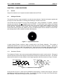
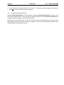
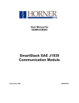
Figure 7.1 - Typical Encoder Disk
A typical Optical Encoder contains a glass or plastic disk in the Encoder Assembly. The encoder is
mechanically attached to the motor such that the encoder disk and motor shaft turn together. Typically, an
optical sensor fits over the edge of the encoder disk. As the disk turns, the sensor generates the A and B
pulses, which are amplified to TTL or RS-485 levels, and then are sent to the STP100 through short cables.
6.2.1
Quadrature Encoder
The Quadrature Encoder is the most common position feedback device used in motion control. This type of
encoder outputs two square wave signals (A and B) which are 90° out of phase with each other. The STP100
determines the direction of motion based on which signal lags behind the other as shown in Figure 7.2 below.
Phase
Phase
123012
A
A
B
B
A leads B
1 2301 2
A lags B
Figure 7.2 – Quadrature Encoder Signals
As can be seen in Figure 7.2, there are two possibilities of signal timing: A leads B, and A lags B. These two
possibilities are set by the direction of the motor. For example, if the motor is moving in the forward direction,
then A leads B. If the motor is moving in reverse, then A lags B.
PAGE 40
SUP0270-02
10 FEB 2000
CH. 6: USING ENCODERS
The STP100 counts these encoder pulses to verify how far the motor has traveled. If A leads B, then the
count is incremented. If A lags B, then the count is decremented. Also, a Quadrature Encoder’s resolution
can be effectively doubled or quadrupled by the STP100’s quadrature decoding hardware.
A Quadrature Encoder can also provide a third signal, called a Marker. This signal, usually generated once
per revolution of the motor's shaft, can be used by the STP100 as a reference position when connected to the
STP100’s Marker Input. This also requires that the STP100’s Marker Input be configured as the Origin
Source, to allow the Marker Input to be used as a reference during Find Origin Up and Find Origin Down
commands.
6.2.2
Up / Down Encoder
The Up / Down Encoder also provides A and B signals but not both at the same time. Typically, if the motor is
turning clockwise, the A output is active. If the motor is turning counterclockwise, the B output is active. The
STP100 increments the position count when A is active, and decrements the position count when B is active.
An STP100 configured for an Up / Down Encoder is especially useful for unidirectional motion control, in
which some mechanical event provides the feedback, such as a proximity detector monitoring gear teeth.
6.3
Configuring the Encoder
After configuring Encoder Type as either Quadrature or Up / Down, appropriate values should be entered for
Encoder Multiplier, Encoder Divisor and Encoder Tolerance. In addition, the Enable Stall Detection box can
be checked, if desired.
6.3.1
Configuring Step Pulse to Encoder Feedback Ratio
Before encoder feedback can be used for Motor Position validation or Motor Stall detection, the STP100 must
know the ratio of motor step pulses to encoder feedback pulses. This is accomplished by setting the Encoder
Multiplier and the Encoder Divisor to values, which are appropriate for the user-supplied hardware.
Step Resolution, specified in micro-steps per revolution, indicates the number of step pulses which must be
sent by the STP100, to move the stepper motor one revolution. This value is determined by the connected
translator drive, and is switch or jumper selectable on some drives.
Encoder Resolution, specified in lines per revolution, indicates the number of feedback pulses the encoder
sends to the STP100 during one revolution of motion. This value is determined by the encoder itself.
For a given Step Resolution and Encoder Resolution, the following formula can be used to determine the
proper settings for Encoder Multiplier and Encoder Divisor.
EncoderMultiplier
Step Re solution
=
EncoderDivisor
Encoder Re soloution
Where: Encoder Multiplier is any value from 1 to 255
Encoder Divisor is any value from 1 to 16
If more than one combination of Encoder Multiplier and Encoder Divisor satisfies the formula, choose the
combination with the lowest values for Encoder Multiplier and Encoder Divisor (reduce the fraction).
CH. 6: USING ENCODERS
10 FEB 2000
PAGE 41
SUPO270-02
For example:
Assume that an Encoder Resolution of 1000 lines per revolution is used. Further, it is assumed the encoder
is mechanically connected to the stepper motor shaft and is electrically connected to the STP100’s Encoder A
and Encoder B inputs.
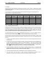
For this example, the following table shows the proper configuration settings for Encoder Multiplier and
Encoder Divisor for 16 typical Step Resolutions:
Step
Resolution
200
400
1,000
2,000
5,000
10,000
12,800
18,000
6.3.2
Table 6.1 – Example Encoder Multiplier and Divisor Values
Encoder
Encoder
Step
Encoder
Multiplier
DIvisor
Resolution
Multiplier
1
5
20,000
20
2
5
21,600
108
1
1
25,000
25
2
1
25,400
127
5
1
25,600
128
10
1
36,000
36
64
5
50,000
50
18
1
50,800
254
Encoder
Divisor
1
5
1
5
5
1
1
5
Configuring Encoder Tolerance
If the Encoder Tolerance is set to 0, position validation is disabled. Otherwise, if Encoder Tolerance is set to
a number from 1 to 255, Encoder Feedback is used to validate current position. As such, the STP100
continuously compares the Encoder Position value (%AI3 and %AI4) to the Motor Position value (%AI1 and
%AI2). If the difference exceeds the configured Encoder Tolerance value, a position validation error has been
detected, and the STP100 turns the Current Position Valid Status bit (%I9) OFF.
An invalid position during a move does not automatically stop the move. It is up to the ladder program to
monitor the Current Position Valid bit, and then to issue the Immediate Stop command, if desired.
In an ideal motion control loop, Encoder Position and Motor Position always match exactly. However, when
Encoder Position and Motor Position become skewed, it means that one or more of the following errors has
occurred:
1. A change in motor direction produced a backlash caused by the mechanical linkage between the motor
and the encoder.
2. A resolution error has occurred, because the encoder is less precise than the motor micro-stepping rate.
In other words, Step Resolution is greater then Encoder Resolution. This is quite common for Step
Resolutions greater than 2000 steps per revolution. For most motors, Step Resolutions greater than
2000 do not afford better positioning accuracy, but merely offer smoother operation. In these cases, it
does not make sense to spend the extra money for an extremely fine-pitched encoder.
3. The Step Resolution exceeds the motor’s ability to accurately position its rotor. For example, most
stepper motors have an accuracy of 1 part in 2000, which means a Step Resolution greater than 2000
has little affect on accuracy, but only contributes to smoother operation.
4. The motor missed some step pulses or stalledbecause of low or mid-frequency resonance.
5. The motor missed some step pulses or stalled, because the programmed Acceleration Time or
Deceleration Time was too low to properly overcome the mechanical inertia of the system.
PAGE 42
SUP0270-02
10 FEB 2000
CH. 6: USING ENCODERS
6. Some external force changed the position of the motor. For example, something caught in the machinery
does not let the motor move the load as requested.
6.3.3
Configuring Motor Stall Detection
If desired, Motor Stall Detection can be enabled by checking the Enable Stall Detection checkbox on the
STP100’s configuration screen. When this option is enabled, the STP100 monitors Encoder Feedback pulse
velocity to determine whether or not the motor has stalled.
In particular, if the measured move velocity falls to less than 10% of the theoretical move velocity, then a
Motor Stalled error has been detected. When this happens, the STP100 stops sending step pulsesand turns
the Motor Stalled Error Status bit (%I5) ON.
CH. 7: WIRING
10 FEB 2000
PAGE 43
SUP0270-02
CHAPTER 7: WIRING
7.1
General
Chapter Seven provides example wiring diagrams for interconnection between the STP100 and external
equipment, such as stepper motor translator drives, encoders and switches.
7.2
Translator Drives
The STP100 does not provide the necessary signals to drive a stepper motor directly. A Translator Drive is
required. The Translator Drive can be in a separate enclosure, or it can be contained within the motor
housing itself. The Translator Drive accepts Step and Direction signals from the STP100 and generates the
signals necessary to drive the motor.
The STP100 is compatible with three common Translator Drive electrical interfaces: differential (RS-485),
5VDC positive going, and 5VDC negative going. Note that 5VDC signals, can be also be referred to as TTLCompatible signals. Figures 7.1, 7.2 and 7.3 show the proper wiring for the 3 different interface types. Note
that the Step and Direction signals are not isolated from common ground.
HE800STP100
Step+ Pin 17
+STEP
Step-- Pin 18
-- STEP
Direction+ Pin 15
Direction-- Pin 16
+DIR
Translator
-DIR
Figure 7.1 - Interfacing to a Translator Drive Using Differential Signals
HE800STP100
GND Pin 8 or 19
Step+ Pin 17
Direction+ Pin 15
GND
+STEP
Translator
+DIR
Figure 7.2 - Interfacing to a Translator Drive Using Positive 5VDC Signals
PAGE 44
SUP0270-02
10 FEB 2000
CH. 7: WIRING
HE800STP100
GND Pin 8 or 19
Step-- Pin 18
GND
--STEP
Translator
--DIR
Direction-- Pin 16
Figure 7.3 - Interfacing to a Translator Drive Using Negative 5VDC Signals
7.3
Encoders
Encoders are optional devices. The STP100 is compatible with encoders which produce either differential
signals or 5 VDC positive-going (TTL-compatible) signals.
Note that the Encoder signals are not isolated from common ground.
HE800STP100
+ENCA
-ENCA
Encoder
+ENCB
-ENCB
Marker
(optional)
+MARK
-MARK
Pin 11
Pin 12
Pin 13
Pin 14
Pin 9
Pin 10
Figure 7.4 - Interfacing to an Encoder with Different Outputs
HE800STP100
Encoder
+ENCA
Pin 11
+ENCB
Pin 13
GND
Marker
(optional)
+MARK
GND
Pin 8 or 19
Pin 9
Pin 8 or 19
Figure 7.5 - Interface to an Encoder with Positive 5VDC Signals
CH. 7: WIRING
7.4
10 FEB 2000
PAGE 45
SUP0270-02
Isolated Switch Inputs
The STP100 accepts several different isolated switch inputs:
Pin
1
2
3
4
5
6
7
Signal
Isolated Common
ESTOP+
LOLIMHILIMHOMEINDEXIsolated Common
Table 7.1 - User-Supplied Switch Inputs
Marking
Description
IC
Isolated Common
ES
Emergency Stop, Active High (Open), 24VDC pull-up
LO
Low Limit, Active Low (Closed) 24 VDC pull-up
HI
High Limit, Active Low (Closed) 24 VDC pull-up
HO
Home, Active Low (Closed) 24 VDC pull-up
IN
Index, Active Low (Closed) 24 VDC pull-up
IC
Isolated Common
All switch inputs are optically isolated to 500 VDC. This is accomplished by the following circuit inside the
STP100. (Circuitry inside the dotted line is physically located inside the SmartStack module.) Home, Low
Limit, High Limit and Index can accept either mechanical switch closures or NPN-type proximity switches.
+24VDC
3.9K
24K
Normally Open (N/O)
switch
Isolated
Ground
Figure 7.6 - Isolated Input Schematic
Home, Low Limit, High Limit, and Index are active low signals. A Normally Open (N/O) switch is required
to switch these lines to ground when the switch is activated.
Emergency Stop is an active high signal. A Normally Closed (N/C) switch is required to hold this line to a
LOW (grounded) condition for normal operation of the system.
PAGE 46
SUP0270-02
10 FEB 2000
NOTES
CH. 7: WIRING
INDEX
10 FEB 2000
PAGE 47
SUPO270-02
INDEX
Acceleration Time ............................................. 27
Addressing........................................................ 17
Base Velocity .................................................... 27
Command Bit Output Register........................... 29
Command Word Output Registers..................... 26
Commands ....................................................... 31
Available Commands..................................... 31
Clear Errors................................................... 31
Decelerate and Stop...................................... 37
Find Origin Up / Find Origin Down ................. 32
Immediate Stop ............................................. 38
Jog Up and Jog Down ................................... 33
Move Indexed................................................ 35
Move Relative and Move Absolute................. 34
Repeat Move................................................. 36
Resume Move ............................................... 36
Set Current Position ...................................... 37
Configuration .................................................... 19
Using Cscape ................................................ 19
Deceleration Time............................................. 28
Destination Position .......................................... 26
Differential Inputs .............................................. 11
Differential Outputs ........................................... 12
Encoder Position............................................... 25
Encoders .......................................................... 39
Adding........................................................... 39
Configuration................................................. 40
Encoder Tolerance, Configuring .................... 41
Motor Stall Detection, Configuring ..................42
Multiplier and Divisor Value Examples............41
Types of Encoders .........................................39
Error and Status Input Bit Register.....................24
External Wiring..................................................16
Features..............................................................9
I/O Pin-Out .......................................................16
I/O Register Assignments ..................................21
Indexed Deceleration Time................................28
Indexed Window Close Position.........................28
Indexed Window Open Position .........................28
Indicators ..........................................................12
Installation.........................................................15
Isolated Inputs...................................................11
Motion Profiles ..................................................12
Motor Position ...................................................25
Quadrature Encoder ..........................................39
Register Details.................................................24
Register Summary...........................................23
Running Velocity ...............................................27
Signal Descriptions............................................11
Specifications ....................................................10
Up / Down Encoder ...........................................40
Velocity Divisor..................................................26
Velocity Multipliers (Examples) ......................26
Wiring................................................................43
Isolated Switch Inputs ....................................45
Translator Drives............................................43
PAGE 48
SUP0270-02
10 FEB 2000
INDEX