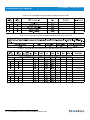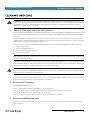
1
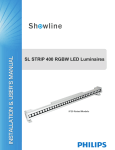
Sh wline
SL eSTROBE 130 LED Luminaire
www.Philips.com/Showline
The material in this manual is for information purposes only and is subject to change without notice. Showline
assumes no responsibility for any errors or omissions which may appear in this manual. For comments and
suggestions regarding corrections and/or updates to this manual, please visit the Showline website at
www.philips.com/showline or contact your nearest Showline office.
Note: Information contained in this document may not be duplicated in full or in part by any person without prior written
approval of Showline. Its sole purpose is to provide the user with conceptual information on the equipment mentioned. The use of
this document for all other purposes is specifically prohibited.
SL eSTROBE 130 User’s Manual
24-004-3590-00 Rev1.0
SL eSTROBE 130 LED Luminaire installation & User’s Manual
2013 Philips Group. All rights reserved.
SL eSTROBE 130 LED Luminaire
Installation & User’s Manual
Warnings and Notices
When using electrical equipment, basic safety precautions should always be followed including the following:
READ AND FOLLOW ALL SAFETY INSTRUCTIONS.
Do not use outdoors.
Do not mount near gas or electric heaters.
Equipment should be mounted in locations and at heights where it will not readily be subject
to tampering by unauthorized personnel.
The use of accessory equipment not recommended by the manufacturer may cause an unsafe
condition.
Do not use this equipment for other than intended use.
Refer service to qualified personnel.
WARNING: You must have access to a mains circuit breaker or other power disconnect device
before installing any wiring. BE sure that power is disconnected by removing fuses or turning the
mains circuit breaker off before installation. Installing the device with power on may expose you
to dangerous voltages and damage the device. A qualified electrician must perform this installation.
WARNING: Refer to National Electrical Code and local codes for cable specifications.
Failure to use proper cable can result in damage to equipment or danger to personnel.
WARNING: This equipment is intended for installation in accordance with the Nation Electric
Code and local regulations. It is also intended for installation in indoor applications only. Before
any electrical work is performed, disconnect power at the circuit breaker or remove the fuse to
avoid shock or damage to the control. It is recommended that a qualified electrician perform this
installation.
Additional Resources for DMX512
For more information on installing DMX512 control systems, the following publication is available for purchase
from the United States Institute for Theatre Technology (USITT), "Recommended Practice for DMX512: A Guide
for Users and Installers, 2nd edition" (ISBN: 9780955703522). USITT Contact Information:
USITT
315 South Crouse Avenue, Suite 200
Syracuse, NY 13210-1844
Phone: 1.800.938.7488 or 1.315.463.6463
www.usitt.org
Showline Limited Two-Year Warranty
Showline offers a two-year limited warranty of its luminaires against defects in materials or workmanship from the
date of delivery. A copy of Showline two-year limited warranty containing specific terms and conditions can be
obtained by contacting your local Showline office.
Installation & User’s Manual
SL eSTROBE 130 LED Luminaire
TABLE OF CONTENTS
Showline Offices
IMPORTANT INFORMATION
Warnings and Notices
Additional Resources for DMX512
Showline Limited Two-Year Warranty
TABLE OF CONTENTS
PREFACE
About this Manual
Included Items
Inside Front Cover
1
1
1
3
3
SL eSTROBE 130 LED LUMINAIRE OVERVIEW
SL eSTROBE 130 LED Luminaire Components
Common Luminaire Components
LCD Display / Menu System
INSTALLATION AND SET UP
Power Requirements
Connecting Power
Connecting to the DMX512 Network
Mounting Luminaire
Floor Mounting
Truss Mounting
OPERATION AND PROGRAMMING
LCD Display and Menu System
SL eSTROBE 130 LED Luminaire
LCD Display and Menu System Operation
SL eSTROBE 130 LED Luminaire Menu Tree
Dimming Curve Selection
Master / Slave Operational Mode
4
4
5
6
6
6
7
7
7
8
8
8
10
11
12
DMX CONTROL
SL eSTROBE 130 LED Luminaire DMX Mapping
Single Channel Mode
Three Channel Mode
Four Channel Mode
16-Bit Mode
Zone Mapping Mode
Strobe Rate
Strobe During
13
13
14
15
16
17
23
RDM PARAMETER IDs
SL eSTROBE 130 LED Luminaire RDM Parameter IDs
28
CLEANING AND CARE
Special Cleaning and Care Instructions
Front Lens Cleaning
Service and Maintenance
Accessories
31
31
31
32
13
TECHNICAL SPECIFICATIONS
Operational Specifications
Luminaire Dimensions
2
Table of contents
33
34
SL eSTROBE 130 LED Luminaire
Installation & User’s Manual
PREFACE
1.
About this Manual
The document provides installation and operation instructions for the following products:
SL eSTROBE 130 LED Luminaire
Please read all instructions before installing or using this product. Retain this manual for future reference.
Additional product information and descriptions may be found on the product specification sheet.
Note: The SL eSTROBE 130 LED Luminaire is universal voltage 100 to 240 VAC (auto-ranging).
2.
Included Items
Each SL eSTROBE 130 LED Luminaire includes the following items:
SL eSTROBE 130 LED Luminaire
AC Power Input Cable
Installation and User’s Manual (this document)
About this Manual
3
Installation & User’s Manual
SL eSTROBE 130 LED Luminaire
SL eSTROBE 130 LED Luminaire Overview
1.
SL eSTROBE 130 LED Luminaire Components
Common Luminaire Components
Front of Unit
Rear of Unit
DMX512-A /
RDM Input
DMX512-A /
RDM THRU
Yoke Assembly
High Intensity LED Array
LCD Display /
Menu System
AC Power Input
Accessory Holder Clip
Accessory Holder
Yoke (Tilt) Position
Locking Handle
Truss Hook / Clamp
Attachment Point
Figure 1: SL eSTROBE 130 LED Luminaire Components
4
SL eSTROBE 130 LED Luminaire Overview
Installation & User’s Manual
SL eSTROBE 130 LED Luminaire
LCD Display / Menu System
LCD Display
ENTER(OK) Button
EXIT Button
LEFT Arrow Button
RIGHT Arrow Button
Figure 2: LCD Display & Menu System
Note: For Menu operation and programming details, refer to the "LCD Display and Menu System” on page 8.
LCD Display/Menu System
5
Installation & User’s Manual
SL eSTROBE 130 LED Luminaire
INSTALLATION AND SET UP
1.
Power Requirements
The SL eSTROBE 130 LED Luminaire operates on AC input voltages from 100 to 240 VAC.
WARNING! This luminaire does not contain an ON/OFF switch. Always disconnect power input cable to completely
remove power from the luminaire when not in use.
AC Power Operation
When connected to an AC source, the luminaire operates on 100 to 240 volts AC (+/- 10%, auto-ranging). The
luminaire contains an auto-ranging power supply. Each luminaire can draw up to 130 Watts.
Table 1: SL eSTROBE 130Voltage (VAC) vs. Current
2.
Voltage (AC)
Total Current (A)
Voltage (AC)
Total Current (A)
100
110
120
130
140
150
160
170
1.30
1.18
1.08
1.00
0.92
0.86
0.81
0.76
180
190
200
210
220
230
240
0.72
0.68
0.65
0.62
0.59
0.56
0.54
Connecting Power
Direct connection to a AC power source using an AC input cable.
3.
Connecting to the DMX 512 Network
Basic DMX512 installation consists of connecting multiple SL eSTROBE 130 LED Luminaires together (up to 32
luminaires) in "daisy-chain" fashion. A cable runs from the control console (or DMX512 control source) to the DMX
connector on the first SL eSTROBE 130 LED Luminaire. Another cable runs from the other DMX connector on
the first Luminaire to a DMX connector on the next SL eSTROBE 130 LED Luminaire (or DMX512 device to be controlled).
Rear of Unit
DMX512-A / RDM
Input Connector
DMX512-A / RDM
THRU Connector
Luminaire
Figure 3: SL eSTROBE 130 LED Luminaire DMX512 Input / THRU Connections
6
Installation and Set up
Installation & User’s Manual
SL eSTROBE 130 LED Luminaire
Note: For more information on DMX512 networking and systems, refer to "Additional Resources for DMX512" on
page 1. For SL eSTROBE 130 LED Luminaire DMX Mapping, refer to "DMX CONTROL" on page 13.
DMX512 Connections
DMX512
DMX512 Signal
(from console or
control device)
Common (Drain)
1
DMX512 -
2
DMX512 +
3
DMX512 (out from first
DMX512 (out to the next luminaire or
to second luminaire)
DMX512 controlled device)
XLR Pin
Note: Remaining pins on each connector are not used.
Figure 4: SL eSTROBE 130 LED Luminaire - DMX512 Connections
4.
Mounting Luminaire
Floor Mounting
The SL eSTROBE 130 LED Luminaire is designed to sit directly on its yoke assembly in a floor installation application.
When used in this type of application, loosen the locking handle securing the inner portion of the yoke assembly and
separate out (as shown in Figure 5). Be sure to leave enough space around the luminaire to allow proper,
uninterrupted airflow for cooling.
Yoke Assembly
Inner Portion (Stand)
of Yoke Assembly
Figure 5: Floor Mounting
Truss / Hanging Applications
The SL eSTROBE 130 LED Luminaire is provided with the ability to hang via truss hooks, clamps, etc. (soldseparately).
Simply attach hook, clamp, etc. to the SL eSTROBE 130 LED Luminaire enclosure assembly in the provided M10
holes. It is recommended (and may be required by local and national safety codes) to use and install a safety cable
(sold separately) as illustrated in Figure 6. When hanging the fixture, be sure to leave enough space around the luminaire
to allow proper, uninterrupted airflow for cooling and positioning. Refer to "Luminaire Dimensions" on page 34 for
spacing (dimensional) requirements.
Figure 6: Truss Mounting
Mounting Luminaire
7
Installation & User’s Manual
SL eSTROBE 130 LED Luminaire
OPERATION AND PROGRAMMING
1.
LCD Display and Menu System
SL eSTROBE 130 LED Luminaires
The SL eSTROBE 130 LED Luminaire’s LCD Display and Menu System provides local control for accessing the
following fixture’s settings:
Presets (Standard and User Defined)
Chase
Settings
Status
Note: If there are multiple luminaires in a system, changes would need to be made at each LCD Menu as desired. For
the SL eSTROBE 130 LED Luminaire menu structure, see "SL eSTROBE 130 LED Luminaire Menu Tree" on page 10.
Upon power up, the LCD will display the main screen display menu of SL eSTROBE 130 LED Luminaire.
Press “ ” or “ ” to select then press 'OK' to enter.
LCD Display
ENTER Button
EXIT Button
LEFT Arrow Button
RIGHT Arrow Button
Figure 7: LCD Display and Menu System
2. LCD Display and Menu System Operation
The LCD Display Menu system consists of several categories. Upon power up, the LCD will display the main menu
automatically. When the desired menu item is reached, press the OK button to display the menu options, and to navigate
and configure the menu options as required.
To navigate and access the menu settings/selections:
Step 1. Make sure the luminaire is powered and turned on.
Step 2. Press the desired button to access the menu categories.
Step 3. Use the “ ” and “
” arrow buttons to navigate through the various options and settings.
Step 4. Make changes as desired.
Press the OK button to accept changes.
8
OPERATION AND PROGRAMMING
Installation & User’s Manual
SL eSTROBE 130 LED Luminaire
Preset
To edit and save a preset
Main Menu
1. Preset
Press the OK button to access the Preset menu.
Use the LEFT and RIGHT arrow buttons to scroll through all presets
and select the desired preset number.
Press the OK button to select the desired menu. In RGB
mode, the user can select Intensity, Strobe Rate, Duration,
Effects, Zone1, Zone2, Zone3 and Zone4.
Once at the desired preset, use theLEFT and RIGHT arrow buttons to
adjust parameter value as desired. Once all values are adjusted as
desired, press the OK button.
Press the ESC button to select Save a Preset, the screen will then
display “Save Preset: x”. Use the LEFT and RIGHT arrow
buttons to make a selection, then press the OK button.
Step 5. The preset is now saved. Press the ESC button to exit the current menu.
Step 5.
Chase
Select Chase and press the OK button to access.
Use the LEFT and RIGHT arrow buttons to scroll through all menus.
. Chase
1. Chase Select
Select the Built-in Chase X(1-10) option or the User Chase(1-8) option ,
then press the OK button to select the desired menu.
Once at desired menu, use the LEFT and RIGHT arrow buttons to
adjust the parameter value as desired. Once all values are adjusted as
desired, press the OK button.
Step 5. The chase is now saved. Press the ESC button to exit the current menu.
Settings
Press the OK button to access Settings.
Use the LEFT and RIGHT arrow buttons to scroll through all menus.
Press the OK button to select the desired menu
among General, Factory Default, DMX and Display.
.Settings
1. General
Once at desired menu, use LEFT and RIGHT arrow buttons to
adjust the related fixture information. Once all values are adjusted
as desired, press CHECK MARK (OK)button.
Step 5. Adjustment is now saved. Press ESC button to exit current menu.
Status
To check the fixture operational status:
Press CHECK MARK(OK)button to access Status.
.Status
1. LED Level
Use the LEFT and RIGHT arrow buttons to scroll through all menus.
Press the OK button to select the desired menu
from LED Level, Temperature, and Other Info.
Once at the desired menu, use the LEFT and RIGHT arrow buttons to
check the related fixture information.
Note: For more information about Preset, Color Filter, Chase, Strobe/Timing, Settings and Status, please
refer to the “SL eSTROBE 130 LED Luminaire Menu Tree” on page 11.
LCD Display and Menu System Operation
9
Installation & User’s Manual
3.
SL eSTROBE 130 LED Luminaire
SL eSTROBE 130 LED Luminaire Menu Tree
Figure 8: SL eSTROBE 130 LED Luminaire Menu Tree
10
SL eSTROBE 130 LED Luminaire Menu Tree
Installation & User’s Manual
SL eSTROBE 130 LED Luminaire
4. Dimming Curve Selection
Through the menu, you are able to select one of four dimming curves:
Linear Curve
PL_Curve
S_Curve
Square Curve
PL_Curve
Lumen Output
Lumen Output
Linear Curve
DMX Value
DMX Value
*PL Curve follows the dimming curve of Philips Selecon PL
series LED luminaires.
S_Curve
Lumen Output
Lumen Output
Square Curve
DMX Value
DMX Value
Figure 9: SL eSTROBE 130 LED Luminaire Dimmer Curves
Dimming Curve Selection
11
Installation & User’s Manual
SL eSTROBE 130 LED Luminaire
5
The Master / Slave Operational Mode allows one SL eSTROBE 130 LED Luminaire to act as the “Master” luminaire
and all other connected luminaire s are controlled by this master luminaire. When a luminaire is set to
“Slave” mode, it will only luminaire and follow any commands send from a “Master” luminaire . Only one
“Master” luminaire is allowed in this type of operation.
To setup a master / slave network:
Step 1. Set the first luminaire in the DMX512 chain to Master Mode through the luminaire ’s menu system.
Step 2. Set all other connected luminaire s to Slave Mode.
Step 3. The master luminaire can be controlled via DMX512, RDM or through standalone operation(a self
-contained network utilizing on-board effects). The salve luminaire s will mimic the master luminaire ’s
operation in all cases.
Note: For more information on DMX512 networking and systems, refer to “Additional Resources for DMX512”
on page 1. For SL eSTROBE 130 LED Luminaire DMX Mapping, refer to “DMX CONTROL” on page 13.
Master Luminaire
Slave Luminaire
Slave Luminaire
Figure 10: SL eSTROBE 130 LED Luminaire - Master / Slave Configuration
12
Master / Slave Operational Mode
Installation & User’s Manual
SL eSTROBE 130 LED Luminaire
This section contains information for operating the luminaire using DMX control in Single Channel, Three
Channel, Four Channel, 16-Bit Control or Zone Mapping modes. For Menu options and detailed information,
see the “LCD Display and Menu System” on Page 8.
Note: These tables assume a DMX start address of 1. When a different starting address is used, this address
becomes channel 1 function and other functions follow in sequence.
1.
SL eSTROBE 130 LED Luminaire DMX Mapping
Single Channel Mode
Table 2 provides DMX channel mapping of all DMX512 control values when the SL eSTROBE 130
LED Luminaire is in Single Channel mode (as set by the luminaire’s menu system).
Table 2: SL eSTROBE 130 LED Luminaire DMX Channel Mapping (Single Channel Mode)
DMX
Channel
1
Parameter
Range DMX
Strobe Rate
0 - 255
Range%
0 - 100%
Default- recommended
console default values
Description
0
Please refer to the Strobe Rate detail.
Three Channel Mode
Table 3 provides DMX channel mapping of all DMX512 control values when the SL eSTROBE 130
LED Luminaire is in Three Channel mode (as set by the luminaire’s menu system).
Table 3: SL eSTROBE 130 LED Luminaire DMX Channel Mapping (Three Channel Mode)
DMX
Channel
Parameter
Range DMX
Range%
Default- recommended
console default values
Description
1
Intensity
0 - 255
0 - 100%
0
8 bit control for Intensity of LED settings
2
Strobe Duration
0 - 255
0 - 100%
0
Strobe’s duration, Range is 0-255
White light mode ( when strobe rate is also at 255)
Please refer to the Strobe Duration Detail
3
Strobe Rate
0 - 255
0 - 100%
0
Strobe rate slow to fast.
White light mode ( when strobe duration is also at 255)
Please refer to the Strobe Rate Detail.
DMX Control
13
Installation & User’s Manual
SL eSTROBE 130 LED Luminaire
Four Channel Mode
Table 4 provides DMX channel mapping of all DMX512 control values when the SL eSTROBE 130
LED Luminaire is in Four Channel mode (as set by the luminaire’s menu system).
Table 4: SL eSTROBE 130 LED Luminaire DMX Channel Mapping (Four Channel Mode)
DMX
Channel
Parameter
Range DMX
Range%
Default- recommended
console default values
Description
1
Intensity
0 - 255
0 - 100%
0
8 bit control for Intensity of LED settings
2
Strobe Duration
0 - 255
0 - 100%
0
Strobe’s duration, Range is 0-255
White light mode ( when strobe rate is also at 255)
Please refer to the Strobe Duration Detail
3
Strobe Rate
0 - 255
0 - 100%
0
Strobe rate slow to fast.
White light mode ( when strobe duration is also at 255)
Please refer to the Strobe Rate Detail.
4
Effects
0 - 255
0 - 100%
0
Controls strobe operations as follows:
No Effect
Ramp Up
Ramp Down
Ramp Up/Down
Random
Ring 1
Ring 2
Ring 3
Ring 4
Checker pattern A
Checker pattern B
Random zones
Circle zone chase clockwise
Circle zone chase counter-clockwise
14
DMX Control
= DMX 0-5
= DMX 6-42
= DMX 43-85
= DMX 86-128
= DMX 129-171
= DMX 172-173
= DMX 174-175
= DMX 176-179
= DMX 180-182
= DMX 183-184
= DMX 185-186
= DMX 187-214
= DMX 215-235
= DMX 236-255
Installation & User’s Manual
SL eSTROBE 130 LED Luminaire
16-Bit Mode
Table 5 provides DMX channel mapping of all DMX512 control values when the SL eSTROBE 130
LED Luminaire is in 16-Bit mode (as set by the luminaire’s menu system).
Table 5: SL eSTROBE 130 LED Luminaire DMX Channel Mapping (16-Bit Mode)
DMX
Channel
Parameter
1
Intensity High
2
Intensity Low
3
Effects
Range DMX
Range%
Default- recommended
console default values
0 - 65535
0 - 100%
0
0 - 255
0 - 100%
DMX 0
Description
16 bit control for Intensity of LED settings
Controls strobe operations as follows:
No Effect
Ramp Up
Ramp Down
Ramp Up/Down
Random
Ring 1
Ring 2
Ring 3
Ring 4
Checker pattern A
Checker pattern B
Random zones
Circle zone chase clockwise
Circle zone chase counter-clockwise
= DMX 0-5
= DMX 6-42
= DMX 43-85
= DMX 86-128
= DMX 129-171
= DMX 172-173
= DMX 174-175
= DMX 176-179
= DMX 180-182
= DMX 183-184
= DMX 185-186
= DMX 187-214
= DMX 215-235
= DMX 236-255
4
Control Channel
0 - 255
0 - 100%
0
Please refer to the Control Channel detail.
5
Strobe Duration
0 - 255
0 - 100%
0
Strobe’s duration, Range is 0-255
White light mode ( when strobe rate is also at 255)
Please refer to the Strobe Duration Detail
6
Strobe Rate
0 - 255
0 - 100%
0
Strobe rate slow to fast.
White light mode ( when strobe duration is also at 255)
Please refer to the Strobe Rate Detail.
16-Bit Mode
15
Installation & User’s Manual
SL eSTROBE 130 LED Luminaire
Zone Mapping Mode
Table 6 provides DMX channel mapping of all DMX512 control values when the SL eSTROBE 130
LED Luminaire is in Zone Mapping mode (as set by the luminaire’s menu system).
Table 6: SL eSTROBE 130 LED Luminaire DMX Channel Mapping (Zone Mapping Mode)
16
DMX
Channel
Parameter
1
2
Range DMX
Range%
Default
Master Intensity - High
Master Intensity - Low
0 - 65535
0 - 100%
0
16 bit control for Intensity of LED settings.
3
Effects
0 - 255
0 - 100%
0
Effects.( Refer to the Effects detail)
4
Control Channel
0 - 255
0 - 100%
0
Control Channel(Refer to the Control Channel detail)
5
Zone 1 Intensity
0 - 255
0 - 100%
0
8-bit control for zone Intensity.
6
Zone 1 Strobe Duration
0 - 255
0 - 100%
0
Strobe’s duration(Refer to the Strobe Duration Detail.)
7
Zone 1 Strobe Rate
0 - 255
0 - 100%
0
Strobe’s rate slow to fast.(Refer to the Strobe Rate detail)
8
Zone 2 Intensity
0 - 255
0 - 100%
0
8-bit control for zone Intensity.
9
Zone 2 Strobe Duration
0 - 255
0 - 100%
0
Strobe’s duration(Refer to the Strobe Duration Detail.)
10
Zone 2 Strobe Rate
0 - 255
0 - 100%
0
Strobe’s rate slow to fast.(Refer to the Strobe Rate detail)
11
Zone 3 Intensity
0 - 255
0 - 100%
0
8-bit control for zone Intensity.
12
Zone 3 Strobe Duration
0 - 255
0 - 100%
0
Strobe’s duration(Refer to the Strobe Duration Detail.)
13
Zone 3 Strobe Rate
0 - 255
0 - 100%
0
Strobe’s rate slow to fast.(Refer to the Strobe Rate detail)
14
Zone 4 Intensity
0 - 255
0 - 100%
0
8-bit control for zone Intensity.
15
Zone 4 Strobe Duration
0 - 255
0 - 100%
0
Strobe’s duration(Refer to the Strobe Duration Detail.)
16
Zone 4 Strobe Rate
0 - 255
0 - 100%
0
Strobe’s rate slow to fast.(Refer to the Strobe Rate detail)
Zone Mapping
Description
Installation & User’s Manual
SL eSTROBE 130 LED Luminaire
Strobe Rate
Table 7 provides Strobe Rate values of SL eSTROBE 130 LED Luminaire.
Table 7: SL eSTROBE 130 LED Luminaire Strobe Rate
DMX Value
Percent(%)
0
0
1
2
3
1
4
5
Frequency(Hz)
DMX 0-5 – No Flash
(single flash with
value>5 on intensity
one time
2
6
0.500
7
0.500
8
3
9
10
0.504
4
0.512
12
5
6
17
0.521
7
19
20
8
0.530
0.530
0.535
22
9
0.535
0.540
24
25
0.526
0.526
21
23
0.517
0.521
16
18
0.512
0.517
14
15
0.508
0.508
11
13
0.504
10
0.540
26
0.544
27
0.544
28
11
29
0.549
0.554
30
31
12
0.554
0.559
32
33
0.549
13
0.559
34
0.559
35
0.565
36
14
38
15
0.575
40
16
44
0.581
0.581
42
43
0.570
0.575
39
41
0.565
0.570
37
17
0.586
0.586
Strobe Rate
17
Installation & User’s Manual
SL eSTROBE 130 LED Luminaire
Table 7: SL eSTROBE 130 LED Luminaire Strobe Rate
DMX Value
Percent(%)
46
18
19
0.598
0.604
49
0.604
50
51
0.592
0.598
47
48
Frequency(Hz)
0.592
45
20
0.610
52
0.610
53
0.616
54
21
56
22
0.629
58
23
24
62
0.642
25
26
0.663
68
27
28
72
0.678
29
30
0.701
78
31
0.709
81
32
33
0.735
34
18 SL eSTROBE 130 LED Luminaire Strobe Rate
0.735
0.735
88
89
0.726
0.726
85
86
87
0.717
0.717
83
84
0.701
0.709
80
82
0.693
0.693
77
79
0.685
0.685
75
76
0.670
0.678
73
74
0.663
0.670
70
71
0.656
0.656
67
69
0.649
0.649
65
66
0.635
0.642
63
64
0.635
0.635
60
61
0.622
0.629
57
59
0.616
0.622
55
35
0.744
Installation & User’s Manual
SL eSTROBE 130 LED Luminaire
Table 7: SL eSTROBE 130 LED Luminaire Strobe Rate
DMX Value
Percent(%)
Frequency(Hz)
90
0.744
91
0.753
92
36
0.762
93
94
37
0.772
96
38
39
0.802
101
40
0.813
41
0.824
0.824
106
107
0.802
0.813
103
104
105
0.792
0.792
100
102
0.782
0.782
98
99
0.762
0.772
95
97
0.753
42
0.835
108
0.835
109
0.847
110
43
0.859
111
112
0.847
44
0.859
113
0.871
114
0.663
115
45
117
46
119
0.685
47
48
0.701
49
127
0.717
50
129
130
51
0.726
0.735
131
134
0.717
0.726
0.735
132
133
0.709
0.709
126
128
0.693
0.701
123
124
125
0.685
0.693
121
122
0.678
0.678
118
120
0.670
0.670
116
52
0.735
0.744
Strobe Rate
19
Installation & User’s Manual
SL eSTROBE 130 LED Luminaire
Table 7: SL eSTROBE 130 LED Luminaire Strobe Rate
DMX Value
Percent(%)
Frequency(Hz)
135
54
1.016
1.033
136
137
1.033
138
1.051
54
1.051
139
140
55
1.070
141
1.070
142
1.089
143
56
144
145
1.089
57
1.129
147
58
1.129
59
1.150
1.150
149
150
1.109
1.109
146
148
1.089
151
1.173
152
1.173
153
60
154
1.220
155
156
61
1.220
1.244
157
158
1.196
1.196
62
1.244
159
1.270
160
1.270
161
63
162
163
1.297
64
164
1.355
65
1.355
1.386
167
168
1.326
1.326
165
166
1.297
66
1.386
169
1.418
170
1.418
171
67
172
173
1.452
0.717
68
0.717
174
0.726
175
0.726
176
69
0.735
178
179
20 SL eSTROBE 130 LED Luminaire Strobe Rate
0.735
0.735
177
70
0.744
Installation & User’s Manual
SL eSTROBE 130 LED Luminaire
Table 7: SL eSTROBE 130 LED Luminaire Strobe Rate
DMX Value
Percent(%)
181
71
1.648
183
72
1.694
1.694
185
186
1.605
1.648
182
184
Frequency(Hz)
1.605
180
73
1.742
187
1.742
188
1.793
189
74
191
75
1.905
193
76
77
197
2.103
78
79
2.258
203
80
2.258
2.345
205
206
2.178
2.178
202
204
2.103
2.103
200
201
2.033
2.033
198
199
1.967
1.967
195
196
1.848
1.905
192
194
1.793
1.848
190
81
2.345
207
2.439
208
2.439
209
82
2.651
211
212
83
2.651
2.772
213
214
2.541
2.541
210
84
2.772
215
2.904
216
2.904
217
85
3.049
86
3.209
3.049
218
219
3.209
220
3.388
221
222
87
3.388
88
3.587
3.587
223
224
Strobe Rate
21
Installation & User’s Manual
SL eSTROBE 130 LED Luminaire
Table 7: SL eSTROBE 130 LED Luminaire Strobe Rate
DMX Value
Percent(%)
Frequency(Hz)
225
3.811
226
3.811
227
89
4.065
228
4.065
229
230
90
4.355
91
4.690
4.355
231
232
4.065
233
4.690
234
5.081
235
92
237
93
6.098
239
94
6.775
95
7.622
6.775
241
242
7.622
243
244
245
8.711
96
97
12.195
249
98
15.244
15.244
251
252
10.163
12.195
248
250
8.711
10.163
246
247
5.543
6.098
238
240
5.081
5.543
236
99
20.325
253
20.325
254
30.488
255
22 SL eSTROBE 130 LED Luminaire Strobe Rate
100
30.488
SL eSTROBE 130 LED Luminaire
Installation & User’s Manual
Strobe Duration
Table 8 provides Strobe Duration values of SL eSTROBE 130 LED Luminaire.
Table 8: SL eSTROBE 130 LED Luminaire Strobe Duration
Strobe Duration
23
Installation & User’s Manual
SL eSTROBE 130 LED Luminaire
Table 8: SL eSTROBE 130 LED Luminaire Strobe Duration
24 SL eSTROBE 130 LED Luminaire Strobe Duration
SL eSTROBE 130 LED Luminaire
Installation & User’s Manual
Table 8: SL eSTROBE 130 LED Luminaire Strobe Duration
Strobe Duration
25
Installation & User’s Manual
SL eSTROBE 130 LED Luminaire
Table 8: SL eSTROBE 130 LED Luminaire Strobe Duration
26 SL eSTROBE 130 LED Luminaire Strobe Duration
SL eSTROBE 130 LED Luminaire
Installation & User’s Manual
Table 8: SL eSTROBE 130 LED Luminaire Strobe Duration
Note: White light mode ( when strobe rate is also at 255)
Strobe Duration
27
Installation & User’s Manual
1.
SL eSTROBE 130 LED Luminaire
SL eSTROBE 130 LED Luminaire RDM Parameter IDs
The following tables outline and describe all the RDM parameters IDs associated with SL eSTROBE 130
LED Luminaires.
Table 9, “SL eSTROBE 130 LED Luminaire RDM Product Parameters IDs”
Table 10, “SL eSTROBE 130 LED Luminaire RDM UID”
Table 11, “SL eSTROBE 130 LED Luminaire RDM Parameters IDs”
Table 12, “SL eSTROBE 130 LED Luminaire RDM Manufacturer Status IDs”, on page 30
Table 13, “SL eSTROBE 130 LED Luminaire RDM Manufacturer Specific PIDs”, on page 30
Table 9: SL eSTROBE 130 LED Luminaire RDM Product Parameters IDs
Model ID
0x2018
Manufacturer
Model Description
Philips Entertainment. Lighting Asia
SL eSTROBE 130
Product Category
0x0509
Table 10: SL eSTROBE 130 LED Luminaire RDM UID
UID
MSB of ESTA
50H
LSB of ESTA
41H
MSB of
Unique Seq
LSB of
Unique Seq
MSB of
Unique Seq
LSB of
Unique Seq
Table 11: SL eSTROBE 130 LED Luminaire RDM Parameters IDs
Get
Allowed
Set
Allowed
RDM Parameter IDs
Value
Comment
Category - Network Managment
DISC_UNIQUE_BRANCH
0x0001
DISC_MUTE
0x0002
DISC_UN_MUTE
0x0003
PROXIED_DEVICES
0x0010
PROXIED_DEVICES_COUNT
0x0011
COMMS_STATUS
0x0015
Category - Status Collection
QUEUED_MESSAGE
0x0020
STATUS_MESSAGES
0x0030
STATUS_ID_DESCRIPTION
0x0031
CLEAR_STATUS_ID
0x0032
SUB_DEVICE_STATUS_REPORT_THRESHOLD
0x0033
Category - RDM Information
SUPPORTED_PARAMETERS
0x0050
Support required only if
supporting Parameters
beyond the minimum required
set.
PARAMETER_DESCRIPTION
0x0051
Support required for
Manuafacturer-Specific PIDs
exposed in SUPPORTED_
PARAMETERS message.
28 SL eSTROBE 130 LED Luminaire RDM Parameter IDs
Impemented
Installation & User’s Manual
SL eSTROBE 130 LED Luminaire
Table 11: SL eSTROBE 130 LED Luminaire RDM Parameters IDs
Get
Allowed
Set
Allowed
RDM Parameter IDs
Value
Comment
Impemented
Category - Product Information
DEVICE_INFO
0x0060
PRODUCT_DETAIL_ID-LIST
0x0070
DEVICE_MODEL_DESCRIPTION
0x0080
MANUFACTURER_LABEL
0x0081
DEVICE_LABEL
0x0082
FACTORY_DEFAULT
0x0090
LANGUAGE_CAPABILITIES
0x00A0
LANGUAGE
0x00B0
SOFTWARE_VERSION_LABLE
0x00C0
BOOT_SOFTWARE_VERSION_ID
0x00C1
BOOT_SOFTWARE_VERSION_LABEL
0x00C2
Category - DMX512 Setup
DMX_PERSONALITY
0x00E0
DMX_PERSONALITY_DESCRIPTION
0x00E1
DMX_START_ADDRESS
0x00F0
SLOT_INFO
0x0120
SLOT_DESCRIPTION
0x0121
DEFAULT_SLOT_VALUE
0x0122
Required if device uses a
DMX Slot
Category - Sensors 0x02xx
SENSOR_DEFINITION
0x0200
SENSOR_VALUE
0x0201
RECORD SENSORS
0x0202
Category - Dimmer Settings 0x03xx - FUTURE USE
Category - Power / Lamp Settings 0x04xx
DEVICE_HOURS
0x0400
LAMP_HOURS
0x0401
LAMP_STRIKES
0x0402
LAMP_STATE
0x0403
LAMP_N_MODE
0x0404
DEVICE_POWER_CYCLES
0x0405
Category - Display Settings 0x05xx
DISPLAY_INVERT
0x0500
DISPLAY_LEVEL
0x0501
Category - Configuration 0x06xx
PAN_INVERT
0x0600
TILT_INVERT
0x0601
PAN_TILT_SWAP
0x0602
REAL_TIME_CLOCK
0x0603
Category - Control 0x10xx
IDENTIFY_DEVICE
0x1000
RESET_DEVICE
0x1001
RDM Parameters IDs
29
Installation & User’s Manual
SL eSTROBE 130 LED Luminaire
Table 11: SL eSTROBE 130 LED Luminaire RDM Parameters IDs
Table 12: SL eSTROBE 130 LED Luminaire RDM Manufacturer Status IDs
Table 13: SL eSTROBE 130 LED Luminaire RDM ManufacturerSpecific PIDs
100
8A00H
1
18
1
Chase
8AB1H
31
0
Preset
8A92H
255
0
Strobe
8A94H
85
0
Duration
8A40H
1
0
8AA1H
3
Dimming Curve
8A0CH
3
DMX FAIL MODE
8AA0H
4
Backlight Off Time
8AA2H
50
Power Up Setup
8A97H
1
8A98H
255
8AB2H
30 SL eSTROBE 130 LED Luminaire RDM Parameters IDs
Link Mode
Fan AUTO / OFF Setup
0
Effect
SL eSTROBE 130 LED Luminaire
Installation & User’s Manual
WARNING!All cleaning should be performed with power completely removed from the luminaire. Never remove
protective covers when the luminaire is powered. Wear appropriate protective eye wear and gloves when cleaning
the luminaire. All service and maintenance, other than described herein, should be performed by a qualified
technician or Authorized Service Center.
1.
Special Cleaning and Care Instuctions
Being a solid-state luminaire, and unlike most luminaire s, the SL eSTROBE 130 LED Luminaire requires very
little routine maintenance by the user. This section covers portions of the luminaire that can be removed for
cleaning.
The SL eSTROBE 130 LED Luminaire requires special care when it comes to cleaning the front lens assembly.
Additional care needs to be taken with the plastic components because they are much easier to scratch or damage
than the glass lenses used in traditional luminaires.
The following is a list of cleaning materials required to care for your SL eSTROBE 130 LED Luminaire:
Lint free lens tissue
Lint or powder free gloves
Reagent frade isopropyl alcohol*
A mild soap solution.
Note: *Reagent grade isopropyl alcohol is good to use on the SL eSTROBE 130 LED Luminaire plastic optics
with anti-relection coatings.
If the lens is still dirty after using isopropyl alcohol, for instance if fingerprints or oil is just redistributed and
not cleaned off the optic, then a mild soap and water solution can be used to gently wash the lens, Repeat the
cleaning with isopropyl alcohol to eliminate streaks and soap residue.
WARNING! Under no circumstances should ammonia-based cleaners, acetone, or other harsh solvents be
used on or near the SL eSTROBE 130 LED Luminaire. These types of cleaners or solvents can permanently
damage the optics or housing of the luminaire.
If you have any questions regarding the use or care of your SL eSTROBE 130 LED Luminaire, please contact
Showline technical support or your local Authorized Dealer.
2. Front Lens Cleaning
To clean the front lens:
Step 1. Turn off the luminaire and allow to cool completely.
Step 2. Apply a small amount of reagent grade isopropyl alcohol to lint-free lens tissue.
Step 3. Wipe all debris, dirt, fingerprints, etc. from lens.
Step 4. Using a second lint-free lens tissue, wipe off any alcohol residue.
3. Service and Maintenance
For all other service and maintenance issues, please contact your local Showline office or an Authorized
Service Centre.
Clean and Care
31
Installation & User’s Manual
SL eSTROBE 130 LED Luminaire
Disassembly (other than as described herein), alterations, unauthorized service, etc. will void
the product warranty. Contact your local Showline office or an Authorized Service Center for technical
support and service.
4.
Accessories
Only Showline approved accessories should be used with your SL eSTROBE 130 LED Luminaire. For a list of
available accessories from Showline, please see “Accessories” on page 3. For questions regarding
accessories, please contact your local Authorized Showline Dealer or Showline office.
32 Accessories
Installation & User’s Manual
SL eSTROBE 130 LED Luminaire
1. Operational Specifications
Source:
Beam Angle:
Light Output:
Color Temperature:
Input Voltage(AC):
Current(AC):
Power Consumption:
Frequency:
Control Protocols:
Ambient Temperature:
Humidity:
Cooling:
Housing:
Weight:
Compliance:
IP Rating:
Cool White Array
120 Degrees
>26,000 lumens
6500K
100V to 240V (+/- 10%, auto-ranging)
1.30 Amps (100V) / 0.54Amps(240V)
130 Watts(max)
50/60Hz
DMX512(1990) / DMX512A(RDM) / On-Board Menu
1 to 40 Degrees C (33 to 104 Degrees F)
35~85 RH%
Forced Air
Die Cast Aluminium with Powder Coating
8.8 lbs(4 kg) - Luminaire only (no accessories)
CE Marked
IP20
Note: Common model specifications shown. For specific model specifications, features, and accessories, refer to the
product specification sheet for more details.
Operational Specifications 33
Installation & User’s Manual
2. Luminaire Dimensions
34 Luminaire Dimensions
SL eSTROBE 130 LED Luminaire
SL eSTROBE 130 LED Luminaire
Installation & User’s Manual
NOTE
Note
35
Dallas
10911 Petal Street
Dalls, TX 75238
Tel: +1 214-647-7880
Fax: +1214-647-8031
Asia
Unit C, 14/F, Roxy Industrial Centre
No. 41-49 Kwai Cheong Road
Kwai Chung, N.T., Hong Kong
Tel: +852 2796 9786
Fax: +852 2798 6545
Auckland
19-21 Kawana Street
Northcote, Auckland 0627
New Zealand
Tel: +64 9 481 0100
Fax: +64 9 481 0101
Europe
Rondweg zuid 85
Winterswijk 7012 JD
The Netherlands
Tel: +31 (0) 543-542516
C 2013 Philips Group